Article

Optimal Design of Water Treatment Contact Tanks

Georgia Institute of Technology, School of Civil and Environmental Engineering, Atlanta, GA 30332, USA
Water 2022, 14(6), 973; https://doi.org/10.3390/w14060973
Submission received: 28 January 2022 / Revised: 15 March 2022 / Accepted: 17 March 2022 / Published: 19 March 2022

Abstract

:
In water treatment facilities, the last step of the treatment process includes disinfectant application to improve the water quality appropriate for a specific end-use purpose. At this step, contact tanks are used to mix water with the disinfectant. Mixing in contact tanks mainly relies on mechanical mixing processes to mix water with the disinfectant to activate the removal process. Thus, mixing efficiency of the contact tank design is critical for the reduction in the amount of disinfectant used to treat a fixed volume of water, to reduce the energy requirements to derive the treated volume of water through the system and to improve other design considerations of the contact tanks. There are numerous design alternatives reported in the literature that do achieve some of these purposes to a certain extent. Among the recent and more successful designs, one can cite the slot-baffle, the perforated-baffle, and the porous-baffle designs. Although these designs provide important improvements to the mixing process, the studies in which these concepts are reported did not provide an optimal design for the baffle geometry used in the design that would include other important considerations beyond the baffle geometry. In this paper, a new optimal design concept is introduced where important design considerations that are not considered in earlier studies are included in the analysis. The results show that new baffle geometries are possible for the optimal design of contact tanks when these innovative design criteria are included in the analysis.

1. Introduction

Continuous disinfection of water effluents is necessary since it is likely that they contain fecal coliform bacteria or other biologic contaminants which may become health hazard when consumed by public [1]. The first continuous use of chlorine treatment for water disinfection was in 1902 in Belgium for the dual objective of aiding coagulation and also making water biologically “safe”. In North America, the first continuous, municipal application of chlorine to water was in 1908 to disinfect water originating from Boonton Reservoir of the Jersey City, N.J. Ever since, the practice of water treatment for public consumption has continued with gradual treatment improvements leading to the traditional water treatment contact tank design, in which water is mixed with disinfectant to enhance the biologic contaminant removal process.
The traditional design of contact tanks is based on the concept of plug flow which assumes that the fluid entering the contact tank is evenly distributed over the entire cross section of the tank chamber and moves in parallel streamlines with a constant and uniform velocity towards the outlet. In this concept, it is assumed that each particle of fluid entering the contact tank chambers remains in it for a time period identified as the “theoretical detention (residence) time”. However, in contact tanks the fluid seldom moves in a piston or plug-flow manner which most of the early design principles were based on. In practice, fluid particles entering the chambers at the same time are found to have unequal residence times, and a significant portion of the fluid leaves the tank with a residence time considerably less than the theoretical residence time. Thus, most existing chlorine or ozone contact tanks suffer from serious the drawbacks of the appearance of dead zones and short circuiting, which reduce the mixing efficiency of the contact tank [2,3]. Since chlorination and ozone treatment practices in water treatment entail a significant amount of capital investment and recurring expenditure of disinfectant use during continuous treatment, it is important that the treatment processes used in disinfection is effective and efficient. For this reason, the improvement of the mechanical mixing efficiency (passive mixing) and the reduction in the energy requirements to drive the flow through system have been the focus of many investigators during the last decade [4,5,6,7,8,9,10,11]. In references [4,5,6,8] one can see the early but modern treatment of the subject of contact tank design using experimental and computational methods. In references [7,9,10] one can see the importance of computational methods and efficiency of mixing performance entering the subject matter of contact tank design. Among these references, probably the reference [11] is the most notable reference since it includes a good summary of the overall contributions made to the subject of design of contact tanks. However, in none of these studies the design concepts used a comprehensive optimization approach as treated in this study.
More recently, vertical or horizontal baffle design configurations were introduced for four-chamber or multi-chamber applications under the category of slot-baffle, perforated-baffle and porous-baffle designs which improved the mixing efficiency of the traditional contact tanks significantly [12,13,14,15,16,17,18,19,20,21]. The references [12,13,14,15,16,17,18,19,20,21] include various conceptual designs in which different versions of the slot-baffle, perforated-baffle and porous baffle geometries were investigated. In references [12,13] the contact tank design was studied from a theoretical perspective using fluid mechanics and vorticity-field concepts in which some of the earlier findings was theoretically reaffirmed. The proposed slot-design concepts were confirmed and supplemented by experimental and computational methods in references [14,15,16]. Among these studies, the most notable references are [17,19] in which the earlier conceptual designs were implemented in a contact tank that was used in the field at Eskisehir municipality water treatment plant in Turkey. However, none of the studies in which these design alternatives were provided investigated the optimal baffle geometry design. These studies provided proof of concept ad hoc baffle geometries in which the conceptual design of the baffle geometry was proposed, and the ensued study quantified the improvements achieved when the proposed baffle configurations are used in the contact tank. However, optimal design considerations have always been an important component of engineering analysis. Thus, the topic of baffle geometry design needs to be studied from an overall optimization analysis concept beyond mere mixing efficiency analysis as reported in earlier studies. In this paper optimal contact tank geometry design will be investigated from the perspective of a new optimization methodology and the use of this methodology in an application to provide a complete optimal perspective for the contact tank design. This approach includes considerations beyond the baffle geometry design that was considered in earlier studies [12,13,14,15,16,17,18,19,20,21].
In this paper, the computational and optimization methods will be used following the simulation-optimization principles to determine the optimal geometry of the vertical slot-baffle design which yielded a completely new slot-baffle geometry when compared with the geometry reported in earlier studies [14,15]. The proposed innovative design concept considers an overall contact tank performance improvement when compared to those reported in the earlier work which only considered mixing performance improvement based on the use of various baffle geometry alternatives [12,13,14,15,16,17,18,19,20,21].

2. Computational and Optimization Models

2.1. Flow Model

Incompressible turbulent flow inside the contact tank is governed by the continuity and momentum equations of CFD analysis:
U i x i = 0
U i t + U j U i x j = 1 ρ p x i + x i ( v U i x j u i ¯ u j ¯ )
where U i is the average flow velocity in the i-direction, u i is fluctuating velocity components in the i-direction, ρ is the fluid density, p is the pressure, t is the time, v is the kinematic viscosity, xi and xj are Cartesian coordinates. Reynolds-averaged Navier-Stokes (RANS) equations are closed using k-ε turbulence closure model for the solution of turbulent flow in the contact tank. Reynolds stresses are approximated by the following Boussinesq hypothesis:
u i ¯ u j ¯ = v t ( U j x i + U i x j ) + 2 3 k δ ij
where δij is the Kronecker delta, k is the turbulence kinetic energy, and v t is the turbulent viscosity, which is defined as,
v t = C μ k ε 2
where Cμ is the model constant and selected as 0.09. Two transport equations are sequentially solved for k and ε using appropriate boundary conditions as given in Section 2.3. Further details of these models can be found in the general fluid mechanics literature and in [12,13].

2.2. Conservative Tracer Model

Efficiency of the contact tank is evaluated by means of tracer simulations for a conservative tracer. The following advection-diffusion equation is solved using the frozen flow concept to propagate the tracer on a developed flow field:
C t + u j C x j = x j ( D t C x j )
where D t is the turbulent diffusivity and C is the tracer concentration. Turbulent diffusivity is calculated as the ratio of the turbulent viscosity ( v t ) to the Schmidt number ( Sc t = 0.7 ) . In the conservative tracer analysis, a fixed concentration of tracer is injected at the inlet and the concentration is observed at the outlet of the tank to obtain residence time distribution (RTD) and cumulative RTD (CRTD) functions, which are used to determine hydraulic and mixing efficiency performance of the contact tank. In this application, the injection time is selected to be less than 5% of the calculated mean residence time (MRT) [22], where:
MRT = Q
where is the contact tank volume and Q is the discharge through the contact tank. The dimensionless tracer concentration and cumulative concentrations are calculated from the following equations:
E ( θ ) = C ( C init ) ( T injection ) / τ
and,
F ( θ ) = 0 E ( θ ) d θ
where Cinit is the injected tracer concentration (Cinit = 1), Tinjection is the injection time, θ = t/τ is the dimensionless time and τ is the MRT.
Open source CFD code OpenFOAM9 [23] is employed for the simulation of turbulent flow and tracer transport through the contact tank. Second order numerical schemes are used for the discretization of convective and diffusive terms in the governing equations to reduce truncation errors [12,13].

2.3. Computational Domain and Boundary Conditions

The contact tank geometry used in this study is shown in Figure 1 [14]. In Figure 1a the dimensions of the baffles and the chambers of the four-chamber contact tank are given in detail for the baffle application without slots. The vertical slot-baffle locations are given as illustration in Figure 1b. The detailed dimensions of the optimal results for the vertical slot-baffle design are given in the results section.
To simulate flow through the contact tank, a three-dimensional computational mesh is generated using the blockMesh utility of OpenFOAM9 [23]. A structured hexagonal mesh system is selected throughout the contact tank idealization, since it is well known that unstructured meshes that are used in these applications produce significant numerical diffusion errors however small the mesh cells are selected in domain idealization. It is well known that smaller mesh cell selections in unstructured mesh applications would amplify the numerical diffusion errors which are important in scalar transport analysis as reported in [24]. Thus, structured mesh configurations are always preferred in scalar transport analysis, as used in this study. The structured hexagonal mesh cells selected in domain idealization are further reduced in size near the contact tank walls, the slots walls, and the top boundary to capture high gradients that may be produced in the flow variables using simpleGrading function of blockMesh. The resultant meshes used in simulation-optimization analysis contain ~6.17 million cells and ~6.36 million nodes to achieve mesh-free convergence. The convergence criteria selected were 1 × 10⁻⁴ for pressure, 1 × 10⁻⁵ for velocity and turbulence quantities, and the steady-state flow field in the flow domain was achieved around (~2586; ~2080) iterations for the given convergence parameters for the baffle configurations used in the analysis. The mesh cell numbers given above slightly varied for various baffle geometries considered in this study in the range 7M to 4M. The use of structured mesh application also facilitated the simulation-optimization computations since the re-meshing that was necessary during the optimization computations were achieved within few seconds on an Intel Core I7/144 Hz computer with 1 TB SSD. The complete cycle of each iteration of a typical application of the simulation-optimization sequence took ~10 h execution time on the desktop computer and this execution time reduces as the iteration process progresses towards convergence. This performance was achieved on a guest Oracle VM/Virtual Box running Ubuntu 64-bit-30 GB VT-x/AMD-V-Nested paging system hosted on the Windows11 platform for the OpenFOAM9 application [23]. A typical mesh used in the analysis can be seen in Figure 2.
The boundary conditions are defined for the flow variables at the inlet, outlet, contact tank baffles and walls, and at the top of the computational domain as given in Table 1 [14].

2.4. Optimization Model

The overall efficiency of the performance of contact tanks needs to be evaluated beyond the perspective of mixing efficiency and baffle geometry design considerations which only considers important but only one aspect of the contact tank performance. The overall performance of the contact tank designed can be evaluated using the four design criteria given below which also includes mixing efficiency:
Criteria Z 1 : Assume that during a typical water treatment application the designed baffle and contact tank geometry provides an acceptable disinfection level at time ( t i ) . Given this period one would adjust the baffle geometry such that the overall disinfection period will be minimized. Thus, among the population of all possible baffle designs i one can identify the best design as the design that would yield,
t d = min t i
In this case the objective function to be minimized will be the expected value of t d computed over the probability distribution of all random baffle geometries that is considered for disinfection.
Z 1 = E ( t d )
where E ( · ) is the expected value and will be approximated by Monte Carlo simulations for the purpose of comparing alternative baffle designs.
Criteria Z 2 : The maximization of the treated water volume during the period ( t d min t i ) for a given baffle geometry can be selected as the second objective. The water volume treated for any scenario can be computed as,
d = Δ t k = 0 N Vol k
Δ t = ( t d t s )
where, Vol k is the amount of treated water volume during each time step of the Δ t time interval, t s is the starting time of the disinfection process and N is the number of time steps in Δ t . According to this criterion, the objective function to be maximized is the expected value computed over the probability distribution of random baffle geometries that are considered.
Z 2 = E ( d )
where E ( · ) again denotes the expected value and will be approximated by Monte Carlo simulation for the purposes of comparing alternative baffle geometry designs.
Criteria Z 3 : This criterion is associated with the reliability of the performance of the baffle design considered. Obviously, some of the baffle designs considered in the contact tank will perform better than others for all Monte Carlo simulations performed. The baffle designs that have higher performance, and thus higher reliability, will be selected in the final design. To measure this criterion the reliability measure r ( X ) is introduced for the t d period. This measure can be defined as,
Z 3 = r ( X ) = 1 N s k = 1 N s d k ( X )
where,
d k = 1 if   the   baffle   design   is   successful , d k = 0 if   the   baffle   design   is   unsuccessful , X population   of   events , baffles   considered , N s Number   of   events   considered . }
In this case, one would like to maximize the reliability measure given in Equation (14).
Criteria Z 4 : The final criterion is associated with the standard disinfection condition to be satisfied within the period t d which would reflect the mixing efficiency of the contact tank. The standard of disinfection criterion can be defined in terms of 3 − log inactivation level for all cases considered which is a standard criteria of water treatment. For this we need to calculate the disinfected concentration level at the outlet of the contact tank for all events considered at the end of the disinfection period t d . This concentration can be calculated as,
C d = Δ t k = 1 N k , i c k , i i = 1 , 2 , 3 , , n
Based on the Monte Carlo simulations considered for all baffle geometries used, criterion Z 4 can be evaluated in terms of the expected value of C d which can be given as,
Z 4 = E ( C d )
These four criteria are all compatible in the following sense. For the optimal design, one would attempt to design a system that would minimize the disinfection period ( Z 1 ) , while maximizing the water volume treated ( Z 2 ) , as the standard criteria of 3 − log disinfection criteria is satisfied for all design considerations in least-squares sense, ( Z 4 ) . Clearly a reliability measure is also needed to rank the degree that the designed baffle configuration system satisfies all three criteria above. Thus, the reliability measure of a proposed design Z 3 should be maximized.
It is emphasized that any optimization analysis that does not consider the four criteria stated above will not yield an overall optimal design considerations for contact tanks since these four criteria reflect the minimum requirements of the optimal contact tank design beyond the baffle geometry design given a conservative chemical treatment process as identified in Equation (5). One can easily recognize that during optimization artificially emphasizing any one of the design criteria given above, such as considering only mixing efficiency over the others will result in different slot-baffle, perforated-baffle or porous-baffle geometries which will not serve the purpose of the overall optimal design concept introduced above. One alternative to minimize the effect of this dilemma is to use a multi-objective optimization approach. However, the multi-objective approach, in one way or another, will eventually be associated with a trade-off methodology in the selection of the final design. Thus, the use of multi-objective optimization technique is not preferred or may not be suitable.
Given these observations, one may start with the premise that there is no single mathematical formulation that would yield all four criteria to reach their true optimal values, which would be otherwise obtained if these criteria were used as a standalone criterion. Thus, in this study our goal is to identify an objective function that would strike a balance between the four objectives without artificial controls for final selection or one that would eventually reflect the preferences of the decision maker in selecting one design among many feasible optimal solutions that may be available. For this purpose, a single-objective formulation approach is selected which combines all four criteria described above in one function [25]. The goal in this approach is to blend the four criteria into one objective function as best as possible and let the optimization process determine the best combined outcome without artificial interference or control. To accomplish this, we start with the following objective function that considers the Criterion Z 4 in least squares sense:
f ( X * ) = min X { i = 1 n t = 1 T [ C i ( t ) C i ( t ) ] 2 }
Subject to the condition,
C i ( t ) = F ( X , t )
X min X X max
where,
C i C d = Δ t k = 1 N k , i c k , i i = 1 , 2 , 3 , , n
and C i ( t ) is the ( 3 log ) inactivation standard for the event considered. In terms of the definitions given earlier, C i ( t ) can be calculated as,
C i C d = k = 1 N t = 0 t d ( t t s in + 1 ) ( k , i c k , i )   i = 1 , 2 , 3 , , n
where, t s in is the beginning time of disinfection period in which the parameter t d (Criterion Z 1 ) and the treated water volume (Criterion Z 2 ) is introduced.
Accordingly, the following objective function can be finally used during optimization which maximizes the reliability function (Criterion Z 3 ), minimizes the disinfection time, maximizes the disinfected volume while the ( 3 log ) disinfection criterion is controlled in least squares sense.
f ( X ) = min X { ( 1 r ( X ) N s ) s = 1 N s { k = 1 N t = 0 t d ( t t s in + 1 ) ( 1 k , i c k , i ) C i ( t ) } 2 } i = 1 , 2 , 3 , , n
The above optimization formulation was used successfully in other applications by the author as reported earlier [25,26,27].

2.5. Simulation-Optimization Procedure

The optimization model described above is a (0, 1) integer programming problem. Although the conventional (0, 1) integer programming methods, such as branch and bound and enumeration and implicit enumeration, can be used to solve this problem, they may tend to be inefficient for large number of candidate baffle configurations that needs to be evaluated. In recent years, the application of heuristic algorithms such as genetic algorithm is also explored in the solution of these problems [25]. However, if the number of candidate baffle designs is in the order of hundreds or thousands, this approach may also be inefficient because the crossover operation used in the genetic algorithm may lose its functionality. In this case, the solution will improve very slowly increasing the computational time significantly. In this study, the Progressive Genetic Algorithm (PGA) is used for the solution of the optimization model described above to determine the optimal baffle geometry [26,27]. The PGA approach proposed by the author works on the subdomain concept in selecting the candidate baffle configurations used in the optimization problem. Subdomain search space is a subset of the complete set of baffle configurations that may be used in the contact tank. The subdomain sets of the search space continually shrinks by filtering out the unsuccessful baffle geometries in the set of baffle configurations. For example, let’s investigate the following problem. Assume that the search space set of baffles contain the following sets given in Equation (24):
Set   A : { no slot   baffle ; finite   slot   baffles ( h , w ) } Set   B : { no slot   baffle ; finite   slot   baffles ( h , w ) ; full   slot   baffle ( h ) } }
For the case given in Set A, if the optimization process determines that the no-slot baffle efficiency is very low when compared to the slot-baffle(h, w) set, where (h, w) are the height and width of the slots located in the baffle. Then, in that case the algorithm will filter out the no-slot baffle case and continues with the optimization search using only the configurations that are possible in the slot-baffle(h, w) set, that is by adjusting the (h, w) dimensions of the baffle to find the best configuration of the slot. Even with that selection, the algorithm continues with the filtering process as follows. For example, if the optimization algorithm yields better solutions for increasing (w) and decreasing (h) than all possible smaller (w) and higher (h) baffle configurations will be filtered out and the baffle geometry search space will only propagate in increasing (w) and decreasing (h) search space. This smart filtering process also includes some random opposite directional searches to make sure that the filtering trend expected is correct. This process reduces the search space considerably which reduces the computation time. Similarly, for the case given in Set B, if the optimization process determines that the no-slot baffle and slot-baffle(h, w) efficiencies are very low when compared to the full-slot-baffle(h) case, than the no-slot baffle and slot-baffle(h, w) sets will be completely filtered out and the optimization process continues with the full-slot-baffle(h) set and works on adjusting the (h) variable to find the optimal baffle geometry. The solution of the problem in the subdomain is based on the conventional genetic algorithm procedures which will not be repeated here [25]. The subdomain selection, subdomain evolution and genetic algorithms are based on earlier concepts [25,26,27,28,29] and will not be repeated here as well. The flow chart given below illustrates the concept of PGA.
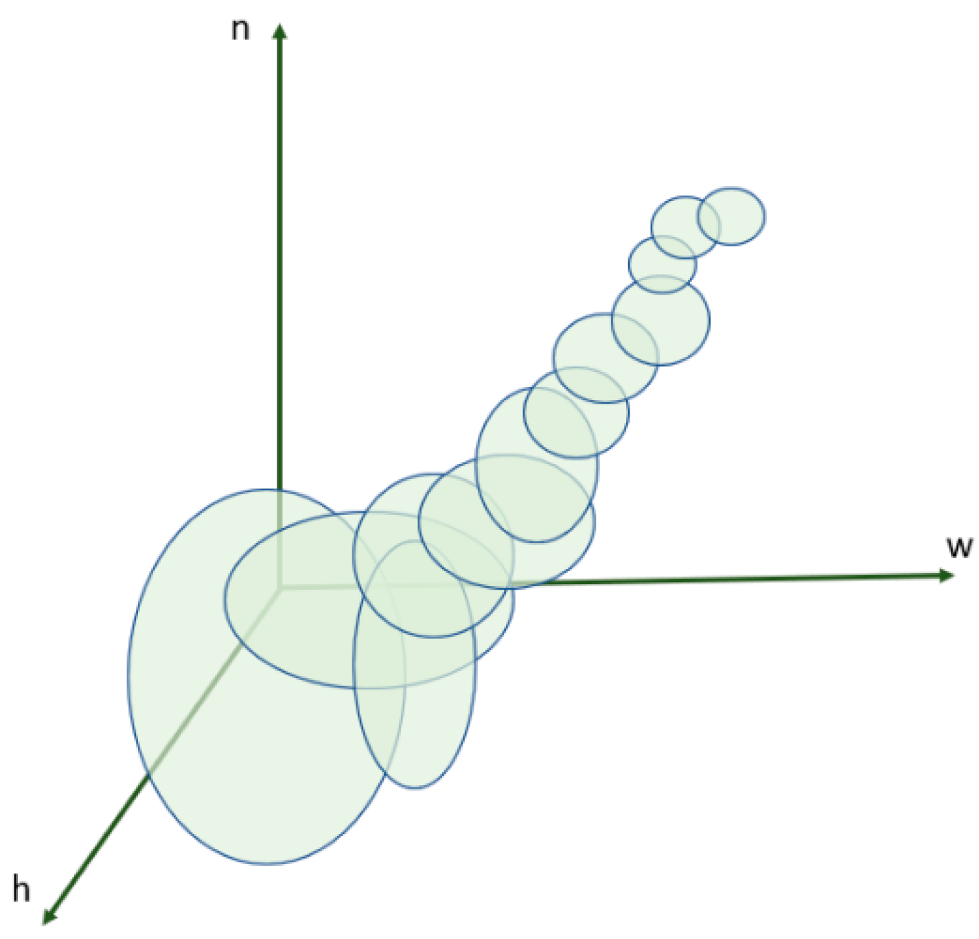
The filtering (repairing) process described above Figure 3, operates on an n-dimensional space which is not possible to show graphically. For illustrative purposes a three-dimensional depiction of the filtering process is shown in Figure 4 below, where circles or ellipses represent the search space, n is the iteration number, (w, h) are the parameters.

3. Results

The numerical and optimization algorithm described above is used in the determination of the of the optimal baffle geometries for the contact tank shown in Figure 1a,b. Since there are several intermediary results obtained during the optimization process, samples from some of the intermediary results will be presented in a sequential manner so that the reader will follow the trend towards the final optimal solution for the vertical baffle case.
For the optimal design of the vertical baffle case, the parameters given in Table 2 are randomly considered to create alternative baffle geometry sets. These sets are used in the Monte Carlo simulations of the optimization algorithm. Given the number of geometric parameters selected in Table 3 and their random placement option on nine slot locations on the baffle (Figure 1b) there are more than several thousand possible baffle configurations in the baffle geometry set. The slot heights below 10 mm and above 16 mm were eliminated by PGA algorithm. The slot width below 100 mm were eliminated by PGA algorithm. For the optimal solution the full slot width case of 230 mm resulted as the optimal design with random placement option for the slot heights yielding a specific pattern. However, for comparison of the results, finite width results are also given in the discussion below. The slot spacing below 40 mm and above 46 mm were eliminated by the PGA algorithm.

3.1. Baffle without Slots

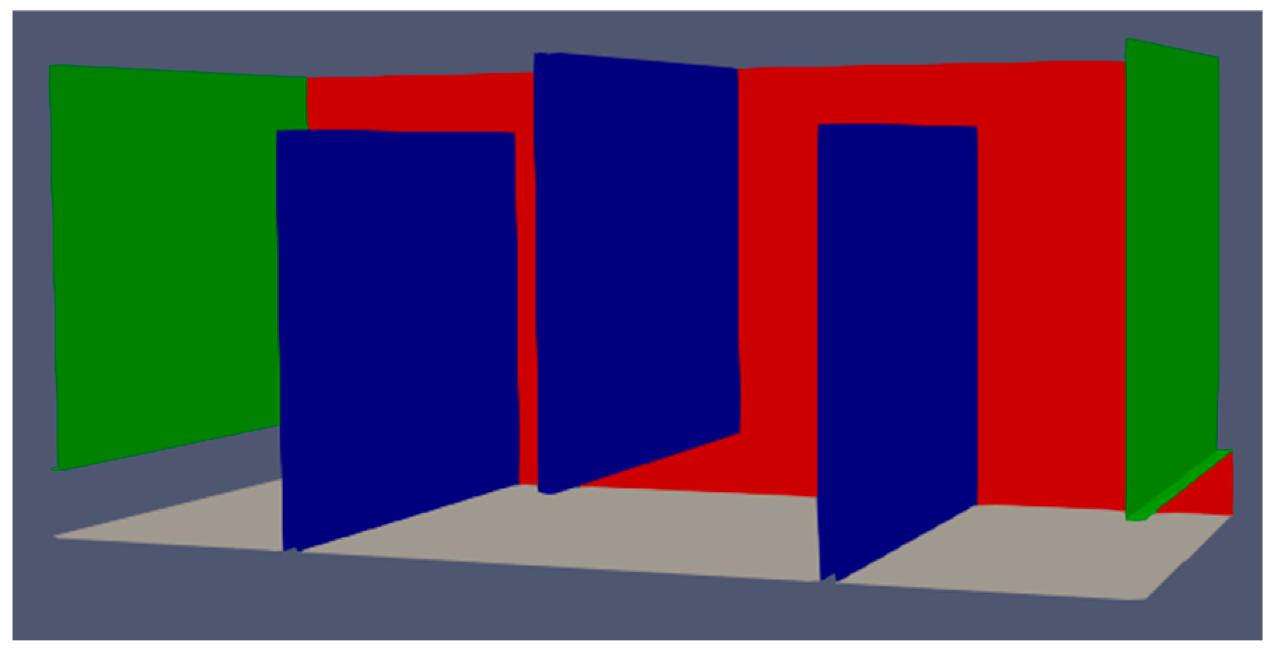
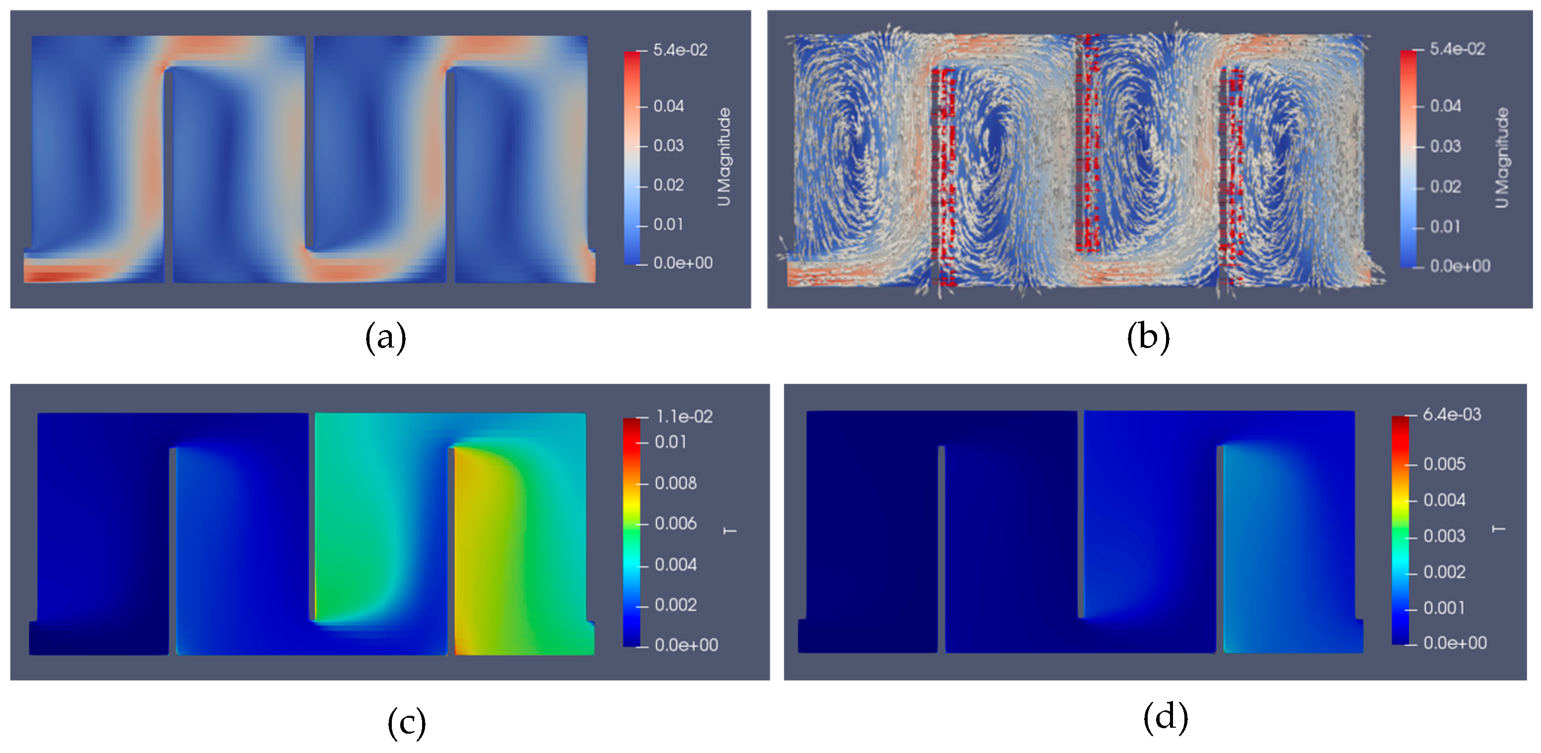
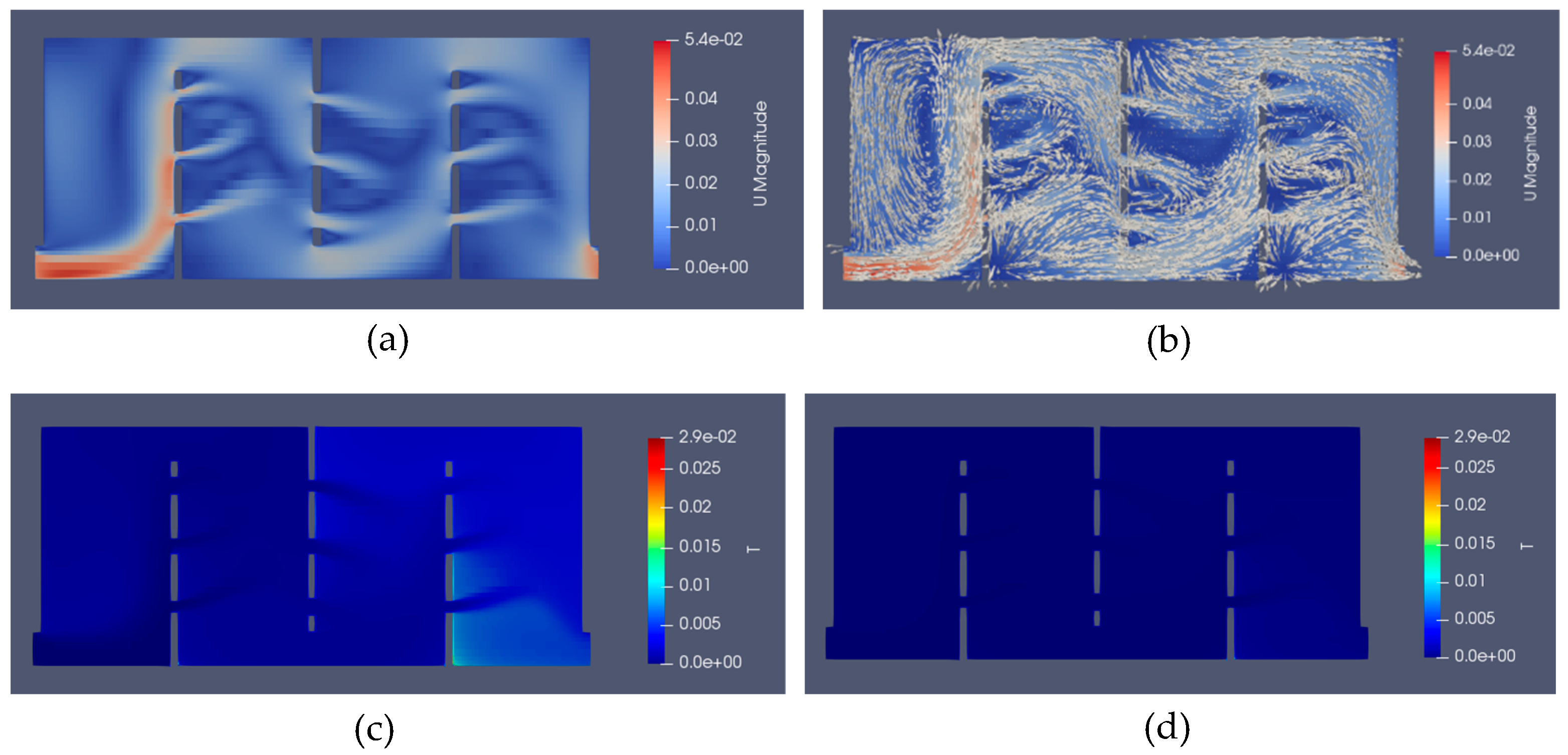
The baffles without slots case is shown Figure 5 [14]. The resulting flow and velocity configuration is shown in Figure 6 along with tracer concentration distributions for 200 s and 300 s.
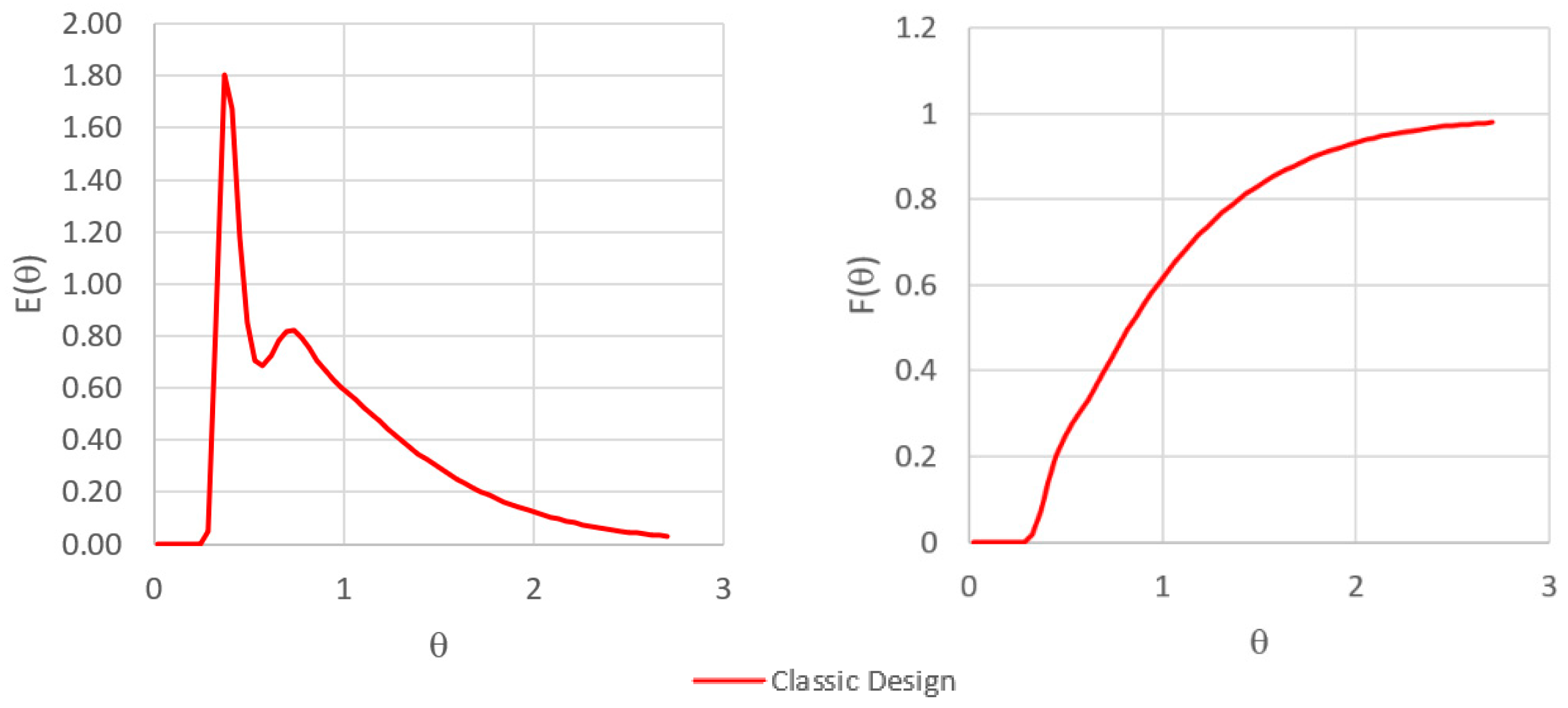
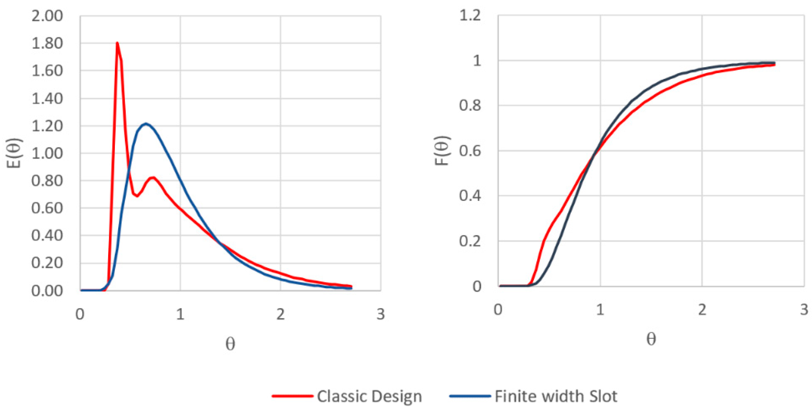
As can be seen in Figure 6a,b, the formation of jet flow zones and recirculation zones (dead zones) are clear, which are not desired in contact tank design. Concentration distributions shown in Figure 6c,d also show that important traces of the unmixed volume of water exist at 200 and 300 s. Residence time and cumulative residence time plots obtained for this case will be used as benchmark case later to evaluate the optimal baffle design obtained in the study. E(θ) (RTD) and F(θ) (CRTD) plots obtained for this case are shown in Figure 7 where the baffles without slots case is identified as the “classic design”. The AD index for this case is calculated as AD = 1.12. In the literature it is shown that the AD index is a better indicator for hydraulic and mixing efficiency of contact tanks and will be used for comparison purposes in this study [16].
The second hump seen in the E ( θ ) curve is a clear indicator of the existence of dead zones in the contact tank and should be eliminated as much as possible to produce effective mixing in the contact tank [14].

3.2. Finite Width Slot Baffle Population

As given in Table 2, a range of finite width and full width slot baffles are considered for the optimal design of the baffle geometry. A typical case of finite width baffle configurations for baffle width (w = 120 mm; h = 10, 12, 14 mm) geometry is shown in Figure 8, where (10, 12, 14 mm) slot heights are sequentially placed in up-down-up pattern on the baffle as seen in Figure 8.
Typical results for flow and velocity configuration for this case is shown in Figure 9 along with tracer concentration distributions for 200 s and 300 s.
As can be seen in Figure 9a,b, the formation of jet flow zones and recirculation zones (dead zones) has disappeared in this design. The tracer simulations indicate that desired or near desired mixing conditions are achieved at around 200 s and clearly at 300 s, as seen in Figure 9c,d, respectively. Residence time and cumulative residence time plots obtained for this case are shown in Figure 10, respectively. Figure 10 shows both the classic case and the finite slot baffle case RTD a CRTD results together for comparison purposes.
The finite width slot results given above are only a sample outcome for this population group of baffle geometries considered in this study. The results given above are included in this section to demonstrate the intermediate outcomes and they are not the optimal results that satisfy the four criterion that is defined earlier. The AD index for this case is calculated as AD = 1.16.

3.3. Full Width Slot Baffle Population

The next population of baffle geometries considered in Table 2 include the full width slot baffle geometries. A typical case of full slot baffle configurations (w = 230 mm) with thickness (h = 12, 16, 14 mm random placement) is shown in Figure 11.
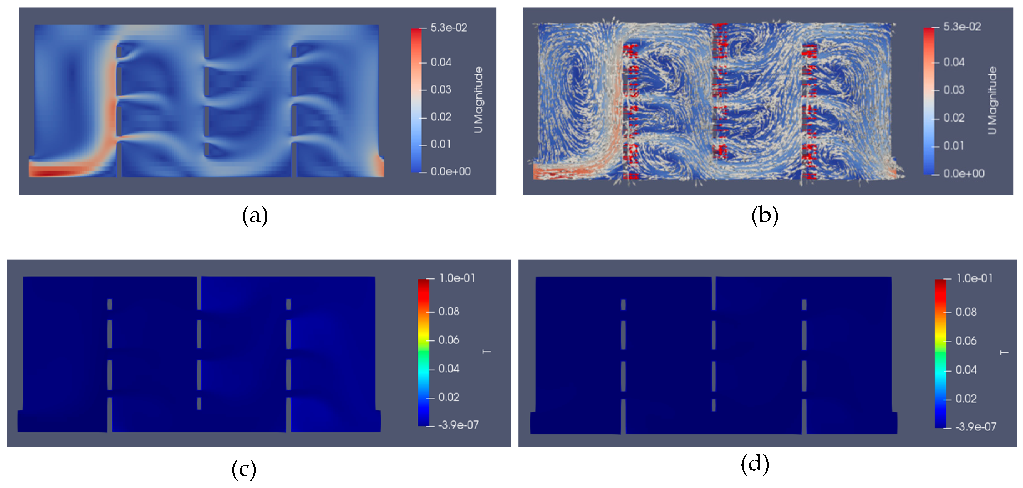
As can be seen in Figure 12a,b, the formation of jet flow zones and recirculation zones (dead zones) cannot be observed for this case as well. The tracer simulations indicate that desired mixing conditions are achieved at around 200 s and fully at 300 s, as seen in Figure 12c,d respectively. Residence time and cumulative residence time plots obtained for this case are shown in Figure 13. Figure 13 shows both the classic case, the finite slot baffle case and the full slot baffle case RTD a CRTD plots for comparison purposes.
The results given in Figure 14, Figure 15, Figure 16 and Figure 17 are sample results from the iterative optimization process. The optimal configuration of the baffle geometry is discussed in Section 3.4 below, for which the four criteria are satisfied at a certain degree but in a balanced manner which is based on the single objective function defined in Section 2.4. However, given the trend line indicated in the sequence of results presented up to this point, the full width slot baffle population seems to perform better than the finite width slot population used in the in the Monte Carlo applications. The AD index for this case is calculated as AD = 1.44, which is now at an excellent mixing category.

3.4. Optimal Baffle Geometry

The proposed methodology is used to determine the optimal baffle geometry for the four chamber three vertical baffle contact tank described in Section 2.3. This contact tank is extensively studied in the literature [4,5,12,13,14]. The baffle geometry population that is used in the genetic algorithm application are given in Table 2. The genetic algorithm parameters used in PGA application is given in Table 3 [25,26,27,28,29].
The PGA algorithm search starts with 60 random baffle geometry members. Through the application of genetic algorithm iterative processes and the PGA filtration process, new baffle geometries are generated until convergence is achieved for the objective function given in Equation (23). For illustration purposes, two intermediate baffle geometry results are given in the previous section. The final optimal baffle geometry obtained in this iterative process is the three full slot baffle geometry as given in Figure 11. The detailed characteristics of this geometry are given in Table 4 in terms of slot dimensions and the spacing between slots. The location of nine slot openings on three baffles are given in Figure 1b.
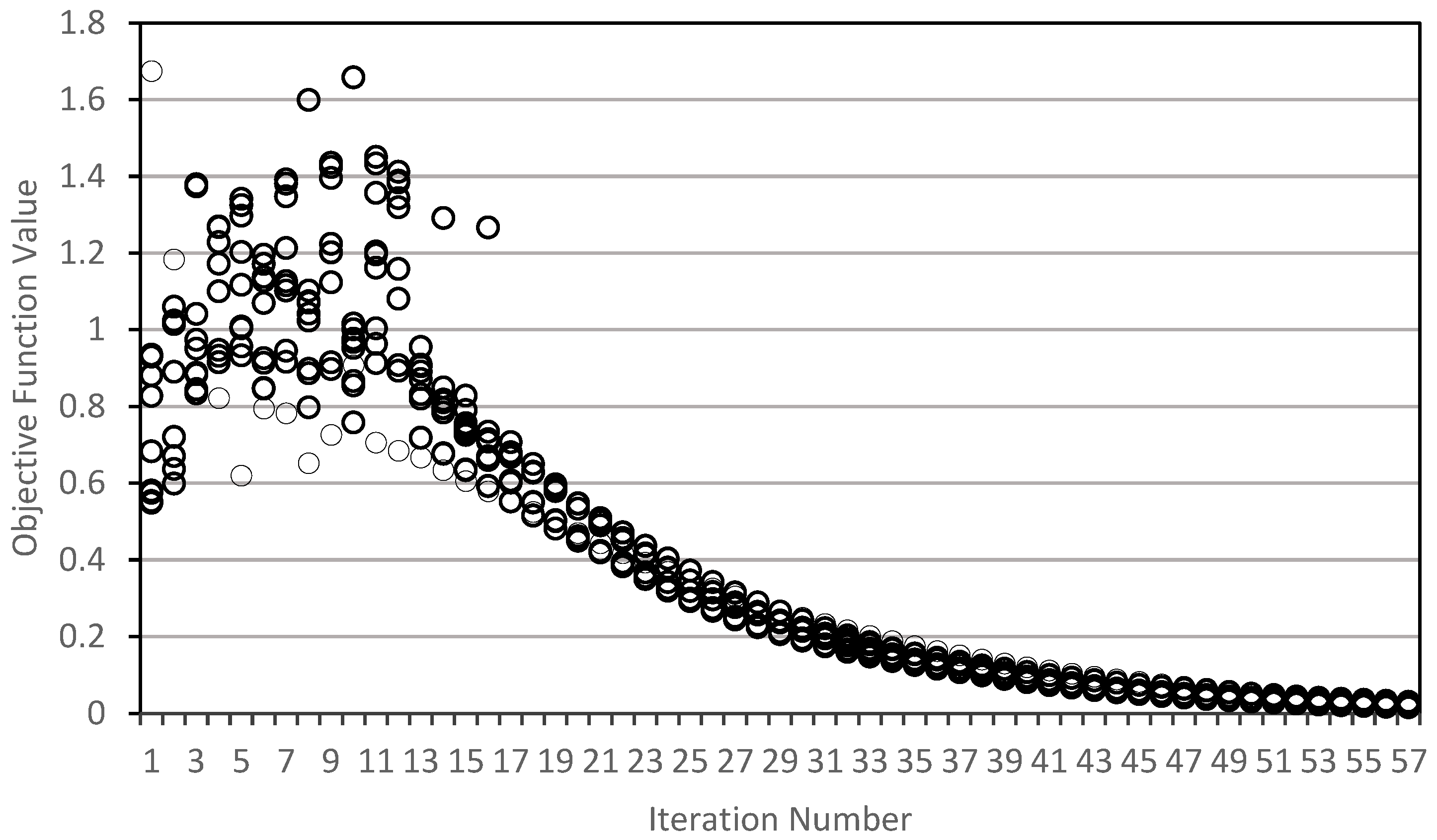
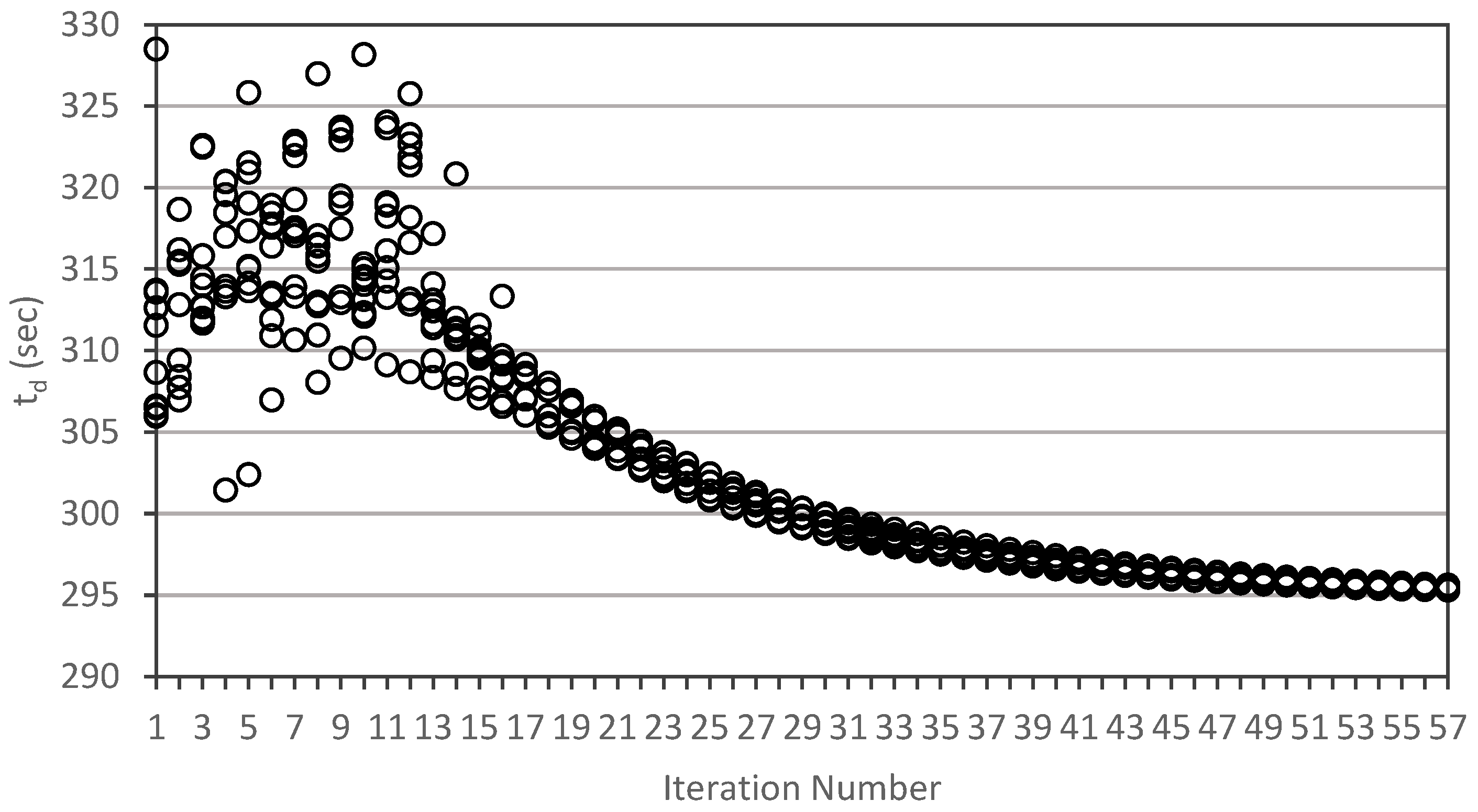
The progression of the iterative genetic algorithm solution augmented with PGA filtration process can be observed in the sequence of results given in Figure 14, Figure 15, Figure 16 and Figure 17. Sequentially the results given in these figures show the convergence pattern of each design criteria. As seen in these figures, for each case the results for each criterion start in a random scatter of criteria values and the trendline quickly converges to systematic single line pattern at about nineteen iterations as the baffle geometries are continually adjusted in a random manner following the baffle configuration patterns given in Table 2. It should be noted that only randomly selected 100 baffle geometry results are included in Figure 14, Figure 15, Figure 16 and Figure 17 to demonstrate the convergence trend in the solution.
Given the sequence of results shown in Figure 14, Figure 15, Figure 16 and Figure 17, the final optimal contact tank baffle geometry resulted in the configuration given in Table 4, which yields the minimum disinfection period of t d = 295   s (Figure 15), during which 0.0622 m3 of water is treated (Figure 16) with a reliability of r ( X ) = 0.87 (Figure 16). The convergence of the optimal results is achieved within about 57 iterations as seen in Figure 14.
The results shown above indicate that the proposed objective function performs in the desired manner yielding the appropriate minimization and maximization of the four criteria defined and included in the objective function. The PGA algorithm used effectively reduces the number of iterations and the iterative solution is obtained in about 57 iterations with minimal choice pattern achieved at about 20 iterations. This is an efficient optimization sequence given the thousands of random populations that is considered in the heuristic analysis.
The result obtained above indicates that the full slot application yielded better optimal solution when compared with the finite width slot used earlier [14]. From the perspective of fluid mixing, this outcome is not that unusual since the fluid jet mixing impact is extended on the full length of the contact tank volume as opposed to the finite length mixing impact. This eliminated the possibility of the formation of recirculation zones (dead zones) on the outer ends of the slots within the chambers.

4. Discussion

There are several important outcomes of the study reported in this paper which include: (i) the conceptual development of the multidimensional design perspective that is important to consider in the contact tank design; (ii) appropriate choice of computational and optimization formulation of the multidimensional problem developed; (iii) the development of an efficient methodology that will be used in the simulation-optimization process; and (iv) the final outcome of the determination of the optimal contact tank geometry that would achieve the desired objectives of the four design criteria for the contact tank.
The conceptual development of the multidimensional design concept reported in this study is probably the most important component of this study. In earlier studies, the contact tank design was only treated from the perspective of the improvement of the mixing efficiency of the contact tank design and the other design considerations were not included to the analysis. This was simply achieved by proposing alternative baffle configurations as reported in numerous baffle configuration design studies that appeared in the literature. However, as emphasized in this study, there are several other criteria that must be considered in an effective and efficient design of contact tanks. These criteria include the minimization of the treatment period, maximization of the treated volume within the treatment period, maximization of the mixing efficiency and finally the reliability of the proposed design in achieving all these goals within the treatment period. Thus, in this study it is emphasized that the contact tank design concept must be reformulated and treated as a multi-dimensional problem rather than a one-dimensional problem in which one only considers the mixing efficiency component.
Given the new multidimensional design perspective, the first goal is the identification of the additional dimensions of the multi-dimensional problem other than only using the mixing efficiency dimension. In this study, these dimensions are identified as criterion Z 1 , Z 2 , Z 3 and Z 4 when conservative treatment process is considered. Given this multidimensional design perspective, the next step becomes the formulation of an optimal design concept and its solution, since clearly the simple trial and error approach used in earlier studies will not yield reliable outcomes, given the number of alternative combinations that are possible within the four criteria and the sub-alternatives that are possible within each criterion.
The next step considered in this study is the effective analysis of the multi-objective problem using a single objective function approach that would combine the desired outcomes of the four criteria into a single objective function effectively. The explanation of why this would be a better approach is discussed in detail above along with the details of the steps involved in formulating the single objective function.
Following these conceptual and mathematical developments, the computational development component of the analysis is the next step that is considered in this study. This step is also very important since the computational domain is tedious and cumbersome and several refinements in the traditional computational methods are necessary. This is achieved using the simulation-optimization processes which involved the CFD analysis using OpenFOAM9 platform [23], the genetic algorithm approach [25], and the PGA analysis [27] combined in an efficient process.
All these steps are important and need to be considered in the design of contact tank geometries for efficient and effective performance of the contact tank.
Finally, the application of these steps is demonstrated for the design of a contact tank which is extensively studied in the literature. The outcome obtained resulted in the complete redesign of the contact tank baffle geometry when compared with the results of the earlier studies reported in the literature [14]. This outcome emphasizes the importance of the multi-dimensional analysis concept developed in this study. Given this outcome, and concept developed in this study, it becomes clear that analysis based on a one-dimensional optimal design, that only considers mixing efficiency in a contact tank may not yield a satisfactory design perspective for the overall performance of the contact tanks in water treatment.

5. Conclusions

The following key outcomes summarize the important contributions of the current study to the literature on contact tank design.
  • The multidimensional design concept introduced is important in the overall design of the contact tanks since it provides a platform to include multiple design criteria that would contribute to the overall performance of contact tank design beyond a one-dimensional approach of baffle geometry design to improve mixing.
  • The appropriate development of the optimization algorithm is important since a multitude of optimization solution strategies exist in the literature for the solution of multi-dimensional optimization problems, such as multi-objective approaches. The strategy recommended in this study, which is the use of a single objective function approach, performed well for the problem considered in this case without artificial controls on the final selection.
  • Simulation-optimization techniques have been previously used in the literature. The recommended CFD analysis combined with PGA assisted genetic algorithm approach provided a preferable and efficient computational platform for the application considered in this case and may be adopted in future studies.
  • The optimum contact tank design achieved that would satisfy the four design objectives in a smart manner, and using a single objective function, yielded a new contact tank baffle design that was not reported in the earlier literature. This indicates that the multidimensional analysis concept developed in this study is an important concept which may be adopted in future studies.

Funding

This research is not funded.

Institutional Review Board Statement

Not applicable.

Informed Consent Statement

Not applicable.

Data Availability Statement

Numerical results reported in this paper maybe shared by the interested parties if requested. Please contact the author.

Conflicts of Interest

The author declares no conflict of interest as the concepts and the work product reported solely belongs to the author.

References

  1. Aral, M.M. Environmental Modeling and Health Risk Analysis; Springer Publishers: Berlin/Heidelberg, Germany, 2011; 487p, ISBN 978-90-481-8607-5. [Google Scholar]
  2. Langlais, B.; Reckhow, D.A.; Brink, D.R. (Eds.) Ozone in Water Treatment: Application and Engineering; Lewis: Chelsea, MI, USA, 1991. [Google Scholar]
  3. Zhang, J.; Martinez, A.E.T.; Zhang, Q. Hydraulic efficiency in RANS of the flow in multi-chambered contactors. J. Hydraul. Eng. 2013, 139, 1150–1157. [Google Scholar] [CrossRef]
  4. Angeloudis, A.; Stoesser, T.; Falconer, R.A. Predicting the disinfection efficiency range in chlorine contact tanks through a CFD-based approach. Water Res. 2014, 60, 118–129. [Google Scholar] [CrossRef] [PubMed]
  5. Kim, D.; Elovitz, M.; Roberts, P.J.W.; Kim, J.H. Using 3D LIF to investigate and improve performance of a multi-chamber ozone contactor. J. Am. Water Works Assoc. 2010, 102, 61–70. [Google Scholar] [CrossRef]
  6. Rauen, W.B.; Lin, B.; Falconer, R.A.; Teixeira, E.C. CFD and experimental model studies for water disinfection tanks with low Reynolds number flows. Chem. Eng. J. 2008, 137, 550–560. [Google Scholar] [CrossRef]
  7. Taylor, Z.H.; Carlston, J.S.; Venayagamoorthy, S.K. Hydraulic design of baffles in disinfection contact tanks. J. Hydraul. Res. 2015, 53, 400–407. [Google Scholar] [CrossRef]
  8. Wang, H.; Falconer, R.A. Simulating disinfection processes in chlorine contact tanks using various turbulence models and high order accurate difference schemes. Water Res. 1998, 32, 1529–1543. [Google Scholar] [CrossRef]
  9. Zhang, J.; Martinez, A.E.T.; Zhang, Q. Reynolds-averaged Navier-Stokes simulation of the flow and tracer transport in a multichambered ozone contactor. J. Environ. Eng. 2013, 139, 450–454. [Google Scholar] [CrossRef]
  10. Zhang, J.; Martinez, A.E.T.; Zhang, Q.; Lei, H. Evaluating hydraulic and disinfection efficiencies of a full-scale ozone contactor using a RANS-based modeling framework. Water Res. 2014, 52, 155–167. [Google Scholar] [CrossRef]
  11. Teixeira, E.C.; Rauen, W.B. Hydrodynamic Design and Assessment of Water and Wastewater Treatment Units; CRC Press: Boca Raton, FL, USA; Taylor & Francis Group: Boca Raton, FL, USA, 2020; 101p, ISBN 9781138495890. [Google Scholar]
  12. Demirel, E.; Aral, M.M. Unified Analysis of Multi-Chamber Contact Tanks and Mixing Efficiency Based on Vorticity Field. Part I: Hydrodynamic Analysis. Water 2016, 8, 495. [Google Scholar] [CrossRef] [Green Version]
  13. Demirel, E.; Aral, M.M. Unified Analysis of Multi-Chamber Contact Tanks and Mixing Efficiency Based on Vorticity Field. Part II: Transport Analysis. Water 2016, 8, 537. [Google Scholar] [CrossRef] [Green Version]
  14. Aral, M.M.; Demirel, E. Novel slot-baffle design to improve mixing efficiency and reduce cost of disinfection in drinking water treatment. ASCE J. Environ. Eng. 2017, 143, 06017006. [Google Scholar] [CrossRef]
  15. Demirel, E.; Aral, M.M. An Efficient Contact Tank Design for Potable Water Treatment. Tek. Dergi 2018, 29, 8279–8294. [Google Scholar] [CrossRef]
  16. Demirel, E.; Aral, M.M. Performance Assessment of Efficiency Indexes for Contact Tanks. ASCE J. Environ. Eng. 2018, 144, 04018076. [Google Scholar] [CrossRef]
  17. Kizilaslan, A.M.; Demirel, E.; Aral, M.M. Effect of Porous Baffles on the Energy Performance of Contact Tanks in Water Treatment. Water 2018, 10, 1084. [Google Scholar] [CrossRef] [Green Version]
  18. Demirel, E.; Aral, M.M. Liquid Sloshing Damping in an Accelerated Tank using a Novel Slot-Baffle Design. Water 2018, 10, 1565. [Google Scholar] [CrossRef] [Green Version]
  19. Kizilaslan, M.A.; Demirel, E.; Aral, M.M. Efficiency Enhancement of Chlorine Contact Tanks in Water Treatment Plants: A Full-Scale Application. Processes 2019, 7, 551. [Google Scholar] [CrossRef] [Green Version]
  20. Demirel, E.; Aral, M.M. A Design for Vortex Suppression Downstream of a Submerged Gate. Water 2020, 12, 750. [Google Scholar] [CrossRef] [Green Version]
  21. Nasyrlayev, N.; Kizilaslan, M.A.; Kurumus, A.T.; Demirel, E.; Aral, M.M. A Perforated Baffle Design to Improve Mixing in Contact Tanks. Water 2020, 12, 1022. [Google Scholar] [CrossRef] [Green Version]
  22. Zhang, J.; Pierre, K.C.; Tejada-Martinez, A.E. Impacts of flow and tracer release unsteadiness on tracer analysis of water and wastewater treatment facilities. J. Hydraul. Eng. 2019, 145, 04019004. [Google Scholar] [CrossRef]
  23. OpenFOAM9. The OpenFOAM Foundation; OpenCFD Ltd.: Bracknell, UK, 2015. [Google Scholar]
  24. Okuducu, M.B.; Aral, M.M. Performance Analysis and Numerical Evaluation of Mixing in 3-D T-Shape Passive Micromixers. Micromach. J. Spec. Issue Passiv. Micromixers 2018, 9, 210. [Google Scholar] [CrossRef] [Green Version]
  25. Goldberg, D.E. Genetic Algorithms in Search, Optimization, and Machine Learning; Addison-Wesley: Reading, MA, USA, 1989; p. 412. [Google Scholar]
  26. Aral, M.M.; Guan, J.; Maslia, M.L. Optimal Design of Sensor Placement in Water Distribution Systems. ASCE J. Water Resour. Plan. Manag. 2010, 136, 5–18. [Google Scholar] [CrossRef]
  27. Guan, J.B.; Aral, M.M. Progressive genetic algorithm for solution of optimization problems with nonlinear equality and inequality constraints. Appl. Math. Model. 1999, 23, 329–343. [Google Scholar] [CrossRef] [Green Version]
  28. Park, C.H.; Aral, M.M. Multi-objective optimization of pumping rates and well placement in coastal aquifers. J. Hydrol. 2004, 290, 80–99. [Google Scholar] [CrossRef]
  29. Guan, J.; Aral, M.M.; Maslia, M.L.; Grayman, W.M. Identification of Contaminant Sources in Water-Distribution Systems Using Simulation-Optimization Method: A Case Study. ASCE J. Water Resour. Plan. Manag. 2006, 132, 252–262. [Google Scholar] [CrossRef]
Figure 1. Schematic view of the contact tank: (a) baffle without slots case; (b) slot-baffle case [14].
Water 14 00973 g001
Figure 2. Computational mesh generated using the blockMesh utility for one of the finite slot width cases: (a) mesh geometry used for the full contact tank; (b) left half perspective of the contact tank mesh cut at the middle of the center vertical baffle.
Water 14 00973 g002
Figure 3. Progressive Genetic Algorithm (PGA) flow chart [27,28].
Water 14 00973 g003
Figure 4. PGA filtering process in Genetic Algorithm application.
Water 14 00973 g004
Figure 5. Contact tank baffle configuration for baffles without slots.
Water 14 00973 g005
Figure 6. Velocity magnitude and concentration distributions in the contact tank for the classic design (without slot baffle case): (a) Flow distribution; (b) Flow distribution with velocity vectors; (c) Concentration distribution at 200 s; (d) Concentration distribution at 300 s.
Water 14 00973 g006
Figure 7. E(θ) and F(θ) plots (Equations (7) and (8)) obtained from tracer simulations for classic contact tank.
Water 14 00973 g007
Figure 8. Typical contact tank baffle configuration for baffles with slots (w = 120 mm, h = 10, 12, 14 mm random) case.
Water 14 00973 g008
Figure 9. Typical velocity magnitude and concentration distributions in the contact tank with finite with slots (w = 120 mm, h = 10, 12, 14 mm random) case: (a) Flow distribution; (b) Flow distribution with velocity vectors; (c) Concentration distribution at 200 s; (d) Concentration distribution at 300 s.
Water 14 00973 g009
Figure 10. E(θ) and F(θ) plots obtained from tracer simulations for contact tank with finite width slots and classic design cases.
Water 14 00973 g010
Figure 11. Typical contact tank baffle configuration for baffles with full width slots (w = 230 mm, h = 12, 16, 14 mm random placement) case.
Water 14 00973 g011
Figure 12. Typical velocity magnitude and concentration distributions in the contact tank with full width slots (w = 230 mm, h = 12, 16, 14 mm random placement) case: (a) Flow distribution; (b) Flow distribution with velocity vectors; (c) Concentration distribution at 200 s; (d) Concentration distribution at 300 s.
Water 14 00973 g012
Figure 13. E(θ) and F(θ) plots obtained from tracer simulations for contact tank with full width slots (w = 230 mm, h = 12, 16, 14 mm random) case.
Water 14 00973 g013
Figure 14. Objective function convergence trend for the optimal solution.
Water 14 00973 g014
Figure 15. Convergence trend for the parameter t d .
Water 14 00973 g015
Figure 16. Convergence trend for the reliability parameter r ( X ) .
Water 14 00973 g016
Figure 17. Convergence trend for the treated volume of water within t d period.
Water 14 00973 g017
Table 1. Boundary conditions for flow variables on the boundaries of the flow domain.
VariablesBoundary Conditions Used
Inlet RegionOutlet RegionAtmosphere BoundaryWall Regions
UmappedinletOutletsymmetryPlanenoSlip
pmappedinletOutletsymmetryPlanezeroGradient
kmappedinletOutletsymmetryPlanekqRWallFunction
εmappedinletOutletsymmetryPlaneepsilonWallFunction
nutmappedinletOutletsymmetryPlanenutkWallFunction
Table 2. Baffle geometry cases considered in the vertical baffle design.
ParametersCases Considered
Baffle 1Baffle 2Baffle 3Options
Number of Slots1, 2, 3, 41, 2, 3, 41, 2, 3, 4PGA Elim. 1, 2, 4
Finite Slot (w-mm)100, 110, 120, 160100, 110, 120, 160100, 110, 120, 160Random
Finite Slot (h-mm)10, 12, 14, 1610, 12, 14, 1610, 12, 14, 16Random
Full Slot (h-mm)10, 12, 14, 1610, 12, 14, 1610, 12, 14, 16Random
Space between slots (mm)40, 42, 44, 4640, 42, 44, 4640, 42, 44, 46Random Sym.
Table 3. Parameters used in PGA application.
ParametersPGA Parameters
Value
Population Size60
Crossover Ratio0.8
New Member Generation Ratio0.3
Elitism RatioBest Member
Mutation Ratio0.2
Maximum generation for each Subdomain40
Table 4. Optimal baffle geometry for the four-chamber contact tank.
Slot NumberOptimal Slot Geometry
(w, h) (mm)
Slot 1(230, 12)
Slot 2(230, 16)
Slot 3(230, 14)
Slot 4(230, 14)
Slot 5(230, 16)
Slot 6(230, 12)
Slot 7(230, 12)
Slot 8(230, 16)
Slot 9(230, 14)
Spacing between slots(39, 38)
Distance from base to first slot(45)
Publisher’s Note: MDPI stays neutral with regard to jurisdictional claims in published maps and institutional affiliations.