Article

Competition of Magnetic Anisotropies in Permalloy Antidot Lattices

by
Jose M. Porro
1,2,*,
Aritz Villar
1,
Carolina Redondo
3,
Natalia A. Río-López
1,
Andoni Lasheras
4,
Daniel Salazar
1,
Rafael Morales
1,2,3 and
Eduardo Fernández-Martín
1
1
BCMaterials, Basque Center for Materials, Applications and Nanostructures, 48940 Leioa, Spain
2
Ikerbasque, Basque Foundation for Science, 48009 Bilbao, Spain
3
Department of Chemical-Physics, Faculty of Science and Technology, University of the Basque Country UPV/EHU, 48940 Leioa, Spain
4
Department of Physics, Faculty of Science and Technology, University of the Basque Country UPV/EHU, 48940 Leioa, Spain
*
Author to whom correspondence should be addressed.
Magnetochemistry 2022, 8(5), 55; https://doi.org/10.3390/magnetochemistry8050055
Submission received: 2 April 2022 / Revised: 20 April 2022 / Accepted: 5 May 2022 / Published: 10 May 2022
(This article belongs to the Special Issue Micromagnetics and Magnetization Processes in Nanomagnetism)

Abstract

:
Antidot lattices made of magnetic thin films are good candidates to be employed in future magnetic recording media. In this manuscript we present a study on the effect of shape and field-induced magnetic anisotropies on the magnetization reversal of 10 nm and 50 nm thick permalloy antidot lattices. Rounded antidot square lattices were fabricated using a combination of electron beam evaporation and laser interference lithography, covering surfaces of a few cm2. We demonstrate that a magnetic anisotropy induced in the samples, as a consequence of an applied magnetic field during growth, competes with the shape anisotropy that dominates the response of the patterned thin films, and that the effect of the field-induced magnetic anisotropy scales with the thickness of the antidot thin films. Finally, we have quantified the anisotropy constant attributable to the uniaxial field-induced magnetic anisotropy in our antidot lattices. These findings are supported by micromagnetic simulations performed using MuMax3.

1. Introduction

Many current technological developments related to recording media are tied to the study and generation of novel magnetic materials in the form of thin films. These include floating solid-state thin films for dynamically reconfigurable functional nanodevices [1], thin films undergoing all-optical switching phenomena for magnetic recording media [2], thin films undergoing magnetic phase transitions [3], and the exploitation of static and dynamic magnetic properties of Heusler alloy thin films towards their implementation in recording media [4,5]. Patterned magnetic thin films are a particular subgroup of interesting magnetic materials being developed for current and future technological applications, including the study of magnetic memories through patterned topological insulator materials [6], magnetic skyrmions [7], and artificially frustrated nanostructured systems [8,9].
Antidot lattices are a particularly attractive subgroup of patterned magnetic thin films, as these provide scientists with a plethora of parameters to experiment with in order to change the material’s properties. In particular, the shape, size, lateral dimensions, choice of materials, and lattice geometries are engineerable variables that allow a fine tuning of the antidot lattice properties. Specifically, changes in geometrical parameters result in a change in the strength and profile of the stray fields [10] across the antidots, which leads to different pinning and motion of the domain walls through the lattice [11,12,13]; whereas changes in the thin film composition and/or thicknesses lead to different coupling strengths between magnetic domains [14,15,16,17].
To date, antidot thin films have been studied targeting specific scientific advances in their properties and functionalities, such as engineering their perpendicular anisotropy through material properties tuning [16,18,19,20]; combining soft and hard magnetic materials in multilayered antidot lattices to engineer their coercivity [12,13,21]; studying the propagation of magnons and spin waves through the antidot lattices [15,17,22,23,24,25,26,27,28,29,30,31,32,33]; nucleating and propagating skyrmions through the lattices [34]; enabling the antidot arrays as platforms for spintronic applications [13,19]; enabling the antidot arrays for use as monolithic microwave band-pass filters [25] or high density storage ferroelectric memories [35]. Nonetheless, there is still room for improvement in terms of engineering the properties of the magnetic materials from which the antidots are made, as this crucially affects their properties, and, therefore, their target applications. In this regard, tuning the magnetic anisotropy of a widely studied material for antidot lattices, such as permalloy, emerges as a promising way to use a cheap and soft magnetic material with anisotropy landscapes common to other harder and more expensive magnetic elements.
We studied the effect of induced competing magnetic anisotropies, namely shape- and field-induced, on the magnetization reversal of rounded antidot square lattices made of permalloy (Py, composition Ni80Fe20). Antidot lattices with rounded geometries and with two different thicknesses, 10 nm and 50 nm, were grown simultaneously alongside non-patterned sister thin films for comparison purposes. The antidot lattices and non-patterned thin films were grown with and without an in situ applied magnetic field on the substrate during growth. We demonstrated that the magnetic anisotropy induced in the samples as a consequence of the applied field during growth is transferred onto the antidot lattices, even though the shape anisotropy dominates the magnetic response of the patterned thin films. These results are accompanied by micromagnetic simulations that qualitatively resemble the experimentally observed behavior of the antidot lattices, which also provides information about the magnetic domain configurations upon magnetization reversal of the antidots.

2. Materials and Methods

The samples we studied were fabricated using electron beam evaporation in the case of the non-patterned thin films, and a combination of electron beam evaporation and laser interference lithography in the case of the antidot films [36]. For the resist template, an antireflective coating layer (WIDE-8B, approximately 80 nm thick, commercially available from Brewer Science Inc., Rolla, MO, USA) followed by a negative resist (TSMR-IN027, approximately 200 nm thick, commercially available from Tokyo Ohka Koygo Co., Ltd., Tokyo, Japan) were both spun-coated on top of Si (100) substrates. Subsequently, they were double-exposed to a He:Cd laser with a wavelength of 325 nm, followed by a developing process of the resist on AZ726 MIF. Py thin films with thicknesses of 10 nm and 50 nm were deposited using electron beam evaporation, followed by a 4 nm thick Al capping layer to prevent oxidation. A lift-off process including ultrasound bath sonication during immersion in N-Methyl-2-pyrrolidone (NMP) at 120 °C resulted in antidot lattices covering surfaces of a few cm2. The resulting antidot lattices are shown in Figure 1. During the thin film deposition process resist-free Si (100) substrates were also covered with Py and Al, resulting in non-patterned thin films with the same thicknesses as those of the antidot lattices; i.e., 10 nm Py/4 nm Al, and 50 nm Py/4 nm Al.
The shapes and sizes of the antidot lattices were analyzed using scanning electron microscopy (SEM) using a JEOL JSM-7000F (JEOL, Tokyo, Japan). Vibrating sample magnetometry was used to record room temperature hysteresis loops using a Microsense EZ VSM (MicroSense, Lowell, MA, USA).
Micromagnetic simulations were performed using MuMax3 software [37]. Simulated hysteresis loops at room temperature were obtained for antidot shapes resembling those of the lattices observed in the SEM images presented in Figure 1, by making simulation masks with similar shapes, allowing a far more realistic simulation process. Both the 10 nm and the 50 nm thick Py antidot lattices were simulated using 2D periodic boundary conditions (PBC) with the following parameters: magnetization saturation MS = 860 × 103 A/m, exchange coupling constant A = 13 × 10−12 J/m, damping constant α = 0.02, PBCs (2,2,0), periodicity 1200 nm, and unit cell size 5 × 5 × 5 nm3, smaller than the exchange length of Py [38]. The intentional introduction of edge roughness using a mask extracted from the SEM images presented in Figure 1 does not result in critical changes in the simulation results, while they significantly increase the required computation times. The applied field was simulated to be 1° off the lattice axis to account for imperfect field alignment in the real experiments. A field-induced uniaxial magnetic anisotropy with a value of Ku = 500 J/m3 was employed for the simulations. The choice of this value is justified in the Results and Discussion section of this manuscript.

3. Results and Discussion

SEM images of the antidot lattices studied in the present manuscript are shown in Figure 1. Figure 1a,b are SEM images of the 10 nm thick antidot lattices; Figure 1c,d correspond to images of the 50 nm thick ones. Both lattices possess periodicities of 1.2 μm from center-to-center of neighboring antidots. The diameters of the antidots are approximately 750 nm. The black shadowed regions of the inside of the antidots correspond to non-magnetic polymeric resist leftovers; their presence does not influence the behavior of the antidot lattices. The difference in the antidot roundness is attributed to slightly different exposition and developing times during the nanofabrication processes. Very small variations in the exposure time to the laser beam and/or the developing time of the resist after exposure can affect pattern sizes and shapes [36,39].
As mentioned in the Materials and Methods section, when the Py and Al layers were deposited during the nanofabrication process of the antidot lattices, patterned and non-patterned thin films were grown with a magnetic field of 500 Oe applied parallel to one side of the substrates, and, consequently, to one lattice axis. This will allow for a direct comparison between the magnetic properties of the antidot lattices and of pristine thin films with identical compositions, so that any changes can be directly attributed to competing anisotropies in the antidot lattices.
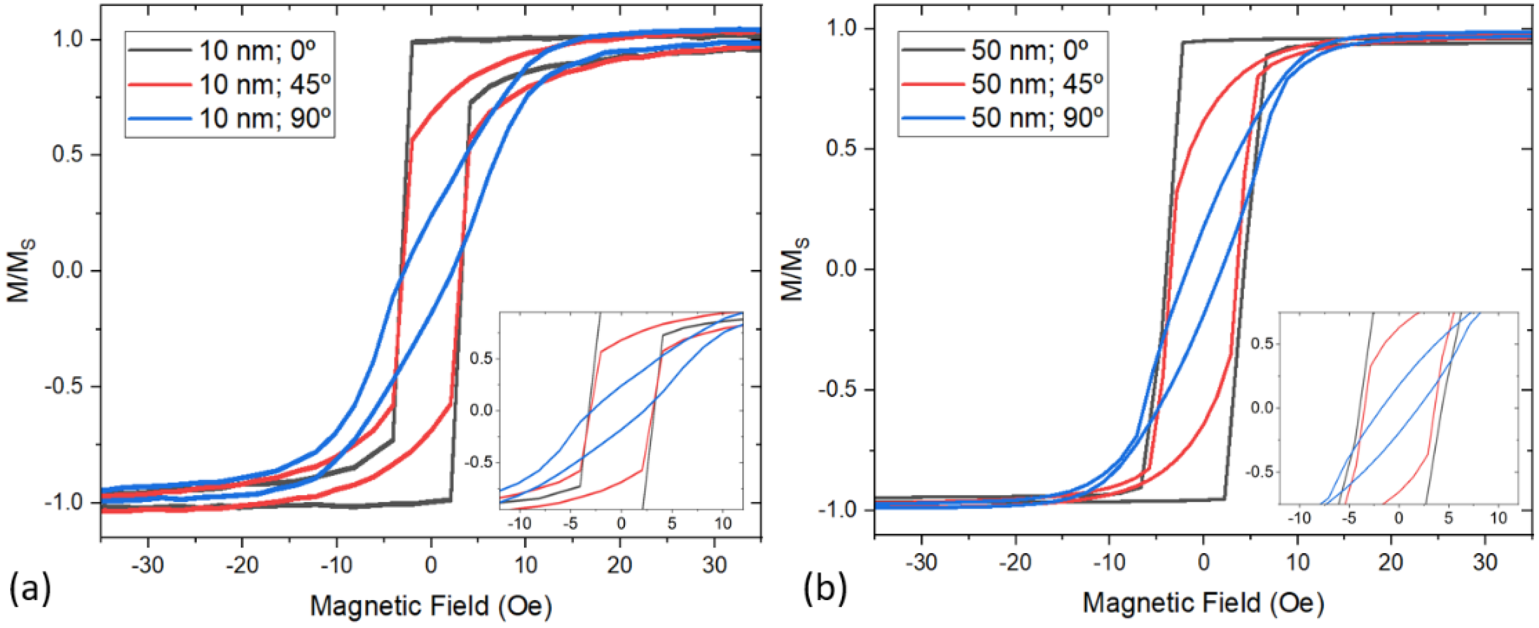
Room temperature hysteresis loops of the continuous thin films recorded using VSM magnetometry are presented in Figure 2. To analyze any possible anisotropy induced in the samples, the hysteresis loops were recorded at three different angles (0°, 45°, and 90°) from the direction of the applied field during growth. Figure 2a shows the hysteresis loops corresponding to the 10 nm thick film; Figure 2b, shows the hysteresis loops corresponding to the 50 nm thick film. As deducted from the measurements presented in Figure 2, the application of a magnetic field during thin film growth induces a hard axis at 90°, perpendicular to the direction of the applied field during growth. While the coercive field (HC) remains unaffected in the 10 nm thick film, irrespective of the applied field direction, the 50 nm thick film presents a reduction in HC of about 25% from the one along the hard axis (from HC,0°= 4 Oe to HC,90°= 3 Oe), on the easy axis. This is consistent with observations in Py thin films, where the developed anisotropy as a consequence of the applied field during thin film growth decreases with the film thickness, and vanishes at thicknesses of approximately 10 nm [40]. We can estimate the uniaxial anisotropy constant of the field-induced anisotropy by calculating the area of the hysteresis loops measured along the induced hard axes. According to the Stoner–Wohlfarth model of coherent rotation of domains [41], knowing that Ms = 860 × 103 A/m for permalloy, and using the saturating field of that hysteresis loop as input, we obtain a field-induced uniaxial anisotropy constant Ku ≈ 430 J/m3.
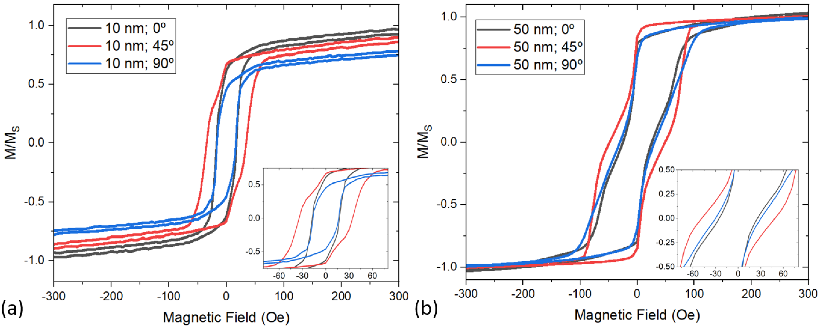
The room temperature hysteresis loops recorded from the antidot lattices are presented in Figure 3 as a function of the applied field angle with respect to the direction of the applied field during growth. Figure 3a shows the 10 nm thick antidot lattice hysteresis loops, while Figure 3b shows the 50 nm thick antidot lattice hysteresis loops. The first remarkable difference is that the antidots present a crossover in the anisotropy of easy and hard axis configuration, from a 90° angle between them in the thin films to a 45° angle in the antidot lattices. This behavior is attributed to the origin of the main magnetic anisotropy contribution. While in the thin films the field-induced anisotropy dominates, thus resulting in a magnetic easy axis along the growth field direction (0°) and a hard one perpendicular to it (90°), in the antidot lattices the magnetic shape anisotropy takes over the field-induced one, thus modifying the easy and hard axis configuration landscape, and resulting in the observed 45° angle between axes. This is in good agreement with previously studied antidot square lattices, where the easy and hard axes display a 45° periodicity [42]. Nonetheless, the presence of the field-induced magnetic anisotropy is still noticeable in the antidot lattices; the 50 nm thick sample has HC,90° = 30 Oe when the field is applied at 90°, while HC,0° = 24 Oe when it is applied along 0°. This is a reduction of ~20% in HC due to the field-induced magnetic anisotropy. The coercive fields measured at 0° and 90° in the 10 nm thick antidot lattice are indistinguishable, which is in good agreement with the results observed for the non-patterned sister thin film with similar thickness.
As derived from a direct inspection of the hysteresis loops presented in Figure 3, the magnetization reversal on both antidot lattices takes place in a two-step process, indicated by the jumps observed in the hysteresis loops. There is a noticeable difference between the 10 nm and 50 nm thick antidot lattices. For the 10 nm thick lattice, the jumps on the hysteresis loops are sharper; the 50 nm thick lattice presents smoother jumps. This is attributed to shape anisotropy, which affects the pinning of domains and domain walls within the antidots: the 10 nm thick lattice presents a sharper and uniform antidot geometry, thus resulting in a narrower distribution of the domain pinning and depinning fields, whereas the 50 nm thick lattice presents a more rounded and less uniform antidot geometry, leading to a wider distribution of domain pinning and depinning fields [43]. The magnetization reversal mechanism observed in our antidot lattices is similar to that observed in bicomponent antidots [44] or stadium shaped antidots [43].
To better understand the magnetization reversal process in our antidot lattices, as well as to quantify the field induced anisotropy during growth, micromagnetic simulations have been performed using MuMax3 [37]. Details about the specific simulation parameters and methodology followed are described in the Materials and Methods section. The simulated hysteresis loops for the two antidot lattices studied in the present work are shown in Figure 4, together with insets of specific interesting magnetic configuration states at applied fields marked on the hysteresis loops. As observed from the calculated loops, the simulations on the antidot lattices are in good qualitative agreement with the experimentally measured hysteresis loops presented in Figure 3. The divergences between the shapes of the simulated and recorded hysteresis loops, which are evident for the 50 nm thick antidot lattice, correspond to much smoother magnetization jumps on the experimental loops with respect to the simulated ones. By inspecting the metastable magnetization states that arise from the simulations of the hysteresis loops, we can confirm that they are related to the shape anisotropy of the lattices induced by the real shape of the antidots; sharp jumps in the simulation are due to perfect shapes of the antidots, whereas smooth jumps in the hysteresis loops originate in the non-uniformity of the shapes of the antidots within the lattices. This results in a smooth series of domain wall depinning processes, while in the ideal case of perfect uniform antidot shapes (which is the simulated one), a sharp all-at-once depinning process of the domains takes place, which is evident from the sharp magnetization jumps on the hysteresis loops. Similar to the behavior of the antidot lattices, simulations also account for the higher HC when the field is applied at 45°. Note that M/MS along the 45° direction is a factor of 0.70 times lower than that along the 0° and 90° directions. This is because what is obtained from the simulations at 45° is the projection of M along MX, which is at an angle of 45° with respect to M.
In addition to the understanding of the magnetization reversal process in the antidot lattices, simulations also provide us with a method to quantify the field-induced anisotropy in the lattices as a consequence of the application of a magnetic field during the thin film growth process. This can be accomplished by varying the uniaxial anisotropy constant, Ku, within the parameters of the micromagnetic simulations. We found that higher coercive fields at 90° away from the direction of the field applied during growth start to develop for Ku values of approximately 450–500 J/m3 for the 50 nm thick antidot lattices. This results in an increase in HC on the 90° hysteresis loop of approximately 20% of HC along 0°. A similar Ku value employed in the simulation of the 10 nm thick antidot lattices does not yield any difference in HC at 0° and 90°. This is in good agreement with our experimental observations, thus concluding that the field-induced uniaxial anisotropy constant value in our antidot lattices is similar to the one calculated from our experimental measurements (Ku ≈ 430 J/m3).

4. Conclusions

We investigated the effect of a field-induced uniaxial magnetic anisotropy on the anisotropy landscape, and the magnetization reversal processes of antidot lattices of different thicknesses made of permalloy. The hysteresis loops of the antidot lattices show a crossover in the anisotropy axes landscape, from a 90° field-induced easy-to-hard axis angular distribution in Py thin films to a 45° axis angular distribution one in the antidot lattices. Although the 45° angular difference between easy and hard axes is well known in square antidot lattices, here we observe that at 90° from the direction of the applied field during growth of the lattices, which should correspond to an easy axis in a standard square antidot lattice, the coercive field measured from the hysteresis loops is approximately 20% higher than the one measured at 0°. This is due to the contribution of the field-induced anisotropy to the total magnetic anisotropy of the sample. Simulations on antidot lattices with similar shapes and dimensions are in good agreement with the experimental results, and provide us with information about magnetic domain configurations during the magnetization reversal process. Finally, we have quantified the field-induced uniaxial anisotropy constant to be Ku ≈ 430 J/m3, which is in good agreement with the anisotropy constant employed in simulations that resemble the obtained experimental results. These results present a promising path towards magnetic anisotropy engineering of antidot lattices in order to tune their magnetic responses so that they can meet specific future technology demands.

Author Contributions

Conceptualization, J.M.P., A.L., R.M. and E.F.-M.; methodology, J.M.P., R.M. and E.F.-M.; samples growth: A.V. and C.R.; measurements, J.M.P., A.V., N.A.R.-L. and D.S.; micromagnetic simulations, J.M.P. and E.F.-M.; interpretation, J.M.P., R.M. and E.F.-M.; writing—original draft preparation, J.M.P.; writing—review and editing, J.M.P., A.V., C.R., N.A.R.-L., A.L., D.S., R.M. and E.F.-M. All authors have read and agreed to the published version of the manuscript.

Funding

We acknowledge financial support from the department of Education of the Basque Government through the PIBA project call (PIBA_2021_1_0051). A.V. and N.A.R.-L. acknowledge funding from the Basque Government Pre-doctoral fellowship program. R.M. and C.R. acknowledge funding from MCIN/ AEI/10.13039/501100011033/ under grant no. PID2019-104604RB-C33.

Data Availability Statement

Data are available from the authors upon reasonable request.

Acknowledgments

The authors would like to thank the technical and human support provided by SGIker units of Electron microscopy and Magnetic measurements (UPV/EHU/ERDF, EU). We gratefully acknowledge the support of NVIDIA Corporation with the donation of the NVIDIA QUADRO P6000 GPU used for this research.

Conflicts of Interest

The authors declare no conflict of interest.

References

  1. Yan, Z.; Zhang, Z.; Wu, W.; Ji, X.; Sun, S.; Jiang, Y.; Tan, C.C.; Yang, L.; Chong, C.T.; Qiu, C.W.; et al. Floating solid-state thin films with dynamic structural colour. Nat. Nanotechnol. 2021, 16, 795–801. [Google Scholar] [CrossRef] [PubMed]
  2. Wang, S.; Wei, C.; Feng, Y.; Cao, H.; Li, W.; Cao, Y.; Guan, B.O.; Tsukamoto, A.; Kirilyuk, A.; Kimel, A.V.; et al. Dual-shot dynamics and ultimate frequency of all-optical magnetic recording on GdFeCo. Light Sci. Appl. 2021, 10, 1–8. [Google Scholar] [CrossRef] [PubMed]
  3. Komlev, A.S.; Karpenkov, D.Y.; Kiselev, D.A.; Ilina, T.S.; Chirkova, A.; Gimaev, R.R.; Usami, T.; Taniyama, T.; Zverev, V.I.; Perov, N.S. Ferromagnetic phase nucleation and its growth evolution in FeRh thin films. J. Alloys Compd. 2021, 874, 159924. [Google Scholar] [CrossRef]
  4. Alexandrakis, V.; Rodríguez-Aseguinolaza, I.; Anastasakos-Paraskevopoulos, D.; Barandiarán, J.M.; Chernenko, V.; Porro, J.M. Spontaneous Zero-Field Cooling Exchange Bias in Ni-Co-Mn-Sn Metamagnetic Heusler Sputtered Film. Nanomaterials 2021, 11, 2188. [Google Scholar] [CrossRef] [PubMed]
  5. Chumak, O.M.; Pacewicz, A.; Lynnyk, A.; Salski, B.; Yamamoto, T.; Seki, T.; Domagala, J.Z.; Głowiński, H.; Takanashi, K.; Baczewski, L.T.; et al. Magnetoelastic interactions and magnetic damping in Co2Fe0.4Mn0.6Si and Co2FeGa0.5Ge0.5 Heusler alloys thin films for spintronic applications. Sci. Rep. 2021, 11, 7608. [Google Scholar] [CrossRef]
  6. Wu, H.; Chen, A.; Zhang, P.; He, H.; Nance, J.; Guo, C.; Sasaki, J.; Shirokura, T.; Hai, P.N.; Fang, B.; et al. Magnetic memory driven by topological insulators. Nat. Commun. 2021, 12, 6251. [Google Scholar] [CrossRef] [PubMed]
  7. Fert, A.; Cros, V.; Sampaio, J. Skyrmions on the track. Nat. Nanotechnol. 2013, 8, 152–156. [Google Scholar] [CrossRef]
  8. Porro, J.M.; Morley, S.A.; Venero, D.A.; Macêdo, R.; Rosamond, M.C.; Linfield, E.H.; Stamps, R.L.; Marrows, C.H.; Langridge, S. Magnetization dynamics of weakly interacting sub-100 nm square artificial spin ices. Sci. Rep. 2019, 9, 19967. [Google Scholar] [CrossRef]
  9. Morley, S.A.; Porro, J.M.; Hrabec, A.; Rosamond, M.C.; Venero, D.A.; Linfield, E.H.; Burnell, G.; Im, M.Y.; Fischer, P.; Langridge, S.; et al. Thermally and field-driven mobility of emergent magnetic charges in square artificial spin ice. Sci. Rep. 2019, 9, 15989. [Google Scholar] [CrossRef] [Green Version]
  10. Porro, J.M.; Berger, A.; Grimsditch, M.; Metlushko, V.; Ilic, B.; Vavassori, P. Effect of spatially asymmetric dipolar interactions in the magnetization reversal of closely spaced ferromagnetic nanoisland arrays. J. Appl. Phys. 2012, 111, 07B913. [Google Scholar] [CrossRef]
  11. Wang, T.Y.; Han, H.S.; Su, C.; Li, Q.; Yang, M.; Chao, W.; Zhang, X.; Hwang, C.; Zettl, A.; Im, M.Y.; et al. Magnetic anisotropy in permalloy antidot square lattice. J. Magn. Magn. Mater. 2022, 544, 168680. [Google Scholar] [CrossRef]
  12. Kaidatzis, A.; del Real, R.P.; Alvaro, R.; Niarchos, D.; Vázquez, M.; García-Martín, J.M. Nanopatterned hard/soft bilayer magnetic antidot arrays with long-range periodicity. J. Magn. Magn. Mater. 2020, 498, 166142. [Google Scholar] [CrossRef]
  13. Salaheldeen, M.; Martínez-Goyeneche, L.; Álvarez-Alonso, P.; Fernández, A. Enhancement the perpendicular magnetic anisotropy of nanopatterned hard/soft bilayer magnetic antidot arrays for spintronic application. Nanotechnology 2020, 31, 485708. [Google Scholar] [CrossRef] [PubMed]
  14. Heyderman, L.J.; Nolting, F.; Backes, D.; Czekaj, S.; Lopez-Diaz, L.; Kläui, M.; Rüdiger, U.; Vaz, C.A.F.; Bland, J.A.C.; Matelon, R.J.; et al. Magnetization reversal in cobalt antidot arrays. Phys. Rev. B-Condens. Matter Mater. Phys. 2006, 73, 214429. [Google Scholar] [CrossRef] [Green Version]
  15. Tse, D.H.Y.; Steinmuller, S.J.; Trypiniotis, T.; Anderson, D.; Jones, G.A.C.; Bland, J.A.C.; Barnes, C.H.W. Static and dynamic magnetic properties of Ni80 Fe20 square antidot arrays. Phys. Rev. B-Condens. Matter Mater. Phys. 2009, 79, 054426. [Google Scholar] [CrossRef] [Green Version]
  16. Rahman, M.T.; Shams, N.N.; Lai, C.H.; Fidler, J.; Suess, D. Co/Pt perpendicular antidot arrays with engineered feature size and magnetic properties fabricated on anodic aluminum oxide templates. Phys. Rev. B-Condens. Matter Mater. Phys. 2010, 81, 014418. [Google Scholar] [CrossRef]
  17. Liu, X.M.; Ding, J.; Adeyeye, A.O. Magnetization dynamics and reversal mechanism of Fe filled Ni80Fe20 antidot nanostructures. Appl. Phys. Lett. 2012, 100, 242411. [Google Scholar] [CrossRef]
  18. Krupinski, M.; Sobieszczyk, P.; Zieliński, P.; Marszałek, M. Magnetic reversal in perpendicularly magnetized antidot arrays with intrinsic and extrinsic defects. Sci. Rep. 2019, 9, 13276. [Google Scholar] [CrossRef] [Green Version]
  19. Salaheldeen, M.; Méndez, M.; Vega, V.; Fernández, A.; Prida, V.M. Tuning Nanohole Sizes in Ni Hexagonal Antidot Arrays: Large Perpendicular Magnetic Anisotropy for Spintronic Applications. ACS Appl. Nano Mater. 2019, 2, 1866–1875. [Google Scholar] [CrossRef]
  20. Salaheldeen, M.; Vega, V.; Ibabe, A.; Jaafar, M.; Asenjo, A.; Fernandez, A.; Prida, V.M. Tailoring of perpendicular magnetic anisotropy in Dy13Fe87 thin films with hexagonal antidot lattice nanostructure. Nanomaterials 2018, 8, 227. [Google Scholar] [CrossRef] [Green Version]
  21. Béron, F.; Kaidatzis, A.; Velo, M.F.; Arzuza, L.C.C.; Palmero, E.M.; del Real, R.P.; Niarchos, D.; Pirota, K.R.; García-Martín, J.M. Nanometer Scale Hard/Soft Bilayer Magnetic Antidots. Nanoscale Res. Lett. 2016, 11, 86. [Google Scholar] [CrossRef] [PubMed] [Green Version]
  22. Challab, N.; Faurie, D.; Haboussi, M.; Adeyeye, A.O.; Zighem, F. Differentiated Strain-Control of Localized Magnetic Modes in Antidot Arrays. ACS Appl. Mater. Interfaces 2021, 13, 29906–29915. [Google Scholar] [CrossRef] [PubMed]
  23. Pan, S.; Mondal, S.; Zelent, M.; Szwierz, R.; Pal, S.; Hellwig, O.; Krawczyk, M.; Barman, A. Edge localization of spin waves in antidot multilayers with perpendicular magnetic anisotropy. Phys. Rev. B 2020, 101, 014403. [Google Scholar] [CrossRef] [Green Version]
  24. Choudhury, S.; Barman, S.; Otani, Y.C.; Barman, A. Controlled evolution of spin waves in unconventional defective honeycomb antidot lattices. J. Magn. Magn. Mater. 2019, 489, 165408. [Google Scholar] [CrossRef]
  25. Kuanr, B.K.; Veerakumar, V.; Camley, R.E.; Celinski, Z. Permalloy (NiFe) nanometer square-antidot arrays: Dynamic modes and use as a monolithic microwave band-pass filter. J. Magn. Magn. Mater. 2019, 484, 272–278. [Google Scholar] [CrossRef]
  26. Gubbiotti, G.; Montoncello, F.; Tacchi, S.; Madami, M.; Carlotti, G.; Giovannini, L.; Ding, J.; Adeyeye, A.O. Angle-resolved spin wave band diagrams of square antidot lattices studied by Brillouin light scattering. Appl. Phys. Lett. 2015, 106, 262406. [Google Scholar] [CrossRef]
  27. Kumar, D.; Sabareesan, P.; Wang, W.; Fangohr, H.; Barman, A. Effect of hole shape on spin-wave band structure in one-dimensional magnonic antidot waveguide. J. Appl. Phys. 2013, 114, 023910. [Google Scholar] [CrossRef] [Green Version]
  28. Mandal, R.; Saha, S.; Kumar, D.; Barman, S.; Pal, S.; Das, K.; Raychaudhuri, A.K.; Fukuma, Y.; Otani, Y.; Barman, A. Optically induced tunable magnetization dynamics in nanoscale Co antidot lattices. ACS Nano 2012, 6, 3397–3403. [Google Scholar] [CrossRef]
  29. Ding, J.; Tripathy, D.; Adeyeye, A.O. Dynamic response of antidot nanostructures with alternating hole diameters. EPL 2012, 98, 16004. [Google Scholar] [CrossRef]
  30. Duerr, G.; Madami, M.; Neusser, S.; Tacchi, S.; Gubbiotti, G.; Carlotti, G.; Grundler, D. Spatial control of spin-wave modes in Ni80Fe20 antidot lattices by embedded Co nanodisks. Appl. Phys. Lett. 2011, 99, 202502. [Google Scholar] [CrossRef] [Green Version]
  31. Ulrichs, H.; Lenk, B.; Münzenberg, M. Magnonic spin-wave modes in CoFeB antidot lattices. Appl. Phys. Lett. 2010, 97, 092506. [Google Scholar] [CrossRef] [Green Version]
  32. Neusser, S.; Botters, B.; Becherer, M.; Schmitt-Landsiedel, D.; Grundler, D. Spin-wave localization between nearest and next-nearest neighboring holes in an antidot lattice. Appl. Phys. Lett. 2008, 93, 122501. [Google Scholar] [CrossRef]
  33. Martyshkin, A.A.; Odintsov, S.A.; Gubanova, Y.A.; Beginin, E.N.; Sheshukova, S.E.; Nikitov, S.A.; Sadovnikov, A.V. Controlled Spin-Wave Transport in a Magnon-Crystal Structure with a One-Dimensional Array of Holes. JETP Lett. 2019, 110, 533–539. [Google Scholar] [CrossRef]
  34. Feilhauer, J.; Saha, S.; Tobik, J.; Zelent, M.; Heyderman, L.J.; Mruczkiewicz, M. Controlled motion of skyrmions in a magnetic antidot lattice. Phys. Rev. B 2020, 102, 184425. [Google Scholar] [CrossRef]
  35. Abbas, S.K.; Saleem, M.; Naseem, S.; Riaz, S.; Atiq, S. Synthesis of Ni80Fe20 permalloy antidots for high storage ferroelectric memories. Mater. Lett. 2020, 271, 127852. [Google Scholar] [CrossRef]
  36. Silva, A.S.; Hierro-Rodriguez, A.; Bunyaev, S.A.; Kakazei, G.N.; Dobrovolskiy, O.V.; Redondo, C.; Morales, R.; Crespo, H.; Navas, D. Magnetic properties of permalloy antidot array fabricated by interference lithography. AIP Adv. 2019, 9, 035136. [Google Scholar] [CrossRef] [Green Version]
  37. Vansteenkiste, A.; Leliaert, J.; Dvornik, M.; Helsen, M.; Garcia-Sanchez, F.; Van Waeyenberge, B. The design and verification of MuMax3. AIP Adv. 2014, 4, 107133. [Google Scholar] [CrossRef] [Green Version]
  38. Abo, G.S.; Hong, Y.K.; Park, J.; Lee, J.; Lee, W.; Choi, B.C. Definition of magnetic exchange length. IEEE Trans. Magn. 2013, 49, 4937–4939. [Google Scholar] [CrossRef]
  39. Rodriguez, A.; Echeverría, M.; Ellman, M.; Perez, N.; Verevkin, Y.K.; Peng, C.S.; Berthou, T.; Wang, Z.; Ayerdi, I.; Savall, J.; et al. Laser interference lithography for nanoscale structuring of materials: From laboratory to industry. Microelectron. Eng. 2009, 86, 937–940. [Google Scholar] [CrossRef]
  40. Goto, M.; Tange, H.; Kamimori, T. Thickness dependence of field induced uniaxial anisotropy in 80-permalloy films. J. Magn. Magn. Mater. 1986, 62, 251–255. [Google Scholar] [CrossRef]
  41. Tannous, C.; Gieraltowski, J. The Stoner-Wohlfarth model of ferromagnetism. Eur. J. Phys. 2008, 29, 475. [Google Scholar] [CrossRef]
  42. Wang, C.C.; Adeyeye, A.O.; Singh, N. Magnetic antidot nanostructures: Effect of lattice geometry. Nanotechnology 2006, 17, 1629–1636. [Google Scholar] [CrossRef] [PubMed]
  43. Saavedra, E.; Corona, R.M.; Vidal-Silva, N.; Palma, J.L.; Altbir, D.; Escrig, J. Dynamic and static properties of stadium-shaped antidot arrays. Sci. Rep. 2020, 10, 20024. [Google Scholar] [CrossRef] [PubMed]
  44. Tripathy, D.; Vavassori, P.; Porro, J.M.; Adeyeye, A.O.; Singh, N. Magnetization reversal and anisotropic magnetoresistance behavior in bicomponent antidot nanostructures. Appl. Phys. Lett. 2010, 97, 42512. [Google Scholar] [CrossRef] [Green Version]
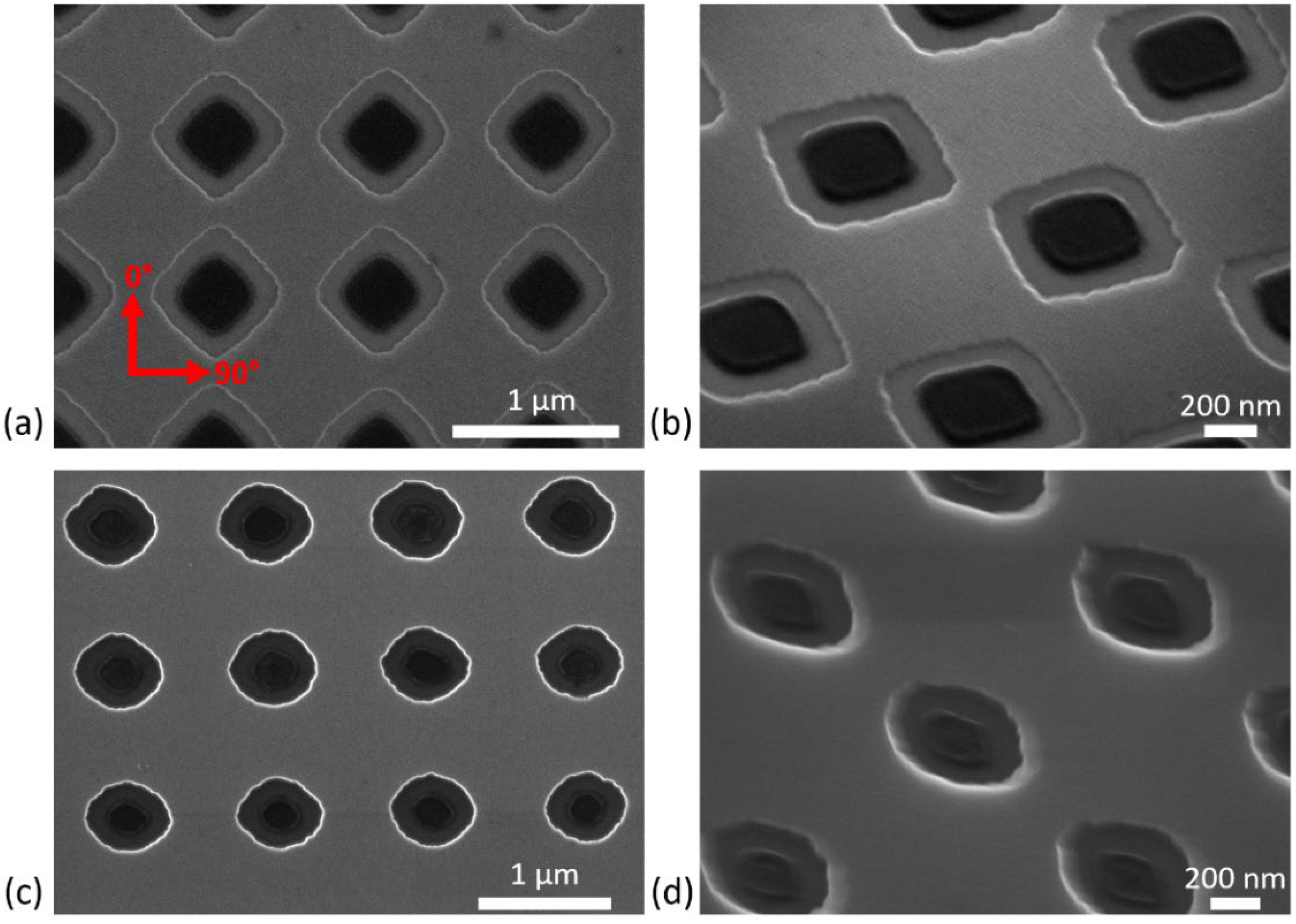
Figure 1. SEM images of the antidot lattices studied, including the 10 nm thick antidot lattices (a,b) and the 50 nm thick antidot lattices (c,d). Panels (b,d) are tilted SEM images taken at an angle of 30 degrees with respect to the electron beam direction. The red arrows denote the directions along which the hysteresis loops are measured. The direction of the applied field during growth corresponded to 0°.
Magnetochemistry 08 00055 g001
Figure 2. Room temperature hysteresis loops recorded from (a) 10 nm thick and (b) 50 nm thick permalloy thin films grown using electron-beam evaporation with an applied field of 500 Oe. The angles indicated in the legend correspond to the field direction with respect to the applied field during growth. Insets are zoomed regions around HC for each plot.
Magnetochemistry 08 00055 g002
Figure 3. Room temperature hysteresis loops recorded from (a) 10 nm thick and (b) 50 nm thick permalloy antidot lattices grown by electron-beam evaporation with an applied field of 500 Oe parallel to one lattice axis (0°). Insets are zoomed regions around Hc for each plot.
Magnetochemistry 08 00055 g003
Figure 4. Hysteresis loops simulated on (a) 10 nm and (b) 50 nm thick antidot lattices with similar antidot shapes to those observed in their corresponding nanofabricated samples presented in Figure 1. The hysteresis loops presented were simulated with fields applied at similar angles to those presented in Figure 2. The insets correspond to relevant representative magnetization states obtained from the micromagnetic simulations in specific fields of the 0° hysteresis loops. The color scale depicting the directions of the magnetization vectors presented in the insets is shown in the bottom central part of the figure.
Magnetochemistry 08 00055 g004
Publisher’s Note: MDPI stays neutral with regard to jurisdictional claims in published maps and institutional affiliations.