
Mechanical Study of Various Pedicle Screw Systems including Percutaneous Pedicle Screw in Trauma Treatment

 ,
,  and
and
Abstract
:1. Introduction
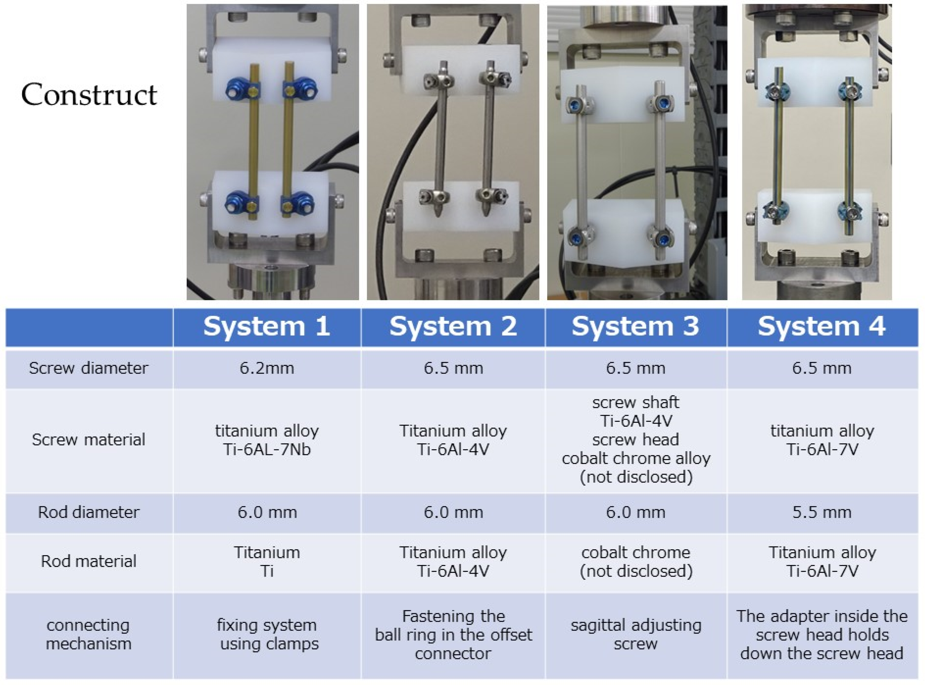
2. Methods
- System 1—open system for trauma, screw diameter: 6.2 mm, screw material: Ti-6Al-7Nb, rod diameter: 6.0 mm, rod material: titanium (Ti), connection mechanism: fixing system using clamps.
- System 2—PPS system for trauma, screw diameter: 6.5 mm, screw material: Ti-6Al-4V, rod diameter: 6.0 mm, rod material: Ti-6Al-4V, connecting mechanism: fastening using a ball ring in the offset connector.
- System 3—PPS system for trauma, screw diameter: 6.5 mm, screw material: screw shaft of Ti-6Al-4V, screw head of cobalt–chrome alloy (not disclosed), rod diameter: 6.0 mm, rod material: cobalt–chromium alloy (not disclosed), connecting mechanism: using a sagittal adjusting screw.
- System 4—general PPS system, screw diameter: 6.5 mm, rod material: Ti-6Al-4V, rod diameter: 5.5 mm, rod material: Ti-6Al-4V, connecting mechanism: a mechanism where the adapter inside the screw head holds down the screw head.
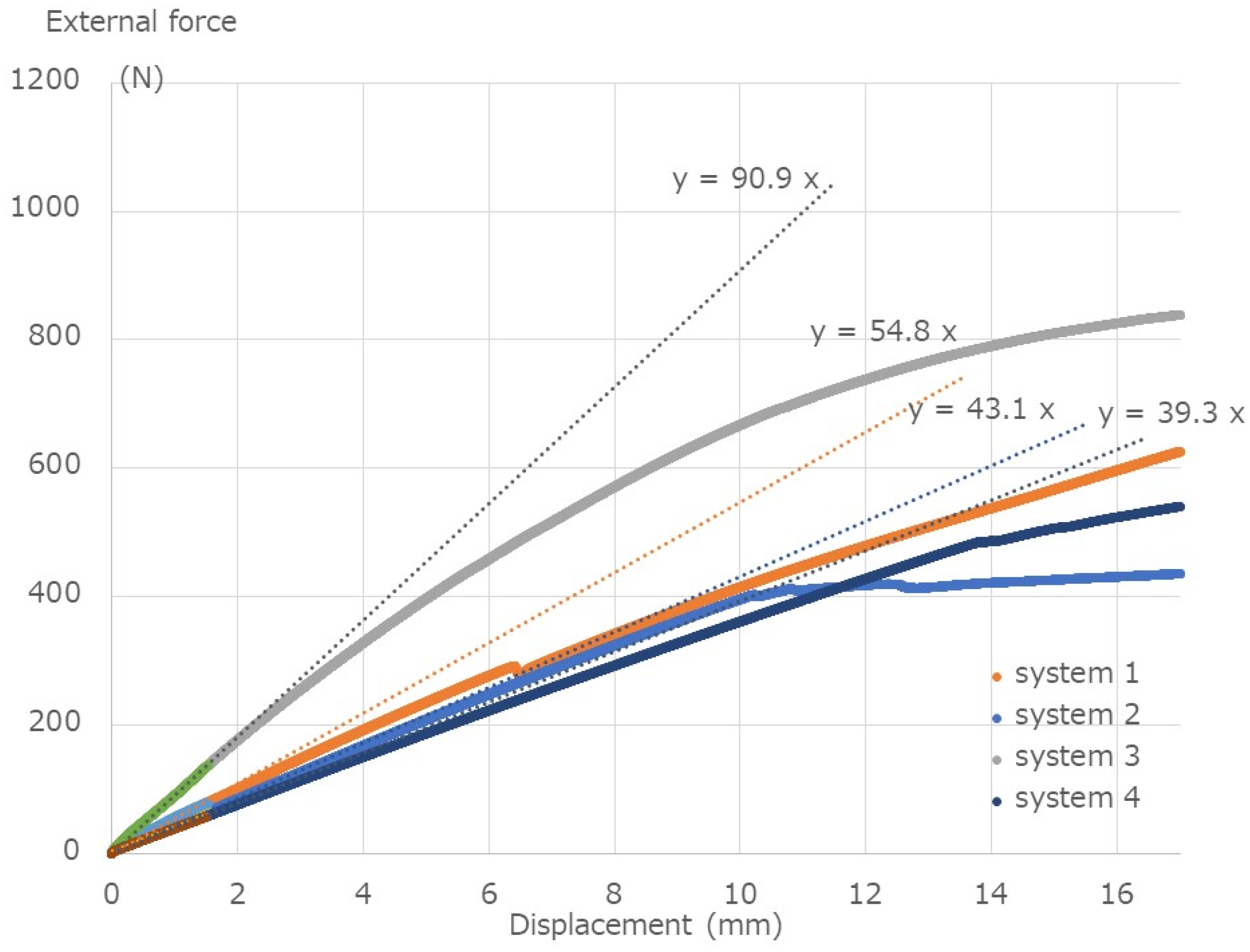
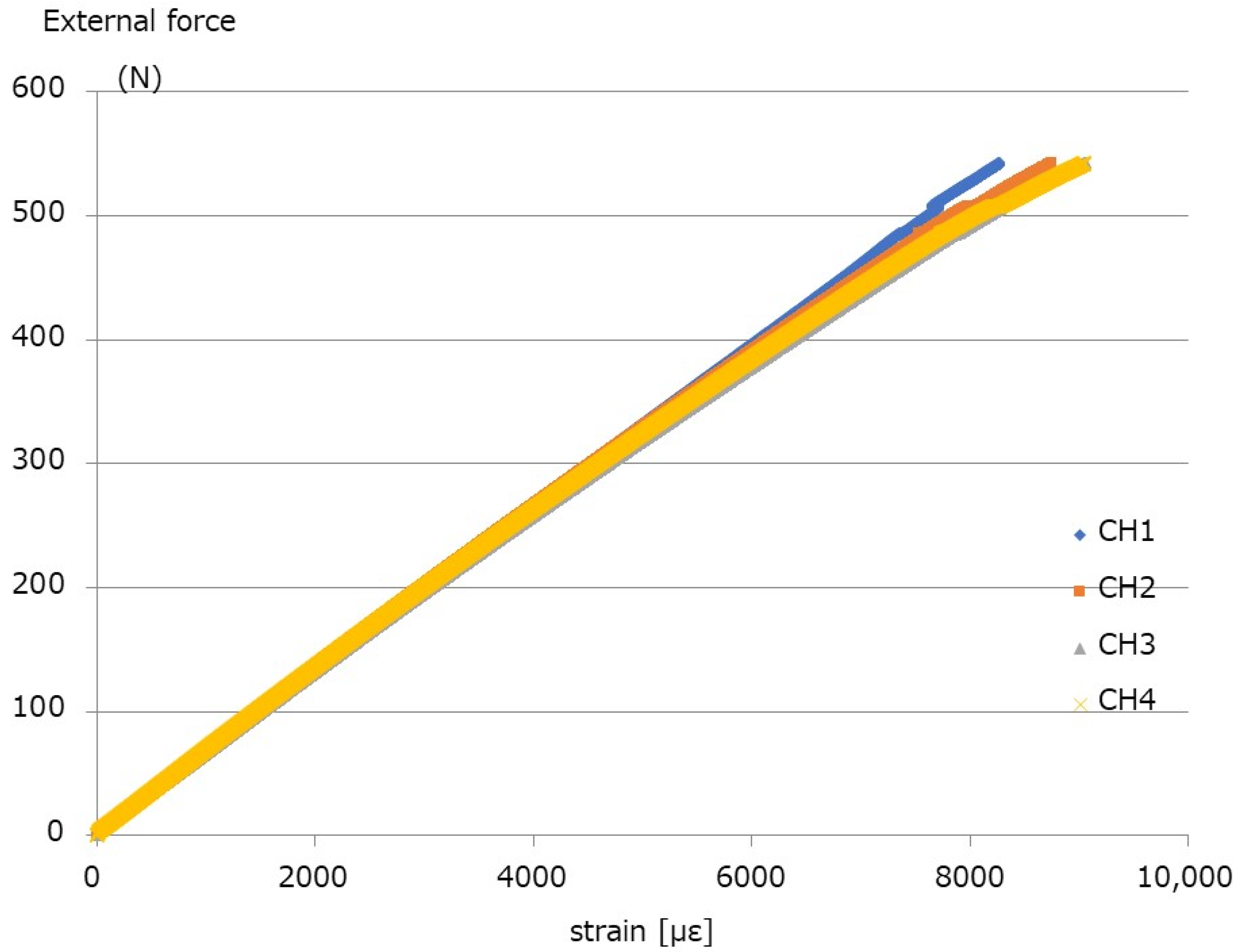
2.1. Break Test
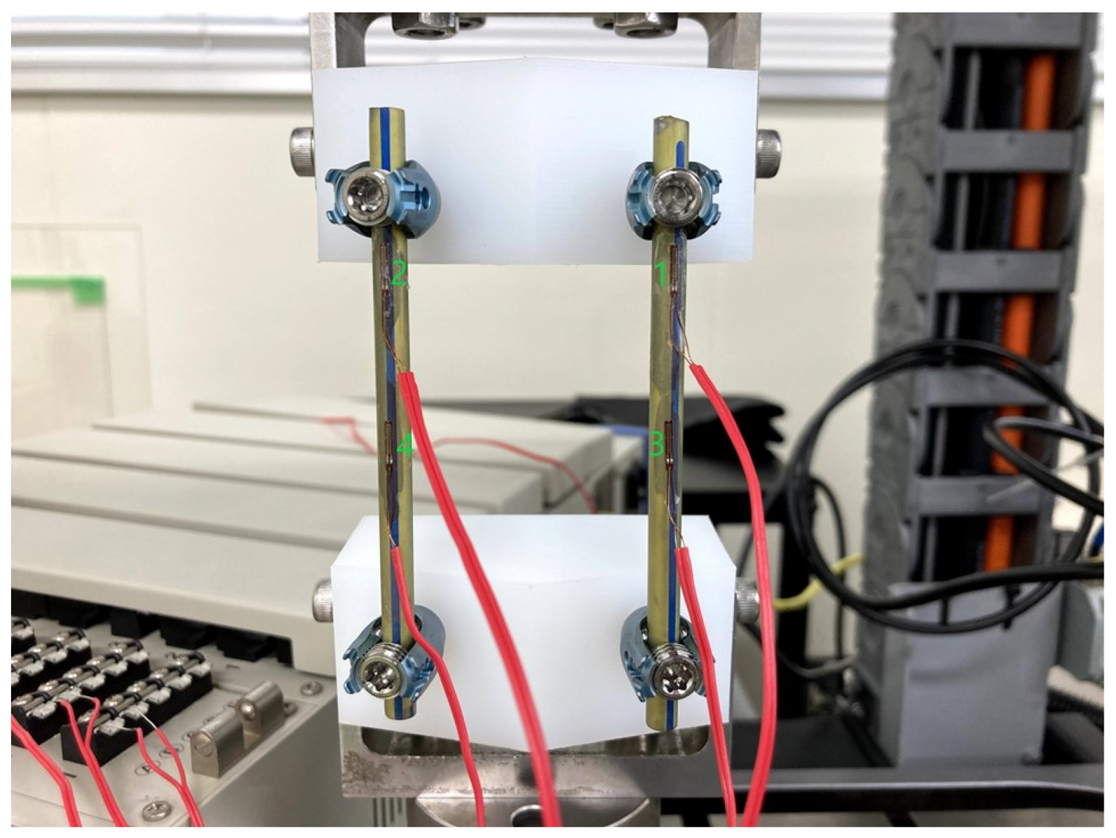
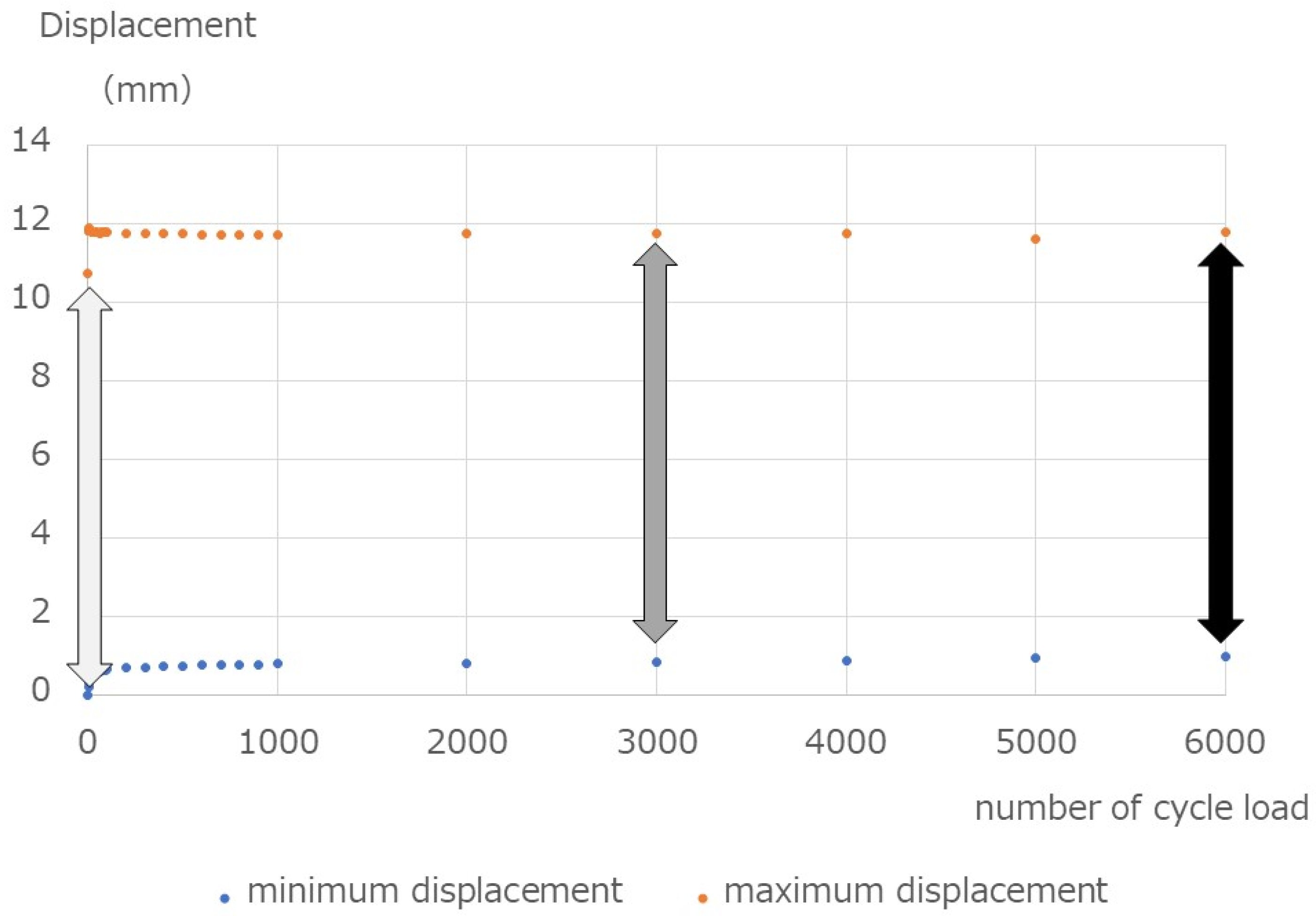
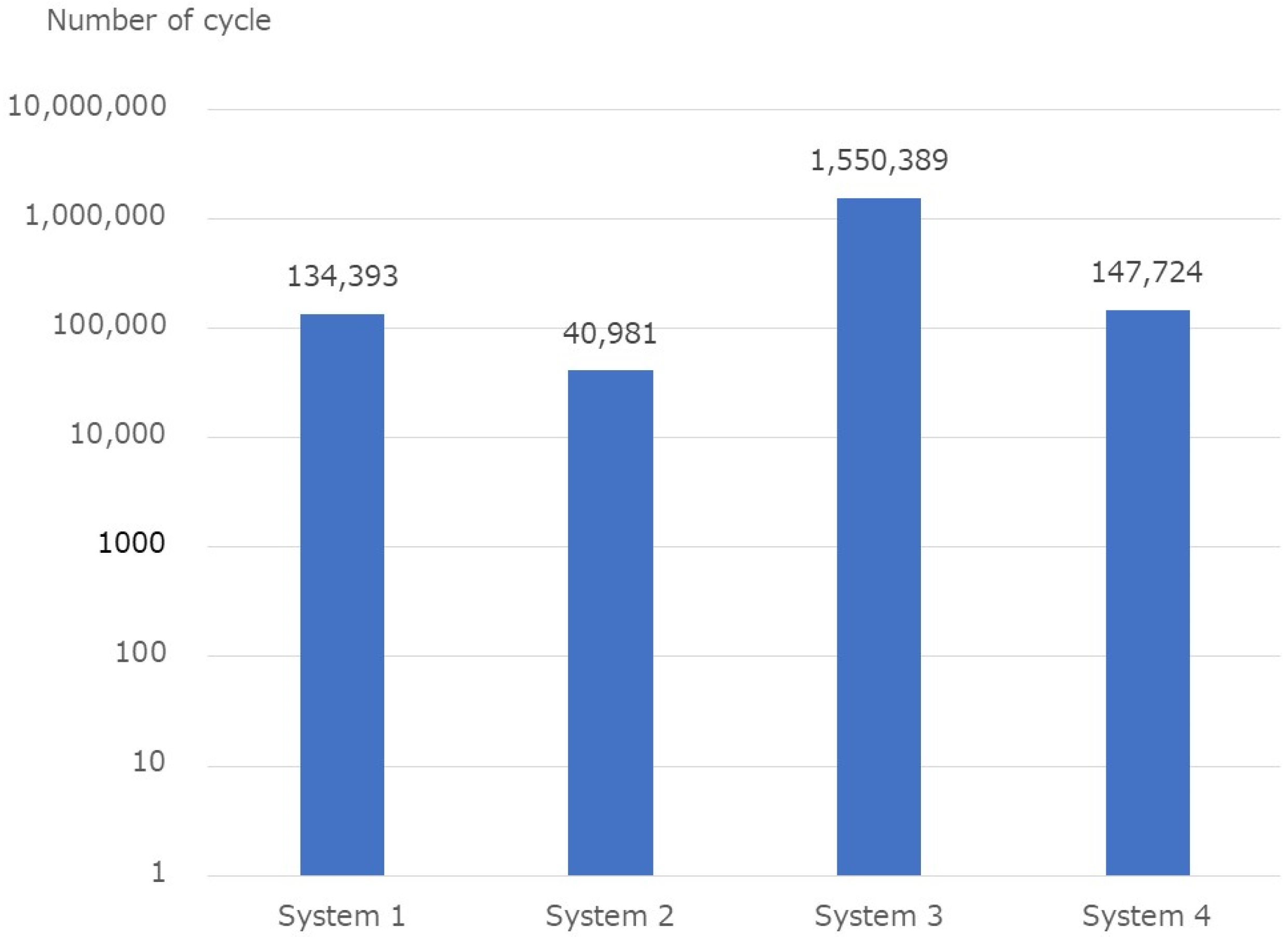
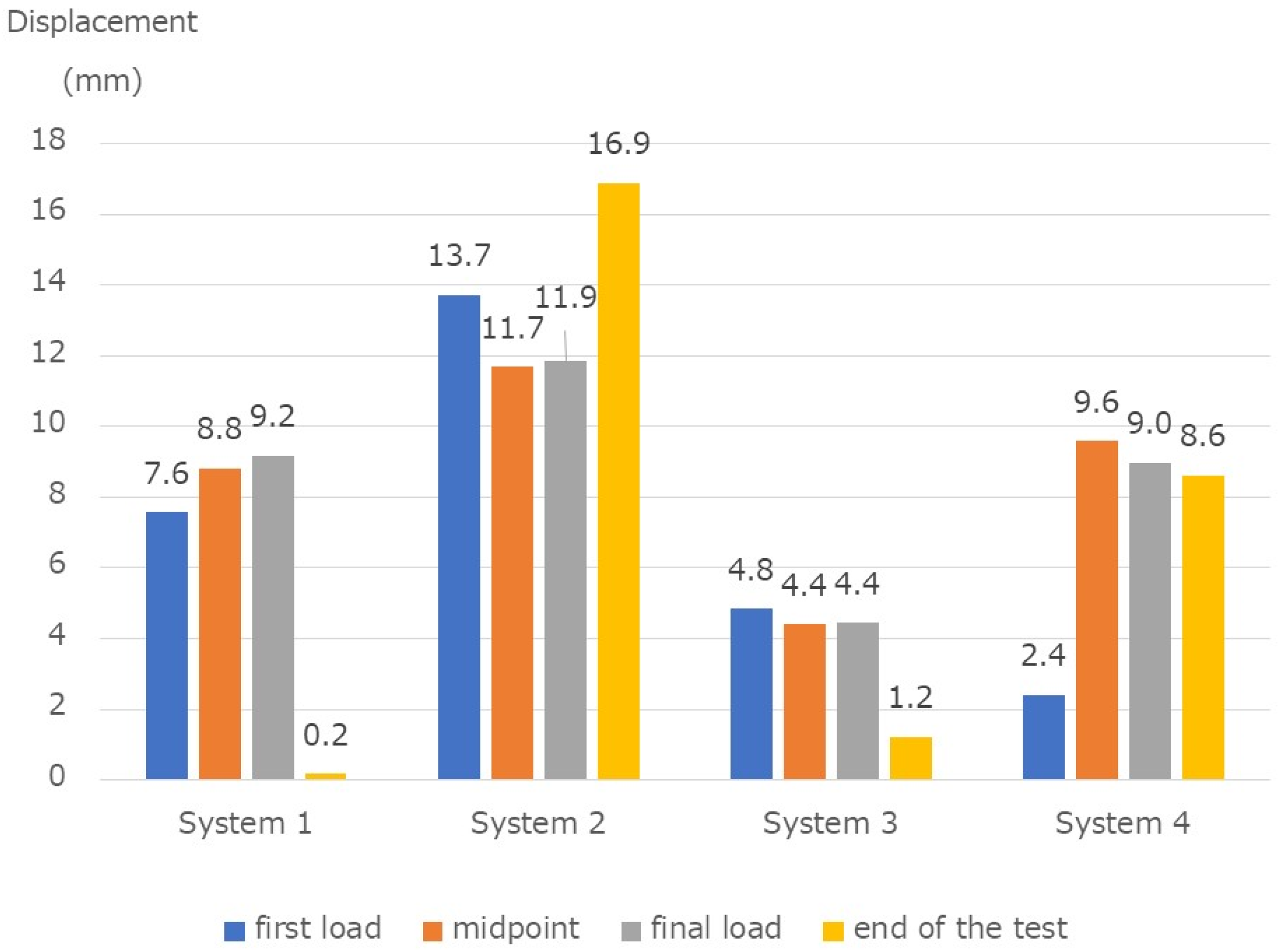
2.2. Fatigue Test
3. Results
4. Discussion
5. Conclusions
Author Contributions
Funding
Data Availability Statement
Acknowledgments
Conflicts of Interest
References
- Foley, K.T.; Holly, L.T.; Schwender, J.D. Minimally invasive lumbar fusion. Spine 2003, 28, S26–S35. [Google Scholar] [CrossRef] [PubMed]
- Park, P.; Wang, M.Y.; Lafage, V.; Nguyen, S.; Ziewacz, J.; Okonkwo, D.O.; Uribe, J.S.; Eastlack, R.K.; Anand, N.; Haque, R.; et al. Comparison of two minimally invasive surgery strategies to treat adult spinal deformity. J. Neurosurg. Spine 2015, 22, 374–380. [Google Scholar] [CrossRef] [PubMed] [Green Version]
- Dhall, S.S.; Wang, M.Y.; Mummaneni, P.V. Clinical and radiographic comparison of mini-open transforaminal lumbar interbody fusion with open transforaminal lumbar interbody fusion in 42 patients with long-term follow-up. J. Neurosurg. Spine 2008, 9, 560–565. [Google Scholar] [CrossRef] [PubMed]
- Isaacs, R.E.; Podichetty, V.K.; Santiago, P.; Sandhu, F.; Spears, J.; Kelly, K.; Rice, L.; Fessler, R.G. Minimally invasive microendoscopy-assisted transforaminal lumbar interbody fusion with instrumentation. J. Neurosurg. Spine 2005, 3, 98–105. [Google Scholar] [CrossRef] [PubMed]
- Lee, K.H.; Yue, W.M.; Yeo, W.; Soeharno, H.; Tan, S.B. Clinical and radiological outcomes of open versus minimally invasive transforaminal lumbar interbody fusion. Eur. Spine J. 2012, 21, 2265–2270. [Google Scholar] [CrossRef] [PubMed]
- Ni, W.-F.; Huang, Y.-X.; Chi, Y.-L.; Xu, H.-Z.; Lin, Y.; Wang, X.-Y.; Huang, Q.-S.; Mao, F.-M. Percutaneous pedicle screw fixation for neurologic intact thoracolumbar burst fractures. J. Spinal Disord. Technol. 2010, 23, 530–537. [Google Scholar] [CrossRef] [PubMed]
- Schmidt, O.I.; Strasser, S.; Kaufmann, V.; Strasser, E.; Gahr, R.H. Role of early minimal-invasive spine fixation in acute thoracic and lumbar spine trauma. Indian J. Orthop. 2007, 41, 374–380. [Google Scholar] [CrossRef] [PubMed]
- Hubbe, U.; Kogias, E.; Vougioukas, V.I. Image guided percutaneous trans-pedicular screw fixation of the thoracic spine. A clinical evaluation. Acta Neurochir 2009, 151, 545–549. [Google Scholar] [CrossRef] [PubMed]
- Yang, W.E.; Ng, Z.X.; Koh, K.M.; Low, S.W.; Lwin, S.; Choy, K.S.; Seet, E.; Yeo, T.T. Percutaneous pedicle screw fixation for thoracolumbar burst fracture: A Singapore experience. Singap. Med. J. 2012, 53, 577–581. [Google Scholar]
- Weiner, B.K.; Walker, M.; Brower, R.S.; McCulloch, J.A. Microdecompression for lumbar spinal canal stenosis. Spine 1999, 24, 2268–2272. [Google Scholar] [CrossRef] [PubMed]
- Kim, C.H.; Chung, C.K.; Sohn, S.; Lee, S.; Park, S.B. Less invasive palliative surgery for spinal metastases. J. Surg. Oncol. 2013, 108, 499–503. [Google Scholar] [CrossRef] [PubMed]
- ASTM F1717-13; Standard Test Methods for Spinal Implant Constructs in a Vertebrectomy Model. ASTM International: West Conshohocken, PA, USA, 2013.
- Niinomi, M. Metals for Biomedical Devices; Woodhead Publishing: Sawston, UK, 2010; pp. 122–156. [Google Scholar]
- Palmisani, M.; Gasbarrini, A.; Brodano, G.B.; De Iure, F.; Cappuccio, M.; Boriani, L.; Amendola, L. Minimally invasive percutaneous fixation in the treatment of thoracic and lumbar spine fractures. Eur. Spine J. 2009, 18 (Suppl. S1), S71–S74. [Google Scholar] [CrossRef] [PubMed] [Green Version]
- Fogel, G.R.; Reitman, C.A.; Liu, W.; Esses, S.I. Physical characteristics of polyaxial-headed pedicle screws and biomechanical comparison of load with their failure. Spine 2003, 28, 470–473. [Google Scholar] [CrossRef] [PubMed]
- Stanford, R.E.; Loefler, A.H.; Stanford, P.M.; Walsh, W.R. Multiaxial pedicle screw designs: Static and dynamic mechanical testing. Spine 2004, 29, 367–375. [Google Scholar] [CrossRef] [PubMed]
- Rohlmann, A.; Bergmann, G.; Graichen, F. Loads on an internal spinal fixation device during walking. J. Biomech. 1997, 30, 41–47. [Google Scholar] [CrossRef]
- Noshchenko, A.; Xianfeng, Y.; Armour, G.A.; Baldini, T.; Patel, V.V.; Ayers, R.; Burger, E. Evaluation of spinal instrumentation rod bending characteristics for in-situ contouring. J. Biomed. Mater. Res. B Appl. Biomater. 2011, 98, 192–200. [Google Scholar] [CrossRef] [PubMed]
- Kubosch, D.; Kubosch, E.J.; Gueorguiev, B.; Zderic, I.; Windolf, M.; Izadpanah, K.; Südkamp, N.P.; Strohm, P.C. Biomechanical investigation of a minimally invasive posterior spine stabilization system in comparison to the Universal Spinal System (USS). BMC Musculoskelet Disord. 2016, 17, 134. [Google Scholar] [CrossRef] [PubMed] [Green Version]
- Demura, S.; Murakami, H.; Hayashi, H.; Kato, S.; Yoshioka, K.; Yokogawa, N.; Ishii, T.; Igarashi, T.; Fang, X.; Tsuchiya, H. Influence of rod contouring on rod strength and stiffness in spine surgery. Orthopedics 2015, 38, e520–e523. [Google Scholar] [CrossRef] [PubMed]
- Nguyen, T.Q.; Buckley, J.M.; Ames, C.; Deviren, V. The fatigue life of contoured cobalt chrome posterior spinal fusion rods. Proc. Inst. Mech. Eng. Part H 2011, 225, 194–198. [Google Scholar] [CrossRef] [PubMed]


| System 1 | System 2 | System 3 | System 4 | |
|---|---|---|---|---|
| Yield value (N) | 79.3 | 64.6 | 136.8 | 57.0 |
| Stiffness (N/mm) | 54.8 | 43.1 | 90.9 | 39.3 |
| Failure | − | + | − | − |
| Specimen No. | Number of Cycles | Broken Part | Displacement at First Load (mm) | Displacement at Midpoint (mm) | Displacement at Final Load (mm) | Displacement at the End (mm) | |
|---|---|---|---|---|---|---|---|
| 1 | 35,273 | Screw | 8.6 | 9.5 | 10.6 | −0.6 | |
| System 1 | 2 | 26,935 | Screw | 9.3 | 9.9 | 9.8 | 0.1 |
| 3 | 340,972 | Screw | 4.8 | 7.1 | 7.1 | −0.1 | |
| 4 | 54,781 | Rod | 14.3 | 12.7 | 12.6 | 21.1 | |
| System 2 | 5 | 23,818 | Rod | 13.7 | 12.0 | 12.1 | 14.4 |
| 6 | 44,343 | Screw | 13.1 | 10.4 | 10.9 | 15.2 | |
| 7 | 2,000,000 | - | 4.9 | 4.3 | 4.3 | 1.1 | |
| System 3 | 8 | 651,166 | Screw | 4.9 | 4.6 | 4.7 | 1.2 |
| 9 | 2,000,000 | - | 4.7 | 4.3 | 4.3 | 1.4 | |
| 10 | 161,819 | Rod | 2.3 | 9.5 | 9.7 | 8.0 | |
| System 4 | 11 | 136,557 | Rod | 2.3 | 9.4 | 9.7 | 8.3 |
| 12 | 144,796 | Rod | 2.6 | 9.8 | 7.5 | 9.5 |
Publisher’s Note: MDPI stays neutral with regard to jurisdictional claims in published maps and institutional affiliations. |
© 2022 by the authors. Licensee MDPI, Basel, Switzerland. This article is an open access article distributed under the terms and conditions of the Creative Commons Attribution (CC BY) license (https://creativecommons.org/licenses/by/4.0/).
Share and Cite
Oda, Y.; Takigawa, T.; Ito, Y.; Misawa, H.; Tetsunaga, T.; Uotani, K.; Ozaki, T. Mechanical Study of Various Pedicle Screw Systems including Percutaneous Pedicle Screw in Trauma Treatment. Medicina 2022, 58, 565. https://doi.org/10.3390/medicina58050565
Oda Y, Takigawa T, Ito Y, Misawa H, Tetsunaga T, Uotani K, Ozaki T. Mechanical Study of Various Pedicle Screw Systems including Percutaneous Pedicle Screw in Trauma Treatment. Medicina. 2022; 58(5):565. https://doi.org/10.3390/medicina58050565
Chicago/Turabian StyleOda, Yoshiaki, Tomoyuki Takigawa, Yasuo Ito, Haruo Misawa, Tomoko Tetsunaga, Koji Uotani, and Toshifumi Ozaki. 2022. "Mechanical Study of Various Pedicle Screw Systems including Percutaneous Pedicle Screw in Trauma Treatment" Medicina 58, no. 5: 565. https://doi.org/10.3390/medicina58050565