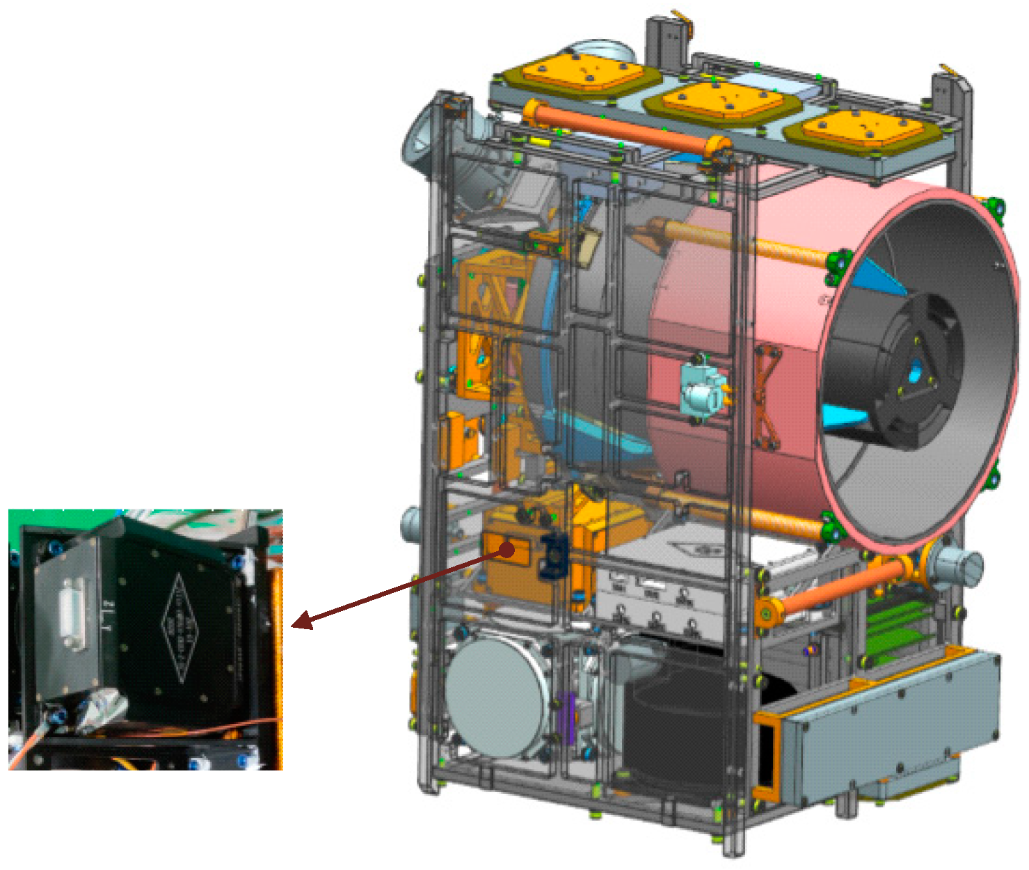
Article

Research on Design, Simulation, and Experiment of Separation Mechanism for Micro-Nano Satellites

1
Changchun Institute of Optics, Fine Mechanics and Physics, Chinese Academy of Sciences, Changchun 130033, China
2
University of Chinese Academy of Sciences, Beijing 100049, China
3
Chang Guang Satellite Technology Co., Ltd., Changchun 130000, China
*
Author to whom correspondence should be addressed.
Appl. Sci. 2022, 12(12), 5997; https://doi.org/10.3390/app12125997
Submission received: 23 April 2022 / Revised: 28 May 2022 / Accepted: 6 June 2022 / Published: 13 June 2022
(This article belongs to the Section Aerospace Science and Engineering)

Abstract

:
The separation mechanism is a critical device that transports and releases satellites during launch and on-orbit. However, as satellites become smaller and more compact, the traditional belt-locking device or pyrotechnic release and separation device cannot meet the micro-nano satellite’s separation requirements. A novel separation mechanism kinematic system was designed, analyzed, and experimentally verified to achieve non-interference and non-pyrotechnic separation of the satellites from the launch vehicle while maintaining the initial separation attitude. First, an overall structural strategy for the kinematics system was proposed based on the MF (product code of the satellite) satellite’s structural properties. The structural characteristics of the separation mechanism were also confirmed by the principle of energy conservation. Then, a finite element model and a dynamic model of the kinematic coupling system between the MF satellite and the separation mechanism during launch and deployment were constructed, along with an analysis of the mechanical characteristics and a kinematic simulation. Finally, the mechanical characteristics and dependability of the separation mechanism were verified using a ground vibration test and a separation test. The prototype test results demonstrate that the separation process is essentially identical to the numerical simulation results and that the MF satellite can be deployed successfully without interference, with the MF satellite’s initial separation attitude fully satisfying the designed technical indexes.

1. Introduction

The development of micro-electro-mechanical and micro-nano technology has caused a reduction in the size of optical, mechanical, electrical, and other equipment. At the end of the twentieth century, there was a boom in research on small satellites, and their application has grown rapidly [1,2,3,4,5,6]. Due to their low cost, modularity, and standardization, micro-nano satellites such as picosatellites are acquiring much more attention in the aerospace field [7,8,9]. Numerous micro-nano satellites working in unison could be used for formation flying, establishing large load platforms, and other tasks in the future [10,11,12,13,14,15,16]. However, unlike large satellites, micro-nano satellites have a limited internal volume, making the high-performance shock and vibration damping systems impractical. Thus, the shock and vibration generated by the separation mechanism for micro-nano satellites should be strictly limited. This circumstance motivates the development of a non-explosive separation mechanism for the release and separation of micro-nano satellites [17,18,19,20,21,22,23,24,25,26].
To launch numerous micro-nano satellites at the same time and release them according to requirements, a great deal of research has been conducted and some remarkable achievements have been made by many countries regarding the separation mechanism used for carrying and releasing satellites. The P-POD (Poly Picosatellite Orbital Deployer) was developed by the California Institute of Technology and Stanford University. Three generations of P-POD have been developed so far: P-PODMKI, P-POD-MKII, and P-POD-MKIII [27,28]. The XPOD family is a custom-made nanosatellite separation system designed and built at the Space Flight Laboratory of the University of Toronto, UTIAS. Its purpose is to secure the satellite during the extreme conditions of the launch environment. In addition, it serves as the interface between the satellite and the launch vehicle, and it deploys the satellite once it reaches the desired orbit [29]. The J-SSOD (JEM Small Satellite Orbital Deployer) was developed by the Japan Space Agency. This deployer could carry three standard picosatellites and release all three picosatellites at once via springs [30]. The Space Research Centre of the Polish Academy of Sciences together with Astronika company have developed an Orbital Deployer called DRAGON for ejection of the Polish scientific nanosatellite BRITE-PL Heweliusz. The device has three unique mechanisms including an adopted and scaled lock and release mechanism from the ESA Rosetta mission MUPUS instrument [31]. The MASCOT separation mechanism was developed by the German Aerospace Center. The mechanism was compared with other existing deployment systems and its performance was verified with two independent analysis methods using actual flight data taken during the ultimate flight activation event, which initiated the successful delivery and surface operation of the MASCOT asteroid lander [21]. To satisfy additional requirements for picosatellites, those deployers named SPL (Single Picosatellite Launcher) [32,33,34], RAFT (one picosatellite’s name), and GNB (Generic Nanosatellite Bus) were developed by Germany, the USA, and Canada, respectively [31,33,35].
In summary, the separation mechanism serves as a vital interface between the satellite and the launch vehicle. However, it should not jeopardize the success of the primary spacecraft or launch vehicle. Numerous modern nanosatellite deployers now support nanosatellites of varying sizes, multiples, or swarms [33]. On the other hand, these separation mechanisms are typically used to launch 1U-3U experimental CubeSats. The satellites have a simple structure, a single function, and only a few protrusions on their surface, and the mass ratio of the satellite to the separation mechanism is extremely high, usually around 1, which increases the launch cost. As a result, it is critical to develop a separation mechanism with a low mass ratio and a large enough volume to accommodate satellites with complex functions and numerous protrusions on their surface. In this study, we present and validate the design of the separation mechanism for the MF satellite through FEAs and prototype tests. The separation mechanism’s design serves as a model for a variety of small and micro-nano satellite separation mechanisms. Especially, the separation mechanism has two distinct advantages over the conventional mechanism. First, the separation mechanism proposed in this paper is low-cost, lightweight, modular, and adaptable. It makes use of an integrated guide rail and a main bearing structure, which is simple to process and ensures the accuracy of the guide rail. The separation mechanism weighs less than 6 kg and is capable of supporting a satellite weighing up to 20 kg. Second, the separation mechanism is non-explosive and is capable of being reused multiple times on the ground.
In this paper, we analyze the separation mechanism’s task requirements and develop the separation mechanism’s overall scheme and motion system in accordance with the task requirements. Then, to verify the design’s rationality and reliability, the finite element model and dynamic model of the combination of the satellite and the separation mechanism were established. Finally, the rationality and reliability of the separation mechanism design were verified by comparing the simulation results with the prototype test results.

2. Mission Analysis

2.1. Satellite Description

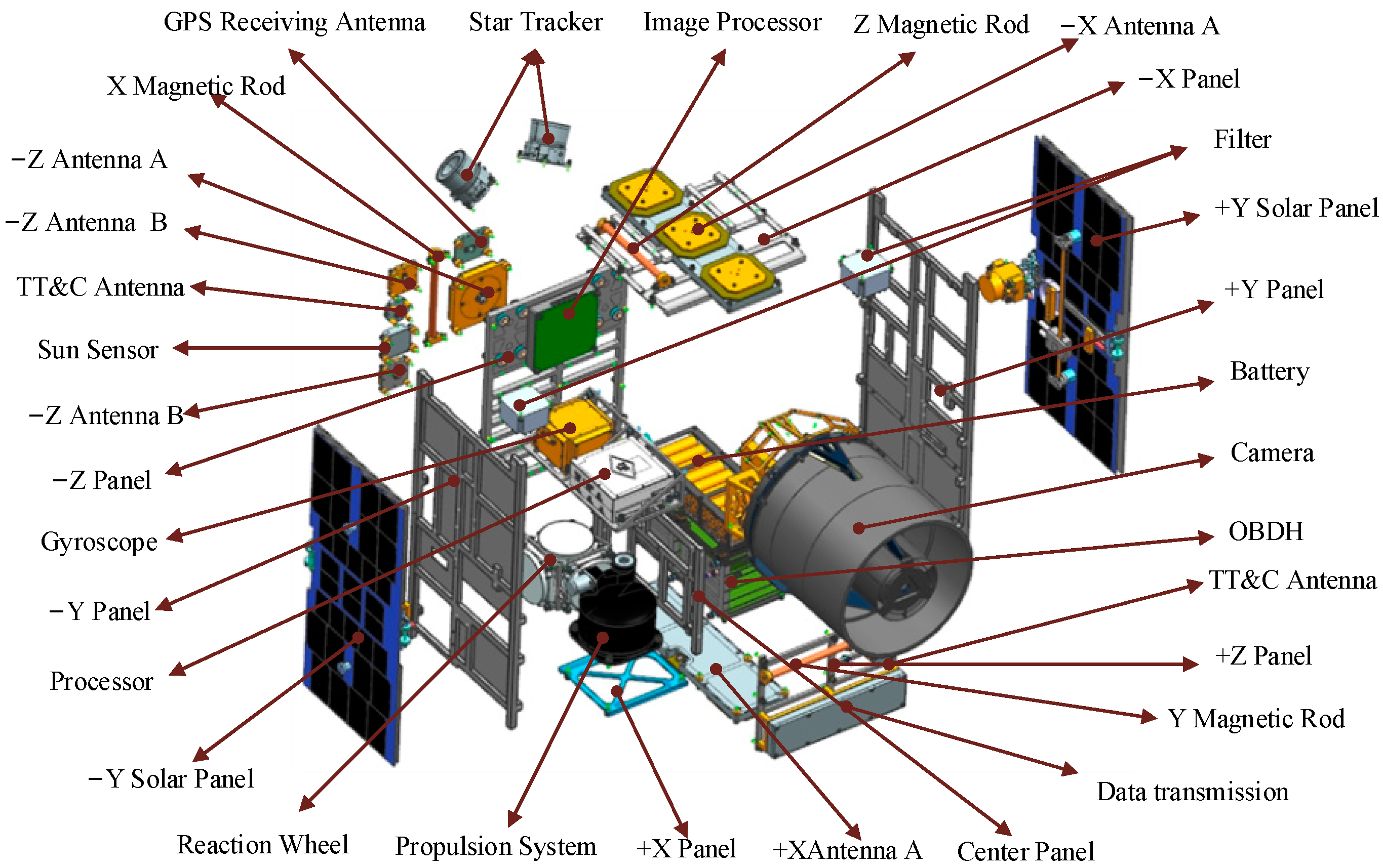
As shown in Figure 1, MF is a micro-optical satellite designed based on the principles of “modularity, standardization, lightweight, low cost, scalability, flexibility, and high resolution”. The designed orbit of the satellite is a 500 km sun-synchronous orbit. The resolution of remote sensing is better than 1.35 m, making it suitable for earth observation, new technology verification, scientific exploration, and other fields. The entire satellite structure system is supported by a frame made of the lightweight aluminum alloy 2A12, and the MF satellite weighs about 20 kg. The satellite is equipped with an expanded solar panel on the ±Y direction. On the ±Z side, there is a camera and various antennas. On the ±X side, there is a propulsion system and antennas arrangement. As shown in Figure 2, the satellite’s cabin contains an image processor, a gyroscope, a battery, and a reaction wheel, among other components. Outside the satellite’s cabin are star trackers, various types of antennas, and other devices. As can be seen, the satellite’s entire structure is compact.

2.2. Separation Mechanism Design Requirements

The separation mechanism’s primary purpose is to obtain approval from launch vehicle service providers by ensuring the launch vehicles’ and other satellites’ safety. The separation mechanism must meet all requirements imposed by launch vehicle providers and other satellite producers.
First, in the event of the MF satellite’s catastrophic failure, the separation mechanism must protect the launch vehicle and other satellites from the mechanical, electrical, or electromagnetic interference caused by the MF satellite. Second, the MF satellite must be released from the separation mechanism with as little spin as possible and with the least chance of colliding with a launch vehicle or other satellites. Finally, the separation mechanism must be adaptable to a wide variety of launch vehicles and satellites with minimal modification while maintaining a low weight [36].
Table 1 summarizes the design indexes for the separation mechanism that must be satisfied based on the mission requirements and satellite attributes. Each of the separation mechanism’s dimensions, mass, separation velocity, separation angular velocity, and protrusion storage capacity must be taken into account when making the design of the separation mechanism.

3. Design of the Separation Mechanism

3.1. Overall Design

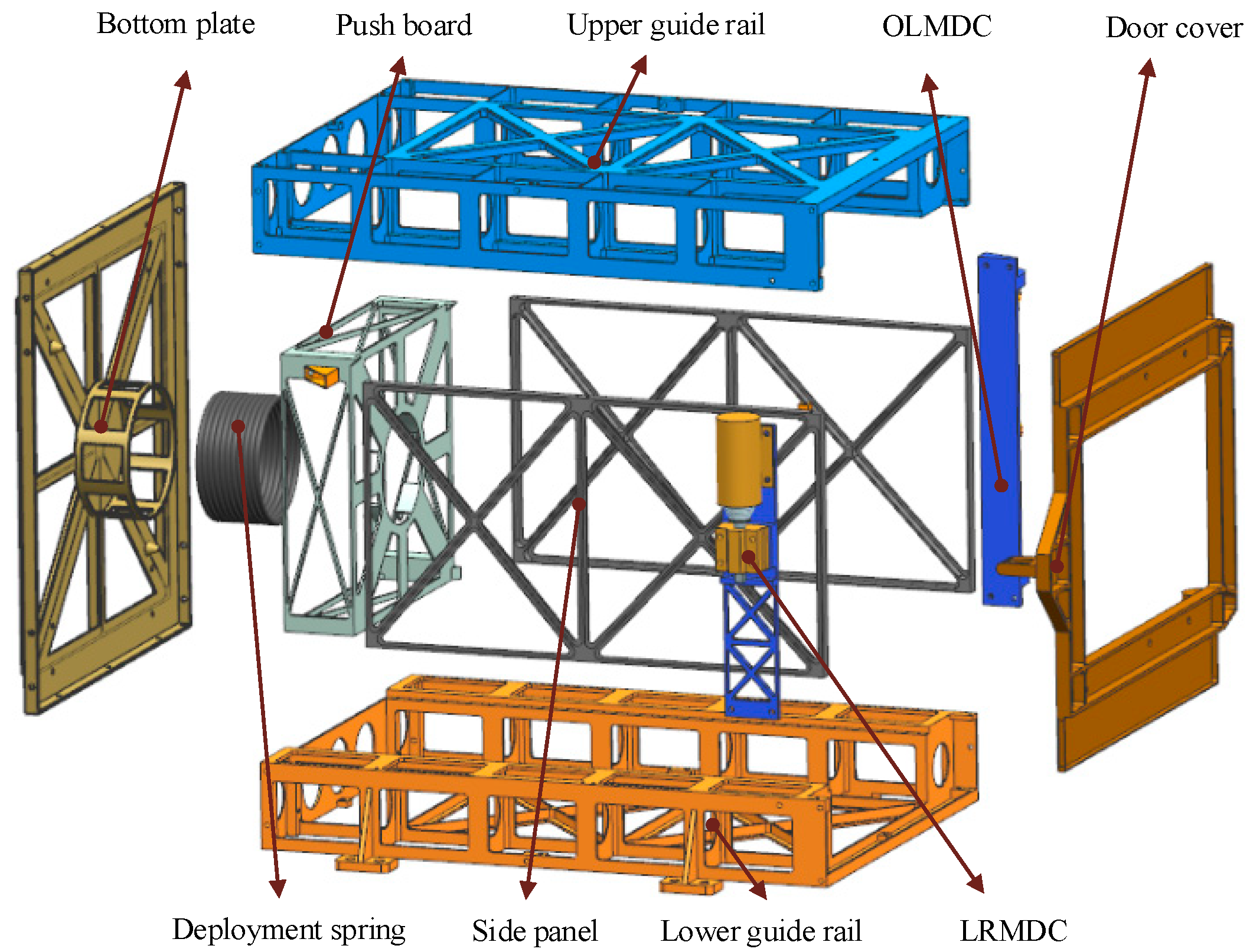
The MF satellite’s separation mechanism is tube-shaped, and the entire structure is box-symmetrical. As illustrated in Figure 3, the separation mechanism is mainly composed of the bottom plate, deployment spring, push board, upper guide rail, lower guide rail, side panel, door cover, opening and locking module for the door cover (OLMDC), and locking and releasing module for the door cover (LRMDC). The bottom plate, upper guide rail, lower guide rail, side panel, and door cover form the separation mechanism’s primary load-bearing structure. The ejection system is composed of a deployment spring and a push board. Through the use of an electromagnet, the LRMDC mechanism achieves power-on unlocking and power-off locking. The LRMDC mechanism is non-explosive, has no impact, and can be reused on the ground many times. The separation mechanism’s primary load-bearing structure is made of aluminum alloy 2A12 due to its high strength, low density, low cost, and ease of manufacture. The upper and lower guide rails are integrated with the strengthening rib, which is simple to process and assemble and helps maintain the guide rails’ parallelism. The guide rails are hard anodized to prevent cold welding between the satellite’s guide rails and to provide a smooth surface for the MF satellite’s deployment. Due to optimization of the design, the separation mechanism weighs only 5.8 kg. The mass ratio of the satellite to the separation mechanism is only 0.29, significantly less than the mass ratio of the conventional separation mechanism, which significantly reduces launch costs.
As illustrated in Figure 4, the outer envelope of the separation mechanism is 343.5 mm × 470 mm × 516.3 mm in the launch state and 343.5 mm × 675 mm × 945 mm in the on-orbit state. Above the guide rails on each side, an additional 50 mm of space is available to accommodate solar panels, a camera hood, and antennas. The length of the guide rail can be adjusted via the satellite’s guide rail. The MF satellite is inserted into the separation mechanism along the guide rail. The rotational hinge joint in the OLMDC can be used to close and open the door cover. The satellite is in contact with the wedge compression points and the four guide rails of the separation mechanism, which restrict the satellite’s vertical movement. The door cover and push board act as horizontal restrictions on the satellite. Eight screws secure the separation mechanism to the carrier launch vehicle. When the MF satellite reaches orbit, the separation mechanism detects the separation signal, the LRMDC releases the door cover, and the OLMDC opens the door cover. Under the action of the deployment spring, the MF satellite will slide out along the guide rail of the separation mechanism. When the door is opened to a certain angle, it is locked in place by the spring positioning pin to prevent it from bouncing back and interfering with the MF satellite in the event of a collision.

3.2. Mechanism Design

Solar panels are mounted on the MF satellite’s ±Y sides, and the optical camera hood protrudes from the satellite’s surface. Interference collisions between the satellite and the separation mechanism must be avoided during the separation process to avoid damage to the solar panel or the camera. Therefore, a detailed analysis and calculation of the separation mechanism’s motion system are required. The motion system is primarily composed of two components. The ejection system of the satellite comes first, followed by the OLMDC. The following is a detailed design for the two mechanisms mentioned previously.
  • Ejection system
The deployment spring is the most critical component of the ejection system (a cylindrical compression spring). The deployment spring’s primary function is to release the energy storage once the satellite is on-orbit, allowing the satellite to separate from the launch vehicle. Without considering the elastic damping of the spring and the friction between the MF satellite and the separation mechanism, the relationship is as follows:
1 2 k x max 2 = 1 2 M v 2
where
  • k—stiffness coefficient of the deployment spring;
  • x max —maximum displacement of the deployment spring;
  • M —mass of the MF satellite;
  • v —initial ejecting velocity of the MF satellite.
The deployment spring’s maximum displacement is determined by the length of the separation mechanism’s guide rail, the mass of the MF satellite is constant, and the MF satellite’s initial ejecting velocity is determined by the overall index. To ensure satellite separation reliability in this paper, the spring’s maximum displacement is 420 mm, the MF satellite’s initial ejecting velocity is 0.5 m/s–2 m/s, and the satellite weighs 20 kg. According to Formula (1), the range of the deployment spring’s stiffness coefficient k is 28.3 N/m–453.5 N/m.
The deployment spring’s mean diameter and slenderness ratio should not be too small to maintain the push board’s stability; otherwise, the deployment spring’s axial load will cause lateral bending, resulting in the push board losing stability. The deployment spring’s slenderness ratio must satisfy Formula (2) for the spring to be stable.
b = H 0 D 5.3
where
  • H0—free height of the deployment spring;
  • D—mean diameter of the deployment spring.
Given the spring’s maximum displacement of 420 mm and its free height H0 of approximately 470 mm, the spring’s mean diameter can be calculated to be greater than 88.7 mm using Formula (2). We initially chose a mean diameter of 100 mm for the deployment spring in this paper. At the moment, the deployment spring’s stiffness coefficient, mean diameter, and maximum displacement are known, and the remaining parameters can be calculated using Formula (3). The spring is made of 1Cr18Ni9, which has a shear modulus of 71 GPa. Based on the calculation, a variety of spring parameter groups can be chosen.
k = G d 4 8 n D 3
where
  • G—shear modulus of the deployment spring material;
  • D —mean diameter of the deployment spring;
  • n —active coil number of the deployment spring;
  • d —wire diameter of the deployment spring.
  • OLMDC
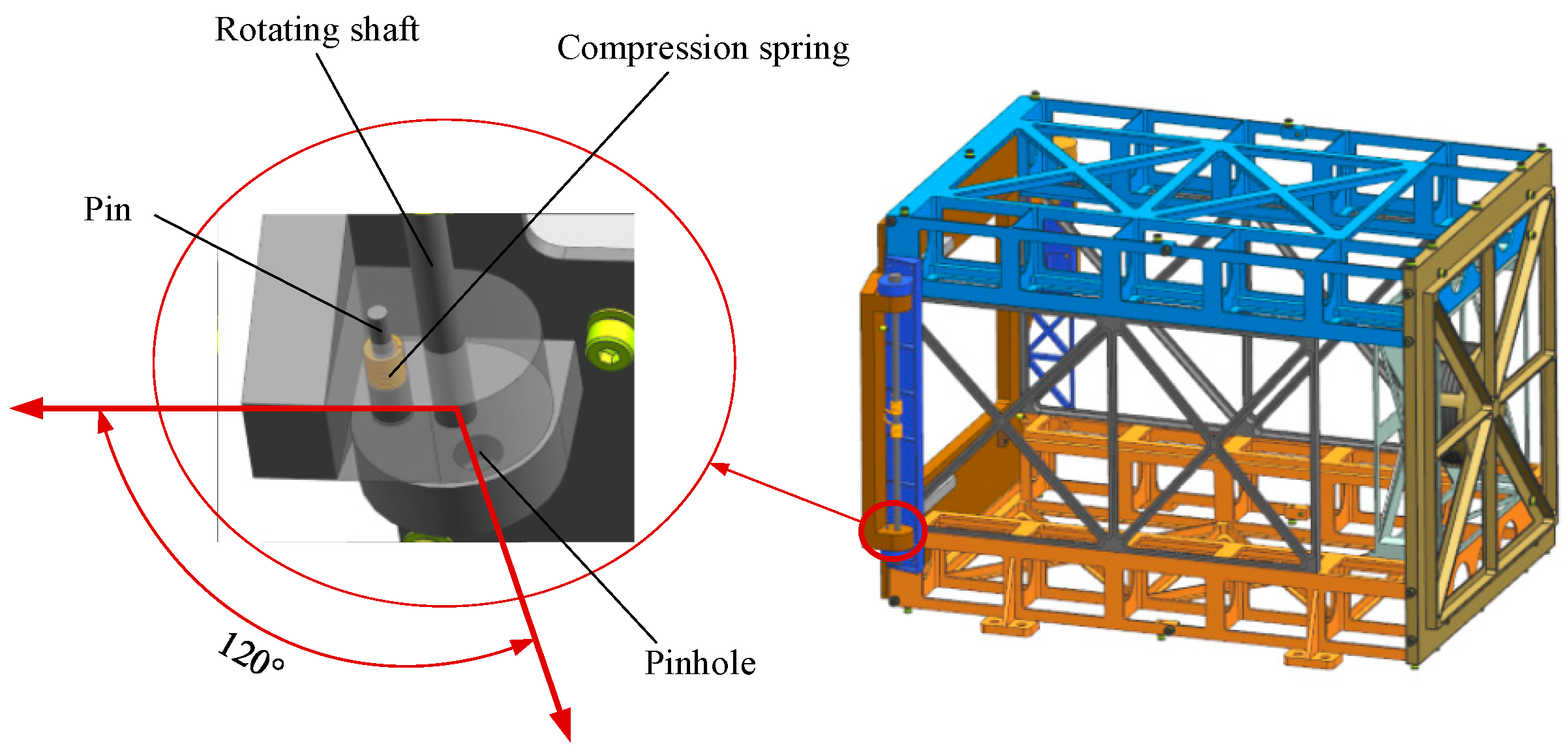
If the door is opened unconstrained, it will collide with the separation mechanism’s side panel and bounce, obstructing the MF satellite’s ejection process and jeopardizing its safety and normal separation. As illustrated in Figure 5, a torsion spring is added to the rotating shaft of the door cover to increase the opening velocity and prevent the door from rebounding. The OLMDC employs a spring positioning pin structure, as illustrated in Figure 6. After the door cover has been extended to a specified angle, the spring positioning pin structure is used to lock it.
Set the matching gap between the pin and the pinhole to ε0, the door cover’s rotating angular velocity when it rotates to the locking position to w0, the distance between the locking hole and the door cover’s rotating shaft to h0, the weight of the positioning pin to m0, the compression spring’s stiffness to k0, the spring’s deformation to d0, and the pin’s locking stroke to δ. When the time required to rotate the door cover ε0/h0 degrees exceeds the time required to lock the compression spring, the door cover can be successfully locked. The following is advisable according to the dynamic principle:
ε 0 h 0 ω 0 > m 0 k 0 arccos d 0 δ d 0
Formula (4) can be used to determine the elastic coefficient selection range of a compression spring. Appropriate positioning pin spring parameters can be determined by combining the shape and size of the positioning pin and pinhole.

4. Analysis

4.1. Model Description

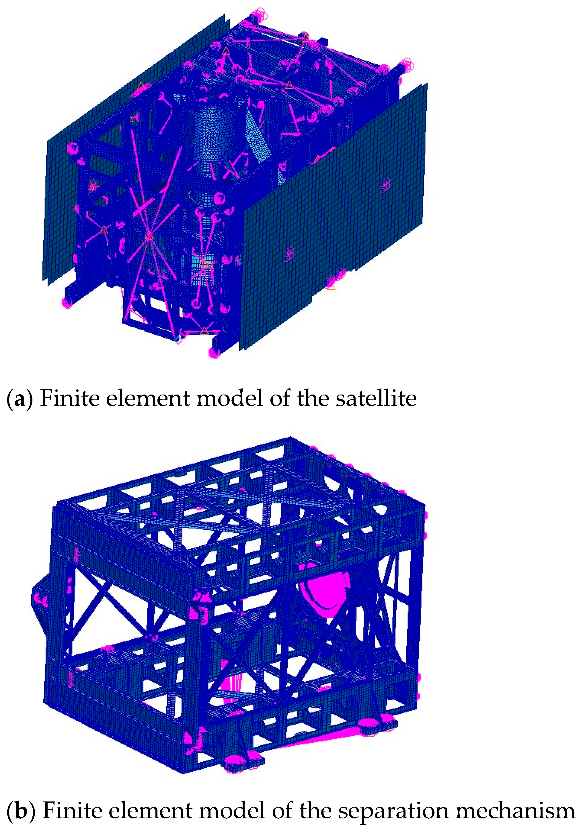
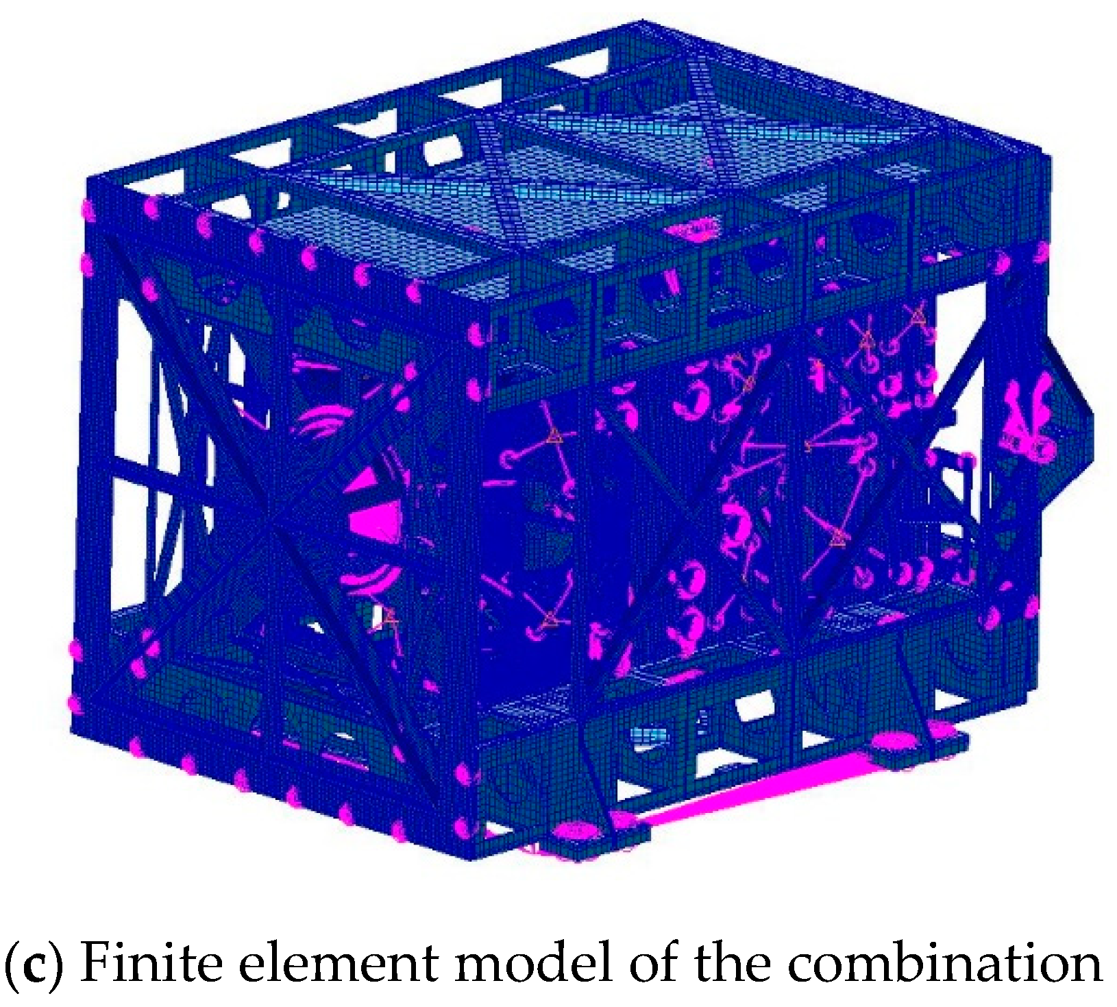
Comprehensive analytical models necessitate a large amount of computational power and a lengthy analysis time. These parameters can be simplified by omitting superfluous information and components that have no effect on physical phenomena. Neglectable components such as connectors, chamfers, and filets were omitted from the structural analytical model. The equipment mounting plate and separation mechanism use solid elements in finite element modeling. The solar panels use a shell unit, and node coupling connects the device mounting plate to it. The solar panels are rigidly coupled to the equipment mounting plate using MPC; each device on the mounting plate uses mass point simulation and is rigidly connected to the mounting point on the plate via MPC. According to the current scenario, contact boundary conditions between the satellite and the separation mechanism’s guide rail are set. The analytical model for the separation mechanism and the MF satellite considered in this study was shown in Figure 7. The elements and nodes had a total of 661,028 and 895,933, respectively.

4.2. Quasi-Static Acceleration Analysis

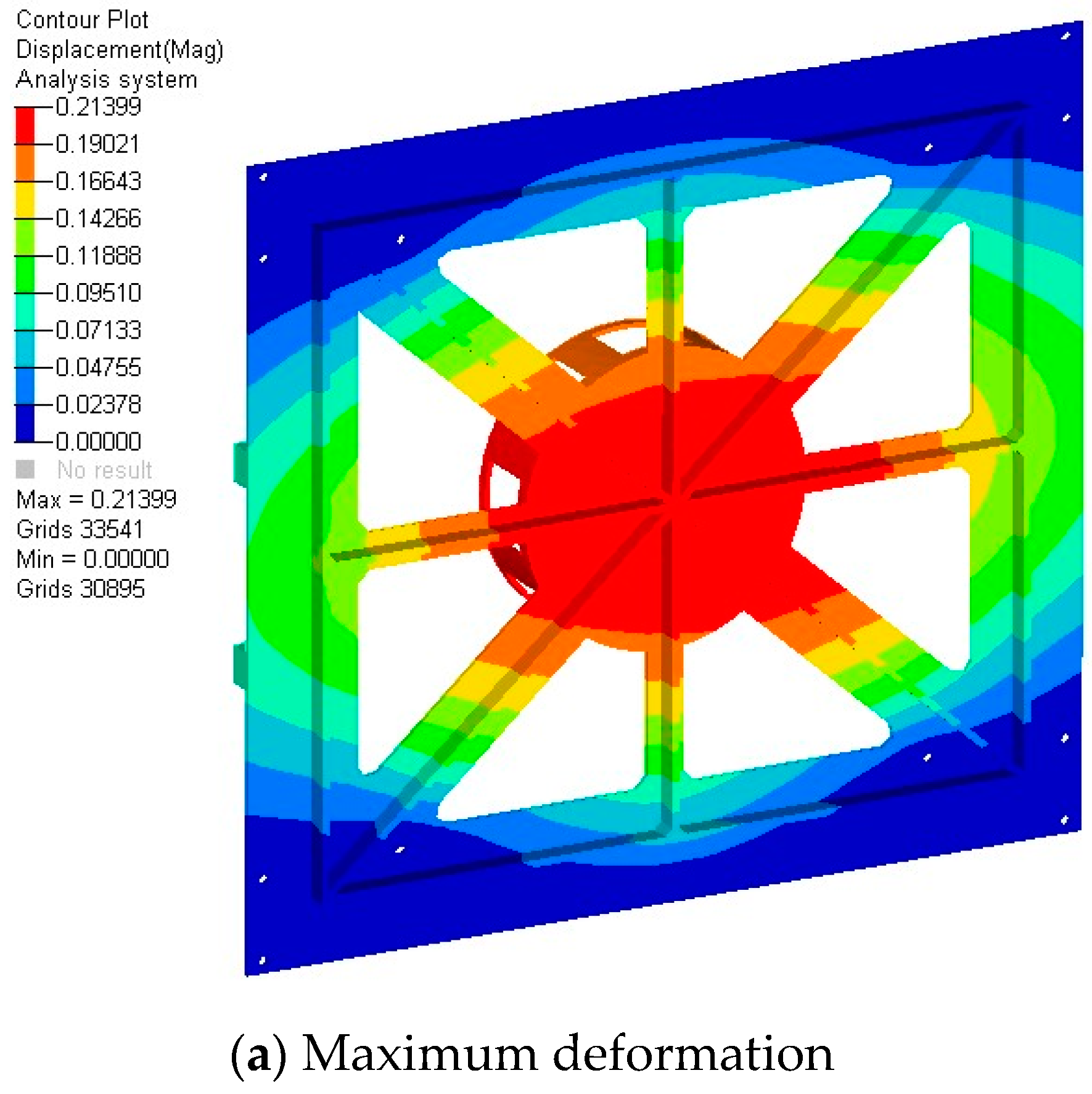
The design load is determined for the following conditions, taking into account the launch vehicle’s mechanical configuration and certain safety factors: 3 g for lateral direction overload and 10 g for vertical direction overload. With the conditions listed above, a quasi-static acceleration analysis is performed in three directions of the separation mechanism. In the quasi-static acceleration analysis, the maximum deformation can result in physical interferences between the components, and the stress induced by the acceleration loads is calculated as the von Mises stress. The maximum stress and deformation of the separation mechanism appear on the bottom plate and push board. Figure 8 illustrates the deformation and stress contours. The maximum deformation and maximum stress values, as well as their locations, are summarized in Table 2.
The bottom plate and push board are made of the aluminum alloy 2A12, and the dynamic parameters are shown in Table 3, which has a 410 MPa failure stress. The structural safety margin is calculated using the safety coefficient of 2.0. As illustrated in Table 2, the simulation results satisfy the design requirements.

4.3. Modal Analysis

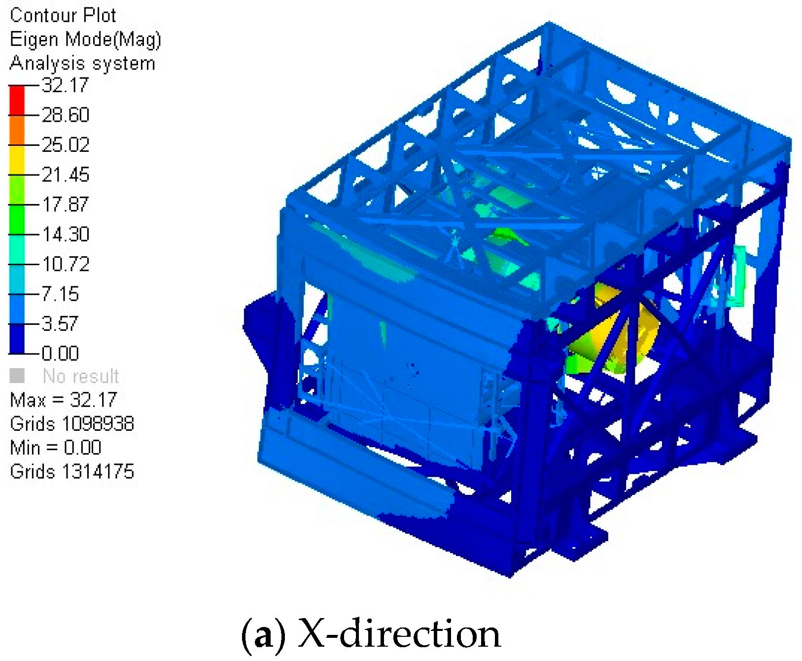
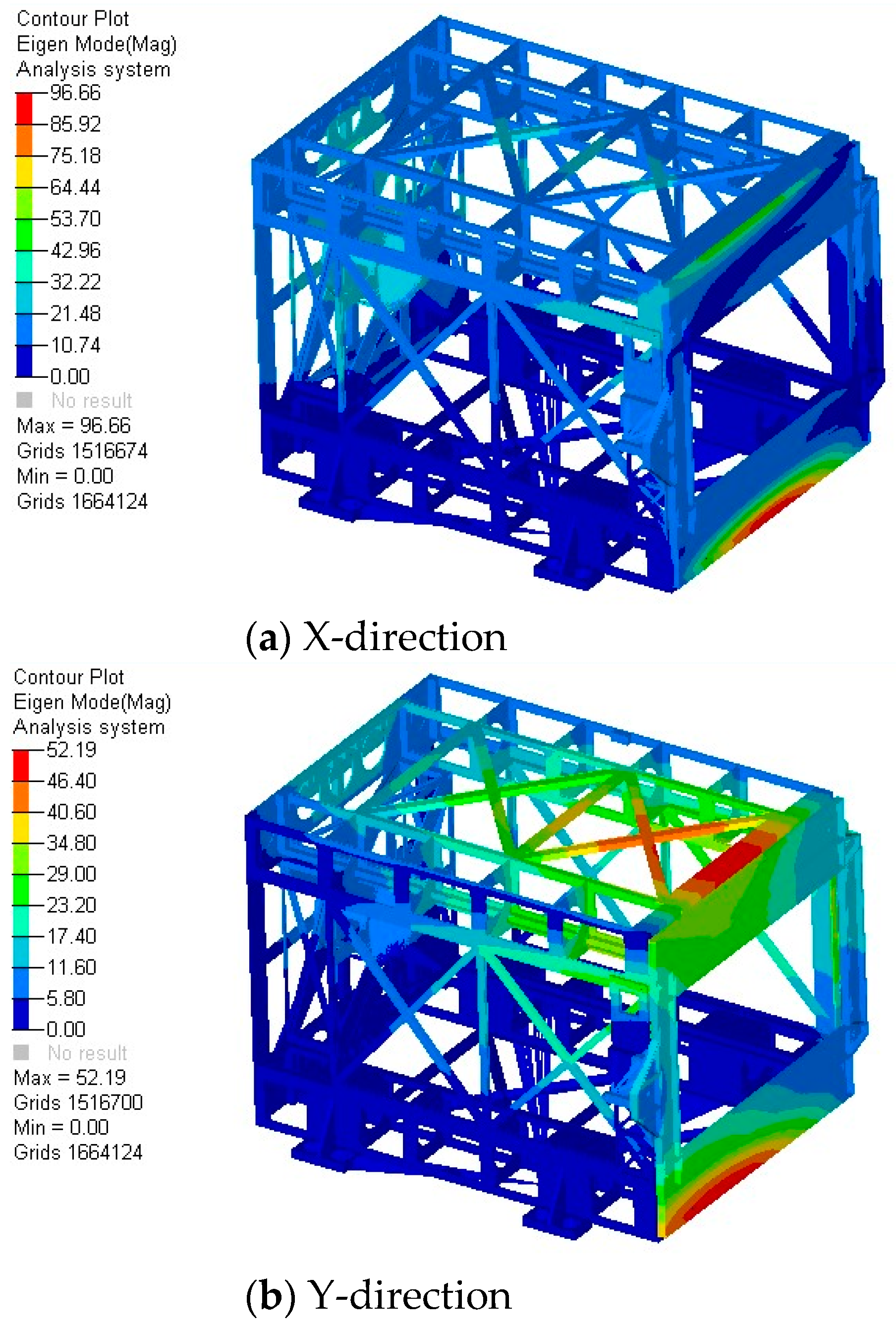
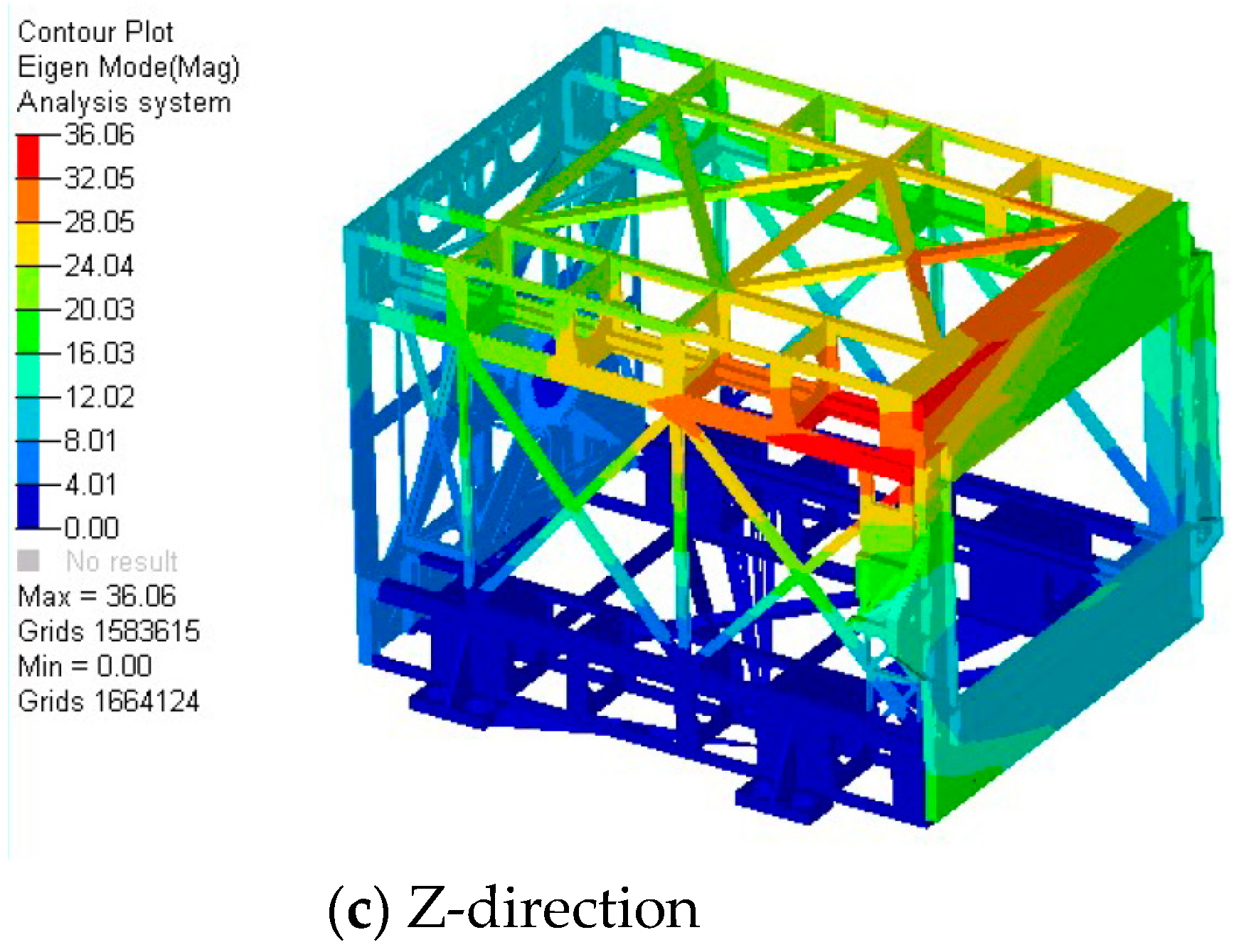
The first step in performing a dynamic analysis is determining the structure’s natural frequencies and mode shapes, taking zero damping into account. The results of this analysis define the structure’s dynamic behavior and can be used to predict how the structure will respond to dynamic loads. The modal analysis of the combination of the separation mechanism and the MF satellite is performed to determine the natural frequency, verify whether the natural frequency meets the requirements of the launch vehicle, and avoid resonance with the launch vehicle during the launch process. The Lanczos algorithm is used to extract the first three modes of the combination of the separation mechanism and the MF satellite, as illustrated in Figure 9, and their natural frequencies are listed in the Table 4. The combination’s natural frequency is significantly higher than the required frequency of the launch vehicle to meet design requirements. The first three modes of the separation mechanism are shown in Figure 10, and the natural frequencies are shown in Table 5. The separation mechanism has a high fundamental frequency and will not resonate with the launch vehicle.

4.4. Random Vibration Analysis

Random vibrations from the spacecraft launch are one of the most severe loads on the structure’s integrity. Random vibration analysis is used to verify the separation mechanism’s strength and structural integrity by introducing random vibrations through the mechanical interface. The purpose of this analysis is to identify the structural response to acoustic noise generated by engine vibration and noise, as well as air friction, during the initial launch phase. The typical way to describe the severity of loading and potential damage caused by random vibration is in terms of the PSD (power spectral density) that the satellite will encounter during launch, which is a frequency domain measure of vibration amplitude power intensity. The average value of all the amplitudes within a given frequency range is used to evaluate the constantly changing acceleration amplitude [37].
The random analysis is used to confirm the separation mechanism and MF satellite’s dynamic mechanical performance. According to Section 4.2 of Table 4, the natural frequency meets design requirements, indicating that the combination’s dynamic stiffness is sufficient to avoid resonance with a launch vehicle carrier when subjected to low-frequency sinusoidal excitation. The random vibration simulation conditions are specified by the launch vehicle design technicians, as shown in Table 6.
The combination of the separation mechanism and the MF satellite was subjected to random vibration analysis using the simulation conditions listed in Table 6. As shown in Figure 11, six sample points were chosen from the MF satellite and two from the separation mechanism, and the results are shown in Table 7. As a result of the analysis, we can see that the response on the MF satellite is extremely low, while the maximum response value is observed on the Z-direction solar panel, which is capable of withstanding a response value of 30 g. Although the separation mechanism’s cover door and side panel have a slightly larger response than the MF satellite’s, the separation mechanism contains no electronic equipment and has a sufficient safety margin to withstand the response. It demonstrates that the system’s dynamic performance meets the engineering application’s requirements.

4.5. Kinematic Analysis

Due to the large size of the MF satellite envelope, there may be a risk of interference between the satellite components and the door cover in the process of satellite separation. It is critical to conduct a kinematic simulation of the satellite separation process to determine whether any components interfere and to verify the mechanism’s rational design. First, the model of the entire satellite was roughened, leaving only its outline, and the satellite’s mass was given an appropriate density of 20 kg. The satellite’s center of mass and moment of inertia corresponds to the three-dimensional model of the MF satellite. The separation spring’s elastic coefficient was chosen to be 252 N/m by taking into account the satellite’s separation velocity and ignoring factors such as friction. Figure 12 illustrates the separation process.
As illustrated in Figure 12, there is no interference between any of the components and the door cover throughout the satellite ejection process. The collision between the protruding object on the satellite surface and the separation mechanism frame, as well as the sailboard and the hatch door, should be given special consideration during the simulation process.
  • Ejecting velocity
To ensure separation safety, the MF satellite’s ejection velocity should be 0.5 m/s–2.0 m/s. Figure 13 illustrates the velocity changes that occur during the satellite’s separation process. The satellite’s final separation velocity is 1.45 m/s, which meets the design requirements, and it takes approximately 0.51 s for the satellite to completely separate from the compressed state. The separation velocity of the satellite can be adjusted according to the specific requirements of different rockets by adjusting the elastic coefficient of the separation spring.
  • Ejecting angular velocity
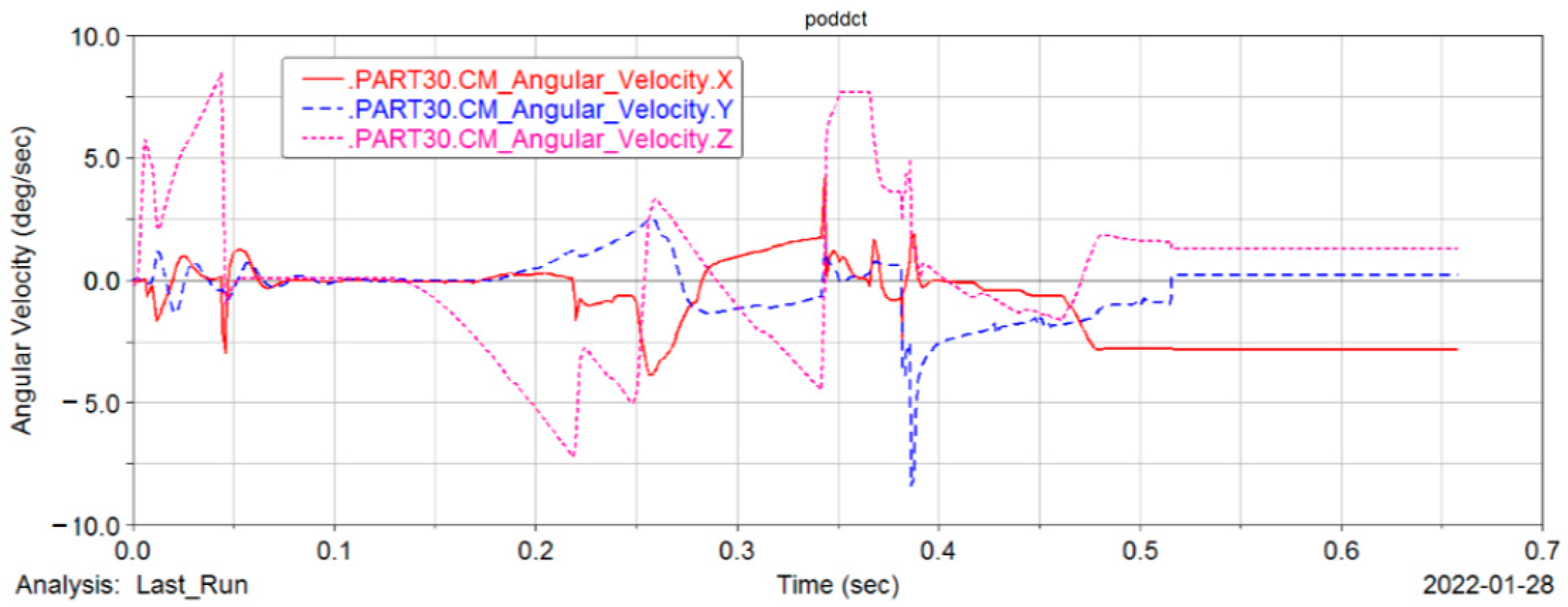
Throughout the movement of the MF satellite, the guide rail will be critical in guiding and adjusting the satellite. The angular velocity variation curve of the MF satellite during the separation process is depicted in Figure 14. As illustrated, the angular velocity of the three axials after they escape the separation mechanism completely is 2°/s, 0.7°/s, and 2.5°/s, respectively. The separation angular velocity meets the index requirements.

5. Experimental Verification

To validate the design of the separation mechanism, vibration and separation tests were conducted. Following the structural analysis, vibration tests on the ground were used to determine the fundamental frequency and structural responses. The separation mechanism’s functionality, including separation velocity and angular velocity, was evaluated through separation tests.

5.1. Vibration Test

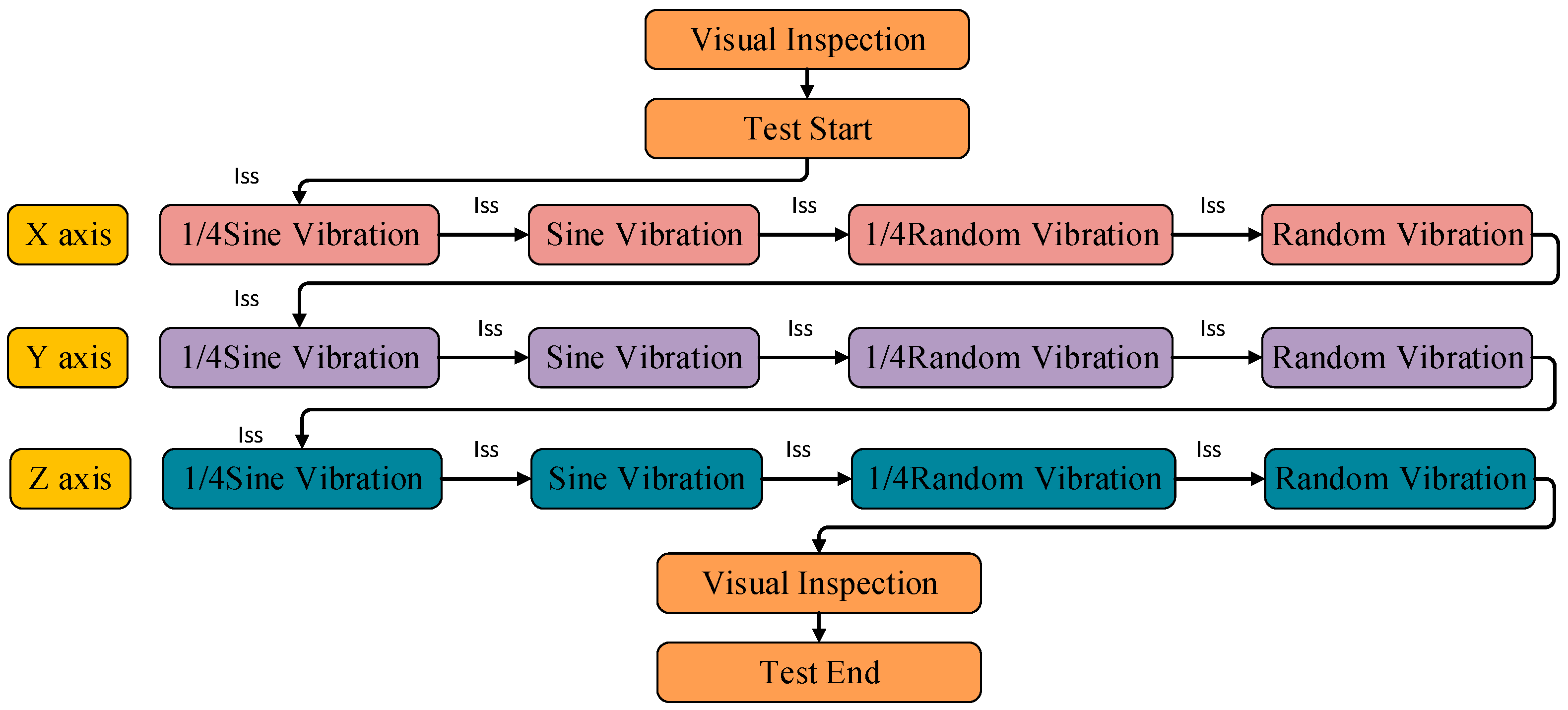
A vibration test was conducted on the combination of the separation mechanism and the MF satellite to evaluate the separation mechanism’s reliability during the launch stage. Six triaxial accelerometers were attached to the surface of the MF satellite and two to the separation mechanism for vibration testing, and the results were compared to those from previous simulations. The test site is depicted in Figure 15, and the vibration-testing procedure is depicted in Figure 16. Individual sine sweeps (Iss) were performed before and after the main tests to assess the separation mechanism and the MF satellite’s physical damage.
The first three-order natural frequencies included in simulations and ground tests are summarized in Table 8. As shown in Table 8, the 1st mode natural frequency measured by the accelerometers during the first and final Iss tests was greater than 60 Hz for all axes, which is sufficiently high to avoid resonance with the launch vehicle. Additionally, the natural frequency changes in the first mode in the three directions before and following the vibration test are within 10%, which meets the tolerance requirements, indicating that the structure is intact and no damage occurred. Comparing the simulation and experimental values of first-order natural frequencies in three directions reveals that the simulation values are all greater than the experimental values and the error ranges are all within 10%, which meets the design requirements. The reason for this phenomenon is that the stiffness ratio of the connection between the MF satellite and the separation mechanism in the simulation model is greater than that in the actual test, and the finite element model can be modified appropriately in the later stage to account for the test structure.
The results of the random vibration test are summarized in Table 9. The satellite’s equipment has extremely small response values that meet the equipment’s requirements. When the test values are compared to the simulation values in Table 7, it is discovered that the test values for the two measuring points on the separation mechanism are very close to the simulation values, whereas the test values for the satellite equipment are all less than the simulation values. This behavior is explained by the fact that the satellite and the separation mechanism are not totally fixed restrictions. There is a slight displacement between the satellite and the separation mechanism during the launch, and this minor displacement and friction absorb the energy that should be transferred to the satellite.

5.2. Separation Test

Due to the effects of thermal expansion and cold contraction, as well as the vacuum environment, the satellite may become stuck during separation. To avoid this, the satellite was separated following the vibration test at room temperature, vacuum high-temperature section, and vacuum low-temperature section, respectively. The satellite was separated successfully under all conditions. The separation mechanism’s functional reliability has been fully validated at room temperature, −40 °C, and 85 °C, respectively. The separation test is illustrated in Figure 17.
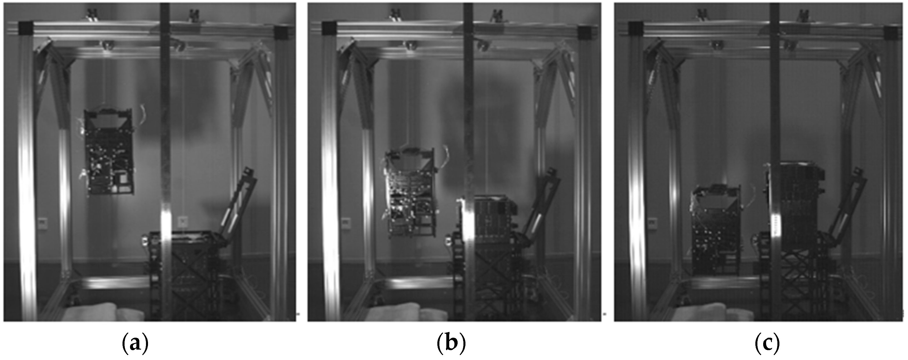
In this paper, a gravity compensation system is created to acquire the satellite’s attitude parameters, such as separation velocity and angular velocity. By using rope suspension to compensate for the satellite’s gravity, this system simulates the microgravity environment of space. The gravity compensation system is comprised of a truss, a ruler, a rope pulley, a rope, a light source, a high-speed camera, a computer processor, and a counterweight satellite. The principle of the measuring system is illustrated in Figure 18. As depicted in Figure 19, the entire satellite separation process was captured using a high-speed camera. Calculations indicate that the instantaneous separation velocity when the satellite is ejected from the separation mechanism is 1.39 m/s, which meets the indicator requirements. The actual separation velocity is less than the simulation value, which is due to the simulation process ignoring the friction between the satellite and the separation mechanism.
Due to the limited energy available to the MF satellites, the separation angular velocity is a critical indicator of the separation process. If the satellite separation angular velocity is too high, it will take a long time for the satellite to perform angular velocity damping. If the satellite’s angular velocity cannot be decreased within the required time range within 4000 s of separation, it will lack the energy required to deploy the solar panels. As a result, the separation mechanism must be capable of separating the satellite with the smallest possible angle of separation. This paper discusses the results of a three-axis gyro for measuring the satellite’s angular velocity during separation. The installation of a three-axis gyroscope within the satellite is depicted in Figure 20.
Several separation tests were conducted to guarantee the test’s reliability, and the separation angular velocity results were statistically presented in the Table 10. The highest separation angular velocity in each separation result was less than 1°/s, as shown in the table, which matches the index’s standards.

6. Conclusions

The launch environment is one of the most hostile environments a satellite will encounter throughout its lifetime. It involves significant risks and the possibility of failure. As a result, it is critical to develop a separation mechanism that is both safe and reliable. In this paper, the separation mechanism for the MF satellite is designed, analyzed, and tested.
The following conclusions can be obtained from the separation mechanism’s theoretical analysis, simulation calculation, ground environment test, and separation test: (1) There are no explosives or redundant separation residues, and the system can be utilized several times on the ground. The separation mechanism is fully integrated, with a basic structure and straightforward processing. The mass ratio of the satellite to the separation mechanism is only 0.29, which is much less than the conventional separation mechanism’s mass ratio, reducing launch costs dramatically. Simultaneously, the interface with the rocket is straightforward, decreasing reliance on the rocket and therefore expanding satellite launch alternatives. (2) The simulation analysis shows that the structural strength of the separation mechanism meets design criteria and has a sufficient safety margin. The fundamental frequency of the assembly is higher than 60 Hz, and there is no resonance with the carrier launch vehicle. The random response value of the satellite is minimal, which conforms to the design index. During the separation process, the MF satellite can efficiently avoid colliding with the door cover and other structures, and the separation velocity and angular velocity match design criteria. (3) The principle prototype test verifies the design and analysis of the separation mechanism. It allows for the efficient and reliable separation of micro-nano satellites.
However, the separation mechanism still has a large optimization space; if the entire structure adopts a method of additive manufacturing, it will improve the separation mechanism’s stiffness and integration while also reducing weight; therefore, this method needs further study.

Author Contributions

Conceptualization, X.Z. and J.L.; data curation, X.Z. and Y.G.; formal analysis, X.Z.; funding acquisition, L.Z.; investigation, X.Z.; methodology, X.Z. and S.C.; project administration, L.Z.; resources, S.C. and L.Z.; software, X.Z.; validation, X.Z.; visualization, L.Z.; writing—original draft, X.Z.; writing—review and editing, X.Z. and C.Z. All authors have read and agreed to the published version of the manuscript.

Funding

This research was funded by the Jilin Province Science and technology development plan project of China, Grant No.20200401011GX.

Institutional Review Board Statement

Not applicable.

Informed Consent Statement

Not applicable.

Data Availability Statement

Not applicable.

Conflicts of Interest

The authors declare no conflict of interest.

References

  1. Nieto-Peroy, C.; Emami, M.R. CubeSat Mission: From Design to Operation. Appl. Sci. 2019, 9, 3110. [Google Scholar] [CrossRef] [Green Version]
  2. Kim, O.-J.; Shim, H.; Yu, S.; Bae, Y.; Kee, C.; Kim, H.; Lee, J.; Han, J.; Han, S.; Choi, Y. In-Orbit Results and Attitude Analysis of the Snuglite Cube-Satellite. Appl. Sci. 2020, 10, 2507. [Google Scholar] [CrossRef] [Green Version]
  3. Liu, J.; Zhao, P.; Wu, C.; Chen, K.; Ren, W.; Liu, L.; Tang, Y.; Ji, C.; Sang, X. SIASAIL-I Solar Sail: From System Design to On-Orbit Demonstration Mission. Acta Astronaut. 2022, 192, 133–142. [Google Scholar] [CrossRef]
  4. Bhattarai, S.; Go, J.-S.; Oh, H.-U. Experimental Cansat Platform for Functional Verification of Burn Wire Triggering-Based Holding and Release Mechanisms. Aerospace 2021, 8, 192. [Google Scholar] [CrossRef]
  5. Bhattarai, S.; Go, J.-S.; Kim, H.; Oh, H.-U. Development of a Novel Deployable Solar Panel and Mechanism for 6U CubeSat of STEP Cube Lab-II. Aerospace 2021, 8, 64. [Google Scholar] [CrossRef]
  6. Kim, S.; Song, C.-M.; Lee, S.-H.; Song, S.-C.; Oh, H.-U. Design and Performance of X-Band SAR Payload for 80 kg Class Flat-Panel-Type Microsatellite Based on Active Phased Array Antenna. Aerospace 2022, 9, 213. [Google Scholar] [CrossRef]
  7. Teng, L.; Jin, Z. Structural Performance Optimization and Verification of an Improved Thin-Walled Storage Tank for a Pico-Satellite. Appl. Sci. 2017, 7, 1168. [Google Scholar] [CrossRef] [Green Version]
  8. Teng, L.; Yang, H.; Jin, Z. Novel Measurement Method for Determining Mass Characteristics of Pico-Satellites. Appl. Sci. 2018, 8, 104. [Google Scholar] [CrossRef] [Green Version]
  9. Kwon, S.-C.; Son, J.-H.; Song, S.-C.; Park, J.-H.; Koo, K.-R.; Oh, H.-U. Innovative Mechanical Design Strategy for Actualizing 80 kg-Class X-Band Active SAR Small Satellite of S-STEP. Aerospace 2021, 8, 149. [Google Scholar] [CrossRef]
  10. Schoolcraft, J.; Klesh, A.; Werne, T. MarCO: Interplanetary Mission Development on a CubeSat Scale. In Space Operations: Contributions from the Global Community; Springer: Berlin, Germany, 2017; pp. 221–231. [Google Scholar]
  11. Poghosyan, A.; Golkar, A. CubeSat evolution: Analyzing CubeSat Capabilities for Conducting Science Missions. Prog. Aerosp. Sci. 2017, 88, 59–83. [Google Scholar] [CrossRef]
  12. Smith, K.; Crisp, N.; Hollingsworth, P. Launch and Deployment of Distributed Small Satellite Systems. In Proceedings of the 65th International Astronautical Congress (IAC), Toronto, ON, Canada, 29 September–3 October 2014. [Google Scholar]
  13. Mehrparvar, A.; Carnahan, J. CubeSat Design Specification Revision 13. In The CubeSat Program; California Polytechnic State University: San Luis Obispo, CA, USA, 2014. [Google Scholar]
  14. Morettini, G.; Zucca, G.; Braccesi, C.; Cianetti, F.; Dionigi, M. CubeSat Spatial Expedition: An Overview from Design to Experimental Verification. IOP Conf. Ser. Mater. Sci. Eng. 2021, 1038, 012026. [Google Scholar] [CrossRef]
  15. Ashida, H.; Fujihashi, K.; Inagawa, S.; Miura, Y.; Omagari, K.; Miyashita, N.; Matunaga, S.; Toizumi, T.; Kataoka, J.; Kawai, N. Design of Tokyo Tech nano-satellite Cute-1.7+ APD II and its operation. Acta Astronaut. 2010, 66, 1412–1424. [Google Scholar] [CrossRef]
  16. Capovilla, G.; Cestino, E.; Reyneri, L.M.; Romeo, G. Modular Multifunctional Composite Structure for CubeSat Applications: Preliminary Design and Structural Analysis. Aerospace 2020, 7, 17. [Google Scholar] [CrossRef] [Green Version]
  17. Lee, M.-J.; Lee, Y.-K.; Oh, H.-U. Performance Evaluation of Hinge Driving Separation Nut-Type Holding and Releasing Mechanism Triggered by Nichrome Burn Wire. Int. J. Aeronaut. Space Sci. 2015, 16, 602–613. [Google Scholar] [CrossRef] [Green Version]
  18. Hwang, H.-S.; Kim, B.; Choi, J.-W. A Compact Non-explosive Separation Device for High Preload and Low Shock. Int. J. Precis. Eng. Manuf. 2014, 15, 83–88. [Google Scholar] [CrossRef]
  19. Wang, W.; Zhang, X.; Hao, D.; Gong, W. Design and Analysis of an Integrated Device for Launch Adapter and Resettable Orbital Deployer for Picosatellites. Proc. Inst. Mech. Eng. Part G J. Aerosp. Eng. 2020, 234, 818–826. [Google Scholar] [CrossRef]
  20. Xie, C.; Xu, Y.; Fu, J.; Wu, C.; Chen, Z. Kinematic System Design of the Pico-Satellite Separation Mechanism. J. Astronaut. 2014, 35, 626–632. [Google Scholar]
  21. Grimm, C.D.; Lange, C.; Lange, M.; Mierheim, O.; Witte, L.; Sasaki, K.; Chand, S.; Ksenik, E.; Grundmann, J.-T.; Ho, T.-M. The MASCOT Separation Mechanism. CEAS Space J. 2020, 12, 343–365. [Google Scholar] [CrossRef] [Green Version]
  22. Glücksberg, A.; Soul, H.; Yawny, A. Releasing Systems for Aerospace Industry Based upon Shape Memory Alloys: Characterization of Materials for Actuators. Matéria 2018, 23, 2. [Google Scholar] [CrossRef]
  23. Nohmi, M.; Yamamoto, T.; Itose, O.; Saitou, J. Rocket Separation Mechanism for Pico Mother and Daughter satellite “KUKAI”. J. Syst. Des. Dyn. 2010, 4, 984–995. [Google Scholar] [CrossRef] [Green Version]
  24. Wang, X.; Liu, W.; Li, X.; Sun, Y. The Shock Response Prediction of Spacecraft Structure Based on Hybrid FE-SEA Method. Appl. Sci. 2021, 11, 8490. [Google Scholar] [CrossRef]
  25. Niu, L.; Tu, H.; Dong, H.; Yan, N. Separation Reliability Analysis for the Low-Shock Separation Nut with Mechanism Motion Failure Mode. Aerospace 2022, 9, 156. [Google Scholar] [CrossRef]
  26. Honghao, Y.; Yifei, Y.; Yifan, L.; Fei, Y.; Jun, W.; Qi, R.; Zongquan, D. Research Progress of Space Non-Pyrotechnic Low-Shock Connection and Separation Technology (SNLT): A review. Chin. J. Aeronaut. 2021; in press. [Google Scholar] [CrossRef]
  27. Brown, J.; Munakata, R. Dnepr 2 Satellite Identification and the Mk. III P-POD. In Proceedings of the CubeSat Developers’ Workshop, San Luis Obispo, CA, USA, 10 April 2008. [Google Scholar]
  28. Tu, Q.; Jiang, M.; Qi, W.; Li, Y.; Liu, Y. The Design and Analysis of Picosatellite Orbital Deployer Based on Shape Memory Alloy Release. In Proceedings of the 2017 International Conference on Computer Systems, Electronics and Control (ICCSEC), Dalian, China, 25–27 December 2017; pp. 1689–1694. [Google Scholar]
  29. Ali, M. Design and Implementation of Ground Support Equipment for Characterizing the Performance of XPOD and CNAPS & Thermal Analysis of CNAPS Pressure Regulator Valve; University of Toronto: Toronto, ON, Canada, 2009. [Google Scholar]
  30. Akagi, H.; Takata, M.; Watanabe, H.; Sano, T.; Oikawa, K. Kibo’s Contribution to Broadening the Possibilities for Micro-Satellite. In Proceedings of the 14th International Conference on Space Operations, Daejeon, Korea, 16–20 May 2016; p. 2517. [Google Scholar]
  31. Dobrowolski, M.; Grygorczuk, J.; Kedziora, B.; Tokarz, M.; Borys, M. DRAGON-8U Nanosatellite Orbital Deployer. In Proceedings of the 42nd Aerospace Mechanism Symposium, Baltimore, MD, USA; 2014. [Google Scholar]
  32. Roemer, S.; Stoltz, S. SPL Light Weight Deployment Mechanism for Single CubeSats and DPL for double CubeSats. In Proceedings of the Symposium on Small Satellite Systems and Services (4S), Funchal, Madeira, Portugal, 31 May–4 June 2010. [Google Scholar]
  33. Aslan, A.R.; Bernal, C.; Puig-Suari, J. I-4b: Deployment Systems. In Nanosatellites Space and Ground Technologies, Operations and Economics; Wiley: Hoboken, NJ, USA, 2020; pp. 375–397. [Google Scholar]
  34. Jiang, C.; Wang, Z.; Zhang, Y. Development of the New Approach of Formation Initialization Using Spring Separation Mechanism Considering J2 Perturbation. Adv. Space Res. 2015, 55, 2616–2627. [Google Scholar] [CrossRef]
  35. Hegde, S.R.; Sahay, D.; Sandya, S.; Sandeep, G.; Nikhilesh, K. Design and Development of Inter-Satellite Separation Mechanism for Twin Nano Satellite—STUDSAT-2. In Proceedings of the 2016 IEEE Aerospace Conference, Sky, MT, USA, 5–12 March 2016; pp. 1–8. [Google Scholar]
  36. Puig-Suari, J.; Turner, C.; Ahlgren, W. Development of the Standard CubeSat Deployer and a CubeSat class PicoSatellite. In Proceedings of the 2001 IEEE Aerospace Conference Proceedings (Cat. No. 01TH8542), Sky, MT, USA, 10–17 March 2001; Volume 341, pp. 1, 341–347, 353. [Google Scholar]
  37. Park, Y.-K.; Kim, G.-N.; Park, S.-Y. Novel Structure and Thermal Design and Analysis for CubeSats in Formation Flying. Aerospace 2021, 8, 150. [Google Scholar] [CrossRef]
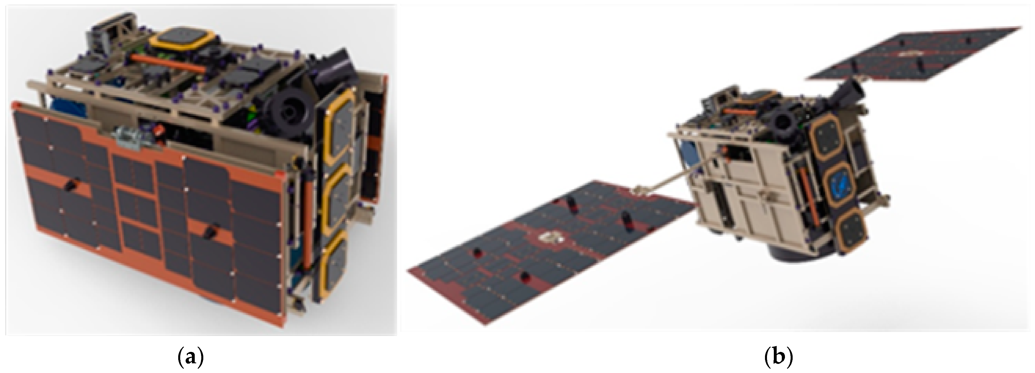
Figure 1. The MF satellite model. (a) Launch state; (b) On-orbit state.
Applsci 12 05997 g001
Figure 2. Exploded view of the MF satellite.
Applsci 12 05997 g002
Figure 3. Exploded view of the separation mechanism.
Applsci 12 05997 g003
Figure 4. Mechanical interface diagram for the separation mechanism and the MF satellite.
Applsci 12 05997 g004
Figure 5. OLMDC model.
Applsci 12 05997 g005
Figure 6. Schematic diagram of the door cover opening and locking mechanism.
Applsci 12 05997 g006
Figure 7. Finite element analysis model.
Applsci 12 05997 g007aApplsci 12 05997 g007b
Figure 8. Quasi-static acceleration analysis results.
Applsci 12 05997 g008aApplsci 12 05997 g008b
Figure 9. First three-order natural frequencies of combination.
Applsci 12 05997 g009aApplsci 12 05997 g009b
Figure 10. First three-order natural frequencies of the separation mechanism.
Applsci 12 05997 g010aApplsci 12 05997 g010b
Figure 11. The arrangement of three-axis accelerometers.
Applsci 12 05997 g011
Figure 12. Separation process.
Applsci 12 05997 g012
Figure 13. The curve of separation velocity variation.
Applsci 12 05997 g013
Figure 14. The curve of separation angular velocity variation.
Applsci 12 05997 g014
Figure 15. Vibration testing site.
Applsci 12 05997 g015
Figure 16. Vibration testing procedure flow diagram.
Applsci 12 05997 g016
Figure 17. Separation test. (a) room temperature; (b) vacuum high-temperature; (c) vacuum low-temperature.
Applsci 12 05997 g017
Figure 18. Gravity compensation system.
Applsci 12 05997 g018
Figure 19. Separation process. (a) Initial state; (b) Intermediate state; (c) Popup state.
Applsci 12 05997 g019
Figure 20. Three-axis gyro within the satellite.
Applsci 12 05997 g020
Table 1. Indexes for separation mechanism.
NOIndex NameIndex Value
1Structural parametersSize (mm)≤400 × 500 × 550
Mass (kg)≤6
2Separation attitudeSeparation velocity (m/s)0.5–2
Separation angular velocity(°/s)≤3
3Natural frequency3 axis (Hz)≥50
4OverloadLateral direction(g)3
Vertical direction(g)10
Table 2. Quasi-static acceleration analysis results.
LocationMaximum
Deformation
Maximum StressFailure
Stress
Safety
Coefficient
Safety
Margin
Bottom plate0.214 mm24.3 MPa410 MPa2.07.4
Push board0.162 mm17 MPa410 MPa2.011.1
Table 3. Dynamic parameters of 2A12 aluminum alloy.
Young’s Modulus (MPa)Poisson’s RatioDensity (kg/mm3)Failure Stress (MPa)
70,0000.332.7410 MPa
Table 4. Modal analysis results of the combination.
NoFrequency (Hz)Mode Shape
177.7X-Direction
270.8Y-Direction
382.6Z-Direction
Table 5. Modal analysis results of separation mechanism.
NoFrequency (Hz)Mode Shape
1243.6X-Direction
2168.8Y-Direction
3116.5Z-Direction
Table 6. Random vibration test conditions.
Frequency (Hz)Acceptance Conditions
Power Spectrum Density (g2/Hz)Total RMS of Acceleration (g)
Value20~150+3 dB/oct7.19
150~2800.04
280~3200.15
320~3800.10
380~8500.05
850~10000.02
1000~20000.005
Direction3 directions
Time1 min for each direction
Table 7. Results of random vibration analysis.
No.LocationX-Response/grmsY-Response/grmsZ-Response/grms
A1Camera mounting point4.35.66.3
A2Camera backplate4.25.05.7
A3Primary mirror of the camera3.75.15.5
A4Secondary mirror of the camera5.55.55.6
A5OBHD4.94.45.4
A6Solar panel5.69.311.6
B1Cover door14.98.712.0
B2Side panel6.54.612.1
Table 8. Summary of natural frequency.
DirectionXYZ
1st mode natural frequencyNumerical analysis77.770.882.6
First Iss test71.363.978.4
Final Iss test72.162.872.7
Natural frequency changeNumerical analysis/First ISS test−8.2%−9.7%−5.1%
First/Final Iss test+1.1%−1.8%−7.2%
Table 9. Results of random vibration test.
No.LocationX-Response/grmsY-Response/grmsZ-Response/grms
AnalysisTestAnalysisTestAnalysisTest
A1Camera mounting point4.32.25.62.66.33.1
A2Camera backplate4.22.15.01.65.72.1
A3Primary mirror of the camera3.71.65.12.15.51.8
A4Secondary mirror of the camera5.54.25.52.15.65.6
A5OBHD4.92.94.41.95.42.3
A6Solar panel5.64.29.37.311.611.7
B1Cover door14.915.48.78.412.011.5
B2Side panel6.56.74.64.212.112.8
Table 10. Test value for the angular velocity.
NoX (°/s)Y (°/s)Z (°/s)
10.090.320.58
20.150.350.57
30.130.300.61
40.110.330.63
50.080.390.59
Publisher’s Note: MDPI stays neutral with regard to jurisdictional claims in published maps and institutional affiliations.