4.2. Phantom Experiments
In this study, two sets of phantom experiments were performed to evaluate the system performance and compare the three different push beam generation methods. In the homogeneous part of the study, all of the techniques performed similarly, even though there were significant differences between the methods, especially in terms of the energy that was transmitted by a single shear wave source. A closer look at the acquired SWS maps exposed variations in the SWS estimates, depending on the pixel position. FCUSE showed increased SWS values near the center, while these were near the sides of the FOV during the FCUSE-SSI method. The SWS estimation accuracy could depend on the local shear wave energy, as stronger displacement signals could correlate better. Because the total energy that was utilized by each technique was the same, the shear wave energy distribution, as defined by Equation (
8), resulted in a different energy distribution in each technique (
Figure 16). The regions of reduced energy on the push beam axis or at depths below 30 mm could be clearly seen, which was possibly the result of diffraction and attenuation. The local energy was especially high in the regions that were covered by shear waves from multiple sources. During the FCUSE method, the energy was distributed close to the focal points, which were positioned shallower than 30 mm (as in the transmit plan). This was the result of the increased
value of 2.4. In the SSI and FCUSE-SSI techniques, the energy was distributed over a large part of the FOV, although the energy levels were not as high as those in the FCUSE method.
The reconstructed SWS maps and their quality metrics confirmed that all three methods exhibited similar performances and that none of them were generally superior over the others. This was not unexpected, since the total electrical energy that was used for the push excitation was the same in all cases. The differences between the techniques could, in most cases, be explained by the differences between the shear wave energy distributions within the ROIs. Due to the lack of consistency and small differences between the quality metrics of the analyzed methods, only a simplified comparison could be conducted in this study. For inclusion SNR, the FCUSE method performed favourably compared to the other methods, showing the best results in seven out of nine measurements; however, it suffered from poor background SNR. The SSI method outperformed the other techniques in the homogeneous experiments and with regard to background bias in the heterogeneous experiments, for which it had the lowest bias in eight out of nine measurements. Finally, the FCUSE-SSI method performed well in terms of background SNR and CNR but suffered from poor inclusion SNR. It must also be noted that the comparison was not completely fair as the SSI method was the only technique that used three acquisitions to reconstruct a single SWS map, while the other techniques only used one. The push excitation energy was the same, but the SSI method required three tracking sequences instead of one and, as a result, produced a dataset for processing that was three times larger. Overall, the techniques appeared to be complimentary and could be used in conjunction with a series of acquisitions to achieve a synergy effect.
One striking result was the bias that was observed in all of the estimates. The pixel-wise SWS estimate distribution for each homogeneous phantom image (
Figure 17) confirmed that in each technique, almost all pixels had values that were biased higher than the nominal value. The bias observed that was in the heterogeneous phantom experiments was even higher, ranging from −30.4% (SSI;
mm type III inclusion) to +23.8% (FCUSE-SSI;
mm type II inclusion). In general, for all techniques and all inclusion types, the absolute bias increased as the inclusion diameter became smaller. For the largest target dimension that was used (
mm), the observed bias was in the range of −9.6 to −7.9% for type IV inclusions, 1.8 to 4% for type III inclusions and 14.8 to 16.4% for type II inclusions. Furthermore, it should be noted that the SWS bias resulted in an even higher bias in the elasticity maps because the Young’s modulus was proportional to the square of the SWS (see Equation (
2)).
In this work, the values that were provided by the phantom manufacturer were treated as the nominal values. Those values had a 5% tolerance for a given stiffness. Nevertheless, in the homogeneous case, all of the estimated average SWS values that were obtained by all three techniques were beyond this margin, which was a
m/s maximum for background material. The same applied to heterogeneous phantom results in the majority of cases. Assuming that the real SWS values were within the margins provided by the manufacturer, this led to the conclusion that there were one or more bias sources present in the system. The bias effects in the SWE technique were investigated in works by other research groups, in which it was confirmed that the SWS values that were produced with the ARF and ToF approaches depend on the transducer, aperture size and pixel position. One possible cause of bias could be an undesired push beam intensity field as wide beam widths in the elevation direction can generate significant out-of-plane shear waves that bias the SWS estimates high [
29]. It has been reported that this effect is stronger when in close proximity to the push beam axis in the lateral direction and with an increasing distance from the beam focus in the axial direction. In this study, the push beam focal point depth was set close to the probe elevation focus depth (25 mm) and SWS estimates that were close to the shear wave sources were not used. Although those measures could minimize the bias, the effects could not be dismissed entirely. Diffraction could be another cause of the bias. For a push beam, diffraction produces an acoustic intensity before and beyond the depth of focus, which generates additional shear waves in non-focal regions and interferes with shear waves from the focal point, thereby biasing the results high [
29]. This effect is stronger for wider apertures. Furthermore, it was assumed in the data processing implementation that the shear waves would only propagate in the lateral direction, which was reported to be another possible reason for bias [
21]. Finally, the biased results could be also caused by system-dependent parameters, such as PRF error and transducer parameter mismatches between the real values and those used in the software or phase aberration [
30]. Interestingly, similar levels of bias have been reported in other studies that used the same phantom and commercial systems [
31,
32]. In summary, the reconstruction of SWS maps is a complex multi-step process and bias can arise at each processing stage. This then propagates through the processing pipeline, resulting in errors in the estimated SWS maps. Identifying the bias source could require a detailed analysis and was beyond the scope of this article. The same applies to the estimate variance. Exploring the effects of various system components on the bias and accuracy will be the subject of future work.
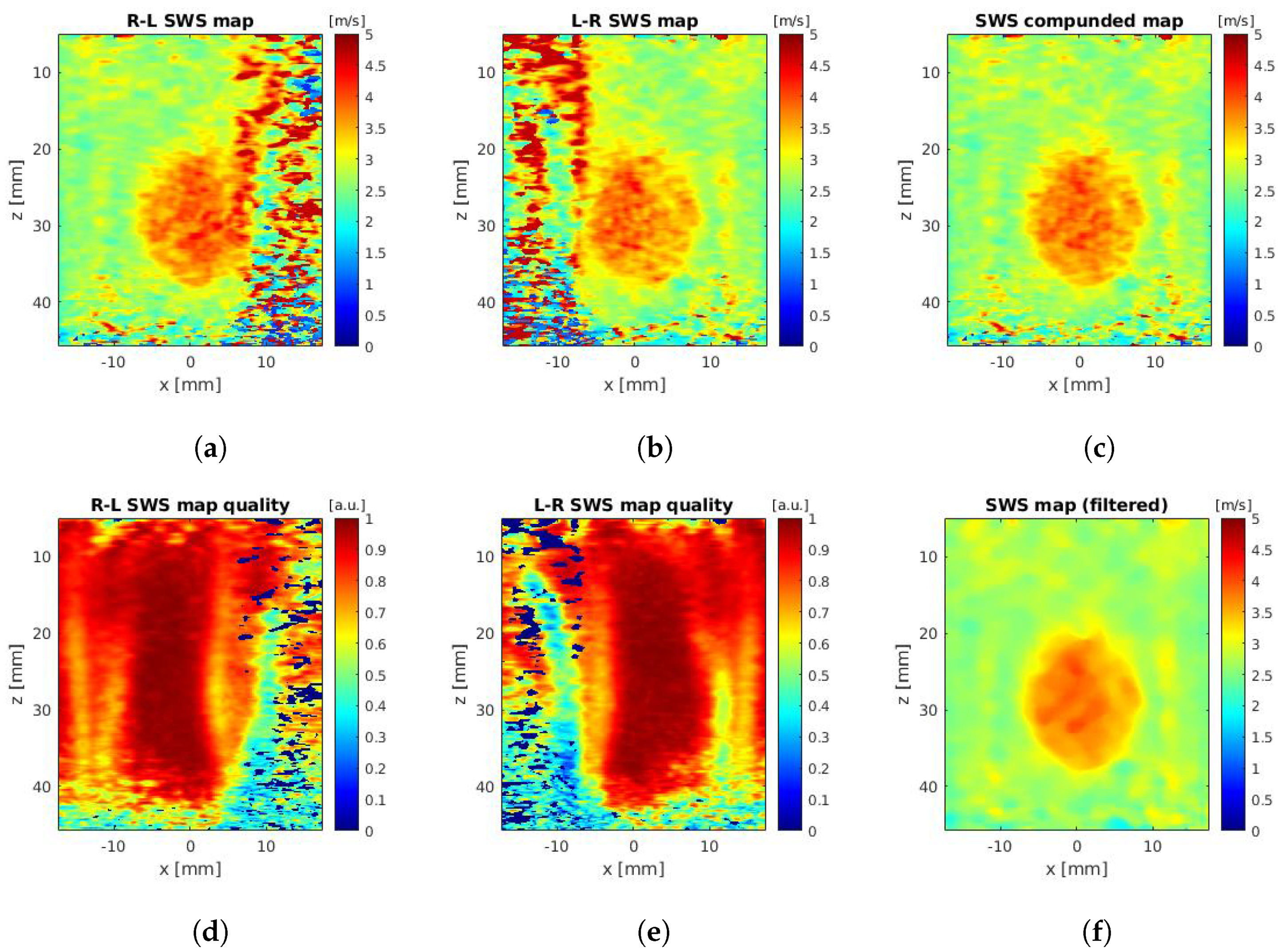
No systematic evaluation of the SWS map resolution was performed in this study. The resolution depends on many factors that are related to shear wave excitation, SWS estimation method and the parameters that are used for its calculation [
6]. Importantly, there is a trade-off between the accuracy and spatial resolution that is adjusted by the lateral correlation window sizes that are used in the SWS estimation [
6,
28]. In this study, only a single lateral correlation window size was used (
mm) in the heterogeneous experiments, which was found experimentally. In spite of that, the SWS maps of the various inclusion types and diameters (
Figure 12,
Figure 13 and
Figure 14) provided a brief overview of the system capabilities in terms of resolution. For instance, the
mm type III inclusion could barely be seen in the estimated SWS map due to poor contrast, whereas the type IV and type II inclusions were easily detectable. In addition, along with degrading the spatial resolution, increasing the lateral kernel size could also cause some level of averaging and shift the reconstructed inclusion values toward the SWS value of the background. This was in line with the observations of Racedo et al. [
28]. This averaging effect could explain the inclusion average SWS results, which varied with respect to the inclusion diameter.
This study had some limitations. First of all, for the purpose of clarity, there was no systematic analysis of the push beam design parameters in the evaluated methods, such as focusing depth, the number of parallel beams of focal points or center frequency. Only arbitrarily applied settings were used, which might not have been fully representative of a given technique. However, an analysis of the impacts of those parameters on the SWE imaging quality has been covered in detail in other works. Secondly, only a single homogeneous phantom was used, so the evaluation of the performance of the three methods in the homogeneous experiments was limited.


