Article

Integrated Switched Reluctance Starter/Generator for Aerospace Applications: Particle Swarm Optimization for Constant Current and Constant Voltage Control Designs

by
Mohamed M. Sedky
1,
Wessam E. Abdel-Azim
1,
Ayman S. Abdel-Khalik
1 and
Ahmed M. Massoud
2,*
1
Department of Electrical Engineering, Alexandria University, Alexandria 21544, Egypt
2
Department of Electrical Engineering, Qatar University, Doha 2713, Qatar
*
Author to whom correspondence should be addressed.
Appl. Sci. 2022, 12(15), 7583; https://doi.org/10.3390/app12157583
Submission received: 6 May 2022 / Revised: 5 June 2022 / Accepted: 7 June 2022 / Published: 28 July 2022

Abstract

:
Extensive efforts have been made to develop reliable and efficient onboard generation systems for electric aircraft. Due to the inherited robustness, Switched Reluctance Machines (SRMs) have attracted attention as a promising candidate for an integrated starter/generator in aerospace applications. This paper presents two modes of operation: Constant Current (CC) and Constant Voltage (CV). A Particle Swarm Optimization (PSO)-based tuning approach is employed to optimize the controller of a Switched Reluctance Generator (SRG). The presented controller is evaluated using a three-phase 6/4 SRG. The Control-Hardware-in-the-loop (CHiL) has been used to elucidate the viability of the explored control concept practically.

1. Introduction

Electric aircrafts increase safety and reliability, impact the environment positively, and enhance system efficiency. Extensive efforts have been made to develop reliable and efficient onboard generation systems [1]. Typically, in aviation systems, the starting (through the devoted motor) and generation (through the generator) functionalities are decoupled, therefore increasing cost, size, weight, and complexity [2,3]. An integrated starter/generator (ISG) has been introduced as a possible solution, either using a permanent magnet machine or a switched reluctance machine [4,5]. While the first has high power density and efficiency, the latter overcomes the issues relevant to flexibility and stability, providing a simple structure, wide speed range, and reduced maintenance requirements. A switched reluctance machine supporting starting and acting as a generator represents a promising solution for electric aircraft (integrated starter/generator system) [6]. The ISG has been extended to some types of unmanned aerial vehicles [2]. In this case, the SRM acts as a motor to spin the engine (starting up) until the idle speed is reached. Then the SRM enters the generation mode, acting as a prime mover to supply the onboard loads.
Although the switched reluctance machine (SRM) is not a new concept, commercial versions have only been available recently. The SRM is an excellent choice for various applications because of its multiple benefits, including the simple and durable structure, high dependability, suitability for operation at high temperatures and speeds, and easy winding design [7]. These motors are commonly proposed as a replacement for induction machines and permanent magnet synchronous machines in a variety of situations when these machines’ operating conditions are insufficient for the targeted applications, such as aerospace, electric vehicles (EVs) [8,9,10], motorcycles, and oilfield equipment (such as beam and vertical pumps). A body of research has been conducted on the motoring mode of SRM, including enhancement performance, design, and control. Recently, scientists have started investigating the generation mode of SRM in different applications.
Switched Reluctance Generators (SRGs) are used in various industrial applications, such as aviation power systems, electrical traction, battery charging, and wind power generation. In addition, thanks to the absence of windings and/or permanent magnets on the rotor, SRG offers several advantages over other generator types, including high power density, superior performance over a wide speed range, low production cost, high efficiency, and high fault tolerance [11,12,13,14]. The SRG works on the decreasing part of its inductance profile [15,16]. The SRG drive system consists of the machine, the converter, and the controller. Due to their attractive features, SRGs have been proposed for electric vehicles, wind energy, and aircraft applications [6,17]. The generation mode of SRM is enabled by exciting different phases during the negative slope of the inductance curve. The drive circuit excites different phases at regular intervals, representing the excitation period that extends between turn-on, θon, and turn-off, θoff angles. The generation period is the interval between turn-off, θoff, and when the phase current ceases and reaches zero [18].
Several control strategies for SRG over a wide speed range at constant output voltage have been provided in [19,20]. Various studies dealing with turn-on/-off angles to improve machine efficiency have also been introduced [21,22,23,24], while the angle control for maximum output power is achieved in [25]. Detecting the turn-on/off angles to deliver maximum power was used in [23,26]. A fuzzy logic controller has been employed to control the output power by regulating the turn-on angle while keeping a constant turn-off angle [27,28,29,30]. The Proportional–Integral–Derivative controller, PID, is commonly used in industrial applications [21,31,32], increasing system responsiveness, reducing steady-state error, and enhancing system stability.
Particle swarm optimization (PSO) [33] is an effective optimization method. In addition to its simplicity of implementation, PSO can address optimization problems with multiple local optima. PSO is a bio-inspired algorithm that is simple in searching for an optimal solution in the solutions space. PSO has an inherent guidance strategy that allows PSO solutions to obtain essential data from improved solutions for further enhancement. The objective function is independent of the gradient of the objective with reduced hyperparameters, allowing for faster convergence. PSO in electric drive systems has been explored extensively in the literature. To estimate the electrical and mechanical properties of PMSMs, the PSO algorithm is used along with learning techniques [34]. Based on the PSO method, a rapid and systematic approach for estimating the mechanical parameters of SRM has been proposed [35]. Using the PSO approach, maximum power extraction from an SRG-based wind power-producing system was achieved [36]. The PID controller generally increases system responsiveness, steady-state error, and system stability. In addition, the PID parameters are affected by system characteristics. As a result, optimum PID settings are required to achieve the intended performance. PID settings may be fine-tuned in two ways: Traditionally and intelligently. Particle Swarm Optimization (PSO), Ant Colony Optimization (ACO) [37], Whale Optimization Algorithm (WOA) [38], Artificial Bee Colony (ABC) [39], Firefly Algorithm (FA) [40], Differential Evolution (DE) [41], Gravitational Search Algorithm (GSA) [42], Bat Algorithm (BA), Pattern Search Algorithm (PSA), and Genetic Algorithm (GA) are examples of heuristic optimization methods that can be employed to tune the PID controller parameters [43,44]. The PSO technique has been used for tuning the PID controller in several applications [45,46,47,48,49,50,51]. For instance, the PSO technique has been used for tuning the PID controller of an SRG employed in wind energy applications [45]. Using the PSO approach, the optimal firing angle for SRG in the current-controlled mode has been examined, balancing the energy efficiency maximization and torque ripple minimization. The major goal of [46] was to improve the SRG′s efficiency, hence, a tracking algorithm was created and integrated with the PID controller. This algorithm aims to follow the SRG′s highest efficiency point, regardless of the setpoint or the generator′s rotor speed. Combining the PID controller with the MEPT algorithm increases SRG efficiency, making the machine more appealing for wind generation systems.
In [49], PSO has been employed for digitally tuning a PID controller for a CAN-based dc motor. In [50], PID controller tuning using PSO has been addressed considering the system robustness. In [51], PSO has been explored for tuning a PID controller using AVR systems.
This paper presents two modes of operation, namely Constant Current (CC) and Constant Voltage (CV) modes, for SRG as an ISG in aerospace applications. A Particle Swarm Optimization (PSO)-based tuning approach is employed to optimize the PID controller of an SRG. The proposed controller optimally adjusts both the turn-on and turn-off angles under possible load types (CV and CC loads). The paper structure is as follows. Section 1 addresses the operation and mathematical modeling of a 6/4 SRG employed in this study. Section 2 provides the PSO-based algorithm for fine-tuning the PID. In Section 3, the employed Simulink/MATLAB model with the suggested control system is given. Section 4 provides the proposed controller under different schemes, namely, controlled turn-off angle, controlled turn-on angle, and controlled both turn-on and off angles. Furthermore, the controller generates the needed turn-off angle while the turn-on is fixed and generates the required turn-on angle while the turn-off is fixed. The OPAL-RT platform is used for experimental validation given in Section 5. Finally, the main conclusions are summarized in Section 6.

2. Research Significance

The contributions of this paper are as follows:
  • Applying the PSO algorithm for fine-tuning the PID parameters of a current-controlled SRG.
  • The ability of the proposed controller to generate the required turn-off or turn-on angles for constant output voltage or constant output current loads in aerospace applications.
  • The proposed controller system can effectively limit the maximum value of output voltage or output current in the electric aircraft system as a safety precaution.
  • The trade-off between the turn-on angle and turn-off angle control performance is investigated.

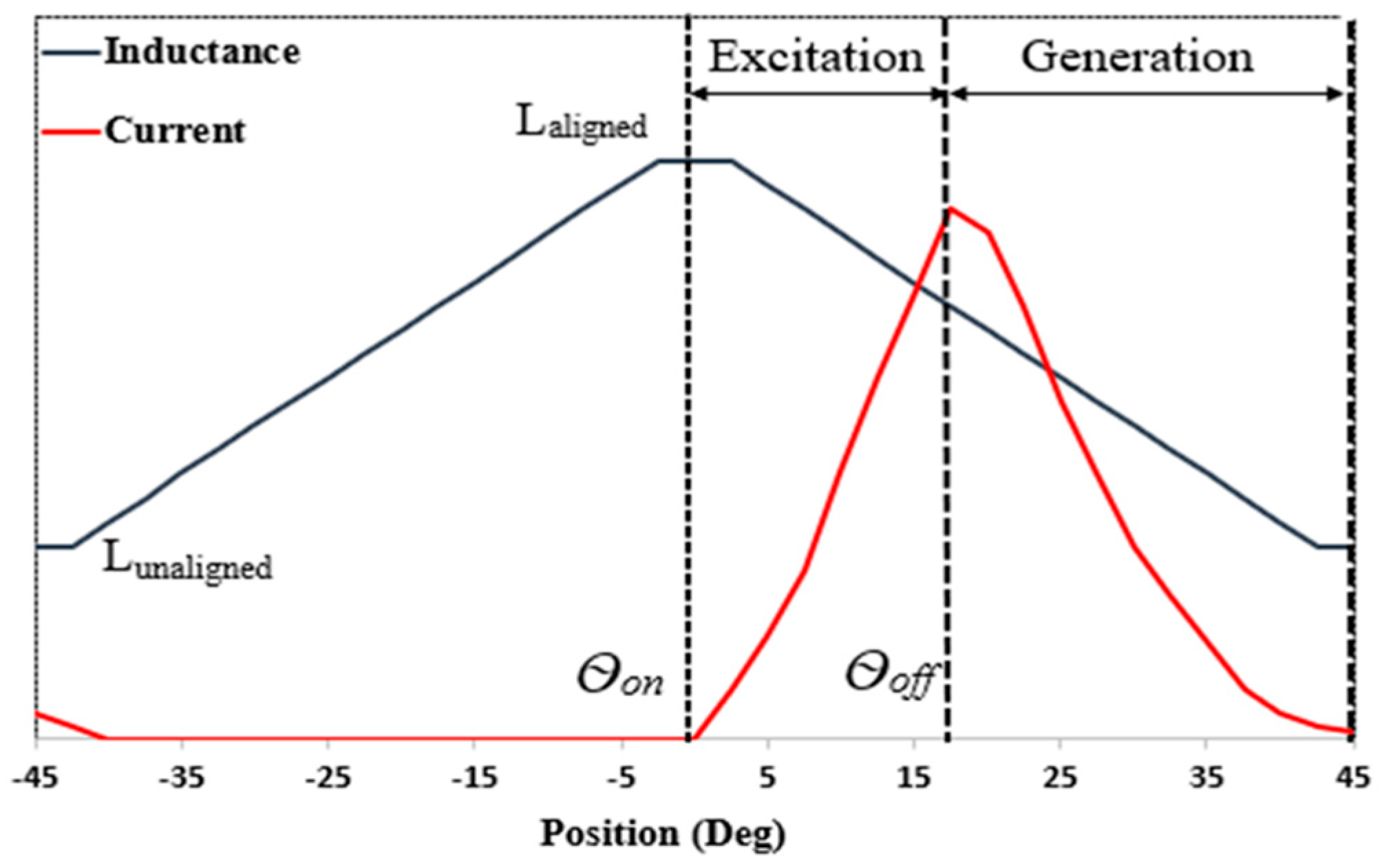
3. A 3 Phase 6/4 SRM Mathematical Model and Operation

The layout of a three-phase machine with six poles on the stator and four poles on the rotor is shown in Figure 1. The stator is equipped with concentrated winding, while the rotor has no winding or magnets. The SRG properties are determined by the machine structure and magnetization characteristics of the laminations, as well as the converter architecture and controller methods.
The voltage equation of each motor phase is given by
V = R i + d λ ( i , θ ) d t
i is the phase stator current in A, R is the phase resistance in Ω, and λ is the stator flux per phase in Wb, where
λ ( i , θ ) = L ( i , θ ) · i
The phase inductance L(i,θ) in H depends on the rotor position, maximum at the aligned position, and minimum at the unaligned position. Using (1) and (2) leads to the general excitation voltage equation for SRM (3).
V = R i + L   d i d t + i d L ( i , θ ) d θ d θ d t
where the last term is the induced emf in V. In SRG, the excitation is applied at the position of maximum inductance, which is the turn-on angle θon, and the turn-off angle θoff at the negative slope of the inductance profile
T e =   1 2 i 2   d L ( θ , i ) d θ
The electromagnetic torque T e is seen to be dependent on the rate of change of phase inductance due to rotor position and the square of phase current. As a result, the drive system applies the current pulses when ( d L d θ > 0 ) under motoring operation, and when ( d L d θ < 0 ) under generating mode. The asymmetric half-bridge (AHB) converter is the most commonly used converter in such drive systems. SRG operates during the excitation period and generation period, where the excitation period is defined during the turn-on and turn-off angle of the AHB [46]. The inductance profile and the current waveform for one phase of SRG are illustrated in Figure 2.

4. Particle Swarm Optimization (PSO)

In 1995, Kennedy and Eberhart introduced Particle Swarm Optimization. Birds′ social behavior inspired the fundamental concept [33]. This method effectively tackles a wide range of complex optimization issues. The PSO approach begins by evaluating a swarm of solutions, or a population of solutions. This swarm comprises particles, each of which proposes an iteration solution until the optimal value for the objective function is found. These particles seek space and adjust their velocities to find the best answer.
The PSO algorithm is made up of ‘n’ particles. The case of each particle changes depending on the best optimization of the particle′s location, and the swarm′s position should be optimized as much as possible, where:
V i ( k + 1 ) = w V i k + C 1 rand 1 ( P b e s t S i k ) + C 2 rand 2 ( g b e s t S i k )  
S i k + 1 = S i k + V i k + 1  
w = w m a x ( w m a x w m i n ) I t e r m a x I t e r  
where Vi and Si are the particle velocity and position, respectively; C1 and C2 are cognitive and social learning factors; w is the inertia weight; wmin and wmax are the minimum and maximum inertia weight; rand1 and rand2 are two random variables; and Iter is the number of iterations. According to (5)–(7), Each particle is updated on each iteration by using two “best” values. The first is the position vector of this particle’s best position found thus far, which is called “pbest”. Another “best” position that the particle swarm optimizer keeps track of is the best position that each particle in the population has achieved so far. This best position is known as the current global best “gbest”. After that, the position and velocity of the particles are updated after determining the two optimum values. The objective function is needed for PID tuning using PSO, an integral square of the error metric [47].

5. SRM Simulation Model
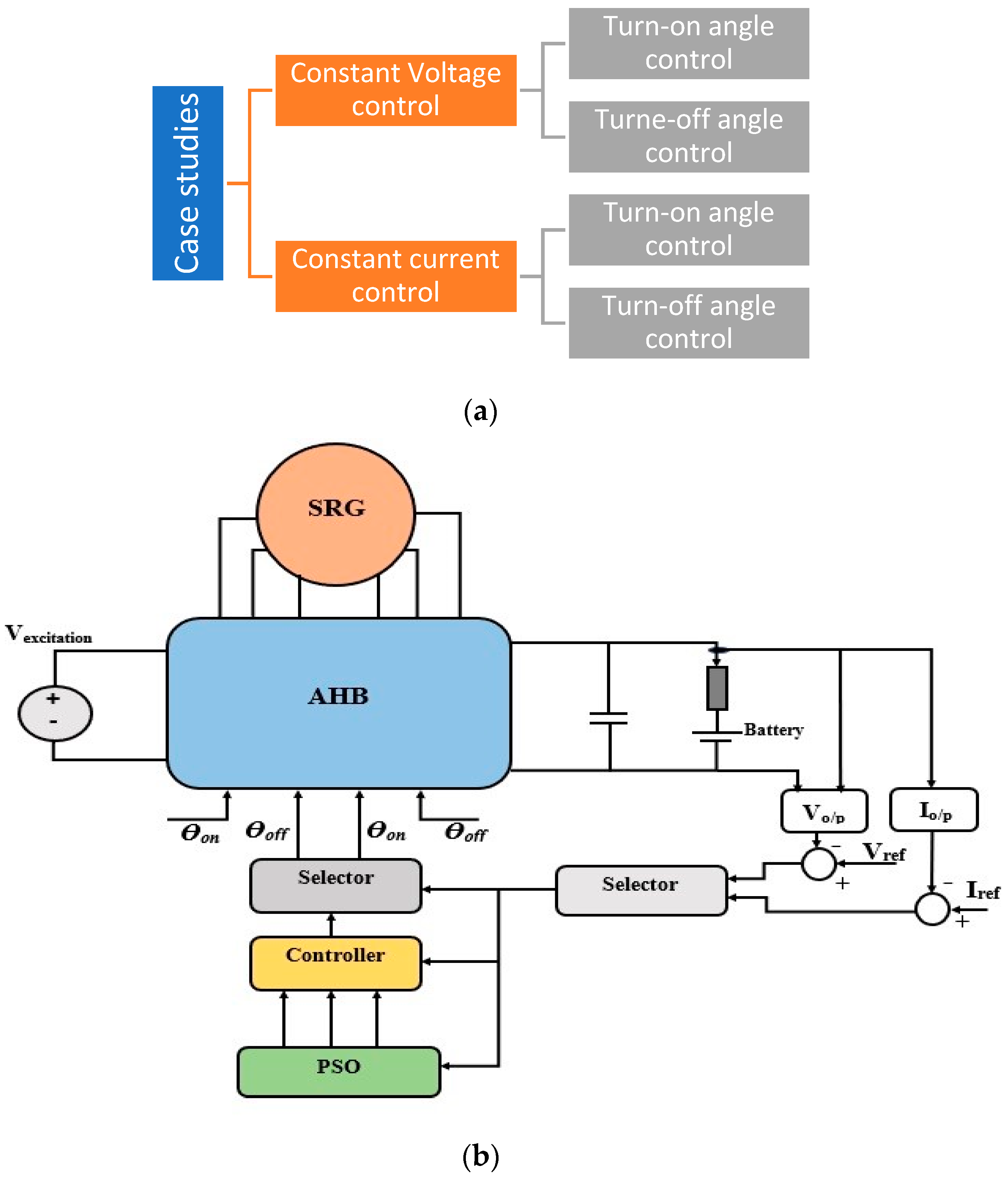
The implemented control system of the SRG model in Simulink® is shown in Figure 3, where the model includes the SRG, position sensor, AHB converter, controller, and load. Simulations and analyses are carried out on the assumption of a constant rated speed. The output of the load is compared with the reference signal. The error signal is the primary input to the PID and fitness function of PSO. PSO optimizes the required PID parameters. The output of the PID could be a turn-on angle or turn-off angle, which depends on the required action. The SRG parameters are listed in Table 1, where the magnetization flux linkage/current curve at different positions is shown in Figure 4.

6. Methodology

The SRG output is generally employed in alternating current conversion systems, such as wind energy systems, starters in aerospace applications, and regenerative braking in transportation systems. The generator output voltage and current must often be controlled to suit these conversion systems. In this research, there are two cases applied for the loads: case (1): Constant output voltage and case (2): Constant output current [48], shown in Figure 5a. In case one, the PID controls the output voltage by the turn-on angle, turn-off angle, or both. In case two, PID is also used to control the current by turn-on or turn-off angles, where its input is the current error. The PSO algorithm is developed to tune the PID parameters. The controller block diagram is shown in Figure 5b. A Simulink model is used to simulate the whole system, including the PID controller, SRG, and load. A MATLAB script is used to carry out the PSO algorithm, which runs the Simulink Model each iteration while updating the PID controller parameters based on the PSO’s output. The integral absolute error (IAE) is employed as the objective function where the PSO block uses the IAE fitness function to optimize the PID settings.

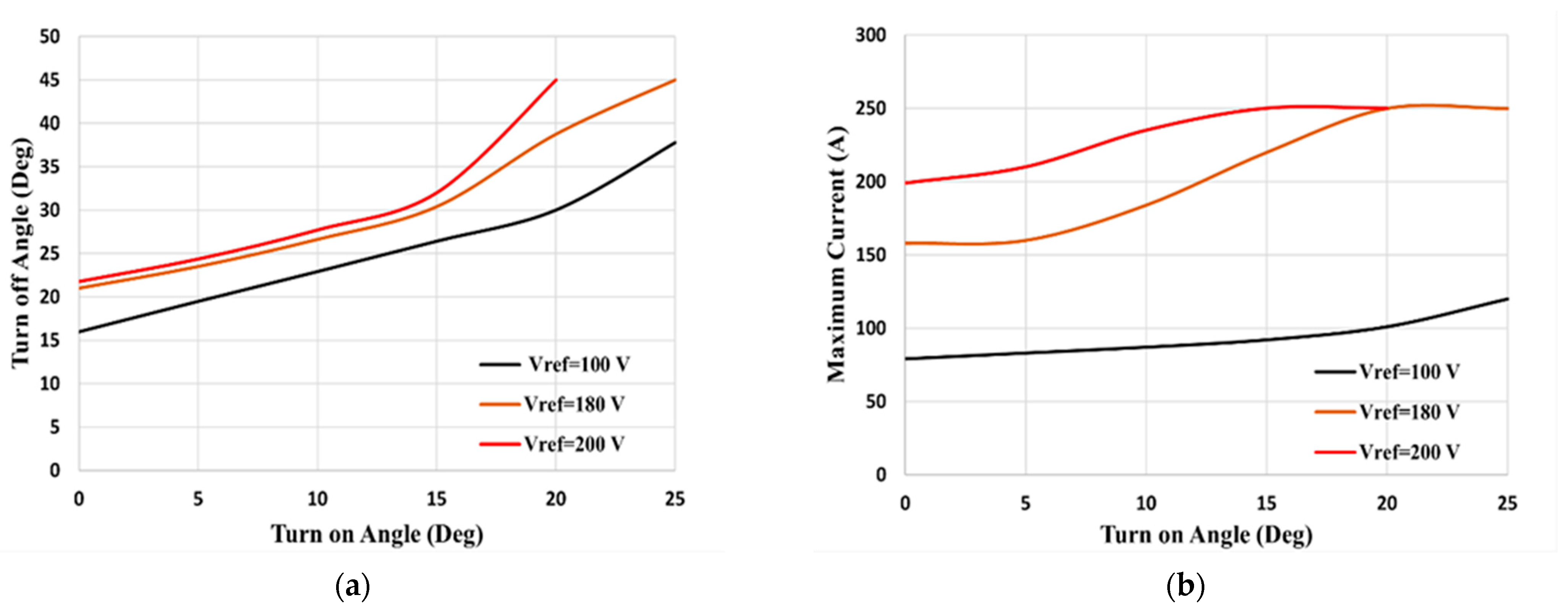
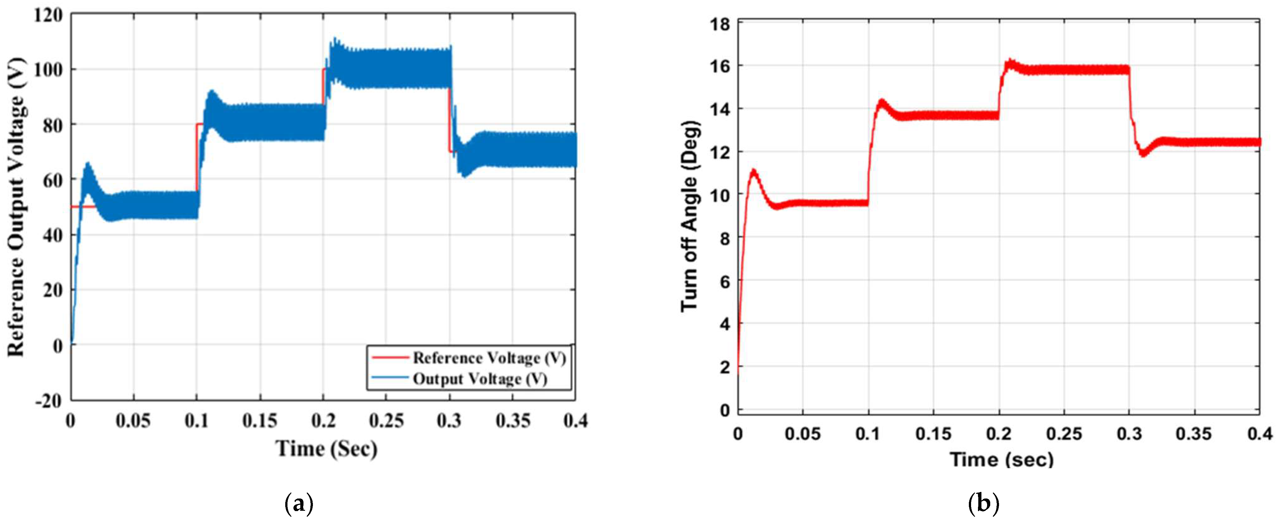
6.1. Case (1): Constant Output Voltage Control

In this case, the voltage control loop is used to maintain a constant output voltage. PSO is used to optimize the PID parameters, generating the required switching angle. In this case, two scenarios are investigated: Controlling the turn-off angle and controlling the turn-on angle.

6.1.1. Turn-Off Angle Control

In this case, the PID is implemented to generate the turn-off angle at a constant turn-on angle. The optimal PID parameters obtained based on multiple runs using the PSO technique for a discrete system at a sampling time of 1 µsec are kp = 0.338, ki = 73.25, and kd = 0.0042. The tuning of the PID controller, in this case, is highlighted in Table 2. The output current responses at two reference voltage values of 100 V and 180 V are shown in Figure 6a,b, respectively. The excitation current for Vref = 180 V has a peak value more than the excitation current for Vref = 100 V because the turn-off angle for the 180 V is more than the turn-off angle for 100 V, while the turn-on angle is fixed at 0°.
The phase current has two intervals: the excitation and the generation intervals. The peak value of the phase current occurs during the generation interval. The different generated turn-off angles at different initial turn-on angles and reference output voltages are shown in Figure 7a. It is shown that increasing the initial turn-on angle affects the generated turn-off angle, where, at an initial turn-on angle of 20°, the turn-off angle is at its maximum and equal to 45° for Vref = 200 V. However, the maximum turn-off angle is 37.5° at an initial turn-on angle of 25° for Vref = 100 V. The peak value of the phase current at different reference output voltages and different initial turn-on angles are illustrated in Figure 7b, which shows that the peak value is constant at a high turn-on angle.
The output voltage response at the turn-off angle control and zero initial turn-on angle, θon = 0.0°, is shown in Figure 8a, which confirms that the output response has a constant steady-state settling time of approximately 0.03 s. The maximum peak overshoot changes from 28% for Vref = 50 V to 10% for Vref = 100 V. The controlled turn-off angle response is simulated in Figure 8b.
The designed controlled system has the advantage of generating different maximum output voltages at different turn-on angles, as shown in Figure 9a, or at different maximum excitation currents, as shown in Figure 9b. The control system can generate a maximum voltage at different fixed turn-on angles and different maximum reference excitation currents. The output response is over-damped and has a steady-state settling time of 0.06 s.

6.1.2. Turn-On Angle Control

PSO is used for tuning the PID parameters, which generates the turn-on angle while the turn-off angle is kept constant. The tuned absolute PID parameters of PID are kp = 0.568, ki = 16.67, and kd = 0.003. Implementing the control system to generate the turn-on angle at different reference output voltages indicates that the time for peak value is different and depends on the reference output voltage, as shown in Figure 10. The turn-off angle is fixed at 45°, while the generated turn-on angle from the PID is responsible for generating the required voltage. The steady-state settling time of the turn-off angle is 0.15 s, while the peak overshoot value is 75% for 100 V output and decreases to 20% for 250 V output.
The generated turn-on angle at different values of turn-off angles and different reference voltages is shown in Figure 11a, where at Vref = 200 V, the minimum turn-off angle is 25°, which gives θon = 5°. Meanwhile, at Vref = 100 v, the minimum turn-off angle is 20°, and the corresponding turn-on angle is 0°. The phase current peak value at different values of turn-off angles and Vref is shown in Figure 11b. The output voltage and the turn-on angles’ response at different reference voltage values are illustrated in Figure 12a,b. The output response has a peak overshoot at the beginning, while there is no peak overshoot after that since the output voltage has an initial value from the previous step. The system can also generate a maximum output voltage at different turn-off angles and different maximum excitation currents, as shown for the turn-off angle control in Figure 13a,b.
Upon comparing the turn-off angle control and turn-on angle control for a constant voltage, the turn-off angle control has a 0.03 s steady state settling time, less than the steady-state settling time for the turn-on angle control, which is 0.15 s. The turn-off angle control for a constant output voltage has less peak overshoot value than the latter. The two techniques have the same steady-state settling time, which is 0.055 s, and the system response is overdamped in the case of generated maximum output voltage.

6.2. Case (2): Constant Current Control

The constant current controller is designed according to the same methodology of constant output voltage. The load, in this case, is a battery in series with a 0.1 Ω resistor, where the load is parallel with a capacitor of 0.1 F. The input signal to the controller is the error difference between the reference current and the actual current. The controller parameters are tuned using PSO. The controller′s output is the turn-on or turn-off angles, depending on which controller is selected first, as shown in Figure 5.

6.2.1. Turn-Off Angle Control

The current control of the turn-off angle is implemented using a PID controller. The PID parameters tuned by PSO are kp = 0.01, ki = 40, kd = 0.0032. The system is tested with the mentioned load of 250 V battery in series with a 0.1 Ω resistor at different current levels, and the setting turn-on angle is 0°. The output response is shown in Figure 14a,b.
The time response of the constant (charging) current is shown in Figure 15 at a fixed 0° turn-on angle. The peak overshoot value is 10% for all cases, occurring at t = 0.025 s. The steady-state settling time is constant for all cases, which is 0.1 s, as is the current response. The battery voltage impacts the turn-off angle and the constant current, where the effect of battery voltage on the turn-off angle is illustrated in Figure 16. The maximum generated current from SRG depends on the battery voltage of the load, where at 250 V, the system can implement 250 A at θoff = 45°, while at 350 V, the maximum current is 200 A at θoff = 45°. The maximum generated current depends on the initial value of the turn-on angle, as shown in Figure 17, where the higher the initial turn-on angle, the less generated current. The system′s response at the maximum generated current is overdamped and has a steady-state settling time of 0.05 s.

6.2.2. Turn-On Angle Control

The control system for a constant current is applied on the turn-on angle control, with a PID controller tuned with PSO. The absolute PID parameters, in this case, are kp = 24.5313, ki = 40.7988, and kd = 0.00064. According to Figure 18a, the constant current has high ripples with less than the maximum allowable current. This is due to the turn-on angle fluctuating between its limits, 0° and 45°. Furthermore, the steady-state settling time is not constant, changing with the reference current. The system is compatible with generating the maximum current when controlling the turn-on angle, as shown in Figure 18b. The maximum generated current depends on the turn-off angle, θoff, and the steady-state settling time is 0.055 s.

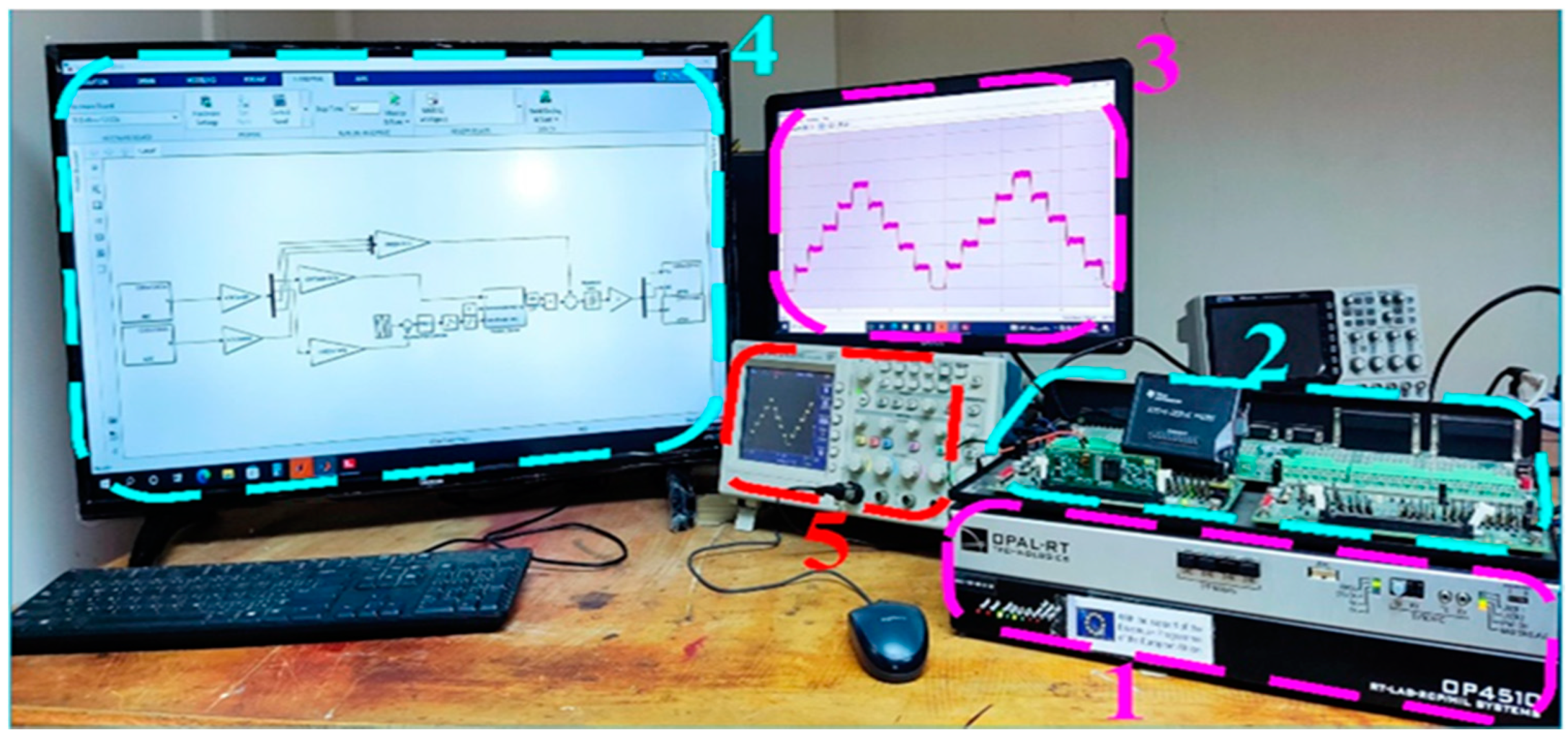
7. Experimental Validation

To experimentally validate the designed system, the Control Hardware-in-the-Loop (CHiL) process is adopted in this section. The hardware platform of the CHiL setup is shown in Figure 19. The hardware configuration of the designed system, consisting of the asymmetric half-bridge (AHB) converter, a Switched Reluctance Generator (SRG), and a battery pack, is emulated on the OPAL-RT platform (OP4510), which operates on four cores based on the Intel Core Xeon processor at 3.5 GHz and RAM 2 × 8 GB. The communication port between the host PC and the OPAL-RT platform is based on Gigabit Ethernet LAN. The system controller is uploaded on a 150 MHz DSP (Digital Signal Processor) control board labeled as (TMS320F28335ZJZA). The DSP represents the closed-loop controller of the designed system. The controller interface (OP8665) is used as a development tool to provide a quick and easy interface for the DSP controller with an OPAL-RT platform without worrying about any interface issues.
The CHiL has been carried out for the constant current PID controller for turn-off and turn-on angle control. The tuned PID parameters from the PSO approach are used in the experimental test. The DSP controller receives signals from the OPAL-RT platform, such as the actual constant current, phase currents, and actual speed, and based on these values, it generates the gating signals to operate the AHB converter on the OPAL-RT platform. The control-hardware-in-the-loop platform is shown in Figure 20.
Output current responses at different reference signals and their corresponding turn-off angles are validated by the OPAL-RT simulator and shown in Figure 21. The response is similar to the Matlab/Simulink response. The maximum current generation is validated and shown in Figure 22a. Dash curves show the Simulink response compared to opal RT simulator solid curves. Validation has been performed for the turn-on control angle, where the output response for a constant current at different reference values is shown as solid curves in Figure 23a, which are compared with Matlab/Simulink response dashed curves. Good validation has been achieved.

8. Conclusions

Extensive efforts have been made to develop reliable and efficient onboard generation systems for electric aircraft. Due to the inherited robustness, Switched Reluctance Machines (SRMs) have attracted attention as a promising candidate for an integrated starter/generator in aerospace applications. This paper has presented two modes of operation: Constant Current (CC) and Constant Voltage (CV). A Particle Swarm Optimization (PSO)-based tuning approach is employed to optimize the controller of a Switched Reluctance Generator (SRG). Both CV and CC control have been achieved separately by controlling the turn-on/off angles. PSO can tune the PID controller easily and efficiently while experiencing good dynamic results. For CV, controlling the turn-off angles is faster with less overshoot than controlling the turn-on angle. Overshoot values of 10% and 75% have been obtained when controlling the turn-off and turn-on angles, respectively. Besides, the steady-state settling time was 0.03 s and 0.15 s when controlling the turn-off and turn-on angles, respectively. The controlling turn-off angle has a 10% peak overshoot for the constant current and 0.1 s for steady-state settling. The response has a high-magnitude ripple for controlling the turn-on angle, and the settling time depends on the reference current. The optimal PID tuning has been carried out for both CV and CC modes. The proposed control system also has the option to generate the maximum current by varying the turn-on angle or turn-off angle. The proposed optimization technique sets the maximum voltage not exceeding the nominal voltage. The control-Hardware-in-the-loop (CHiL) has been used to validate the theoretical findings of the proposed control strategy.

Author Contributions

Conceptualization: M.M.S. and A.S.A.-K.; methodology: M.M.S. and W.E.A.-A.; software: M.M.S. and W.E.A.-A.; validation: M.M.S. and W.E.A.-A.; formal analysis: M.M.S., W.E.A.-A. and A.S.A.-K.; investigation: M.M.S., W.E.A.-A. and A.M.M.; resources: M.M.S., W.E.A.-A. and A.S.A.-K.; data curation: M.M.S., W.E.A.-A. and A.S.A.-K.; writing—original draft preparation: M.M.S., W.E.A.-A., A.S.A.-K. and A.M.M.; writing—review and editing: M.M.S., W.E.A.-A., A.S.A.-K. and A.M.M.; visualization: M.M.S., W.E.A.-A., A.S.A.-K. and A.M.M.; supervision: M.M.S. and A.S.A.-K.; project administration: A.S.A.-K. and A.M.M.; funding acquisition: A.S.A.-K. and A.M.M. All authors have read and agreed to the published version of the manuscript.

Funding

This research was funded by Information Technology Industry Development Agency (ITIDA)’s Information Technology Academia Collaboration (ITAC) collaborative funded project under the category type of advanced research projects (ARP) and grant number ARP2020.R29.7.

Institutional Review Board Statement

Not applicable.

Informed Consent Statement

Not applicable.

Data Availability Statement

Not applicable.

Acknowledgments

The publication of this article was funded by the Qatar National Library. This work was achieved through the financial support of Information Technology Industry Development Agency (ITIDA)’s Information Technology Academia Collaboration (ITAC) collaborative funded project under the category type of advanced research projects (ARP) and grant number ARP2020.R29.7.

Conflicts of Interest

The authors declare no conflict of interest.

References

  1. Bartolo, J.B.; Degano, M.; Espina, J.; Gerada, C. Design and initial testing of a high-speed 45-kW switched reluctance drive for aerospace application. IEEE Trans. Ind. Electron. 2016, 64, 988–997. [Google Scholar] [CrossRef]
  2. Zhao, E.; Song, S.; Ma, Z.; Zhang, X.; Ning, L.; Liu, Y. Design and initial testing of an integrated switched reluctance starter/generator system for unmanned aerial vehicle. CES Trans. Electr. Mach. Syst. 2018, 2, 377–383. [Google Scholar] [CrossRef]
  3. Wang, Y.; Nuzzo, S.; Zhang, H.; Zhao, W.; Gerada, C.; Galea, M. Challenges and opportunities for wound field synchronous generators in future more electric aircraft. IEEE Trans. Transp. Electrif. 2020, 6, 1466–1477. [Google Scholar] [CrossRef]
  4. Chen, Y.; Liu, B. Design and analysis of a five-phase fault-tolerant permanent magnet synchronous motor for aerospace starter-generator system. IEEE Access 2019, 7, 135040–135049. [Google Scholar] [CrossRef]
  5. Nøland, J.K.; Leandro, M.; Suul, J.A.; Molinas, M. High-power machines and starter-generator topologies for more electric aircraft: A technology outlook. IEEE Access 2020, 8, 130104–130123. [Google Scholar] [CrossRef]
  6. Apostolidou, N.; Papanikolaou, N. Active Power Control of Switched Reluctance Generator in More Electric Aircraft. IEEE Trans. Veh. Technol. 2021, 70, 12604–12616. [Google Scholar] [CrossRef]
  7. Guo, H.-J.; Yoshida, J.; Ishihara, T. A Simulation Model and New Speed Control Method of Switched Reluctance Generator for Wind-generator Systems. In Proceedings of the 2021 IEEE Industrial Electronics and Applications Conference (IEACon), Chengdu, China, 1–4 August 2021; pp. 191–194. [Google Scholar]
  8. Cai, S.; Wang, Y.; Chen, H.; Yuan, X.; Yu, L.; Zhang, Z.; Lee, C.H.T. Design and Analysis of a Doubly Salient Wound Field Starter Generator for Cost-Effective Automobile Application. IEEE Trans. Veh. Technol. 2022. [Google Scholar] [CrossRef]
  9. Raj, E.F.I.; Appadurai, M.; Rani, E.F.I.; Jenish, I. Finite-element design and analysis of switched reluctance motor for automobile applications. Multiscale Multidiscip. Modeling Exp. Des. 2022. [Google Scholar] [CrossRef]
  10. Zhu, Y. Modeling of SRM Drive System for EV. In The Key Technologies for Powertrain System of Intelligent Vehicles Based on Switched Reluctance Motors; Springer: Berlin/Heidelberg, Germany, 2022; pp. 1–36. [Google Scholar]
  11. Li, Z.; Yu, X.; Qian, Z.; Wang, X.; Xiao, Y.; Sun, H. Generation Characteristics Analysis of Deflection Type Double Stator Switched Reluctance Generator. IEEE Access 2020, 8, 196175–196186. [Google Scholar] [CrossRef]
  12. Makhad, M.; Zazi, K.; Zazi, M.; Loulijat, A. Adaptive super-twisting terminal sliding mode control and LVRT capability for switched reluctance generator based wind energy conversion system. Int. J. Electr. Power Energy Syst. 2022, 141, 108142. [Google Scholar] [CrossRef]
  13. Mapa, S.; Bhuvaneswari, G. Suitable Choice of Capacitor for a Self-excited Switched Reluctance Generator Driven by a Roof-Top Wind Turbine at Varying Wind Speeds. Trans. Indian Natl. Acad. Eng. 2022, 7, 259–267. [Google Scholar] [CrossRef]
  14. Touati, Z.; Pereira, M.; Araújo, R.E.; Khedher, A. Improvement of Steady State Performance of Voltage Control in Switched Reluctance Generator: Experimental Validation. Machines 2022, 10, 103. [Google Scholar] [CrossRef]
  15. Ahmad, S.S.; Narayanan, G. Modeling of single-pulse operated switched reluctance generator and its verification. IEEE Trans. Ind. Appl. 2020, 56, 4966–4976. [Google Scholar] [CrossRef]
  16. Ichinokura, O.; Kikuchi, T.; Nakamura, K.; Watanabe, T.; Guo, H.-J. Dynamic simulation model of switched reluctance generator. IEEE Trans. Magn. 2003, 39, 3253–3255. [Google Scholar] [CrossRef]
  17. Omaç, Z.; Cevahir, C. Control of switched reluctance generator in wind power system application for variable speeds. Ain Shams Eng. J. 2021, 12, 2665–2672. [Google Scholar] [CrossRef]
  18. Arifin, A.; Al-Bahadly, I.; Mukhopadhyay, S.C. State of the art of switched reluctance generator. Sci. Res. 2012, 4, 447–458. [Google Scholar] [CrossRef] [Green Version]
  19. Wang, K.; Zhou, B.; Zhou, X.; Jiang, S.; Wei, J. The output voltage control strategy for DSEG with controlled rectification based on conduction angle estimation. IEEE Trans. Ind. Electron. 2019, 67, 3350–3360. [Google Scholar] [CrossRef]
  20. Zhu, Y.; Wu, H.; Zhang, J. Regenerative braking control strategy for electric vehicles based on optimization of switched reluctance generator drive system. IEEE Access 2020, 8, 76671–76682. [Google Scholar] [CrossRef]
  21. Catata, E.O.H.; Neto, P.J.D.S.; de Paula, M.V.; Silveira, J.P.C.; Barros, T.A.D.S.; Filho, E.R. In-Loop Adaptive Filters to Improve the Power Quality of Switched Reluctance Generator in WECS. IEEE Access 2021, 10, 2941–2951. [Google Scholar] [CrossRef]
  22. Rahmanian, E.; Akbari, H.; Sheisi, G.H. Maximum power point tracking in grid connected wind plant by using intelligent controller and switched reluctance generator. IEEE Trans. Sustain. Energy 2017, 8, 1313–1320. [Google Scholar] [CrossRef]
  23. Verma, A.; Ahmad, S.S.; Narayanan, G. Optimal Switching Angles for Single-Pulse-Operated Switched Reluctance Generator. In Proceedings of the 2021 National Power Electronics Conference (NPEC), Bhubaneswar, India, 15–17 December 2021; pp. 1–6. [Google Scholar]
  24. Zhi, X.; Xiangjun, D.; Lei, L. MPPT for wind power system with switched reluctance generator. In Proceedings of the 2018 13th IEEE Conference on Industrial Electronics and Applications (ICIEA), Wuhan, China, 31 May 2018–2 June 2018; pp. 1420–1424. [Google Scholar]
  25. Sun, N.; Choi, D.; Li, J.; Cho, Y. The angle control of switched reluctance generator for maximum output power. In Proceedings of the 2012 Sixth International Conference on Electromagnetic Field Problems and Applications, Dalian, China, 19–21 June 2012; pp. 1–4. [Google Scholar]
  26. Hajiabadi, H.; Farshad, M.; Nejad, M.A.S. Maximum power extraction for switched reluctance generator wind turbine using optimal firing angles control. In Proceedings of the 2019 Iranian Conference on Renewable Energy & Distributed Generation (ICREDG), Tehran, Iran, 11–12 June 2019; pp. 1–7. [Google Scholar]
  27. Viajante, G.P.; Sanguino, T.d.M. Design and implementation of a fuzzy control system applied to a 6 × 4 srg. IEEE Trans. Ind. Appl. 2020, 57, 528–536. [Google Scholar] [CrossRef]
  28. Domínguez-Navarro, J.A.; Artal-Sevil, J.; Pascual, H.; Bernal-Agustín, J.L. Fuzzy-logic strategy control for switched reluctance machine. In Proceedings of the 2018 Thirteenth International Conference on Ecological Vehicles and Renewable Energies (EVER), Monte Carlo, Monaco, 10–12 April 2018; pp. 1–5. [Google Scholar]
  29. Park, K.; Chen, Z. Self-tuning fuzzy logic control of a switched reluctance generator for wind energy applications. In Proceedings of the 2012 3rd IEEE International Symposium on Power Electronics for Distributed Generation Systems (PEDG), Aalborg, Denmark, 25–28 June 2012; pp. 357–363. [Google Scholar]
  30. Li, J.; Li, Y.; Wang, Y. Fuzzy Inference NSGA-III Algorithm-Based Multi-Objective Optimization for Switched Reluctance Generator. IEEE Trans. Energy Convers. 2021, 36, 3578–3581. [Google Scholar] [CrossRef]
  31. Chen, H.; Nie, R.; Gu, J.; Yan, S.; Zhao, R. Efficiency optimization strategy for switched reluctance generator system with position sensorless control. IEEE/ASME Trans. Mechatron. 2020, 26, 469–479. [Google Scholar] [CrossRef]
  32. Chen, H.; Xu, D.; Deng, X. Control for power converter of small-scale switched reluctance wind power generator. IEEE Trans. Ind. Electron. 2020, 68, 3148–3158. [Google Scholar] [CrossRef]
  33. Kennedy, J.; Eberhart, R. Particle swarm optimization. In Proceedings of the ICNN’95-international conference on neural networks, Perth, WA, Australia, 27 November–1 December 1995; Volume 4, pp. 1942–1948. [Google Scholar]
  34. Üstün, O.; Önder, M.; Sefa, İ. Identification of mechanical parameters for the switched reluctance motor. In Proceedings of the 2018 2nd International Symposium on Multidisciplinary Studies and Innovative Technologies (ISMSIT), Ankara, Turkey, 19–21 October 2018; pp. 1–7. [Google Scholar]
  35. Scalcon, F.P.; Vieira, R.P.; Gründling, H.A. PSO-Based Fast Mechanical Parameters Estimation of Switched Reluctance Motor Drives. J. Control. Autom. Electr. Syst. 2022, 1–8. [Google Scholar] [CrossRef]
  36. Mapa, S.; Gurumoorthy, B. Maximum power extraction from a switched reluctance generator based wind power generating system using optimization techniques. Eng. Rep. 2022, 4, e12457. [Google Scholar] [CrossRef]
  37. Mahfoud, S.; Derouich, A.; el Ouanjli, N.; Quynh, N.V.; Mossa, M.A. A New Hybrid Ant Colony Optimization Based PID of the Direct Torque Control for a Doubly Fed Induction Motor. World Electr. Veh. J. 2022, 13, 78. [Google Scholar] [CrossRef]
  38. Ghith, E.S.; Tolba, F.A.A. Real-Time Implementation of Tuning PID Controller Based on Whale Optimization Algorithm for Micro-robotics System. In Proceedings of the 2022 14th International Conference on Computer and Automation Engineering (ICCAE), Brisbane, Australia, 25–27 March 2022; pp. 103–109. [Google Scholar]
  39. Kumar, N.K.; Gopi, R.S.; Kuppusamy, R.; Nikolovski, S.; Teekaraman, Y.; Vairavasundaram, I.; Venkateswarulu, S. Fuzzy Logic-Based Load Frequency Control in an Island Hybrid Power System Model Using Artificial Bee Colony Optimization. Energies 2022, 15, 2199. [Google Scholar] [CrossRef]
  40. Shan, J.; Chu, S.-C.; Weng, S.-W.; Pan, J.-S.; Jiang, S.-J.; Zheng, S.-G. A parallel compact firefly algorithm for the control of variable pitch wind turbine. Eng. Appl. Artif. Intell. 2022, 111, 104787. [Google Scholar] [CrossRef]
  41. Yalçin, O.; Canli, A.; Yilmaz, A.R.; Erkmen, B. Robust Tuning of PID Controller Using Differential Evolution Algorithm Based on FPGA. In Proceedings of the 2022 9th International Conference on Electrical and Electronics Engineering (ICEEE), Alanya, Turkey, 29–31 March 2022; pp. 180–184. [Google Scholar]
  42. Sundararaju, N.; Vinayagam, A.; Veerasamy, V.; Subramaniam, G. A Chaotic Search-Based Hybrid Optimization Technique for Automatic Load Frequency Control of a Renewable Energy Integrated Power System. Sustainability 2022, 14, 5668. [Google Scholar] [CrossRef]
  43. Saremi, S.; Mirjalili, S.; Lewis, A. Grasshopper optimisation algorithm: Theory and application. Adv. Eng. Softw. 2017, 105, 30–47. [Google Scholar] [CrossRef] [Green Version]
  44. Sun, L.; Vansompel, H.; Zhang, Z.; Ibrahim, M.N.; Sergeant, P. Comparative Study of Switched Reluctance Generators with Separate Field Current and Circulating Current Excitations. IEEE Trans. Energy Convers. 2021, 37, 1124–1133. [Google Scholar] [CrossRef]
  45. Scalcon, F.P.; Vieira, R.P.; Gründling, H.A. PSO-Based Performance Optimization Procedure for Current-Controlled Switched Reluctance Generators in Wind Power Applications. In Proceedings of the IECON 2021–47th Annual Conference of the IEEE Industrial Electronics Society, Toronto, ON, Canada, 13–16 October 2021; pp. 1–6. [Google Scholar]
  46. Araujo, W.R.H.; Reis, M.R.C.; Wainer, G.A.; Calixto, W.P. Efficiency Enhancement of Switched Reluctance Generator Employing Optimized Control Associated with Tracking Technique. Energies 2021, 14, 8388. [Google Scholar] [CrossRef]
  47. Maghfiroh, H.; Saputro, J.; Hermanu, C.; Ibrahim, M.; Sujono, A. Performance Evaluation of Different Objective Function in PID Tuned by PSO in DC-Motor Speed Control. In IOP Conference Series: Materials Science and Engineering; IOP Publishing: Philadelphia, PA, USA, 2021; Volume 1096, p. 012061. [Google Scholar]
  48. Kawata, N.; Chiba, A. Design of switched reluctance generator for competitive energy efficiency in the latest hybrid electric vehicle. In Proceedings of the 2018 IEEE Energy Conversion Congress and Exposition (ECCE), Portland, OR, USA, 23–27 September 2018; pp. 6461–6467. [Google Scholar]
  49. Qi, Z.; Shi, Q.; Zhang, H. Tuning of Digital PID Controllers Using Particle Swarm Optimization Algorithm for a CAN-Based DC Motor Subject to Stochastic Delays. IEEE Trans. Ind. Electron. 2020, 67, 5637–5646. [Google Scholar] [CrossRef]
  50. Verma, B.; Padhy, P.K. Robust Fine Tuning of Optimal PID Controller with Guaranteed Robustness. IEEE Trans. Ind. Electron. 2020, 67, 4911–4920. [Google Scholar] [CrossRef]
  51. Gaing, Z.-W. A particle swarm optimization approach for optimum design of PID controller in AVR system. IEEE Trans. Energy Convers. 2004, 9, 384–391. [Google Scholar] [CrossRef] [Green Version]
Figure 1. Three-phase 6/4 SRM layout’s construction.
Applsci 12 07583 g001
Figure 2. SRM inductance profile.
Applsci 12 07583 g002
Figure 3. Block diagram of the proposed control strategy.
Applsci 12 07583 g003
Figure 4. Magnetization curve for SRG model.
Applsci 12 07583 g004
Figure 5. (a) Addressed case studies and (b) the SRG system block diagram.
Applsci 12 07583 g005
Figure 6. Current response at (a) Vref = 100 V, (b) Vref = 180 V.
Applsci 12 07583 g006
Figure 7. The effect of the initial turn-on angle on (a) the generated turn-off angle and (b) the maximum generated current at different reference output voltages.
Applsci 12 07583 g007
Figure 8. The transient response of turn-off angle control, (a) different reference output voltage (v); (b) the corresponding generated turn-off angle in deg.
Applsci 12 07583 g008
Figure 9. Maximum generated output voltage in volt at (a) different initial turn-on angle in deg, (b) different reference maximum input current.
Applsci 12 07583 g009
Figure 10. Output voltage response at turn-on angle control (at turn-off = 0.0).
Applsci 12 07583 g010
Figure 11. The effect of the initial turn-off angle on (a) the generated turn-on angle and (b) the maximum generated current at different reference output voltages.
Applsci 12 07583 g011
Figure 12. The transient response of turn-on angle control, (a) different reference output voltage (v), (b) the corresponding generated turn-on angle in deg.
Applsci 12 07583 g012
Figure 13. Maximum generated output voltage in volts at (a) different initial turn-off angles in deg, (b) different reference maximum input current.
Applsci 12 07583 g013
Figure 14. Turn-off angle control on constant (charging) current response (Vbattery = 250 V, θon = 0°), (a) the constant current at different reference values and (b) the corresponding turn-off angle.
Applsci 12 07583 g014
Figure 15. Output current response at (Vbattery = 250 V, θon = 0°).
Applsci 12 07583 g015
Figure 16. The generated turn-off angle control with reference current at different battery voltage.
Applsci 12 07583 g016
Figure 17. Maximum allowable current at different θon angles.
Applsci 12 07583 g017
Figure 18. Constant (charging) current response for turn-on angle control, (a) transient current at different reference currents, and (b) maximum generated current at different turn-off angles.
Applsci 12 07583 g018
Figure 19. Block diagram of the (ChiL) process.
Applsci 12 07583 g019
Figure 20. Control-hardware-in-the-loop platform: (1) Opal-RT real-time simulator, (2) OP8665 controller interface, (3) opal interface and monitoring, (4) DSP interface, (5) Oscilloscope.
Applsci 12 07583 g020
Figure 21. Opal-RT real-time simulator turn-off angle control on constant current response (Vbattery = 250 V, θon = 0°), (a) the constant current at different reference values, (b) the corresponding turn-off angle.
Applsci 12 07583 g021
Figure 22. Opal-RT real-time simulator response for turn-off angle control; (a) effect of initial turn-on angle on maximum current (solid traces for experimental results and dashed traces for simulation), (b) effect of battery voltage on turn-off angle at different reference currents.
Applsci 12 07583 g022
Figure 23. Opal-RT real-time simulator response for turn-on angle, (a) constant current response at different references currents, (b) effect of turn-off angle on maximum constant current (solid line is experimental, and dashed line is simulation).
Applsci 12 07583 g023
Table 1. Simulated SRG parameters.
ParameterValueUnit
number of phases3
number of stator poles6
number of rotor poles 4
stator resistance 0.05
machine inertia 0.05 N m s2/rad
friction 0.02N m s/rad
unaligned Inductance 0.67 × 10⁻³H
aligned Inductance 23.6 × 10⁻³H
maximum Current 450A
maximum Flux Linkage 0.486V s
rated Speed 3000 RPM
Table 2. Tuning of PID controller in turn off.
kpkikd
PS10.38297672.977170.004077
PS20.38845574.306450.004164
PS30.38808873.307990.004163
PS41.405067176.19520.004016
PS50.047432100.05670.003584
PS60.39009373.223600.004168
PS70.70141797.901110.004426
PS80.34126847.790830.004200
PS90.409198102.93440.003757
PS100.33880073.254630.004200
Publisher’s Note: MDPI stays neutral with regard to jurisdictional claims in published maps and institutional affiliations.

