
Tug-of-War in the Selection of Materials for Battery Technologies


1
Electrical and Electronic Department, Universidad de los Andes, Calle 19A No. 1-82, Bogota 111711, Colombia
2
Grupo de Nanoestructuras y Fisica Aplicada (NANOUPAR), Universidad Nacional de Colombia Sede De La Paz, Km 9 Via Valledupar, La Paz 202010, Colombia
*
Author to whom correspondence should be addressed.
Batteries 2022, 8(9), 105; https://doi.org/10.3390/batteries8090105
Submission received: 23 July 2022
/
Revised: 15 August 2022
/
Accepted: 18 August 2022
/
Published: 24 August 2022
(This article belongs to the Topic Materials for Energy Harvesting and Storage)
Abstract
:Batteries are the heart and the bottleneck of portable electronic systems. They power electronics and determine the system run time, with the size and volume determining factors in their design and implementation. Understanding the material properties of the battery components—anode, cathode, electrolyte, and separator—and their interaction is necessary to establish selection criteria based on their correlations with the battery metrics: capacity, current density, and cycle life. This review studies material used in the four battery components from the perspective and the impact of seven ions (Li, Na, K, Zn, Ca, Mg, and Al), employed in commercial and research batteries. In addition, critical factors of sustainability of the supply chains—geographical raw materials origins vs. battery manufacturing companies and material properties (Young’s modulus vs. electric conductivity)—are mapped. These are key aspects toward identifying the supply chain vulnerabilities and gaps for batteries. In addition, two battery applications, smartphones and electric vehicles, in light of challenges in the current research, commercial fronts, and technical prospects, are discussed. Bringing the next generation of batteries necessitates a transition from advances in material to addressing the technical challenges, which the review has powered.
1. Introduction
Batteries are one of the most widely commercialized energy storage systems and have been extensively used for powering portable electronic devices [1,2,3,4]. This widespread use of batteries has transformed our daily lives and is leading the future of multifunctional, interconnected, and energy-independent devices [5]. For example, the Internet of Things (IoT) integrates devices that work not just as sensors, but also as transmitters of the sensing signals, and these devices require batteries with a higher level of performance (higher energy density and long cycle life) to power their operations [5,6]. To satisfy the requirements of these applications (size, portability, and flexibility), rapid advances have been made toward exploring new materials. Different materials have been used for the battery components: cathode [7,8,9], anode [10,11,12], electrolyte [13,14,15], and separators [16,17]. Any decision about the next generation of batteries will have to move beyond trial and error toward a material-based selection. This decision has to leverage the best material performance vs. availability.
Historically, the evolution of batteries has been a slow process that combines not only intelligence but also serendipity to integrate the suitable component materials that would enable the development of practical batteries with acceptable parameters: voltage, capacity, and energy density [18]. In 1800, Alessandro Volta discovered that particular liquids allow for the flow of electrical power if they are used as a conductor. Joining silver (Ag) and zinc (Zn) electrodes in an electrolyte, Volta realized that the voltage generated in the terminals could be controlled with stacked voltaic cells [19,20]. Then, in 1802, William Cruickshank started the mass production of electric batteries (non-rechargeable), changing the Ag electrode to a copper (Cu) one. It was not until 1859 that the rechargeable battery was invented by Gaston Plante, employing an alternative technology that integrates lead (Pb) electrodes and acid as the electrolyte. Afterward, the nickel–cadmium (NiCd) battery was introduced in 1899. The use of Ni and Cd electrodes allowed for a higher energy density than Pb-acid batteries in a smaller and lighter size. The development of NiCd batteries made the use of portable devices possible. Due to safety issues, Cd was replaced with metal–hydride and, quickly, NiMH batteries became the most widely used kind of batteries in 1947 [21]. The 1960s saw the beginnings of lithium (Li) based batteries which had a higher energy density. However, it was only 30 years later that the main difficulties with Li batteries, such as volume expansion, dendrite growth, and side reactions, were acceptably resolved, resulting in the introduction of lithium-ion batteries (LIBs). At that time, these batteries reported the highest energy density by joining a graphite anode and a LiCoO cathode [22]. Since then, LIB components have been optimized to increase the energy density.
To manufacture batteries with high energy density, several materials have been used. Metals are the most promising materials for anodes because they can deliver high capacity density. Li is the most studied metal due to its high capacity density and low potential. The concern about using Li is its scarcity. It is estimated that the current Li production cannot meet the demand in the coming decade unless the sustainability of extraction methods could be improved and a recycling process could be effectively developed [23,24]. To alleviate concerns about Li availability, alternative metal anodes have been studied. These alternatives include sodium (Na), potassium (K), zinc (Zn), calcium (Ca), magnesium (Mg), and aluminum (Al), with their respective working ions [15]. Today, the use of metal anodes in practical batteries is still limited by the dendrite growth [22], the large ionic size [25], low-voltage window, and irreversibility [26]. For cathodes, sulfur (S) [7] and oxygen (O) [27] have been studied as an alternative to traditional transition metal oxide electrodes. For electrolytes, switching from carbonates and ionic liquids to polymers and ceramic solid-state is a trend that can address safety concerns and offer additional mechanical properties while fulfilling the functions of separators.
To demonstrate the evolution of batteries, Figure 1 presents a bibliometric review of published articles from 1990 to 2021 and compares seven battery types according to the working ions Li, Na, K, Zn, Ca, Mg, and Al. In Figure 1, the difference between estimations and the actual number of publications demonstrates the drop off in research in 2020 and 2021, which could be the result of the pandemic [28].
The pie graphs show that Li-based batteries are the most studied (% of the publications), followed by Na-based batteries (% ) and Zn-based batteries (% ). This is because LIBs have shown successful practical application in portable electronic devices and electric vehicles, and most research moved to lithium systems for developing efficient battery component materials to achieve higher performance [29]. Current battery technologies based on Li include LIB ( kg−1) [4], Li-Sulfur ( Li–S 2600 kg−1) [30,31], Li-Oxygen (Li–O 3500 kg−1) [32,33], and Li-air [34] technologies.
Na-based batteries have also been widely explored since Li and Na electrode materials have similar structures, and most of the electrode materials discovered for Li batteries have been tested on Na cells [35]. Na-based batteries include Na-ion (SIB) [36], Na-sulfur ( kg−1) [37], Na-selenium (Na-Se), and Na-oxygen (Na–O) [27]. In the case of Zn-based batteries, Zn-air has been successfully commercialized as non-rechargeable cells, and used in applications such as hearing aids. Today, interest is focused on the possibility of switching to rechargeable cells [38]. Zinc-based batteries include Zn-air ( 1086 kg−1) and Zn-ion (ZIB) technology.
In contrast, the published articles for K, Ca, Mg, and Al represent only % of the total publications. This could be the result of drawbacks that have not yet been resolved and that limit the development of practical batteries. However, there seems to be a growing interest in these new technologies considering that the percentage of publications has increased from 2020 to 2021. Some examples of these technologies are K-ion (KIB) [25], K-S ( 1023 kg−1) [39], Ca-ion (CIB), Mg-ion (MIB), Mg-S, Mg-air [40], Al-ion (AIB) and Al-air batteries.
Previous reviews have addressed battery progress from three perspectives: (1) studying the state of the art of a specific battery part, such as anodes [41], cathodes [42], electrolytes [15], and separators [17], (2) focusing on only one battery technology [39], and (3) comparing two or three battery technologies [43]. The main contribution of this review is that we analyze the materials for anodes, cathodes, electrolytes, and separators from seven battery types according to the working ion: Li, Na, K, Zn, Ca, Mg, and Al. For these materials, we studied the parameters (voltage, capacity, current rate, Coulombic efficiency, retention, and cycle number) that determine the battery performance (capacity, energy, and lifetime). This review is organized as follows. Battery specifications are described in Section 2, which includes electrical parameters, battery types according to their mechanical and chemical characteristics, and sustainability factors. Anodes and cathode types are described widely in Section 3 and Section 4, respectively. Electrolytes and separators are explained in Section 5. Finally, we added a section on battery applications, and we concluded with the perspectives of materials for manufacturing electrodes, electrolytes, and separators.
2. Battery Specifications
A battery is an electrochemical energy storage system that converts chemical energy into electrical energy. A battery consists of several electrochemical cells which integrate four main components as shown in Figure 2: (1) the anode or negative electrode; (2) the cathode or positive electrode; (3) the electrolyte that is the medium between the anode and cathode; and (4) the separator, a membrane to physically separate the anode and the cathode electrically. During discharge, ions move from the anode to the cathode through the electrolyte, and electrons flow from the anode to cathode through an external circuit. During charge, ions come back to the anode through the electrolyte while an external source forces the electrons to move from the cathode to the anode side. Although Li is the most used, other working ions include Na, K, Zn, Ca, Mg, and Al. It is crucial to keep in mind that the chemistry inside a battery changes according to the working ion used. Therefore, the anodes and cathodes used for Li-based batteries cannot be frequently used in the other battery types.
Figure 2 also presents a general classification of materials used for anodes, cathodes, and electrolytes, and their internal structures according to the operating mechanism. These mechanisms are explained in Section 3, Section 4 and Section 5, respectively. This section provides the terminology, including electrical parameters, types, and sustainability factors, of batteries and their component materials.
2.1. Electrical Parameters
Electrical characteristics are technical operating parameters to assess battery performance. These parameters are used to describe the present condition of a battery, such as state of charge, depth of charge, internal resistance, terminal voltage, and open-circuit voltage, or to compare manufacture specifications, such as capacity, C-rate, nominal voltage, cut-off voltage, energy, power, and cycle life. Electrical parameters are usually presented in graphics to compare different technologies. For example, the Ragone plot is a typical graph that contrasts the energy and power density of different battery chemistries.
The battery parameters used in this review are defined in this section. The first parameter is the capacity. Capacity is the charge that a battery can store and is established by the mass of the active material. Capacity refers to the total amount of Amp-hours (Ah) available when the battery is discharged. To determine the capacity, it is necessary to multiply the discharge current by the discharge time. The second relevant parameter is C-rate, which is defined as the battery discharge current according to battery capacity. C-rate gives a measure of the rate at which a battery is discharged relative to its maximum capacity. For example, 1C rate means that the battery with a capacity of 1000 could be discharged in 1 at a current of 1000 . For this battery, 5 C rate means that the battery is discharged in 12 min at 5000 , and a C/2 rate means that the battery is discharged in 2 at 500 . In addition, there is an inversely proportional relationship between the capacity and the C-rate, which means that battery capacity decreases when the C-rate increases.
Another battery parameter is voltage, which indicates the difference between cathode and anode potential. To achieve a high voltage, an ideal cathode should have a high potential, while an ideal anode should have a low potential. Usually, the reported voltage of the battery is called nominal voltage, and the minimum acceptable operational voltage, which defines the “empty” state of the battery, is the cut-off voltage. Power is how many watts are stored, which is calculated by multiplying the voltage by the current density. Commonly, power is given per unit mass, specific power ( kg−1), or per unit volume, power density (W L−1). Power density determines the battery size needed to achieve a given performance purpose. Energy is the watt hour that a battery supply at a certain C-rate. Energy is also expressed per unit mass as specific energy ( kg−1) or per unit volume as energy density (W h L−1) [44]. Cycle life is the number of discharge–charge cycles the battery performs while maintaining specific performance criteria.
State of charge (SOC%) describes the instant battery capacity as a percentage of maximum capacity. Depth of discharge (DOD%) expresses the battery capacity that has been discharged of maximum capacity as a percentage. Internal resistance is the resistance inside the battery that varies for charging and discharging. If the internal resistance increases, the battery efficiency and thermal stability are reduced since the charging energy is converted into heat.
Table 1 summarizes the standard electrical parameters that are used to evaluate the performance of batteries and their components. The symbol, the unit, and a brief definition of each parameter are included.
2.2. Battery Types
Batteries can be classified in three different ways according to the chemical interaction of their components during the redox reaction. First, batteries are rechargeable if the redox reaction is reversible, and non-rechargeable if the reaction occurs just once. Second, batteries can be categorized as monovalent or multivalent according to the charge carrier ions. Finally, batteries can be organic or inorganic, depending on the material type used for manufacturing.
- Rechargeable or Non-Rechargeable
Inside a battery, chemical energy is converted into electrical energy through a redox reaction. The anode is oxidized and delivers electrons to the cathode that is reduced. The electrochemical reaction is irreversible in non-rechargeable systems, also known as primary batteries. In consequence, the battery must be replaced after the discharge. In a rechargeable battery, also called a secondary battery, the chemical reaction is reversible. As a result, the battery can be charged from an external source and restored to the original chemical conditions within the cell [21,46].
- Monovalent and Multivalent
A monovalent battery is a mature technology in which each ion generates one electron in the external circuit. On the other hand, in a multivalent battery, one ion generates two or three electrons in the external circuit, depending on the charge carrier ions. Consequently, in multivalent batteries, a higher current density is generated, and also the capacity could be doubled or tripled [47,48]. Common monovalent ions are Li, Na, and K, and the most researched multivalent ions are Zn, Ca, Mg, and Al.
Multivalent batteries are in the research stage, and technical challenges, such as instability and short cycle life, must be addressed to manufacture commercial applications successfully. Instability and short cycle life could be ascribed to volume expansion, interface degradation and active losing. For example, the electrode volume expansion, generated by the extra electrons, causes electrode breaks. In addition, Al and Ca electrodes reversibility was recently demonstrated [49,50], and it is still necessary to improve stability and the cycle life of these systems [47]. Finally, the cell assembly of multivalent batteries requires strong atmosphere control procedures to avoid contaminants such as water or oxygen, which could generate the formation of the passive film in an anode electrode [47].
- Organic and Inorganic
Commercial batteries are built with inorganic materials since they have a higher specific capacity than organic materials. These inorganic materials include heavy metals, such as Co, Pb, and Ni, and alkaline metals, such as Li. The concern about using these materials is because of the negative environmental impact from their toxicity and danger to human safety. Conversely, organic batteries are built using organic battery materials composed of C, H, O, N, or S. Some of the most common organic materials are based on metal-organic frameworks (MOFs) and covalent organic frameworks (COFs), that are crystalline porous materials with large surface areas, well-defined crystalline structures and highly ordered pores [51]. Interest in these organic materials surged due to their low cost and high availability. They are studied as active material in electrodes as well as electrolytes and separators [52]. Organic batteries exhibit a high rate of performance and a longer cycle life than inorganic batteries. This is to due to the fact that the redox process in organic batteries is fast, and it does not imply changes in the layer structure of intercalation materials used in inorganic batteries [52,53,54,55]. However, the low conductivity limits their practical application, and, therefore, it is necessary to continue researching solutions for this challenge [51].
- Flow Batteries
Flow batteries are an energy storage system based on electrochemical technology in which at least one electrode should be a solution. The difference between a traditional and flow battery is that the charge-discharge process occurs directly in a conventional battery since there is no spatial parting between the energy conversion unit and active material. On the other hand, in a flow battery, the energy conversion unit and active material are physically separated from each other [2]. The flow battery promises to be an alternative for large battery systems by pumping fluids from external tanks through a membrane that resembles a battery. This operation mechanism limits their application in wearable and portable devices, generating issues due to corrosion, high cost, and adverse environmental and safety impact [56].
Batteries can also be rigid or flexible according to the fabrication processes, material mechanical properties, and internal configuration. Rigid batteries have hard packing, and they are manufactured based on the slurry-casting method and also by dry electrode technology [57]. In contrast, flexible batteries (FB) are based on multilayers of a separator sandwiched by two electrodes, with a versatile packing [58]. The advantages and disadvantages of rigid and flexible batteries are described in the following paragraphs.
- Rigid Batteries or Flexible Batteries
Rigid batteries are the largest commercial battery market, which provides a wide range of capacities. The rigid packages offer mechanical stability and protection to the internal components. Although today there are a large number of battery sizes and shapes, rigid batteries can be classified into four types of shape: coin, cylindrical, prismatic, and pouch [1] (Figure 3).
Coin cells, also known as button cells, are small disk batteries that consist of a single cell encased in stainless steel, as presented in Figure 3. Typically, these cells have a diameter of 5 mm to 25 mm and a height of 1 mm to 6 mm. Voltage in coin cells is between and 3 , and the capacity is between 1 and 2000 . Applications of coin cells include powering small portable electronic devices, such as wristwatches and hearing aids. Therefore, these cells should exhibit a long service life, at least one year, since they are frequently non-rechargeable cells. Commercial coin cells include chemistries such as Lithium-manganese dioxide, and Zinc-air [59].
Cylindrical cells consist of layered electrodes and separators rolled and encased in a metal casing as shown in Figure 3. These cells have different sizes, varying in the range of 8 to 20 in diameter and 25 to 70 in height. Standard size references are A, AA, or AAA for alkaline and Ni-metal–hydride, which have a voltage of and a capacity between 700 to 3000 . For LIB, the most common size is 18,650, which has a voltage of and a capacity of 3900 . Usually, cylindrical cells are used in portable devices, power tools, medical instruments, laptops, e-bikes, and electric vehicles due to their high specific energy, good mechanical stability, and their ability to be rechargeable or non-rechargeable. It is also easy to implement automatic manufacturing for this battery [59].
In prismatic cells, the electrodes are usually manufactured in a flattened spiral to have a very thin profile. As presented in Figure 3, the cell is contained in a rectangular package. Currently, no standard size exists; each manufacturer can design prismatic cell batteries to satisfy specific requirements of different applications. Voltage in prismatic cells is between 3 and , and the capacity is between 800 to 400 . These cells offer better space usage with a thin profile design, increasing their manufacturing cost. Additionally, they exhibit less efficiency in thermal management, producing swelling and shorter cycle life than the cylindrical design. Applications of these cells include mobile phones, tablets, and low-profile laptops [60].
Pouch cells are a soft and lightweight battery design. These cells were created using conductive foil welded to the electrodes and eliminating the metal enclosure to support expansion during battery operation. Similar to prismatic cells, pouch cells do not have a standard form, giving freedom to manufacturers to design customized cells. Commonly, pouch packs are used by Li-polymer batteries for portable applications that demand high load currents, such as drones and hobby gadgets. However, cell expansion is a hazard since pouch packs can grow from 10% over 500 cycles, and the pressure created can crack the battery cover, generating ignition [60].
FB are highly interesting since they can satisfy the superior flexibility and durability required for wearable and portable electronic devices. The market for flexible, printed, and thin-film batteries is expected to be $109.4 million by 2025 [61]. To supply the emergent demand for bendable and stretchable devices, battery components and packaging materials should be flexible in tolerating stress [62]. Therefore, alternative fabrication techniques, such as 3D printing, should be developed [63].
Currently, there are two approaches to manufacturing FB: (1) developing new flexible materials, and (2) designing innovative structures [62,64]. Flexible materials include carbon-based (carbon nanotubes CNT and graphene), metal-based, hybrid nanocomposite, and conducting polymers. Metal-based materials require particular structure manufacturing to exhibit flexible behavior, such as serpentine layouts and buckled structures, or using a flexible substrate [65,66,67]. Hybrid nanocomposites integrate the electrical properties of nanostructured rigid filler in a flexible way.
On the other hand, suggested structural designs to achieve mechanical deformations can be organized inside one of three groups: (1) one-dimensional (1D) cells; (2) two-dimensional (2D) cells; and (3) three-dimensional (3D) cells (Figure 3). One-dimensional cells include wire and ribbon shapes, which allow a deformation with different degrees of freedom. Wire structures can be a coaxial or non-coaxial design, and the device performance is influenced by the geometry of the materials used. Two-dimensional cells integrate thin-film and planar shapes. These cells are based on thin (1–10 mm thickness) film or a single-layer material. Furthermore, some 3D architectures, such as kirigami and origami, have been designed to achieve several bending modes. Three-dimensional cells are commonly used in batteries with solid electrolytes. Their design consists of interpenetrating electrodes or multi-layered devices, which are highly stretchable in the direction perpendicular or parallel to that of the electrodes [58,68].
2.3. Sustainability Factors
Battery cost is determined by different elements, including the availability of materials, cell chemistry, and the manufacturing process [23]. For example, in the last 20 years, different chemistries and materials have been tested to improve LIB performance [24]. This has increased energy stored in LIBs from around 200 W h L−1 to more than 700 W h L−1, and reduced the costs by 30 times, to around $100/kWh [23].
The availability of materials to supply increasing energy demand has generated debate since commercial LIBs are manufactured with lithium and cobalt, which are scarce raw materials (Figure 4). It has been forecast that this demand for electric energy could reach up to 1000 by 2025, and it will at least double by 2030. As a result, it has been estimated that the demand for these materials cannot be met, thus, increasing the cost [24]. To address raw material availability concerns, novel battery technologies based on abundant materials have been researched.
Figure 4 illustrates the abundance of the Earth’s crust, costs, Young’s modulus, and the electrical conductivity of raw materials used in commercial and prototype batteries. Na, K, Zn, Ca, Mg, and Al are promising materials for batteries since they are more abundant than Li. In addition, the costs of these abundant materials are lower than the costs of Li. Although in most batteries, the materials are used in the form of compounds instead of elements as presented in the Figure, identifying all compounds is challenging. Therefore, the elements that are used to create the compounds were selected. These results suggest that battery costs can be reduced using abundant and cheaper materials for manufacturing. Young’s modulus is a mechanical property that refers to the ratio of stress to a strain of a material. Figure of merit (fFoM) of materials flexibility exposes that a small Young’s modulus provides a high flexibility, being a critical parameter in guiding an appropriate selection of materials for the design of flexible batteries [69,70]. Finally, high electrical and ionic conductivity are crucial to promote electron transference, determining the rate performance in batteries [62].
The manufacturing process is another critical point that affects battery cost. Commercial batteries integrate raw materials that are distributed around the world, as shown in Figure 5, while the countries that fabricate batteries are not the ones that produce raw materials. For instance, the raw materials for LIBs, such as lithium and cobalt, are distributed in South America and Africa, while the significant battery manufacturing companies are in China, Germany, Japan, the Republic of Korea, and the USA. As a result, battery companies must import raw materials to manufacture batteries. Another challenge in manufacturing is to achieve sustainable production through a reliable provision of raw materials and appropriate management of materials at the end of battery life. Some proposed solutions include reusing waste battery materials, resource conservation, useful creation, and reliable mining policies [71].
Batteries manufactured annually will grow as the population and demand for portable electronic devices increase. Although batteries can help reduce the negative impacts of fossil fuels, it is necessary to address environmental pollutants that batteries generate during manufacturing, use, transportation, collection, storage, treatment, disposal, and recycling [72].
3. Anodes
The anode is the negative electrode of a battery that oxidizes (loss of electrons) during the discharge process [22], and it plays different roles according to the work ion, critical for the operation of rechargeable and non-rechargeable batteries. An ideal anode for rechargeable batteries should have a high capacity, low potential against cathode material, low volume expansion, long cycle life, low cost, and environmental compatibility [73]. Metals, such as Li, Na, K, Mg, Ca, Zn, and Al, have been explored as potential anodes due to their high energy density and low potential.
One of the main limitations of using metals as anodes is that they are susceptible to dendrite growth. Dendrite growth is a phenomenon that consists of the growth of branches on the anode surface, reducing the energy density and cycle life. Additionally, dendrites cause safety concerns since they can break the separator, generating a short circuit and battery explosion. The mechanism and behavior of dendrite growth are still being researched, and some models to describe them are (1) the thermodynamic model, (2) the space–charge model, (3) the stress and inelastic deformation model, (4) the film growth model, and (5) the phase field kinetics model [74]. To address these metal anode issues, alternative materials have been researched. These materials have been classified into three types according to the electrochemical mechanisms of operation: (1) intercalation, (2) alloys, and (3) conversion. The advantages and disadvantages of each mechanism are explained in the next paragraphs.
The intercalation mechanism consists of the intercalation and deintercalation of ions into the crystal lattice of the host material [75]. Common intercalation anodes materials are based on carbon, e.g., graphite, graphene sheets, hard carbon, and soft carbon, and titanium oxides, such as LiTiO (LTO) and TiO. Carbon-based materials have good working potential, low cost, and safety. The issues with using carbon anodes are high voltage hysteresis and high irreversibility capacity. Titanium oxide-based materials also have low cost, long cycle life, and high power capacity, but they are limited by a low energy density [73].
In the alloy mechanism, two or three elements are combined in a well-controlled process to produce desirable properties. The operation is governed by the chemical reaction of . Usually, A and M represent metals or metalloids such as Li, Na, K, Zn, Ca, Mg, Al, Si, Sn, Ge, and P. Alloys can be in a liquid or solid state at room temperature, and both metals can act as electrochemically active materials. Alloy anodes are promising materials since they have a high specific capacity, low potential, and these anodes have been shown to avoid dendrite growth [11]. Some challenges that alloys face are the volume expansion and the secondary reactions during the charge and discharge cycle. This volume expansion causes mechanical fractures, instability of the SEI, and swelling at the electrode level [73].
Conversion anodes are compounds that include oxides, fluorides, phosphides, and sulfides. The conversion redox reactions result in the formation of the metallic phase, which involves the breakdown of a single-crystalline parent material to polycrystalline metallic particles dispersed in an amorphous alkali oxide matrix [12]. Conversion reaction is determinate by the chemical reaction of where M is a transition metal, R: O, S, Se, P, H, and A represent Li, Na, K, Zn, Mg, Ca, or Al. The main advantage is the high specific and volumetric capacity. The practical application of conversion anodes is limited by the following points: (1) the large volume change, (2) the large voltage hysteresis between charge/discharge profiles, (3) the cycle instability, (4) the sloping region in the charge-discharge profile; (5) the low Coulombic efficiency, near 75%, and (6) the low diffusion coefficient of alkali ions in the material and the diffusion path length. Strategies studied for improving the performance of conversion materials are (1) size control of particles, (2) morphological control, (3) composition control of the material (sulfides, selenides, phosphides, hydrides, polymers, and carbon materials), and (4) architectural control (heterostructures based on patterned electrodes and thin-film deposition techniques) [12,73].
Figure 6 presents the increasing research on “negative electrodes”. Although anodes for Li-based batteries are the most studied, since 2010, there has been an increasing interest in abundant elements.
In this section, we present the anode materials commercialized and researched for each battery type, describing their main properties and showing the strategies explored to address the challenges.
3.1. Anodes for Lithium-Based Batteries
The anodes discussed for Li batteries include pure Li metal, intercalation (carbon and titanium-based), alloys (Si, Ge, B, Al ), and conversion (transition metal oxides (TMO), transition metal sulfides (TMS), phosphides, and nitrides) materials.
Li is the alkali metal with the highest theoretical specific capacity (3860 mA h g−1) and the most negative potential vs. the standard, hydrogen electrode (SHE) [22]. Li anodes have been studied since the 1970s when Stanley Whittingham introduced Li anodes in room-temperature batteries [4]. These anodes were not commercialized due to safety issues, such as explosions caused by the reactive nature of Li and dendrite growth [76]. There have been three directions to tackle the Li anode issues: (1) designing structured anodes, (2) assessing organic or solid-state electrolytes (Section 5), and (3) replacing Li anodes. As an example of structured anodes, a stable Li-metal anode composed of 2D arrays of NbN nanocrystals was explored as a Li host [77], achieving high metallic conductivity, high ion transport channels, and high capacity (2340 mA h g−1). The synthesized material showed some properties that could suppress Li dendrite growth, such as thermodynamic stability against Li, high Li affinity, fast Li-ion migration, and Li-ion transport through the porous 2D nanosheets. Consequently, the anode achieves a higher 99% Coulombic efficiency after 500 cycles. Structured Li anodes continue in a research field with some proof-of-concept for potential practical applications [22,34].
Carbon-based materials have been used by the battery industry to overcome Li anode obstacles [22,73]. LIBs are currently the most commercialized battery, and they use a graphite anode. Graphite has a theoretical specific capacity of 372 mA h g−1, and a low working potential compared to Li, allowing a good cycle life [78]. A limitation that this material faces is a low power density due to the diffusion rate of Li into graphite, which is between cm2S−1 and cm2S−1. Alternative carbon materials explored to develop high-capacity anodes are hard carbon, especially porous hard carbon. Yang et al. synthesized two typical porous carbons, achieving a reversible experimental capacity of 433 mA h g−1 and 503 mA h g−1 [79]. Ultrafine layered graphite has also been explored as anode. Chen et al. showed that reducing the size of the layered graphite particles (∼10 times) improves the Li-ions intercalation in the graphite crystals. As a result, the anode can deliver >500 mA h g−1 in the first cycle at 40 mA h g−1, and 393 mA h g−1 in the second [80].
Silicon has been studied as an alternative to Li and carbon anodes. Silicon is an alloy with a theoretical specific capacity of 4200 mA h g−1 and working potential of . The Si properties that limit its application in practical batteries include a low electrical conductivity ( S m−1) and Li-ion diffusivity ( cm2 S−1) [81]. Moreover, Si exhibit a large volume change during charge/discharge (%) and unstable solid–electrolyte interface (SEI), resulting in a rapid capacity drop, large irreversible capacity, and poor rate performance [82]. Strategies to overcome these issues include nanostructured Si, porous Si, and polymer binders (poly(vinyli-dene fluoride) (PVDF), carboxymethylcellulose sodium(CMC), poly(acrylic acid)).
To develop flexible Si anodes, MXenes have been researched due to their metallic conductivity, good hydrophilicity, and excellent mechanical properties. Reducing dimensions to change properties has been studied by Zhang et al. The authors developed an MXene nanosheet structure to confine Si-C nanoparticles [82]. The MXene framework provides high conductivity and reduces the volume change during the lithiation/delithiation process. As a result, the MXene-bonded Si-C film electrode shows flexibility, stability, high capacity, and superior rate performance. Si-C film exhibits a capacity of mA h g−1 in the first cycle and is capable of delivering mA h g−1 after 150 cycles at a current density of 420 mA g−1, and it remains a capacity of 553 mA g−1 at a current density of A g−1.
Germanium (Ge) has a high theoretical specific capacity (1600 mA h g−1), high electrical conductivity (2.20 S m−1), high Li-ion diffusivity ( cm2 S−1), and an isotropic lithiation which minimizes fracturing in the anodes [83]. The main drawback of Ge alloy materials is their huge volume expansion (%) that causes anode pulverization and cracking, reducing their cycle life. Another issue is their high cost and scarcity. Some strategies that have been researched to overcome these issues include low-dimensional nanomaterials (nanowires, nanobelts, nanoparticles, and nanotubes) [84], coating design, and porous structures. As an example, a peroxide route to produce peroxogermanate GeO thin films was demonstrated for the first time, which could be an alternative process to germanium and germanium oxide coatings [85]. The GeO thin film deposited on graphene oxide shows an initial discharge capacity of 2067 mA h g−1 at a current of 100 mA g−1, and it is capable to deliver a capacity of 740 mA h g−1 at a current rate of 2000 mA g−1. The concern using this material is its low Coulombic efficiency (69%). In another study, micro-sized porous Ge powders were synthesized and tested as anode material [83]. The researchers suggest that reducing diffusion lengths for the lithium-ion allows for a rapid charge and discharge compared to the bulk material. Additionally, it is possible to improve the electrode’s mechanical integrity through porous materials capable of hosting the volume change within their pores. As a result, the anode delivers a capacity of 1300 mA h g−1 at 1000 mA g−1 after 340 cycles, and a 469 mA h g−1 at 8000 mA g−1 after 1800 cycles. However, a low Coulombic efficiency is exhibited in the first cycle.
Alloy anodes with two metal components are studied as an effective way to protect alkali metal anodes, such as Li-B, Li-Al, Li-Mg, Li-In, Li-Zn, and Li-Sn Li-Na [11]. For example, Zhong et al. showed that the Li-B alloy is capable of maintaining its structural stability during repeated cycles [86]. Li-B anodes exhibit a capacity of 213 mA h g−1 with a retention capacity of % after 200 cycles. They also found that a Li-Al layer coating on the Li-B anode is capable of improving the retention capacity to % after 200 cycles. It is suggested that this improved performance can be associated with the effective suppression of Li-dendrite growth and the reduction of side reactions induced by the mixed ion/electronic conductor of the Li-Al layer on the Li-B electrode. Li-Mg alloy was explored since it can reach a capacity of mA h g−1, and it shows a discharge capacity of mA h g−1 after 200 cycles working in a Li-S battery [87].
Anode materials for Li-based batteries are summarized in Table 2. We include the highest reported voltage range, capacity, current density, number of cycles, and Coulombic efficiency.
3.2. Anodes for Sodium-Based Batteries
The anodes discussed for Na batteries include pure Na metal, intercalation (hard carbon- and titanium-based), alloys (Si, Ge), and conversion (TMO and TMS) [100].
Na has been used as an anode since it has a specific capacity of 1166 mA h g−1, a voltage of vs. SHE, and it is also abundant in the Earth’s crust [100]. The development of Na-metal anodes started in the 1960s, using liquid Na in batteries that worked at high temperatures ( ). These batteries had an efficiency of 87%, and they required an external energy source to control the high operating temperature, causing high manufacturing costs and safety issues [41]. Current research focuses on developing room-temperature Na batteries, while maintaining a low-cost.
Similar to Li, graphite was explored as anode material for Na, but the intercalation was not favorable. On the other hand, hard carbon based materials are a promising anode which posses a low Na storage voltage and also they are low cost and non-toxic. However, to use hard carbon anodes it is necessary to solve the low initial Columbic efficiency, the insufficient long cycle stability and the poor rate performance [101]. An optimization strategy of hard carbon anodes is structure control. For instance, Arie et al. prepared sheet-like structures with sufficient mesopores and micropores (larger than that of graphite) to facilitate the insertion and extraction of Na during the charge-discharge process [102]. Authors developed a hard carbon derived from the ground leaves of used tea bags and showed a stable cycle profile, maintaining a specific capacity of 193 mA h g−1 after 100 cycles at a current density of 100 mA g−1 and capacity of 127 mA h g−1 after 200 cycles at 1000 mA g−1. Alternatively, Ding et al. fabricated an interconnected spiral nanofibrous hard carbon that was able to recover after mechanical deformation [103]. The material possessed a highly disordered carbonaceous structure with an interlayer spacing of , which was able to store Na and had a gravimetric capacity of 200 mA h g−1 at a current of 1000 mA g−1 after 1200 cycles.
Ti-based materials have also been an alternative anode for Na batteries. Titanium dioxide TiO has a high theoretical capacity of 335 mA h g−1, high rate performance, and good cyclability [104]. However, experimental results showed low electronic conductivity and capacities in the range from 100 to 150 . To increase the conductivity and kinetics for Na storage, Bayhan et al. prepared 2D TiO/TiS hybrid nanosheets as the anode [105]. The hybrid nanosheet showed a capacity of in the first cycle and then it was stabilized at at a current density of 1000 during 140 cycles. In addition, TiO/TiS hybrid nanosheets showed a good cycling performance with capacities of and at current densities of 10 and 20 .
Silicon also has been studied as an alloy anode for Na batteries. In 2009, the phase diagram between Na and Si by Morito et al [106] was demonstrated, suggesting that bulk Si is not a promising anode because it exhibits poor Na diffusion kinetics. In 2015, Xu et al. experimentally proved reversible electrochemical Na ion uptake in Si [107]. The anode shows a reversible capacity of 279 at a current rate of 10 and a capacity retention of 248 after 100 cycles at 20 .
Germanium as an alloy anode presents some challenges in storing Na in its crystalline structure due to the large ionic size of Na ( Å) compared to Li ( Å) and presents a high volume expansion (500%) [108]. The reduction of dimensions has been studied as an alternative to alloying Ge electrochemically with Na to form NaGe phases [109]. For example, mesoporous germanium phosphide (MGeP) microspheres were tested [108], showing a specific capacity of 1268 in the first cycle, and a Coulombic efficiency of %. The loss of capacity in the first cycle is associated with the electrolyte decomposition on the electrode surface for SEI formation, generating that the anode delivers a capacity of 704 after 100 cycles at a current density of 240 . Another alternative studied to improve the anode electrochemical performance was the synthesis of GeTe nanocomposite modified by amorphous carbon (GeTe/C) [109], which exhibits good Na storage characteristics of 335 at 300 and 300 at 900 .
Phosphorus (P) has a high theoretical capacity of 2596 , and it exists in three allotropic forms: white P, red P, and black P [110]. Due to the low stability and toxicity, white P is not used as an anode. Red P is more stable than white P, but it has lower electronic conductivity (∼10−14 S cm−1), working as an electronic insulator. On the other hand, black P is the most thermodynamically stable allotropic, and it is a semiconductor useful for energy storage. Black P is an anisotropic layered material and the bulk electrical conductivity is ∼102 S cm−1 [110]. The challenges in P-based materials are low conductivity, volume swelling, and unstable SEI. To address these issues, some strategies include designing nanostructures, using conductive agents (carbon materials), and manufacturing 3D nanostructures of P. For example, to achieve red P anodes, red P nanoparticles were homogeneously embedded in porous nitrogen-doped carbon nanofibers (P/C) [111]. This material exhibits a good rate capability of 1308 at a current rate of 200 , and 343 at 10 . Additionally, it is capable of maintaining 81% after 1000 cycles. A hybrid phosphorene graphene (P/G) composite has been tested as anode through computational calculations [112]. The calculated specific capacity is 372 , and the average open circuit voltage is 0.53 V. To achieve flexibility, red P was encapsulated in porous multichannel Carbon nanofibers (Phosphorus/PMCNFs) as flexible anodes for Na batteries [113]. The material shows a rate capability capacity of 500 at 10 and 700 at 2 after 920 cycles. The authors suggest that the improved Na storage performance is due to the special core/shell structure of P/PMCNFs.
Zhu et al. studied copper phosphide nanocrystals as anode material for Na-ion batteries due to their high specific capacity [114]. To improve the performance, the authors reported a 3D nanoarchitecture consisting of a heterostructured assembly of CuP-C nanosheets. The thin Carbon shell serves as an electron conductor and accommodates the volume change of the CuP single-crystalline nanosheet. The 3D CuP–C shows a capacity retention of 286 after 300 cycles at 100 and 156 after 1000 cycles at 1000 . Furthermore, a vanadium phosphide–phosphorus composite VPP was investigated as an anode [115]. This composite delivers a high reversible discharge capacity of 738 , with an initial Coulombic efficiency of % at 363 . Moreover, a carbon nanotube-backboned mesoporous carbon (TBMC) material was designed and synthesized for the impregnation of red P [116]. Multi-walled carbon nanotubes facilitate the electron transfer, while the mesoporous carbon layers offer voids to load appropriate amounts of P but leave enough space to alleviate the huge volume change of the P upon sodiation. The P/TBMC composite shows a capacity of 1000 at 50 and 430 retained at 8 . In addition, this material is capable of maintaining a capacity over 800 cycles at .
TMS are promising materials for anodes due to their high theoretical capacity, good cycling stability, easily controlled structure, and modifiable chemical composition [117]. Common TMS explored as anodes are copper sulfide (CuS), vanadium sulfide (VS and VS), molybdenum sulfide (MoS), iron sulfide (FeS), and cobalt sulfide (CoS). However, the practical application of TMS is limited by low electronic conductivity and large volume expansion. A strategy to reduce the negative impact of volume expansion is to manufacture porous structures. Zhang et al. fabricated single-layered mesoporous MoS/carbon composites with fast kinetics and long durability which obtained good Na absorption on the surface of the MoS [118]. As a result, the anode was able to show a capacity of 570 after 150 cycles at 50 , and it also reached 385 after 1000 cycles at 1 .
Anode materials for Na-based batteries are summarized in Table 3. We include the highest reported voltage range, capacity, current density, number of cycles, and Coulombic efficiency.
3.3. Anodes for Potassium-Based Batteries
The anodes discussed for K-based batteries include K metal, carbon materials, organic materials, alloys, and metal-based compounds.
K metal has a theoretical capacity of (685 ), a low potential (−2.92 V vs. SHE), and it is also abundant in the Earth’s crust [143]. Challenges to developing K as an anode are (1) dendrite growth that generates safety issues, and (2) severe side reactions that limit the capacity and cause poor kinetics.
Common carbon materials studied for K-based batteries are graphite, expanded graphite, graphene, hard carbon, soft carbon, heteroatom-doped carbon, and biomass-derived carbon [25]. The main challenge for carbon anodes is the large size of K ( Å). The interaction between K and carbon (KC) was observed and studied in 1932, demonstrating a theoretical capacity of 279 . The electrochemical K insertion in graphite was reported for the first time in 2015, in a nonaqueous electrolyte [144]. The anode showed a reversible capacity of 273 at , but a low electrochemical performance. It only maintains 80 at 279 and capacity drops from 197 to 100 after 50 cycles at . To improve the performance of carbon anodes, a nongraphitic soft carbon was synthesized, exhibiting a capacity of 273 at 6 , and a high capacity of 210 and 185 at 279 and 139 , respectively. This soft carbon shows improved cyclability with a capacity retention of % after 50 cycles at 558 . To enhance the K diffusion, low-cost and commercial expanded graphite has been studied due to its good conductivity and enlarged interlayer spaces [145]. This material exhibits a capacity of 263 at 10 and maintains a capacity of 174 after 500 cycles at 200 . Hard carbon microspheres (HCSs) are an alternative to improve the anode performance by dimension reduction. HCSs show a reversible capacity of 262 , and they are capable of delivering 190 at a rate of 558 and 136 at a rate of 1395 [146].
Tetratitanate KTiO, a titanium-based material, has been studied as an intercalation anode material [147]. The material was tested for the first time in 2016, delivering a discharge capacity of 80 at a current density of 100 and 97 at 30 . Another alternative studied is KTiO, which showed a first capacity of 275 at a current of 20 and at current density of 500 , but the capacity dropped to after 50 cycles [148].
Alloy materials, such as Sn, Sb, and Bi, are alternative anodes for K batteries since they have a high theoretical capacity. The main concern of alloys is the large volume expansion during the reaction due to the larger ionic radius of K [149]. Some strategies to overcome this issue are morphology optimization and surface engineering, which allow anodes to obtain better electrochemical performance.
Organic anode materials have some advantages: (1) the precursor is renewable, which exactly fits in the requirements of being low cost, (2) the synthesis of organic electrodes is usually conducted by a low-temperature process, enabling low-energy consumption, (3) the organic materials are composed of elements with low atomic weight (C, H, O, N, S, etc.), giving rise to high theoretical gravimetric capacities, (4) the flexible molecular structure of organic materials is expected to favorably accommodate large-size K ions without much spatial hindrance, and (5) the satisfactory electrochemical performance by modifying the structure and functional groups [25].
On the other hand, transition metal oxides and transition metal sulfides have been reported as conversion anodes, with high theoretical capacities and redox reversibility. For example, CoO-FeO nanoparticles in a super P carbon matrix (CoO-FeO/C) were fabricated to improve the conductivity and to reduce the impact of volume change [150]. The anodes deliver a reversible capacity of 220 at 50 .
Anode materials for K-based batteries are summarized in Table 4. We include the highest reported voltage range, capacity, current density, number of cycles, and Coulombic efficiency.
3.4. Anodes for Zinc-Based Batteries
The anode discussed for Zn batteries is Zn metal. Zn metal has been thought of as an ideal anode material used in both non-rechargeable and rechargeable Zn-based cells. This material has many attractive properties, such as high capacity (820 ), nontoxicity, relatively low redox potential (−0.76 V vs. SHE), high safety, and low cost [172]. The Zn anodes explored in recent years focus on modifying the basic concepts, and these anodes can be organized into foil-, paste-, slurry-, and structure types [173].
The main concerns of Zn anodes are passivation, irreversibility, corrosion, and the growth of dendrites during the plating/stripping process [172]. Passivation reduces the surface contact between the electrolyte and Zn anode, generating low conductivity. The dendrite growth increases the surface area of the Zn anode, corrosion, and other surface-dependent reactions, causing low Coulombic efficiency, poor capacity, and limited cycle life. Proposed solutions to overcome these concerns include designing a nanostructure Zn metal anode, adding additives in the electrolyte, or changing Zn salt concentrations in the electrolyte. Electrolytes for Zn-based batteries are studied in Section 5.4. In this section, we focus on novel anodes for Zn batteries.
The nanostructured Zn anode is proposed as an alternative to overcome passivation and dissolution issues [174]. This anode was fabricated with ZnO nanoparticles wrapped with graphene oxide nanosheets, and the test after 150 cycles showed a retention capacity of 86%. An ion-sieving Carbon nanoshell coated ZnO nanoparticle anode was also studied as an anode material to address the same problems [175]. Results showed that cyclability improves in comparison with Zn foil. Zn sponge anodes for higher stability were explored by Stock et al. [176]. These sponge anodes were approached from two factors: (1) using an energy-saving and low-temperature preparation method; and (2) stabilizing the pore system with a lightweight anion-exchange ionomer.
Anode materials for Zn-based batteries are summarized in Table 5. We include the highest reported voltage range, capacity, current density, number of cycles, and Coulombic efficiency.
3.5. Anodes for Calcium-Based Batteries
The anodes discussed for Ca-based batteries include metal Ca, carbon-based, alloys, and organic materials.
Calcium possesses multivalent charge carrier ions (Ca), a low potential (−2.87 V vs. SHE), and a high capacity (1337 ). To achieve successful Ca anodes, it is necessary to produce a reversible plating and stripping of Ca [186]. The development of Ca anodes started in the 1960s, using Ca anodes in batteries that work at high temperature levels ( ). The main challenge reported for Ca anodes was the failure of Ca electrodeposition due to the passivation layer formed in the anode by the electrolyte decomposition. Some attempts to study Ca anodes focused on non-rechargeable cells until 2016, when the feasibility of Ca electrodeposition was demonstrated, enabling operation at a lower temperature between and [50]. According to Ponrouch et al., the Ca electrodeposition is possible if the following four requisites are satisfied: (1) migration of solvated Ca ion inside the electrolyte; (2) low desolvation energy barrier at the electrolyte/passivation layer interface; (3) migration of the desolvated Ca ions through the passivation layer; and (4) low energy barrier for nucleation and low growth of Ca at the electrode substrate interface. Achieving reversible Ca anodes requires more efficient electrolytes (Section 5).
Carbon-based anodes have been explored to overcome the difficulties caused by Ca plating and stripping. The use of carbon anodes requires Ca intercalation, which is a challenge due to the large ionic radius ( 1 Å) that hinders smooth intercalation into the host lattice. To achieve successful intercalation at room temperature, Wu et al. employed an isotropic graphitic layered structure called mesocarbon microbead (MCMB) as an anode [187], showing a reversible discharge capacity of 66 at a current rate of 2C and 62 at 1 C after 300 cycles with 94% retention.
Alloy anodes focus on using Si and Sn. The electrochemical decalciation of CaSi was tested with experimental and computational analysis, showing a capacity of 240 at moderate temperatures ( ) [188], an average voltage of , and a volume expansion of 306%. On the other hand, the alloying/de-alloying process of Sn anode (CaSn) exhibited a high capacity of 526 with a volume expansion of % [189]. The Sn was proved in a full cell, exhibiting a discharge capacity of 50 in the first cycle that increases to 85 at the 200th cycle and then is reduced to 80 after 350 cycles. The main challenges of alloy materials are large voltage hysteresis, high volume expansion, and low Coulombic efficiency.
Organic anodes explored include polyaniline (PANI) and polyimide poly (PNDIE). PANI has been explored as an anode because it has a lower specific weight than inorganic materials. For example, PANI was deposited over carbon cloth by in situ polymerization, showing a discharge capacity of 123 at a current of 150 with a Coulombic efficiency of % and a retention of 84% after 200 cycles [190]. On the other hand, PNDIE has reported a specific capacity of at [191] with a capacity retention of 80%, 105 after 4000 cycles at 925 and a Coulombic efficiency %. Alternative organic anode materials investigated include PTCDA.
Anode materials for Ca-based batteries are summarized in Table 6. We include the highest reported voltage range, capacity, current density, number of cycles, and Coulombic efficiency.
3.6. Anodes for Magnesium-Based Batteries
The anodes discussed for Mg batteries include pure Mg metal, intercalation (carbon-based), alloys (In, Sn, Sb, Pb and Bi), and conversion (transition metal oxides (TMO), transition metal sulfides (TMS), phosphides, and nitrides) materials.
Mg metal has been studied as an anode since it possesses multivalent charge carrier ions (Mg), a low potential ( V vs. SHE), a high capacity (2205 ), and it does not form dendrite. The application of Mg metal as the anode in commercial batteries is restricted due to the electrochemically inactive layer that is generated on the anode surface. This layer is an electronic and ionic insulating surface film that obstructs any electrochemical reaction, affecting the battery efficiency. It is recommended to prevent the formation of the passive surface film to achieve practical Mg anodes [195].
Lithium titanate LiTiO (LTO) has been explored as an intercalation anode for Mg batteries since it exhibits low volume changes during Mg ion intercalation–deintercalation. LTO showed a specific capacity of 175 at current density of 15 and 55 at 300 , and a high cycling stability with 100% Coulombic efficiency and capacity retention of % after 500 cycles [196].
Alloy materials which are reversibly electrochemical with Mg include some p-block elements, such as In, Sn, Sb, Pb and Bi, which form MgIn, MgSn, MgSb, MgPb and MgBi at low voltage [197]. Early studies on alloys have focused on Bi because it has a theoretical gravimetric capacity of 385 with Mg and a rhombohedral crystalline structure. In 2012, the electrodeposition of Bi as anode showed a maximum specific capacity of 257 and of 222 after 100 cycles [198]. In addition, superionic conductivity was described but only in phases . Larger capacities are achieved by replacing the Bi layers with nanotubes. A specific capacity of 350 and a Coulombic efficiency initial of 95% was reported for Bi nanotubes [199]. Although the electrochemical behavior exhibited with this nanostructure is remarkable, it is difficult to achieve commercial systems due to its exotic nature and manufacturing costs. Other composites tested as anodes include BiSb and Sb [198]. A maximum specific capacity of 298 was exhibited in the first cycle and 215 after 100 cycles by BiSb, while Sn showed a poor cycling performance after 16 cycles, . Tin (Sn) as an alloy anode has been tested because it is more abundant than Bi and tin has a high theoretical capacity over 890 [200]. The use of Sn faces a big challenge since experimental tests show non reversible reactions in the Sn anode. SnSb alloys have been explored as an alternative to overcoming the challenges that Sn and Sb have individually. The theoretical capacity of SnSb is 768 and experimental results show a high reversible capacity of 420 and cyclic stability, delivering 350 after 100 cycles [200].
Anode materials for Mg-based batteries are summarized in Table 7. We include the highest reported voltage range, capacity, current density, number of cycles, and Coulombic efficiency.
3.7. Anodes for Aluminum-Based Batteries
Metal Al is a promising anode since it has multivalent charge carrier ions (Al), high capacity (2980 ), a relatively low potential (−1.66 V vs. SHE), low cost, and it is the most abundant metal on the Earth’s crust [202]. The main challenge of using Al as an anode is the highly stable passivation layer, causing an electrochemical inertness [7,47,203]. Al anodes are usually foils, which work as both active material and current collector. However, this limits the active area. Three-dimensional thin film has been studied to increase the active surface area [54]. The 3D thin-film fabricated exhibited a capacity of 165 and a retention of 86% after 500 cycles. To address passivation layer problems, researchers have focused on testing different electrolytes chemistries (Section 5).
Figure 7 compares the current research in anode materials for each battery type, presenting the theoretical capacity, experimental capacity, current density, and the number of cycles for each material. Figure 8 shows the progress per year of the specific capacity in anode materials in the research field, highlighting the most relevant studied materials per year. The line color represents the battery type. For Li- and Na-based batteries, two curves are presented. The continuous lines represent traditional anode materials, which operate through an intercalation mechanism. Dot lines represent conversion materials studied in the next generation of batteries.
4. Cathodes
The cathode is the positive electrode of a battery that is reduced (gain of electrons) during the discharge process [46]. Similar to the anode, the cathode plays different roles according to the work ion, establishing the operation of rechargeable and non-rechargeable batteries. Generally, cathodes have a lower capacity than anodes, limiting the battery performance [9]. Therefore, there is an interest in improving the capacity of cathodes by optimizing the chemical, electrochemical, and physical properties of materials [204]. An ideal cathode should have high performance, high potential, low cost, and low environmental impact [204]. A high cathode performance implies that the cathode offers a large reversible storage capacity at the desired electrochemical potential. A cathode with high potential allows the development of high energy density batteries [9]. Although the materials’ intrinsic nature determines the electrochemical properties of electrodes, it is possible to vary their microstructures with different synthesis methods and conditions. For example, dopants can be introduced to modify the crystal parameters to improve cyclic stability and specific capacity. The storage of ions in cathodes occurs via two mechanisms: intercalation and conversion.
In the intercalation, the electrode material must contain space to store and release working ions reversibly [204]. Intercalation cathode materials can be classified into three kinds according to their chemical composition: (1) transition metal compounds, (2) polyanionic compounds, and (3) Prussian Blue [9].
- Transition metal compounds, oxides, or complex oxides have olivine (1D), layered (2D), or spinel (3D) crystal structures [8,204]. Olivine crystal structures have 1D tunnels to allow ions to flow, causing lower rate capability. Reducing the size of the active material is a strategy to address this issue. Layered oxides have a general formula ABO, where A represents the ion carrier such as Li, Na, K, Zn, Ca, Al, and Mg, and B represents one or more metal ions such as Ni, Co, Fe, Mn, and Cu. Spinel oxides have a general formula ABO, where A represents the ion carrier such as Li, Na, K, Zn, Ca, Al, and Mg, and B can be Ti, V, and Mn [9,205]. The layered and spinel oxides offer good electronic conductivity and high densities.
- Polyanionic compounds have a general formula ABB’(XO), where A represents one ion carrier, Li, Na, K, Zn, Ca, Al, or Mg; B could be V, Ti, Fe, Tr, Al, or Nb; and X is P or S. Polyanionic compounds offer higher thermal stability and safety than the layered and spinel oxide cathodes due to the covalent bond between the oxygen and the P, S, or Si. Moreover, polyanionic cathodes include abundant transition metals, such as Fe, which contributed to their applications in storage devices for renewable energy sources. The use of polyanionic compounds requires synthesized small particles with coated conductive carbon due to the poor electronic conductivity, increasing the cost, reducing the volumetric energy density, and leading to low performance [9].
- Prussian blue analogues (PBA) have a general formula ABB(CN). A is usually Li, Na, K, Zn, Ca, Mg, or Al, while B and B can be Fe, Mn, Ni, Co, or Cu. The use of PBA as an electrode is due to two structural characteristics: (1) large 3D diffusion channels that facilitate its inward and outward transport by the weak interaction with the diffusing ion, and (2) control of the [B(CN)] vacancies that improve the crystallinity by changing the stoichiometry and the preparation conditions. Moreover, PBA has a high theoretical specific capacity, a simple synthesis, and a low cost [206].
Opposite to intercalation, in conversion, the material does not have active intercalation sites, but the material reacts electrochemically during discharge, breaking chemical bonds and creating new ones [8]. For this reason, the bulk material may react electrochemically during discharge. Conversion mechanism occurs in metal–air and metal–S technologies. During metal–S battery operation, S is reduced electrochemically to produce metal sulfide. The reaction is expressed as , where M is Li, Na, K, Zn, Mg, Ca, or Al, and [39]. In theory, sulfur can be combined with any metal anode to form metal sulfide. Although S has a low electrochemical potential (0.4 V), it exhibits extremely high theoretical specific capacity (1675 ). The main limitation of using S is the volumetric changes due to the density changes during cycling. In addition, the use of conversion materials is limited by their irreversibility. Some strategies to improve the reversibility are the development of small particle sizes ( in diameter), and the combination with alloying materials [7,204].
Metal–air batteries follow the reaction with aqueous electrolytes and (x = 1 or 2) with aprotic electrolytes [207]. These technologies offer high theoretical energy densities. However, rechargeable metal–air batteries suffer slow kinetics and overpotential, which limit their practical application.
The selection criteria to choose cathode materials include the abundance in the Earth’s crust, eco-friendly nature for processing, usage and recycling, and cost. Figure 9 presents the increasing interest in the research about “positive electrodes”. In this section, we present the cathode materials commercialized and researched for each battery type, describing their main properties and showing the strategies explored to address the challenges.
4.1. Cathodes for Lithium-Based Batteries
The cathodes discussed for Li batteries include layer (lithium cobalt oxide LCO (LiCoO), lithium nickel cobalt aluminum oxide NCA (LiNiCoAlO), and lithium nickel cobalt manganese oxide NMC (LiNiMnCoO2), spinel ( lithium manganese oxide LMO (LiMn2O4), and lithium nickel manganese spinel LNMO (LiNiMnO4), olivine (LFP—lithium iron phosphate (LiFePO4), and S, and O2. The introduction of cathodes for batteries is not straightforward. For example, LCO began to be successfully used in commercial batteries in 1991, 11 years after its discovery [9].
LCO is a layered material that has a theoretical capacity of 273 . LCO has a rhombohedral structure and can achieve open-circuit voltages of 4 to 5 and stable operating voltages at . The main issues of LCO are a short life span, low thermal stability, and limited load capabilities [9]. Therefore, in practical application, LCO only achieves . To develop a high voltage and high energy density cathode, multi-functional material coatings have been studied [208]. Xing has demonstrated that cover LCO electrode with metal fluoride, metal phosphate, Li metal oxide and Li metal phosphate, increase the specific capacity to 220 , and the voltage cycle stability (3 – ). The use of LCO as a cathode requires that it be charged and discharged at a current equal to its C-rating. Forcing a fast charge or applying a load higher than 1 C causes overheating and undue stress. Finally, LCO cathodes raise some concerns about their toxicity, high price, and limited production. For example, Co represents up to 60% of the materials cost for battery manufacturers and, to be profitable, these industries require a continual supply of economic Co. To enhance longevity, loading capabilities, and cost, new materials such as nickel, manganese, and aluminum, have been integrated into LCO cathodes. In addition, to improve the rate capability, researchers focus on the control of particle morphology, while to achieve high capacity, they focus on increased charge voltage.
NMC has a specific capacity and operating voltage similar to LCO, as well as a lower cost since the Co content is lowered [9]. Different Li:M ratios have been studied to determine the optimal value to produce this material to favor physical and electrochemical properties. NMC-111, NMC-442, and NMC-532 are currently the state of the art of these cathode materials. To achieve higher specific energy and lower costs, Ni-rich NMC cathode materials, such as NMC-811 and NMC-622, will be developed in the coming years.
LiFePO4 (LFP) was identified as a polyanionic compound in 1987, but it was suggested as a potential cathode for rechargeable lithium batteries by JB Goodenough et al. in 1997 [9]. LFP has good electrochemical performance with low resistance, high current rating, long cycle life, good thermal stability, enhanced safety, and tolerance if abused. Therefore, it seems to be an alternative to replace the LCO cathode. Although LFP is more tolerant to full charge conditions when kept at high voltage for a long time, it shows a low electronic conductivity (∼10−9 S cm−1) and low theoretical capacity (170 ). These values are related to its olivine structure, which has a one-dimensional diffusion channel and limits the diffusion of ions. Strategies to increase the capacity include morphology and particle size control, doping, surface coating, and the addition of prelithiation additives [209]. Wang et al. proposed a new morphology joining porous LFP microspheres with carbon and CNTs [210]. As a result, the cathode material showed a discharge capacity of 115 at 1700 , maintaining 113 after 1000 cycles. The reduction in dimensions, using nanoscale materials, is another option explored to improve the electronic and ionic transport lengths [3].
LiMn2O4 (LMO) was first reported by M. Thackeray et al. in 1983, and it was commercialized as a cathode material by Moli Energy. LMO has a spinel structure consisting of a three-dimensional structure (usually composed of diamond shapes connected into a lattice) that improves ion flow on the electrode generating lower internal resistance and a more stable structure than LCO. In addition, LMO possesses a competitive cost advantage with the lowest price ($10 ), non-toxicity, three-dimensional Li+ diffusion pathways, high thermal stability, and enhanced safety. Some disadvantages of using LMO are a limited cycle life, low capacity (theoretical capacity: 148 ), and poor high-temperature performance due to its instability in the electrolyte and capacity loss [3].
NCA has been proposed since 1999 for specific applications, showing high specific energy, good specific power, and a long life span. NCA is a compound that integrates Co and Al in a LiNiO2. The integration of Al helps to minimize negative phase transitions, improve the thermal stability of LiNiO2, and keeps the crystal structure stable. On the other hand, Co helps to reduce cation mixing and also stabilize the layered structure. In addition, Co is electrochemically active, improving the performance of NCA with higher specific capacity (200 ), high energy density (200 ), and long cycle life [3]. To increase NCA cathode performance, some researchers have explored the use of CNTs to modify NCA surfaces. For example, LiNi0.8Co0.15Al0.05O2/CNT (NCA/CNT) composite has been studied, exhibiting a reversible capacity of 181 with a discharge retention of 96% after 60 cycles at a current of 50 . The result suggests that NCA/CNT material enhances the capacity of pristine NCA by 18%, and at a high current rate of 1000 , it can deliver a reversible capacity of 160 [211].
To address the Co concern as a critical material, novel research focuses on a new class of cobalt-free materials. Muralidharan et al. have developed a material called lithium iron aluminum nickelate with the formula LiNixFeyAlzO2 (). The results showed a good performance with a specific capacity of 200 , and 80% capacity retention after 100 cycles at a rate capability of C/3 [212]. The cobalt-free material was synthesized through the sol-gel method that allows varying aluminum and iron composition amounts. Li-rich manganese-based cathode materials have also been explored, such as the cobalt-free material Li1.2Ni0.2Mn0.6O2. However, their practical application is limited by a low Coulombic efficiency during the first cycle, a low rate capability, and a pronounced capacity and voltage fading during cycling. The influence of synthesis conditions have been studied as a critical factor in the characteristics and electrochemical performance of electrode materials [213]. Zhao et al. showed that the increase in calcination temperature ( ) could improve the layered structure of Li[Li1/5Fe1/10Ni3/20Mn11/20]O2, delivering a discharge capacity of .
The next generation of batteries focuses on a conversion mechanism with higher specific capacities than intercalation materials. For example, sulfur has a theoretical capacity of 1675 [214]. The use of sulfur requires addressing some challenges: (1) the polysulfides formed during the discharge and the low electrical conductivity, causing high internal resistance of the batteries and limiting the active material utilization efficiency and rate capability; (2) the migration of polysulfides onto the Li anode by a shuttle effect, generating an electrochemically inactive layer that reduces the battery efficiency; (3) the volume change of sulfur during the cycling process, resulting in a volumetric increase in % after discharge. This significant volume change makes Li2S lose its electrical contact with the conductive substrate or the current collector, causing a fast capacity fading and fast degradation of the cell due to mechanical stress. [7,31,215,216,217]. The strategies to overcome these challenges include using coatings (polymeric species, ceramic membranes, and carbon materials), and encapsulating S into porous carbon matrices [218].
A 3D interconnected porous carbon nanosheets/CNT (PC/CNT) has been explored as the host for sulfur loading [219]. The S-PC/CNT composite showed a high specific capacity of at a current of 836 , and 1138 at 3344 with 40% of retention after 400 cycles. In addition, this material was tested at high current, delivering a capacity of 749 at 6688 .
Other research has studied a hierarchical pore-structured CNT particle host containing spherical macropores to overcome the issues of uniformly impregnating highly active S [220]. This spherical macropore structure (SM-CNTPs) improves the penetration of S into the carbon host in S melt diffusion. The S-SM-CNTP cathode delivers a high specific capacity of 1343 at a current of 334 , and 1138 at 3344 . In addition, in the latter, capacity retention of 70% was observed after 100 cycles.
To address the flexibility requirements of emerging applications, a carbon nanotube foam (CNTF) has been suggested as a flexible cathode [221]. This cathode is free standing, mechanically flexible, and binder-free 3D interconnected. CNTF has an initial specific capacity of 1378 at a current rate of 334 and shows retention of 53.1% after 1000 cycles. At 1672 , the cathode delivers a capacity of 1004 . Additionally, Amin et al. explored a flexible organic S-based cathode. Sulfur-linked carbonyl-based poly ((2.5-dihydroxyl-1.4-benzoquinonyl sulfide) (PDHBQS) was synthesized and embedded in single-wall carbon nanotubes (SWCNTs) [222]. The PDHBQS-SWCNTs cathode showed a specific capacity of 182 at a current rate of 50 and of 75 at a current rate of 5000 . It was tested in a potential window of 1.5 to 3.5 , showing retention of 89% with 250 after 500 cycles.
Another alternative studied to improve the performance of S cathodes is the use of conductive ZrB2 nanoflakes with only 2 wt % conductive Carbon [223]. B has a metallic nature, a suitably high tap density (4.2 g cm−3), robust chemical adsorption on LiPS, and the exposed B sites of the crystal facet (001) in the ZrB2 skeleton kinetically facilitates the fragmentation of high-order LiPS into shorter chains. Also, ZrB2 nanoflakes exhibit a lower barrier for redox reactions from solid Li2S to S since the intense binding strength on exposed Zr sites alters the reaction pathway of delithiation for Li2S. As a result, the ZrB2−S electrode shows a specific discharge capacity of 1243 at a current of 0.2 C, and it can deliver 356 at 5 C. Moreover, the electrode retains a discharge capacity of 831 after 250 cycles at 0.5 C and a capacity of 586 after 600 cycles.
Li−air and Li–O are alternative technologies, which have the highest energy density (3500 ) among battery technologies. The challenges of O2 electrochemistry have been addressed by developing different catalysts, porous electrode materials, and stable electrolyte solutions [33,224].
The next stage of batteries demands replacing pure O2 gas with air from Earth’s atmosphere. These Li-air batteries require the selective filtration of O2 gas from air and avoiding undesired reactions with other air components, such as N2, water vapor (H2O), and carbon dioxide (CO2) [34]. For example, the Li anode reacts with N2 gas to produce lithium nitride (Li3N). In addition, the water vapor from moist air forms LiOH and CO2 impurities from Li2CO3. The accumulation of these materials reduces cyclability, and it causes high overpotential. Therefore, the development of Li-air batteries requires an O2 selective membrane with a high O2 permeability but also rejects other gas molecules [34].
Cathode materials for Li-based batteries are summarized in Table 8. We include the highest reported voltage range, capacity, current density, number of cycles, and retention.
4.2. Cathodes for Sodium-Based Batteries
The cathodes discussed for sodium batteries include layered transition metals, oxides, sulfides or fluorides, spinel structure, polyanionic compounds, Prussian blue analogues, polymers, organics [100,233], sulfur, and oxygen.
In the 1980s, layer transition metal oxides were studied by Delmas and Hagenmuller. These sodiated transition metal oxides (Na1−xMO2, M: transition metal) were classified into two groups depending on both the alkali metal position and the number of alkali metal layers in the structure perpendicular to the layering. The first group is the P2 type, where P represents a prismatic structure, and the second group is the O3 type, where O is an octahedral environment. Common transition metals used are Fe and Co.
Fe-based materials, such as Na1−xFeO2 and derivatives, have advantages such as non-toxicity and low cost due to the abundance of Fe. The use of these materials is limited by a low capacity and an irreversible structural change. Martinez De Ilarduya et al, have demonstrated that add Mn increase the capacity. They studied Na2/3[Fe1/2Mn1/2]O2, which delivered a specific capacity of 190 and an average voltage of 2.75 V. However, it had a poor cycling stability [234]. Ni was also explored to improve the performance of layered cathodes. Na[Ni1/3Fe1/3Mn1/3]O2 showed a specific capacity of 123 and 80% of retention capacity after 100 cycles.
Co-based materials have also been studied in layered cathodes. For example, NaCoO2 is a layered material that has excellent reversibility with a capacity of 125 and a retention of 86% after 300 cycles. The main concern of the integration of cobalt in cathode materials is the increase in their cost and Co toxicity.
Ni-based materials are another alternative to cathodes. Na[Ni0.5Mn0.5]O2 has been proposed, showing a specific capacity of 141 , and a retention of 90% after 100 cycles [235]. Moreover, the authors demonstrate that using conductive CNTs, the apparent diffusion coefficient of Na ions in the layered composite electrode can be increased, with better rate capability of 80 at a current of 480 .
In P2-type Na layered oxides, the Na kinetics and cycling stability at high rates depend on superstructures (single-phase domains characterized by different Na+/vacancy-ordered) generated by the Na concentration and the voltage range used to test the cathode, which causes low performance. To address the low performance that these materials exhibit, P2-Na2/3Ni1/3Mn1/3Ti1/3O2 (NaNMT) has been studied. (NaNMT) shows that structure modulation to construct a completely disordered arrangement of Na-vacancy within Na layers can be better than ordered structures [236]. Disordered P2-NaNMT maintains a 83.9% capacity retention after 500 cycles at 1 C, and delivers a reversible capacity of 88 with an average voltage of 3.5 V.
Mn-based compounds have also been researched in sodium batteries due to the low cost of Mn. These materials have been studied since 1970. NaxMnO2 (x = 0.44–1) has a three-dimensional structure at lower x values (x = 0–0.44) and two-dimensional structure at higher x values (x > 0.5) [237]. However, the stability of −NaMnO2 and −NaMnO2 dependent on temperature, the former is stable at low temperature and the latter is stable at high temperature. The electrochemical analysis shows a charge capacity of 208 (−NaMnO2) and 191 (−NaMnO2) at a current of 10 , but low Coulombic efficiencies of 84 and 70%, respectively.
On the other hand, transition metal polyanion compounds (NaxMM’(XO4)3, X = P, S) have displayed significant thermal stability and a high voltage due to strongly covalent bonds. Commonly, polyanion materials with P are combined with V, Co, Ni, Fe, and Mn. For example, Na3V2(PO4)3 is the most common with a voltage of and a capacity of 107 . To increase the voltage of Na3V2(PO4)3, Na–V fluorophosphate family has been studied, exploring several stoichiometries such as NaVPO4F and Na3V2O2x(PO4)2F3−2x. Furthermore, Co-based materials have been investigated in polyanionic compounds. For instance, NaCoPO4 has an olivine structure with a calculated voltage of 4.19 V, but this material needs to be tested experimentally. Ni-based materials also have a theoretical voltage over 4.5 V, but it is necessary for experimental results. Other polyanionic compounds for Sodium-based batteries are NaFePO4, Na[Fe0.5Mn0.5]PO4. Among the polyanionic compounds using sulfates have also been explored, such as Na2Fe2(SO4)3, demonstrating a voltage of 3.8 V. The main challenge of polyanion compounds is that they exhibit lower electrical conductivity than Oxides, low gravimetric capacity because of heavy polyanion groups, and low volumetric energy densities.
Another alternative studied for cathodes is the use of mixed polyanionic compounds. Na2Fe(C2O4)SO4 · H2O was explored in both experimental and simulation methods [238]. This cathode showed average voltages of and and a capacity of 75 at 44 after 500 cycles with 99% of Coulombic efficiency. The low cost and environmental friendliness of this material suggest it is a promising material in practical applications.
Prussian blue and Prussian blue analogues are organic materials with the chemical formula FeIII4[FeII(CN)6]3. They have been studied as cathodes for Na batteries since they have a 3D open framework and it is possible adjust their structure and chemical composition [239]. However, the structure defects, crystal water and interface instability restrict the achievement of high capacity, high rate capability and long cyclability. To reduce the mechanical degradation and improve the electrochemical cyclability, Hu et al. have proposed a concentration–gradient composition method [240]. The purpose was to gradually increase Ni while Mn decreases from the interior of the particle surface in NaxNiyMn1−yFe− (CN)6·nH2O. Although the results showed that the capacity decreased with the increasing Ni:Mn ratio (from 120 when x = 0 to 110, 98, and 82 when x = 0.1, 0.3, and 0.5, respectively at 0.2 C), the cycling performance improved. The capacity retention for g−(Ni0.1Mn0.9)HCF was % after 100 cycles, while for MnHCF was %. The material is able to deliver at 5 C with a retention of 93% after 1000 cycles.
To improve the volumetric performance of a cathode material, a recent strategy focused on the fabrication process was explored. Compact highly dense metal oxide quantum dots-anchored nitrogen-rich reduced graphene oxide (HD−TiO2− N−RGO) hybrid monoliths were designed through a large number of ultrasmall TiO2−QDs ( ) which were homogeneously anchored onto N- RGO. The HD−TiO2−N−RGO compact monolith exhibited a high gravimetric capacity of without degradation after 100 cycles at 100 . Furthermore, a high stability lifespan with over 91% capacity retention after 1000 cycles at 2000 was demonstrated [241].
Cathode materials for sodium-based batteries are summarized in Table 9. We include the highest reported voltage range, capacity, current density, number of cycles, and retention.
4.3. Cathodes for Potassium-Based Batteries
The cathodes discussed for potassium batteries include layered TMO (Co-, Fe-, Mn-, and V-based ), Prussian blue analogues, polymers, organics, S, and O.
Cobalt-based materials have been studied as cathode since 2017. For instance, K0.6CoO2 has an hexagonal symmetry crystal structure, and it is able to deliver a capacity of 74 working in a voltage range of 1.7–4.0 V, maintaining 64 after 300 cycles [255]. The main challenge of using Co-based materials is their high costs and toxicity, causing an increasing interest in searching for cheaper and eco-friendly alternative materials.
Mn-based materials have been proposed as cathodes for potassium batteries since 2016. For example, K0.3MnO2 is a layered material that allows the intercalation of K ions with an experimental specific capacity of 136 at in a voltage range of 1.5–4.0 V, but a low capacity retention (58% after 50 cycles) [256]. The results also show that the cathode performance has a high dependence on the window potential, exhibiting a high capacity retention (91% after 50 cycles and 57% after 685 cycles) between 1.5 and 3.5 V with a specific capacity of 65 at 27 . This loss of capacity is also reported for K0.5MnO2 that delivers a specific capacity of 140 between 1.5 and 4.2 V with a low retention (% after 20 cycles), and 93 between 1.5 and 3.9 V at a current of current rate of 20 with a capacity retention of 70% after 50 cycles [257]. The loss of capacity of these materials at a higher potential is associated with irreversible phase transitions at higher potentials.
Similar to layered oxide studies for Na-based batteries, the K+ transport kinetics and storage sites are limited in these materials, causing a low performance and capacity. Disordered structures instead of ordered structures have been also studied in K-based batteries to address these issues. For instance, layered oxide KxMn0.7Ni0.3O2, which has a high redox potential and highly symmetric crystalline structure, has been explored as K+/vacancy disordering [258]. The results show that K0.7Mn0.7Ni0.3O2 delivers the best performance, with high discharge capacity of at 100 and at 1000 , and an average discharge voltage of 3.0. Additionally, K0.7Mn0.7Ni0.3O2 exhibits a good cyclic stability, retaining a capacity of after 800 cycles at 1000 (capacity retention of 88.5%).
V-based materials deliver high voltage plateaus in Potassium batteries. Some examples include KVPO4F and KVOPO4 that can maintain an average working voltage of 4.02 V and 3.95 V, respectively [259]. These materials were tested in the voltage range of 4.8–2.0 V at , showing a capacity of 70 . Moreover, KVPO4F and KVOPO4 show reversible capacities of 92 and 84 in the voltage range of 5–2.0 V with a working voltage of . Another option of V-based material is KVP2O7, which shows an average discharge potential of 4.2 V and a capacity of 60 [260]. To improve the material capacity of the cathode, some researchers have focused on developing compounds analogous to the Li and Na equivalent. For example, KV2(PO4)2F3 has been proposed [261]. This material is capable of delivering a capacity of 104 at lower voltage of 3.7 V.
Prussian blue analogue (PBA) materials are common multi-metal redox couples that have the formula KxMIII[FeII(CN)6] where MIII (trivalent transition ion) is replaced with MII (bivalent transition ion) to obtain higher theoretical capacities. An example of PBA studied as a cathode is K2Fe[Fe(CN)6] which deliver more than one redox couple, at 3.55–3.26 V and 4.1–3.91 V, and it exhibit a specific capacity of 110 . Another example is K1.6Mn[Fe(CN)6]0.96, which shows 4.12–3.69 V and presents a higher initial capacity of 125 . Another approach explored is increasing the content of K in these PBA materials to raise the capacity. For example, K1.75Mn[Fe(CN)6]0.93 exhibited a discharge capacity of 130 at 30 after 100 cycles [262], and K1.89Mn[Fe(CN)6]0.92 delivered a reversible capacity of at 0.2 C [263].
Organic materials have been studied as the cathode of potassium batteries since 2015. They have impressive electrochemical performances, and they also are inexpensive and eco-friendly. Organic materials that have a crystal structure usually possess larger interlayer spacings since they are held together by van der Waals forces instead of ionic or covalent bonding. Some common organic cathodes are anthraquinone-1,5-disulfonic acid sodium salt (AQDS), oxocarbon salts, perylene tetracarboxylic dianhydride (PTCDA), and PAQS. AQDS exhibited a first discharged capacity of , and 78 after 100 cycles [264]. OxoCarbon salts K2C6O6 have good performance, showing 212 at 40 and 164 at 2000 [265]. PTCDA showed a specific capacity of 131 and two discharge plateaus at around 2.4 and 2.2 V [266]. PAQS delivered a high capacity of 200 with a capacity retention of 75% after 50 cycles at a rate of C/10, and it has two slopes averaged at 2.1 and 1.6 V [267].
In addition, S has been explored as an alternative cathode for K-based batteries. The main challenges using S are as follows: (1) cycle stability due to capacity fade and shuttle effect; (2) the discharge voltage not being in a flat region but lying on the sloping part of the curve; and (3) high operating temperature. To address these issues, some research has been focused on testing the cathode materials studied for Li- and Na-based batteries. For instance, a pyrolyzed polyacrylonitrile/sulfur nanocomposite (SPAN) has been studied to assess their performance in a room temperature battery. SPAN shows a high reversible capacity of 270 at a current rate of 125 working in a voltage range of 0.8–2.9 [268]. To reduce and avoid the shuttle effect, a confined and covalent sulfur cathode has been explored, operating at room temperature. This cathode can deliver an energy density as high as , a Coulombic efficiency close to 100%, and superior cycle stability with a capacity retention of % over 300 cycles at a voltage [269]. Another option explored is the use of carbon materials to avoid the formation of soluble polysulfides. For example, a microporous carbon-confined small-molecule sulfur composite has been tested, showing a reversible capacity of with retention of % after 150 cycles and Coulombic efficiency of % [270].
Cathode materials for potassium-based batteries are summarized in Table 10. We include the highest reported voltage range, capacity, current density, number of cycles, and retention.
4.4. Cathodes for Zinc-Based Batteries
The cathodes discussed for Zn batteries include layered materials (Mn Oxides, and V-based), Prussian blue, and organic materials.
Early research in cathode materials for Zn-based batteries was focused on Mn oxides since they possess a high valence state and phases that facilitate the intercalation of Zn ions, and also they are eco-friendly and offer a low cost. Current Mn-based materials studied include the following phases: −MnO2, −MnO2, and ZnMn2O4 [172]. To research the electrochemical mechanism of the former as cathode material, a mesoporous −MnO2 was synthesized and characterized, showing a structural transformation from tunnel type to spinel type [292]. The cathode delivered an initial discharge capacity of 285 in a voltage range of 0.8–1.8 V. −MnO2 has been studied since 2009, but its electrochemical reaction mechanism is still a topic of discussion [172]. Currently, there are three mechanisms proposed: (1) zinc intercalation/deintercalation; (2) conversion reaction; and (3) H+ and Zn co-insertion. Another Mn-based material explored is ZnMn2O4, which is inspired by the success of LiMn2O4. ZnMn2O4 has a spinel structure, and it was tested as the host material for intercalation of Zn cations, showing a specific capacity of 150 at a high current of 500 with a retention of 94% for 500 cycles.
V-based cathode materials have been widely studied as a cathode for Zn-based batteries. For instance, VO is a layered material capable of storing Zn ions in the interlayers. Additionally, the role of structural H2O on Zn intercalation has been studied in bilayer V2O5 ·nH2O, suggesting that the H2O improves the Zn diffusion due to the water functions as a lubricant that reduced electrostatic interactions with the VO framework [293]. This cathode was capable of delivering a high initial capacity of 381 at a current density of 60 , and 372 at 300 . Moreover, VO was tested at 5000 for over 4000 cycles, showing a long cycle life [294]. Other V material explored are as follows: vanadium dioxide VO6, which has a special tunnel-like framework; VO that has a capacity of 274 and an ultra-long lifespan of 10,000 cycles with a capacity retention of 79% [295]; and VO2(B) nanofibers that have ultrafast kinetics of Zn due to the tunnels into the material and little structural change on Zn intercalation (capacity of 357 at 100 ) [296]. V materials also can be improved with a pre-intercalation of cations. For instance, H2V3O8 nanowire cathode exhibits a high capacity of at 100 with capacity retention of % for over 1000 cycles [297]. Recently, layered Mg0.1V2O5 × H2O (MgVO) nanobelts were proposed for practical Zinc battery systems [298]. Additionally, a concentrated 3 Zn(CF3SO3)2 polyacrylamide was used as a gel electrolyte. As a result, the cathode showed a capacity of 470 , and it is capable of delivering 345 at 500 . The assembled system has 95% capacity retention over 3000 cycles operating in a temperature range from 243.15 to 353.15 .
Prussian blue materials suggested for Zinc batteries include copper hexacyanoferrate (CuHCF) and zinc hexacyanoferrate (ZnHCF). CuHCF showed a specific capacity of at a current rate of 60 with an average discharge voltage of and a retention of % after 100 cycles [299]. ZnHCF, which has a rhombohedral crystal structure, showed a first cycle capacity of at a current rate of 60 with an average voltage of [300].
Polyanionic compounds as cathode in zinc batteries are Li3V2(PO4)3 [301], which shows a capacity of , Na3V2(PO4)3/C [302] that a capacity of 97 , and Na3V2(PO4)2F3 [303] a capacity of 50 .
Cathode materials for zinc-based batteries are summarized in Table 11. We include the highest reported voltage range, capacity, current density, number of cycles, and retention.
4.5. Cathodes for Calcium-Based Batteries
The design of cathodes for Ca-based batteries suffer several technical bottlenecks that have limited the electrochemical calcium intercalation in known materials [47,186,332]. For example, the large size of Ca-ions limit a rapid insertion and de-insertion of Ca, requiring materials with sufficient crystallographic space to insert the Ca-ions. A few successful cathodes have been tested electrochemically, and the research has been focused on demonstrating the reversible capacity of Ca in layered (Co-based and V-based), Prussian blue, and organic materials.
In 2016, the intercalation of Ca was successfully proved in a calcium cobaltate cathode (CaCo2O4), showing that the reversible capacity change in the range of 30 to 100 depending on the experimental conditions (current density and voltage range) [333]. Moreover, Ca extraction was achieved for the first time in a 1D framework for Ca3Co2O6 [334]. This compound was widely studied for its magnetic properties and its crystal structure, and the result opens new routes toward the research of 1D structures as electrodes in calcium batteries. In addition, the electrochemical intercalation of Ca2+ in layered TiS using alkyl carbonate-based electrolytes was proved [335], showing a capacity of 520 at C/100 and 210 at C/ 50, with a working average voltage of 1.5 V. This material requires further research to evaluate cyclability. Graphite has been explored in Ca batteries that can work stably at room temperature and high voltage. Graphite cathodes have shown a capacity retention of 95% after 350 cycles with a voltage of 4.45 V [189]. The Ca intercalation in the MnFe(CN)6 has been researched, showing a first cycle capacity of , and after 30 cycles it is capable of delivering a capacity of [336].
On the other hand, molybdite CaxMoO3 was shown to be electrochemically active in Ca batteries with nonaqueous electrolytes, and molybdenum and molybdenum oxide has a low toxicity [337]. Although the perovskite-type CaMoO3 was found to be unsatisfactory due to the low mobility of Ca in its framework, the structure of the orthorhombic −MoO3 phase (nonplanar double-layers of MoO6-octahedra separated by a van der Waals gap) is suitable for intercalation reactions of monovalent and divalent cations in both aqueous (protic) and nonaqueous (aprotic) media. The results showed an experimental reversible first cycle capacity of about 180 with an average voltage of 1.3 V, but after 12 cycles the capacity is .
Early research in V-based material for Ca batteries showed that vanadium oxides are reversible as Ca hosts, estimating discharge capacities of 400 [338]. Recently, bilayered Mg0.25V2O5H2O has been explored as a stable cathode [339]. This material exhibited a capacity of 80 in the first cycle and 120 in the second cycle at a current rate of 20 and a capacity of at a current of 100 with a capacity retention of % after 500 cycles. VOPO4·2H2O has also been studied because it has a higher working potential than layered Vanadium Oxide. VOPO4·2H2O cathode delivered a discharge capacity of at 20 , and at 200 with an average voltage of and cycling during 200 cycles [340].
Organic material explored as cathodes include a structured potassium copper hexacyanoferrate (CuHCF) with high redox-potential and a sufficiently large open channel structure that accommodates storage and diffusion of a Ca. CuHCF nanoparticles showed a crystal lattice structure and delivered a capacity of 50 at 300 with 94% capacity retention after 1000 cycles [190].
Furthermore, sulfur and air cathodes have been proposed for Ca batteries. Early work in Ca/S batteries focused on non-rechargeable systems due to irreversible processes; these systems can achieve a capacity of 600 [341].
Cathode materials for calcium-based batteries are summarized in Table 12. We include the highest reported voltage range, capacity, current density, number of cycles, and retention.
4.6. Cathodes for Magnesium-Based Batteries
The cathodes discussed for magnesium batteries include Chevrel phase, spinel, layered materials (Mn oxides, and V-based), polyanion compounds, Prussian blue, and organic materials. Finding a stable cathode material for Mg batteries has resulted in some challenges due to the difficulty in entering and diffusing the inorganic materials by the divalent cation (Mg), and the necessity to research compatible electrolytes with these cathodes [8,47].
Mo6S8 is a Chevrel phase (CP) intercalation material that showed for the first time the reversibility of Mg ions. Its structure has a quasi-simple-cubic packing of the Mo6S8, which forms 3D channels available for Mg transfer. With the high mobility of Mg and fast interfacial charge transfer, Mo6S8 is the most successful cathode material at room temperature to date, exhibiting excellent intercalation kinetics and reversibility with a capacity of 120 at [342]. The electrochemical performance of nanosized and microsized Mo6S8 has also been researched to improve the voltage and capacity.
Spinel materials as cathodes for Mg-based batteries have the general formula MgT2X4, where X can be O, S, or Se, and T is a transitional metal such as Ti, V, Cr, Mn, Fe, Co, or Ni. The challenge of using spinel cathodes is the low ion mobility and difficult intercalation reversibly at room temperature.
Layered materials are an alternative for cathodes. For example, layered TiS consists of stacking sequences of TiS slabs, composed of stacking of close-packed two-dimensional triangular lattices of sulfur. Additional layered oxide materials studied include V-based, such as VO, and Mo- based, such as MoO. Some researchers suggest increasing the distance between layers in layered TiS and the crystal volume of spinel TiS to benefit Mg mobility since layered and spinel TiS are sensitive to the size of octahedral and tetrahedral sites.
Polyanionic compounds are an alternative for cathode materials that have a 1D diffusion channel. The olivine structure consists of a distorted hexagonal close-packed (hcp) framework of oxygen with tetrahedral sites occupied by P or Si and two distinct octahedral sites: 4a occupied by Mg and 4c occupied by M ions (M: Fe, Mn, or Co) [8]. These polyanionic compounds include phosphates, such as FePO4, and silicates, such as MgMSiO4.
Conversion cathodes for Mg-batteries are a promising option to achieve higher energy density than intercalation materials. In the conversion mechanism, chemical bonds are broken, and new ones are created during the insertion and extraction of Mg. Conversion materials include many transition metal oxides, sulfides, chloride, and organic compounds.
Although different Mg electrolyte systems have been developed, including producing high reduction–oxidation cycling efficiency, Mg rechargeable batteries are still far from a commercial reality. This is partly due to the lack of cathode materials, which can be operated at high positive voltages and support a usefully high energy density. The conventional transition-metal oxide cathodes for Li-based batteries are not effective for Mg ion insertion due to the slow diffusion of these divalent cations; their high charge density leads to strong electrostatic interactions with the host lattice [343].
Cathode materials for magnesium-based batteries are summarized in Table 13. We include the highest reported voltage range, capacity, current density, number of cycles, and retention.
4.7. Cathodes for Aluminum-Based Batteries
The cathodes discussed for Al batteries include carbon-based, layered (TMO, TMS, TMF), spinel, polyanionic compounds, and organics.
Carbon paper, which is composed of graphite, has been explored as a cathode material for Al-based batteries [372], showing a voltage plateau of . Furthermore, a discharged capacity of is achieved experimentally at a current density of 100 during 100 cycles. To improve the low discharge voltage, and low cycle life, pyrolytic graphite (PG) has been studied [373]. This graphite cathode has shown a cycling life of over 7500 cycles without capacity decay, a discharge voltage plateaus around 2 V, and a specific capacity of 60 to 66 at 4000 with high Coulombic efficiency (%). The use of Al/PG exhibited a limited rate capability with lower specific capacity when charged, and discharged at a rate 65 . Another alternative cathode studied is the 3D graphitic foams [374], which have a porous graphitic structure to facilitate ion diffusion and intercalation–deintercalation kinetics, and to increase the battery power density and rate capability. Wu et al. reported a new method of synthesizing a monolithic 3D graphitic foam (3DGF) containing aligned few-layered Graphene sheets with a low density of defects or oxygen groups. The tested Al/3DGF battery showed a high current density up to 12 and a plateau voltage of . Moreover, it delivers a discharge capacity of 60 with high Coulombic efficiency (%) and high capacity retention (% after 4000 cycles).
To improve the cathode performance, another material explored is a defect-free graphene aerogel (GA) [375]. The GA cathode design exhibits crystallized carbons in the atomic structure, eliminating the inactive defects and improving the fast intercalation of large-sized anions. The electrochemical tests showed a capacity of 100 at a current density of 5000 with an average voltage of and a capacity retention of 97% after 25,000 cycles. Moreover, it can deliver a capacity of 97 at 50 . The authors suggest that the material quality and cell performance are highly reproducible, favoring large-scale manufacture. Recently, researchers developed a free-standing graphitic nanoribbon interconnect nanocup stack as a cathode to avoid the risk of side reactions and electrode pulverization [376]. This binder-free material is a flexible electrode that exhibits a capacity of 126 at a current density of 1000 , and it is capable of delivering a capacity of 95 at a high current density of 50 . In addition, this material was tested for long-term cycling stability, 20,000 cycles at a current density of 10 .
In 2017, the fabrication of mesoporous Li3VO4/C hollow spheres composite as a cathode material was reported for the first time. The structure of Li3VO4 can be estimated as a hollow lantern-like 3D structure, which consists of orderly corner-shared VO4 and LiO4 tetrahedrons, and with many empty sites in the hollow lantern-like 3D structure to accommodate ions inserting reversibly. The Al/Li3VO4/C battery showed an initial discharge capacity of is 137 at a current density of 20 and remains at 48 after 100 cycles with high Coulombic efficiency (%) but a low voltage discharge plateau (0.5 V) [377].
Mo oxide is another alternative studied as a cathode material to improve the voltage in Al-based batteries. For example, a dense Mo oxide layer was fabricated on Ni foam (MoO2/Ni) [378]. Experimentally, the electrochemical performance demonstrated a discharge potential of 1.9 V, which is higher than most of the studied metal oxide cathodes of Al batteries. In addition, MoO2/Ni showed a specific discharge capacity of 90 at a current density of 1000 . A disadvantage of using MoO2/Ni is the rapid capacity decay as a result of the MoO being dissolved and transferred to the separator after long cycling.
Metal sulfides were also suggested as cathodes in Al batteries. For instance, a 3D hierarchical copper sulfide (CuS) microsphere composed of nanoflakes [379] showed an average discharge voltage of and a reversible specific capacity of about 90 at 20 with high Coulombic efficiency (% after 100 cycles). The remarkable electrochemical performance results from both the particular crystalline structure and uniform nanoflakes, facilitating the electron and ion transfer. Layered TiS and spinel-based cubic Cu0.31Ti2S4 are other alternative metal sulfides tested, but they showed low performance and slow diffusion of Al [380]. Alternatively, porous microspherical CuO (PM-CuO) composed of stacked nanorods was synthesized as the cathode for improving the electrochemical performance thanks to its porous features [381]. This material delivers a discharge capacity of , and it is capable of maintaining after 100 cycles, which is better than the Li3VO4.
Sulfur is another attractive conversion material for cathodes in Al-based batteries. However, elemental sulfur, as a positive electrode material, may have two critical challenges: (1) batteries with a notorious dissolution of multisulfide compounds, which results in the loss of electrochemically active species; (2) low kinetics owing to the insulating nature of elemental S, which inhibit the reversible electrochemical reaction between Al and S. Some examples to address these challenges are S/mesoporous carbon (S/CMK-3), which can deliver a capacity of 1500 at a current density of 251 [382], and using a Li-ion mediation strategy [383].
Cathode materials for aluminum-based batteries are summarized in Table 14. We include the highest reported voltage range, capacity, current density, number of cycles, and retention.
Figure 10 compares the current research in cathode materials for each battery type, presenting the theoretical capacity, experimental capacity, current density, and the number of cycles for each material. In Figure 11, the evolution and progress of the specific capacity and the cathode materials in the research field are shown. The color of the line represents the type to which the cathode belongs. Continuous lines represent intercalation cathode materials, while dot lines represent conversion cathode materials.
5. Electrolyte and Separator
The electrolyte has three main functions in a battery. First, it electronically separates the anode and the cathode. Second, the electrolyte must efficiently transport the ionic charge carrier of interest between these electrodes. Third, it should support a continuous reduction/oxidation process, satisfying the needs of both electrodes [15,21]. Therefore, an ideal electrolyte requires the following characteristics to improve battery performance:
- Chemical inertness toward inactive and active battery components.
- Thermal stability with low melting and high boiling temperatures.
- Electrochemical stability window.
- High ionic conductivity and no electronic conductivity.
- Environmental friendliness and nontoxicity.
- Sustainable chemistry.
- Simple synthesis, preparation, and scaling processes.
- Tunable interphase property on both electrodes.
Electrolytes can be classified as a liquid [13,191,402,403] or a solid state [404,405,406]. Liquid electrolytes integrate a liquid solvent (Table 15) and an electrolytic salt (Table 16). The complete dissociation of the electrolytic salt results in excellent compatibility and high ionic conductivity [404]. In addition, it has been demonstrated that salt concentration in electrolytes influences ionic conductivity and stability. Recent research suggests that highly concentrated electrolytes could improve the ionic conductivity due to their lowfree solvent molecules. This also helps to reduce the formation of dendrites since this improves the interface between the electrolyte and the electrode [407,408]. The challenges of using highly concentrated electrolytes are the high viscosity and high cost.
Liquid electrolytes have some safety issues including short circuits, which could generate an overheating and battery explosion, and an unstable electrolyte/electrode interface results in electrode inactivation. One alternative explored to address these issues is the use of binders and polymers in electrolyte solutions [409] (Table 17). Solid-state electrolytes (SSE) are versatile films with good viscoelasticity. They can solve the liquid electrolytes problems with no exposure to volatile organic solvents, and they have good mechanical stability, flexibility, and prevent dendrite growth [404,406]. Nevertheless, the main drawbacks of SSE are ionic conductivity at room temperature (10−8 S cm−1 to 10−5 S cm−1), which is lower than in liquid electrolytes (∼10−3 S cm−1), and has a low compatibility with electrodes (Table 18).
Liquid electrolytes can be classified as aqueous [53,191,322] or non-aqueous [256,402,410] electrolytes depending on the type of solvent and salts. Aqueous solvents are based on water, while non-aqueous solvents are based on organic liquids. Water-in-salt electrolytes offer a high ionic conductivity, but they are limited by their narrow electrochemical window [411]. A strategy to increase the electrochemical window consists of increasing the concentration, which can reach a stable voltage window from V to V with a salt/solvent concentration ratio > 1 by volume or weight.
Organic liquid electrolytes include materials such as standard organic solvents, fluorinated carbonates, sulfones, and nitriles. The solvents must fulfill specific battery requirements, such as high fluidity, a high dielectric constant, large electrochemical stability, a wide liquid range, high thermal stability, low vapor pressure, incombustibility, low viscosity, and high ionic conductivity [17]. Common solvents which have high ionic conductivity, good compatibility with commercial electrodes, and a long cycle include ethylene carbonate (EC), propylene carbonate (PC), diethyl carbonate (DEC), and ethyl methyl carbonate (EMC). These solvents come with some technical challenges, such as low thermal stability, low electrochemical stability, and safety problems. To overcome these challenges, Ionic liquid (IL) electrolytes have been researched. IL incorporates salts that melt at room temperatures or below. These salts have properties such as nonflammability, negligible vapor pressure, remarkable ionic conductivity, high thermal and chemical and electrochemical stabilities, low heat capacity, and the ability to dissolve inorganic, organic, and polymeric material [412].

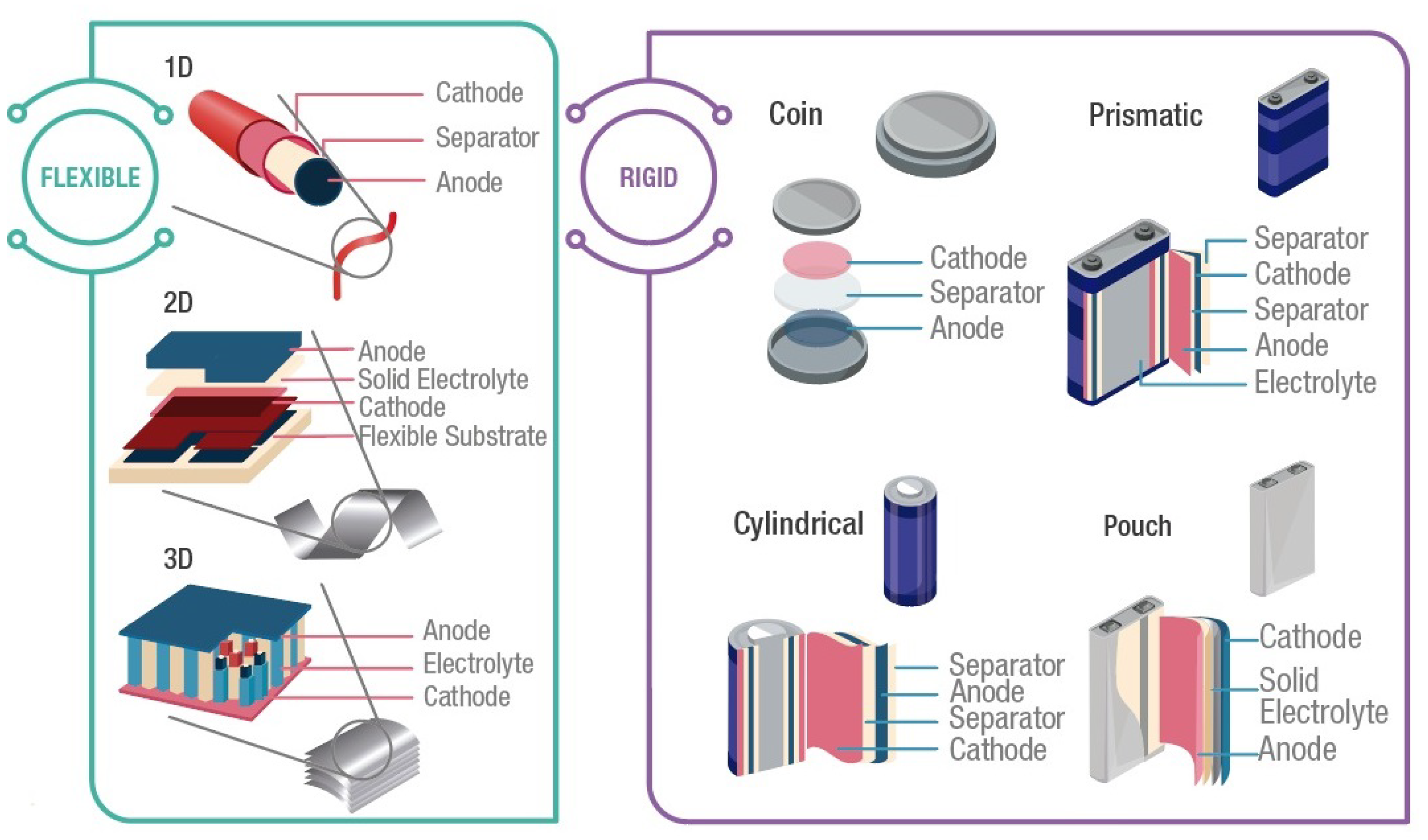
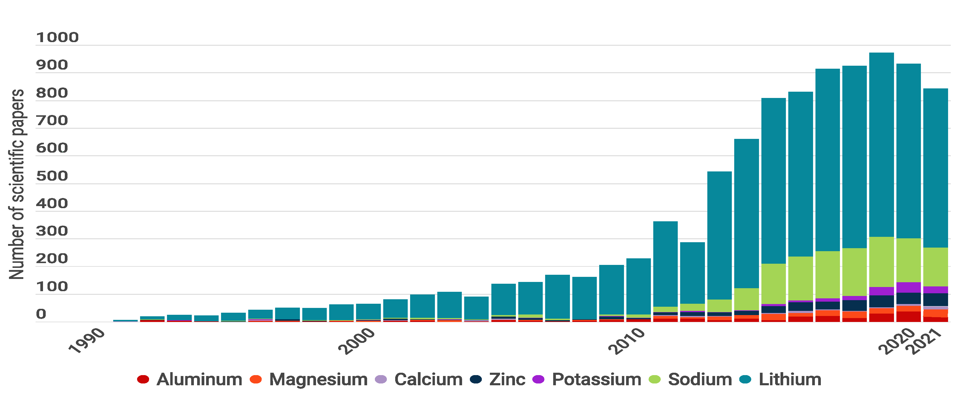
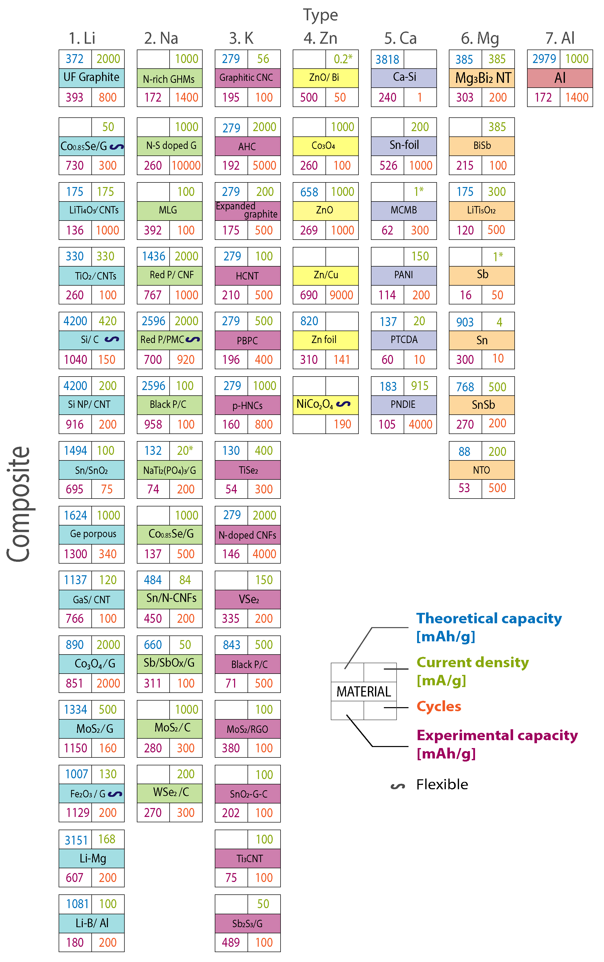
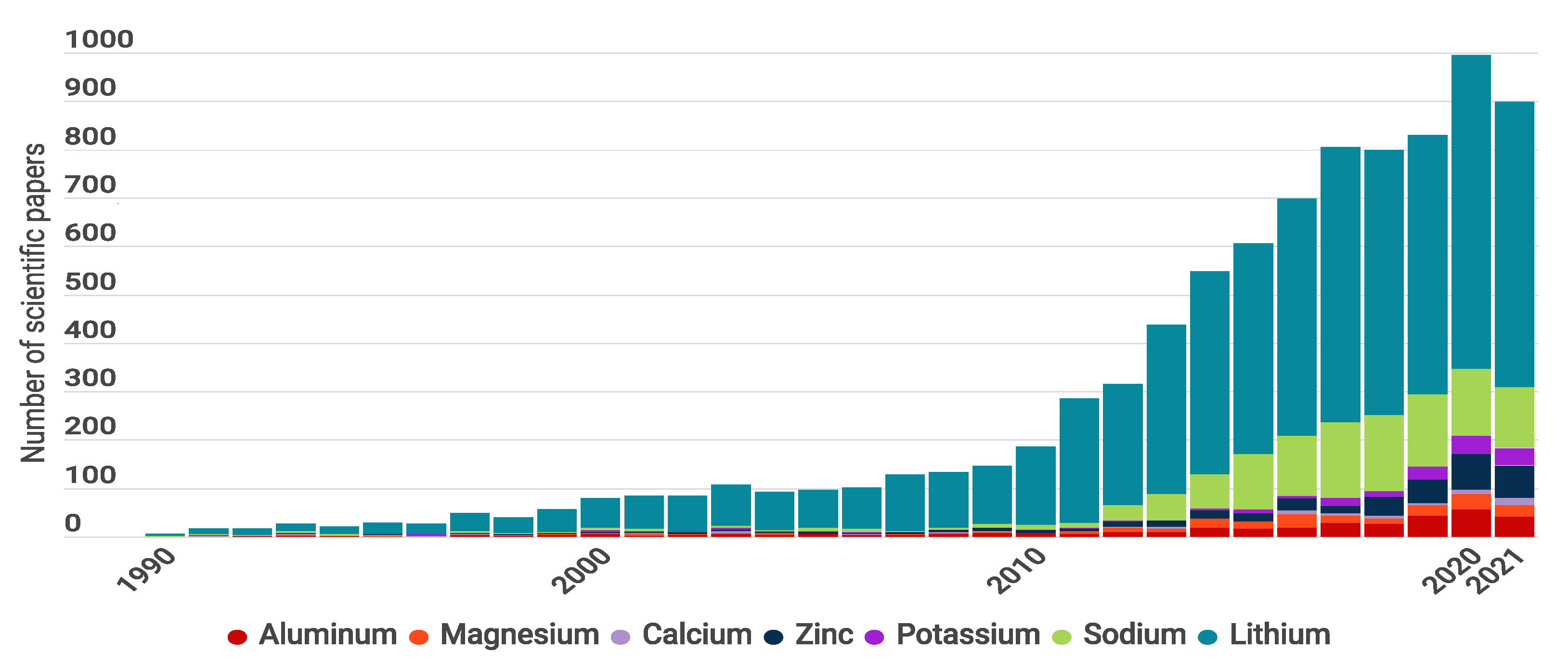
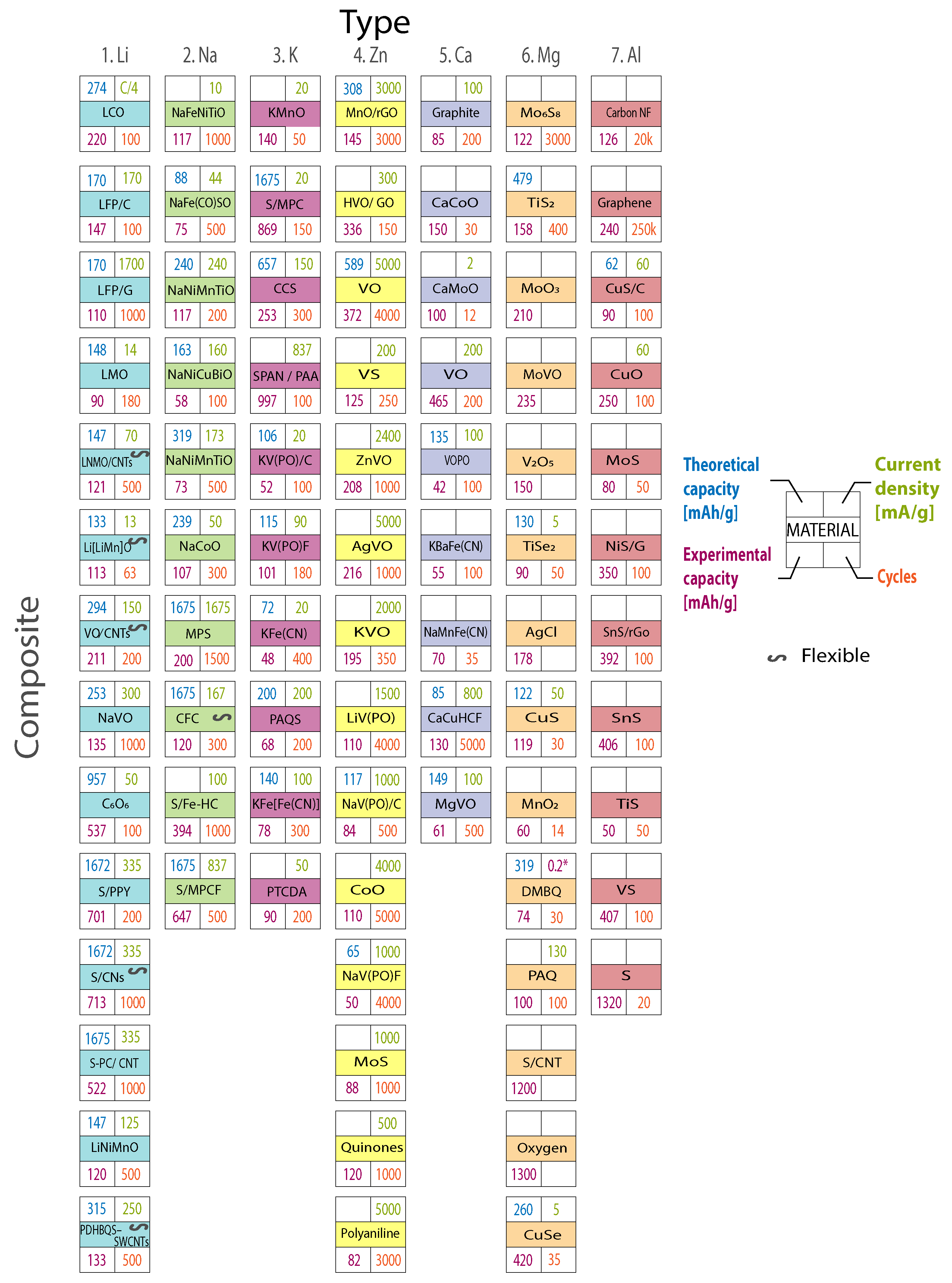
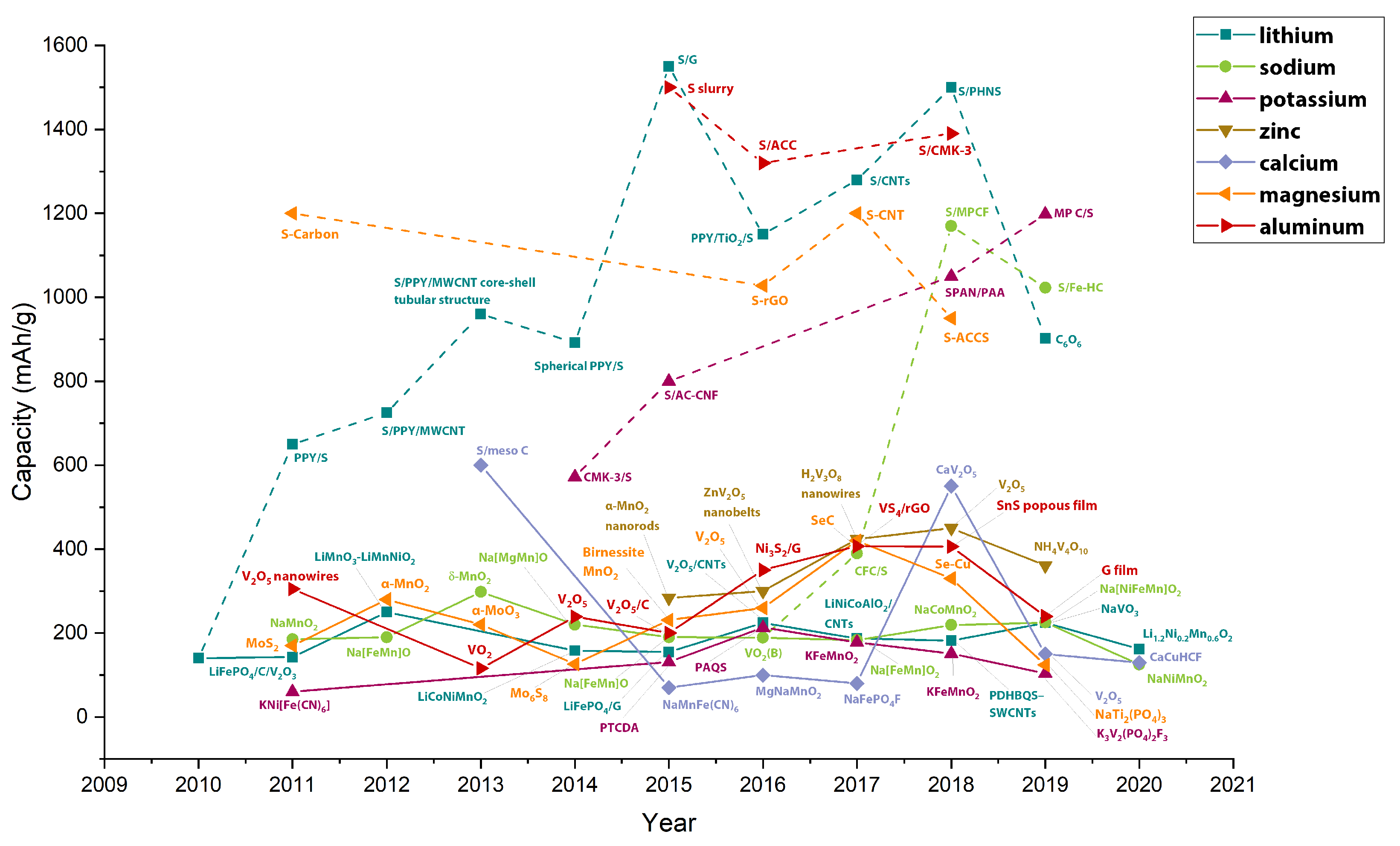
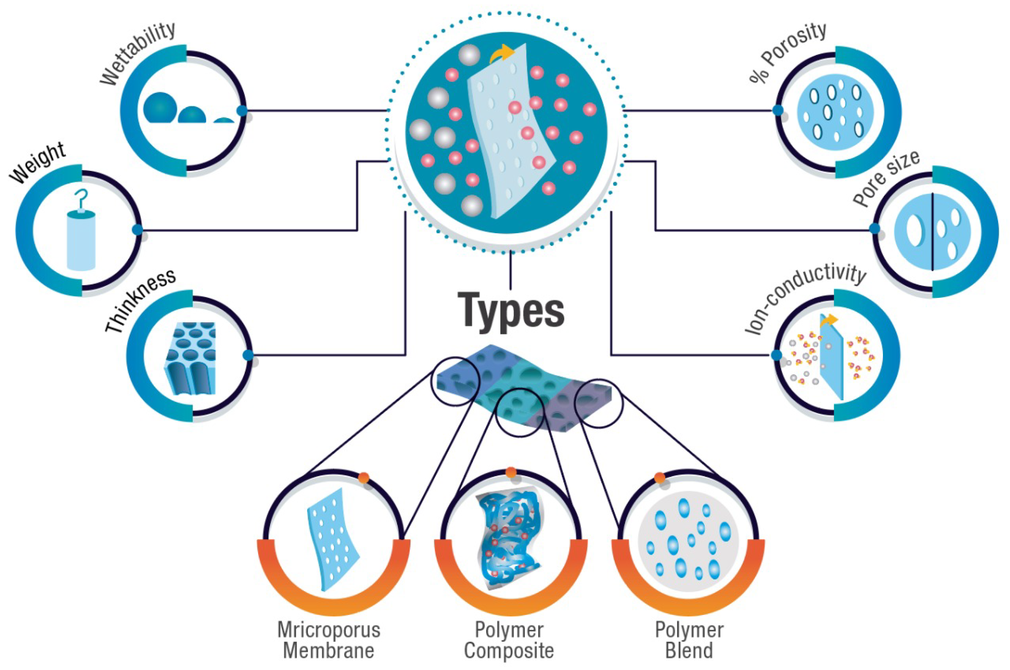
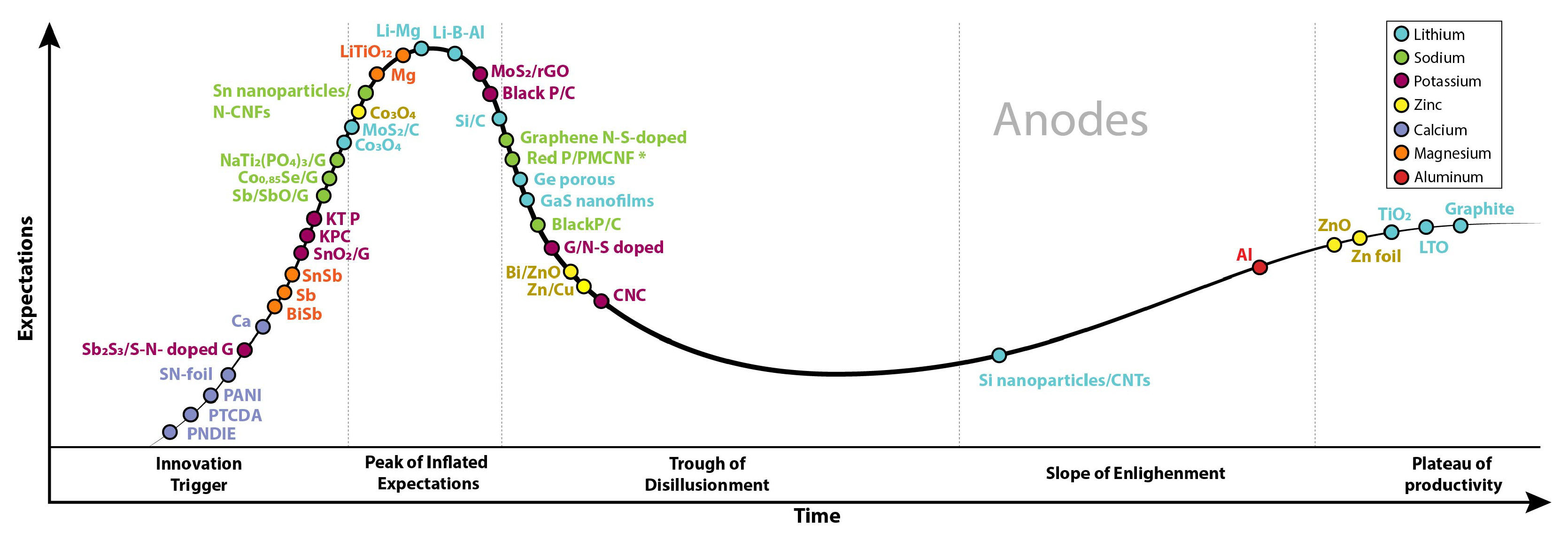
Table 17.
Additive materials for electrolytes. Source from [412].
Table 17.
Additive materials for electrolytes. Source from [412].
| Additive | Boiling Point (K) | Density (g cm) |
|---|---|---|
| TEPa | 488.15 | 1.072 |
| TMPa | 453.15 | 1.197 |
| TFPa | 355.15 | 1.594 |
| DMMPb | 453.15 | 1.145 |
| DMMEMPc | 553.15 | |
| MFEa | 333.15 | 1.529 |
| MFAa | 358.15 | 1.272 |
Table 18.
Ionic conductivity of common solid-state electrolytes.
| Polymer | S cm | Ceramic | S cm |
|---|---|---|---|
| PEO | 10−8 to 10−6 | LISICON | 10−5 to 10−3 |
| PMMA | 10−4 to 10−5 | NASICON | 10−5 to 10−3 |
| PAN | Garnet | 10−5 to 10−3 | |
| PVdF | Perovskite | 10−5 to 10−3 | |
| PVdF-HFP | Sulfide | 10−7 to 10−3 | |
| PVdF-TrFE | LiPON | 10−6 | |
| PPO | |||
| PVA | |||
| PAM | |||
| PNA | |||
| PAA | |||
| PNIPAM |
SSE can be made from polymers [405,406] or ceramics [413,414,415]. Solid polymer electrolytes (SPEs) have been explored as a replacement for liquid electrolytes to overcome flammable and volatile behavior in liquid electrolytes. Although SPEs are a versatile material to form films with good viscoelasticity (e.g., polyethylene oxide (PEO)) the main challenges of SPEs are low ionic conductivity at room temperature (10−8 S cm−1 to 10−5 S cm−1), low ion transference number (ITN < 0.3), and poor electrochemical stability [416]. On the other hand, solid ceramic electrolytes have a high stability in contact with metal anodes and have wide electrochemical windows. The use of ceramic materials is limited by their inherent fragility, reducing its application as a flexible electrolyte [413]. Solid ceramic electrolytes can be divided into two types: oxide- and sulfide based.
Polymer electrolytes can be classified into gel polymer electrolytes and dry polymer electrolytes. Gel polymer electrolytes are made by dissolving the salts into a polar solvent or an ionic liquid and by adding it to a polymer host, creating a composite. Although this composite does not exhibit porosity, it does have ionic conductivity, electrochemical stability, a melting temperature, wettability, and mechanical properties. The salts in the polymer matrix allow the ionic conduction in polymer electrolytes. Polymer materials include polyvinylidene fluoride (PVDF), polyvinyl chloride (PVC), poly ethylene oxide (PEO), SCT, polyethylene glycol bis-carbamate PEGBCDMA, and polytetrahydrofuran (PTHF). According to the polymer-solvent-ion, gel polymer electrolytes can have two kinds of interactions: (1) strong polymer-solvent interactions, which have high chemical stability and low ion transport; or (2) weak polymer–solvent interactions, which have low chemical stability and fast ion transport. Dry polymer electrolytes are a solvent-free polymer–salt system composed of electrolytic salt dissolved in a polymer matrix. These electrolytes open the door to safety, flexibility, robustness, novel thicknesses and shapes, and new possibilities of use for electrochemical devices.
The separator is a porous membrane located between negative and positive electrodes, serving as the physical separation between the anode and the cathode [417]. A separator function is a membrane which helps to avoid short circuits and control the movement of ions from/to electrodes. An ideal separator for batteries should have high ionic conductivity and excellent mechanical and thermal stability.
Critical separator characteristics that influence properties are: thickness, weight, ionic conductivity, porosity, pore size, and wettability (Figure 12). Thickness, which refers to a film’s width, and weight affect energy and power density as well as the swelling process and mechanical properties. Ionic conductivity is a measure of the movement of an ion from one site to another, and it can vary according to porosity and the separator’s morphology. Porosity is a measure of the holes (void spaces) in the separator, and it is estimated in three ways: (1) a fraction of voids’ volume over the total volume, (2) between 0 and 1, or (3) as a percentage. The porous volume also affects the uptake of the electrolyte and the mechanical strength. Pore size is the dimension of the pore, and it is critical to reducing dendrite growth. Wettability is the separator surface’s ability to maintain contact with a liquid, and it is essential for producing good ionic conductivity and rate capability of a battery.
Common materials used for battery separators are polymeric and ceramic materials. Polymer materials are used in commercial applications since the swelling process, essential in obtaining a high ionic conductivity and high ion transport number in the separator membrane, is more efficient in polymers. The use of polymer separators is limited by their poor thermal stability and wetting ability. Ceramic materials have higher thermal stability than polymerics, but their use in commercial applications is limited by poor mechanical stability, scalability, and high production costs [17].
Separators can be divided into three main types: microporous membranes, composite membranes, and polymer blends [17]. Microporous membranes are commonly composed of porous polymer layers. These membranes can be classified into four categories according to their fabrication method, structure (pore size and porosity), and composition. These four categories are: (1) single layer membranes that include membranes with a porosity between 20% to 80% and a pore size ; (2) non-woven membranes with a porosity between 60% to 75% and a pore size ; (3) electrospun membranes that possess a high porosity above 70% and a pore size ; and (4) membranes with an external surface modification to develop specific properties by coatings, plasma treatment, polymer grafting, and chemical modification.
In addition, composite membranes are analogous to the microporous membrane but include micro/nanofillers inside the polymer to improve its thermal, mechanical, or electrochemical properties. Common materials used as fillers are inert ceramic oxides (SiO, TiO, AlO), ferroelectric materials (BaTiO), super acid oxides (CaCO, AlI, AlPO, FeO,Zr−O−SO4, BN, Sn, NiO, CuO, nano−ZnO), clays (MMT), carbonaceous fillers (CNT), molecular sieves and zeolites (ZSM, NaY, SBA-15, MCM-41, MOF-5). Moreover, filler types are divided into two main classes: passive and active classes. The difference is that passive fillers do not directly contribute to the conduction process, while the active fillers participate in the conduction process.
Finally, polymer blend membranes incorporate two or more polymers to improve separator performance through complementary properties. Common polymers for polymer blends are PVDF, P(VDF-HFP), PEO, PAN, PMMA, PE, and PVC.
5.1. Lithium Batteries
Liquid electrolyte solutions for commercial and research Li-based batteries usually contain Li salts, such as lithium hexafluorophosphate (LiPF6), lithium tetrafluoroborate (LiBF4), lithium perchlorate (LiClO4), lithium hexafluroarsenate (LiAsF6), lithium trifluoromethanesulfonate (LiCF3SO3) or lithium bis (trifluoromethanesulfonimide Li(CF3SO2)2N) (Table 16), and non-aqueous solvents, such as DME, DMC, DEC, PC, EC and -butyrolactone (BL) (Table 15).
LiPF6 is used in commercial LIB, and it has been shown to be a good ion conductor (2.4 mS cm−1 to 6.2 mS cm−1) with EC:DEC or PC solvents, and has a high level of solubility in organic plasticizers [418,419]. The main challenge of using LiPF6 is poor thermal stability since the decomposition reaction of LiPF6 = PF5+LiF is above . To improve LiPF6 thermal and hydrolytic stability, LiBF4 has been studied. The use of LiBF4 is limited in practical applications by a low ionic conductivity ( mS cm−1) due to its poor ion dissociation, a narrow electrochemical stable window ( ), and the lack of a stable solid electrolyte interface (SEI) layer [419].
Electrolytes are also researched to improve the performance of novel materials and chemical composition. For example, N-butyl-N-methylpyrrolidinium bis(fluorosulfonyl) imide (Pyr14FSI) has been studied to reduce the capacity and voltage fading in cobalt-free material such as Li1.2Ni0.2Mn0.6O2 [420]. 0.8Pyr14FSI−0.2LiTFSI was synthesized to evaluate this impact on the cathode material. As a result, the electrolyte abolished the structural modification of the cathode that is caused by side reactions, improving the cycling stability when compared with conventional carbonate-based electrolytes. The tested battery with this ionic liquid electrolyte showed a capacity of 219 at a current of 25 and of 144 at 250 , and it maintains a 56% of retention capacity after 2000 cycles.
Current liquid electrolytes have some technical (thermal stability) and safety challenges (flammability and explosibility) that reduce the performance and cycle life of batteries. Attempts to overcome these challenges, maintaining the ion conductivity, focus on a new generation of IL and SSE. For example, IL crystal-based electrolytic lithium salt (LiBIB) has shown both ionic liquid and liquid crystal behaviors, being an alternative to working as a salt or as a polymer solvent-free electrolyte [402]. Experimental results have shown that LiBIB has a melting point at , a good ionic conductivity (3 mS m−1), and electrochemical stability at room temperature, which are associated with the formation of fast ion-conductive tunnels.
In addition, to address mechanical requirements for novel applications (flexibility), SSEs have been researched. For example, LiBIB-like ionic liquid crystal lithium salt (LiBMB) has been combined with flexible poly (ethylene oxide) (PEO) to fabricate SSEs [404]. This material shows a maximum ionic conductivity of 0.45 mS m−1, a Li-ion transference number of 0.54, and a diffusion coefficient at . SSEs are an alternative to volatile organic solvents because they do not leak, exhibit good mechanical stability and flexibility, and prevent Li dendrite growth. The main obstacle is their lower ion-conductivity than liquids, increasing the internal resistance in the battery.
SSEs researched for Li-based batteries also include ceramic materials that can be classified into oxide- and sulfide-based materials. Oxide-based SSEs have been shown to have good chemical stability against Li metals and good ionic conductivity. For example, Li superionic conductors (LISICON) have high ionic conductivity at an elevated temperature (10−1 S cm−1 at . The practical application of LISICON is limited at room temperature due to the low ionic conductivity. Other oxide SSEs are Garnet, Perovskite-type, and Na superionic conductors (NASICON). Sulfide-based SSEs have shown superior ionic conductivity and better compatibility with electrode materials due to the lower bonding strength between S and Li. One problem related to these materials is the generation of gases if they contact oxygen and water molecules (H2S).
Separators for Li-based batteries are common polymers in a single layer membrane: polyethylene (PE), polypropylene (PP), polyethylene oxide (PEO), polyacrylonitrile (PAN), polymethyl methacrylate (PMMA), polyvinylidene fluoride (PVDF), polyvinylidene fluoride-co-hexafluoropropene (PVDF-HFP), and polyvinylidene fluoride-co-trifluoroethylene (PVDF-TrFE). These polymer types do not exhibit high thermal resistances. Alternative polymers have been explored, such as polyimide (PI), polym-phenylene isophthalamide (PMIA), polyether-ether-ketone (PEEK), polybenzimidazole (PBI), polyetherimide (PEI) and polystyrene-b-butadiene-b-styrene (SBS). In addition, eco-friendly polymers, such as cellulose, chitin, silk fibroin, and poly(vinyl alcohol) (PVA), have been proposed. These eco-friendly materials use water as the solvent and regenerate and recyclable eggshell membranes to suppress dendritic lithium growth.
5.2. Sodium Batteries
Electrolytes for Na-based batteries include carbon-based, ionic liquid, and SSE. Similar to electrolytes for Li-based batteries, liquid electrolytes in Na-based batteries join a Na-based salt, such as NaTFSI, NaClO4, NaBOB, NaPF6, NaBF4, NaFSI, NaFTFSI, NaOTf, and NaDFOB Table 16, and a non-aqueous carbonate-ester-based (DMC, DEC, PC, EC and ECM) or ether-based (TEGDME, DEGDME, and DME) solvent Table 15. Carbonate solvents have been used mainly due to their higher electrochemical stability. However, these carbonates decompose at Na metal electrodes, reducing the Coulombic efficiency. Therefore, these solvents are mixed, creating a binary (e.g., EC:DEC, EC:PC, and EC:DMC) solvent, or using an additive (e.g., fluoroethylene carbonate (FEC)) [421]. For example, a multifunctional electrolyte incorporating 2 NaTFSI in PC:FEC (1:1) has been explored to manufacture room temperature Na-S batteries. FEC and high salt concentration reduce Na polysulfides’ solubility and create a robust SEI on the Na anode upon cycling [422]. On the other hand, ether-based solvents have enabled the Na+ co-intercalation in graphite electrodes and the development of a stable SEI [409]. In addition, ether-based electrolytes could improve the reversibility of the Na metal in the stripping/deposition process, helping non dendritic growth.
Ionic liquid electrolytes consist of organic ions that allow unlimited structural variation and tune the properties, and they are focused on imidazolium, and pyrrolidinium [409].
Another alternative explored is aqueous electrolytes since they have a low cost, elevated safety, and are environmentally friendly [409]. The main obstacle to using water as a solvent is its electrochemical decomposition which hinders the selection of the electrode materials for practical applications, and also requires the elimination of residual O2 in the electrolyte, protecting electrode stability, inhibiting H3O+ co-intercalation into the electrode, and keeping efficient internal consumption of O2 and H2 produced at the cathode and anode sides.
SSEs researched for Na-based batteries have focused on polymer electrolytes, which can be categorized as dry polymers and gel polymers. The dry polymers which have been studied are poly (ethylene) oxide (PEO), poly(vinyl pyrrolidone) (PVP), polyvinyl chloride (PVC), poly(vinyl alcohol) (PVA), polyacrylonitrile (PAN), and polycarbonates. The main challenge of dry polymers is the low ionic conductivity at room temperature. On the other hand, gel polymers integrate a polymer and a liquid component that serves as a plasticizer, resulting in a material with properties between liquid and dry polymer electrolytes, such as ion conductivity in the range of 10−3 S cm−1. Polymers explored for gel polymer electrolytes include PEO, PAN, perfluorinated sulfonic membranes (NAFION type), poly(methyl methacrylate) (PMMA), and polyvinylidene fluoride (PVDF) [409].
5.3. Potassium Batteries
Electrolytes for K-based batteries face a low ionic conductivity due to the poor interaction between K-ions and solvents that lead to an insufficient solubility of K-salts. The K-salts that have been researched include: potassium bis-(fluorosulfonyl)imide KFTFSI, KClO4, potassium hexafluorophosphate KPF6, KBF4, KFSI, and KCF3SO3. KPF6 and KFSI have shown sufficient solubility (0.5 mol L−1 to 1.0 mol L−1) in solvents such as EC, DEC, PC, and DME. Currently, there continues to be an inefficiency of systematic study on nonaqueous KIB electrolytes [410].
Similar to Li- and Na-based batteries, liquid electrolytes researched in K-based batteries include ester- and ether-based electrolytes. Ester-based electrolytes (e.g., in acetonitrile (AN), EC and DMC) have shown higher ionic conductivity for K+ than for Li+ and Na+ ions, but they have little applicability due to the low solubility of salts such as KPF6 ( ) [423]. Efforts to adjust transport properties of KPF6 are directed at the low percentage of ion-pair formation, its hydrodynamic radius in the solvated state, the shape of the anion, and the KPF6 low viscosity in EC/DMC and AN.
Another challenge that should be addressed is the dissolution and shuttle reactions of the redox intermediates. One explored strategy to mitigate this effect is to increase the concentration of salt. For example, increasing the concentration of KTFSI to 5 M in DEGDME (<1.5 M in conventional ether-based electrolytes) suppresses the dissolution and shuttle reactions of K2Sx intermediates, and enables a full operation of K-S battery chemistry in a voltage range of 1.2 to 3.0 [289]. More research needs to be performed to improve the stability and cycle life.
SSE research on K-based batteries includes mostly polymer materials. For example, a poly (methyl methacrylate) (PMMA) polymer-gel infiltrated with KPF6 in EC/DEC/FEC has been explored [405], showing an ion conductivity similar to that of liquid electrolytes ( S cm−1), and preventing the growth of potassium dendrites due to cross-linked PMMA architecture produces adjustable pore sizes to form stable solid-electrolyte interphases. Another polymer studied is the gel-polymer poly (ethylene oxide) (PEO), which is also able to work with different alkali ions (Li+, Na+, K+. As a result of integrating the tailor-made star polymers in a functional PEO matrix, an ion conductivity of S cm−1 at to K+ was achieved [416]. Finally, a potassium ferrite phase, K2Fe4O7 was synthesized under hydrothermal conditions, and it exhibited an ionic conductivity of S cm−1 and an electrical conductivity of S cm−1.
5.4. Zinc Batteries
Electrolytes for Zn-based batteries are based on Zn salts, such as Zn(TFSI)2, Zn(ClO4)2, Zn(CF3SO3)2, and ZnSO4, dissolved in an aqueous or non-aqueous solvent.
Aqueous electrolytes have been widely studied in rechargeable Zn-based batteries for large-scale energy storage applications since they are very safe, cheap, environmentally friendly, and have a higher ionic conductivity. The use of aqueous solvents results in a short cycle life in the batteries due to side reactions with the Zn electrode (corrosion, hydrogen evolution, passivation, and Zn dendrite growth), limiting their use in practical applications. The main strategy explored to optimize the electrolyte performance has been to include electrolyte additives [424,425,426,427]. For example, PEG has been studied as an additive in gel electrolytes since it suppresses the corrosion on Zn surfaces and promotes the (002) crystallographic orientation of Zn, reducing Zn dendrite growth and improving the cycle life [424]. The influence of the different amounts of PEG-200 has also been studied, showing that 20(v)% PEG-200 improves battery cycle life from 10 cycles to up to 100 cycles [425], and it reduces the corrosion current density by % and increases the capacity retention by % when compared with a reference battery [424]. Another alternative that has been explored is the use of graphene oxide (GO) as an additive in ZnSO4 electrolyte to achieve a uniformly distributed electric field with reduced nucleation overpotential [426]. The results showed that the uniform electric field generated by GO’s increased the battery’s cycle life (650 ) compared to a reference battery without GO ( 96 ). An additional additive studied is diethyl ether (Et2O) and ethylene glycol (EG), which is able to work at low temperatures (263.15 to 273.15 ) [427]. Et2O possess highly polarized molecules that are absorbed by Zn foils’ protuberance, assuring a homogeneous Zn deposition and suppressing Zn dendrite growth. EG works as an anti-freezing agent by interacting with H2O molecules via hydrogen bonds, obstructing the ice crystals formation and decreasing the freezing point. The challenge of using additives has been to find the optimal amount of additives to reduce dendrite growth and anode self-corrosion but still maintain electrolyte performance.
Non-aqueous solvents have been explored as an alternative to address the challenges of using aqueous solvents. For example, the Zn(ClO4)2 acetonitrile (AN) electrolyte was tested in a battery and showed a high reversibility of the metal deposition with a discharge capacity of at and high Coulombic efficiency (% ) [428]. AN has also been tested with Zn(TFSI)2 and has exhibited a good ionic conductivity ( −1) without Zn dendrite growth that induces cycling stability ( ) and high Coulombic efficiency (% ) [429].
The use of liquid electrolytes requires incorporating a separator membrane. Most of the studies on Zn-based batteries employ filter paper or glass fiber membrane as separators. An alternative membrane based on thermal-gated poly(N-isopropylacrylamide) (PNIPAM) has been explored in hydrogel electrolytes [430]. PNIPAM is a porous structure that can be controlled by temperature to restrict the migration of ions between electrodes at high temperatures ( ) due to the formation of intramolecular hydrogen bonds shrinking the porous network. The practical application of PNIPAM is still limited by low-temperature windows, requiring additives to tune the phase transition temperature.
Another separator membrane that has been explored consists of mixed polyacrylonitrile (PAN) and lithium polysulfide (Li2S3) to create a cross-linked membrane that suppresses dendrite growth. PAN allows designing a mechanically robust skeleton, while Li2S3 enables sulfonyl functional groups to be hygroscopic and cationic selective transport characteristics, ensuring a uniform ionic flux distribution. This separator was tested in Zn/Zn symmetric cells, exhibiting 350 cycles with efficient dendrite growth suppression [431].
SSEs for Zn-based batteries are a promising alternative to address the demand for portable and wearable electronics [172]. Research on SSEs has been focused on integrating a concentrated salt with a gel polymer [298,432]. For example, a concentrated 3 Zn(CF3SO3)2 polyacrylamide gel electrolyte has been explored to achieve a durable and practical Zn battery system [298]. The designed concentrated gel electrolyte has been shown to have a high-voltage window, a wide operating temperature, and has been Zn dendrite-free. This gel electrolyte’s thin film has 1 of thickness and can be manually stretched to as long as a 600% strain. Another concentrated gel polymer studied as an electrolyte is 21 LiTFSI + 3 ZnOTf2 embedded in a PVA matrix [432]. As a result, the electrolyte exhibited an ion conductivity of ∼2.1 ×10⁻³ −1 at room temperature ( ), increased anode stability and window stability, and achieved thermal stability operating from 243.15 to 333.15 without structure modification.
5.5. Calcium Batteries
Liquid electrolytes studied for Ca batteries include common solvents such as -butyrolactone (BL), AN, tetrahydrofuran (THF), and PC, and salts such as LiAsF6, LiClO4, Ca(ClO4)2, Ca(BF4)2, TBA(BF4), and TBA(ClO4) [433]. However, the use of these materials has shown poor reversibility of Ca. The main challenge to develop rechargeable batteries is the lack of electrolytes for reversible Ca deposition since the reversible Ca electrochemistry depends on the electrolyte [433,434]. While Li anodes form an SEI in contact with organic electrolytes that only allow the Li+ conducting, the SEI formed on Ca anodes in most organic electrolytes block the Ca conducting, thus limiting the Coulombic efficiency of Ca batteries.
The first reversible Ca deposition was demonstrated in 2016, integrating a Ca(BF4)2 salt and ethylene carbonate EC: PC as the solvent at elevated temperatures (348.15 to 373.15 ) [50]. In 2019, it was reported that Ca plating/stripping in carbonate solvents could be reversible at room temperature using EC:PC solvent and Ca(BF4)2 salt [435]. EC can form stable and ion-permeable SEI, and the addition of PC creates a stable liquid solvent with a wide electrochemical stability window. The use of Ca(BF4)2 salts supports the formation of stabilizing the ion-permeable SEI.
Additional research studied the Ca deposition/stripping behaviors of Ca[B(hfip)4]2 salts by using different solvents such as THF, DME, and DGM, showing that DGM improved the reversibility of Ca deposition and stripping of the Ca[B(hfip)4]2 when compared with THF and DME [434]. DGM as an electrolyte avoids the Ca dendrite growth and the form of a passivation layer.
In addition, computational analysis helped to engineer electrolytes for Ca batteries. Solubility and solvation of Ca ions have been tested in pure carbonate solvents (EC, VC, PC, BC, DMC, EMC, and DEC), providing that the EMC and the binary mixture EC/DEC are the best electrolytes for potential Ca batteries [436].
5.6. Magnesium Batteries
Liquid electrolytes explored for Mg-based batteries integrates Mg salts such as MgTSFI2, MgCl, Mg(CB11H12)2, Mg(BBu2Ph2)2, Mg[B(HFIP)4]2, and Mg(BH) Table 16, while solvents are based mainly in non-aqueous liquids. Mg can react with esters; as a consequence, the Mg analogues of some successful Li salts (e.g., Mg((PF), and Mg(ClO)) can not be applied since they may be reduced [437].
Finding appropriate electrolytes for Mg batteries that permit efficient reversible Mg reduction and oxidation is still a challenge. Similar to Ca batteries, in Mg batteries the solvents’ decomposition and the existence of impurities causes a passivating SEI on the Mg anode that blocks Mg ions [343]. Therefore, the electrolyte solution must be stable with Mg and not be reduced by it, such as ether-based electrolytes (glymes and THF) [195].
Others Mg electrolytes researched are organoborate-based materials. Boron-based electrolytes have been shown to have a functional reaction with highly reversible magnesium deposition/dissolution. Moreover, these electrolytes could be integrated with sulfur cathodes [195]. Other electrolytes include: Borohydride-Based Mg(BH) in DME or THF, Mg-hexamethyldisilazane (Mg–HMDS) in THF, Mg aluminate chloride complex solutions (MgCl and AlCl) in THF, and Mg(TFSI) in DME.
An alternative studied to conventional electrolytes is a dual layer of liquid and polymer electrolytes [438]. Polymer electrolytes integrate PVDF, TEGDME, and Mg(OSCF), showing an Mg-ion conductivity up to −1 at . The use of solid Polymer electrolytes may reduce unwanted chemical reactions with the Mg anode. The PVDF film possesses a microsphere morphology, and the microsphere radius is reduced by adding TEGDME. In addition, the use of salt changes the PVDF morphological structure and increases the number of pores, promoting the diffusion of Mg.
5.7. Aluminum Batteries
The challenge in Al-based batteries is developing electrolytes free from Cl to avoid corrosion of battery components and to be capable of fast cationic Al transport [47]. An alternative explored is ionic liquid electrolytes, which have shown to have wide electrochemical potential windows but high viscosities that limit the fast migration of ions in the electrolyte and inhibit performance. The most common ionic liquid electrolytes include the mixtures of 1- ethyl-3-methylimidazolium chloride (EMIC) or 1-butyl-3- methylimidazolium chloride (BMIC) with AlCl. Another alternative explored is the use of urea with AlCl as electrolyte [439]. This test showed a capacity of 73 at a current density of 100 with an efficiency of % after 180 cycles. However, the battery stability required 5–10 cycles to achieve a stable capacity, changing the Coulombic efficiency from % in the first cycle to % in the 10th cycle.
Another alternative explored for rechargeable aqueous Al batteries was to use Al(OTF)–HO as an electrolyte [440]. This battery has promising applications due to the high safety of aqueous electrolytes, which facilitates cell assembly and reduces material costs. It was demonstrated that this battery allows reversible ex/insertion of Al in an aqueous electrolyte and achieves the trivalent reaction at a high redox potential. The Al contribution in capacity was identified by using the aqueous HOTF electrolyte, while the ionic liquid AlCl/[BMIM]Cl was used as a comparison to expose the effect of the aqueous electrolyte on electrochemical performance. In this case, the aqueous electrolyte was essential for enhancing kinetics and keeping the cycle life with an AlMnOnHO cathode and an Al anode when compared with other electrolytes.
6. Applications of Batteries
In this section, we focus on two major battery applications: smartphones and electric vehicles. These applications have specific battery requirements that have been addressed by research and commercial sectors. In the research field, developments have focused on solving technical challenges such as dendrite growth and side reactions to improve performance metrics of each single battery part, including capacity, voltage, Coulombic efficiency, retention capacity, and the number of cycles. In the commercial field, batteries require a high energy density and capacity, long cycle life, fast charging time, high safety, and environmental sustainability. In the next paragraphs, we discuss these two applications which do not have the most efficient batteries but are driven by an existing market that naturally evolves.
Smartphones are among the most widely used consumer electronics products, reaching 323 million units shipped in the second quarter of 2021 [441] and a sales forecast of 1535 billion units [442]. Today, smartphones are not only used as a communication device, but also include other features, such as the ability to connect to the web and other multimedia features. Standard smartphones contain a battery that offers a capacity ranging from 2000 to 5000 , allowing of continuous operation, which means that users are generally required to charge the battery twice per day. This time-consuming activity of constantly charging your phone is something that users have had to accept. To satisfy the need of the charging and discharging cycles required by these new functionalities, batteries with larger capacities are needed [1].
Electric vehicles (EVs) have recently achieved widespread notice due to progress in electrochemical energy storage technology ( mA h g−1) and cost reduction (∼$100/kWh) [3]. The first trimester of 2021 saw an increase of % in the global electric vehicle sales from 2020 [443]. The increasing EV sales are also being driven by supportive regulatory policies and additional incentives. Therefore, it is necessary to improve the quality of EV batteries if we wish to increase EV adoption rates. The most important features of EV include long-range transport ( ), low-cost transport ($45/kWh), and high-utilization transport (fast charging ) [444]. Batteries must be able to satisfy all these areas. To have long-range transport, it is necessary to manufacture batteries with energy densities of mA h g−1. To reduce the cost, abundant materials need to be used. Finally, to achieve high utilization, batteries must be capable of charging quickly in 1 h or under. Tesla, for example, has been able to address these demands of EVs, reporting a range of 650 km on a single charge and 320 after a 15 min fast charge [445].
For these advanced applications that require high energy efficiency batteries (see Figure 13), a joint effort between the commercial and research sectors is needed, not only for developing more efficient materials and manufacturing techniques, but also for establishing standards to ensure battery quality and proper performance in commercial products.
Currently, international efforts around the world connect academia and industry to face the challenge of a transition from research to commercial applications, including the development of cost-effective large-scale manufacturing. Two macro projects sponsored by the EU are mentioned here: “CObalt-free Batteries for FutuRe Automotive Applications” (COBRA) [446] and “ERA-NET for research and innovation in materials and battery technologies, supporting the European Green Deal” (M-ERA.NET3) [447]. COBRA explores using cobalt-free materials for manufacturing a battery with superior energy density, low cost, increased cycles, and reduced critical materials. The project integrates the research (3 universities) and the industrial (4 SMEs and 5 enterprises) fields to ensure an easier adaptation to production lines and the ability to scale up to meet the demands of higher market adoption. M-ERA.NET3 coordinates the efforts of several participating EU Member States in materials research and innovation for future batteries by addressing emerging technologies and related applications areas, such as surfaces, coatings, composites, additive manufacturing, or integrated materials modeling.
We also would like to call attention to the standards that commercial products should fit, and batteries are not an exception. Standards focused on device operability and compatibility have been the target of the International Electrotechnical Commission (IEC), the American National Standards Institute (ANSI), the International Standards Organization (ISO), and the Institute of Electrical and Electronics Engineers (IEEE) [448,449]. These are standards for conventional batteries, and more effort is needed to develop novel battery technologies.
7. Conclusions and Outlook
In this review, we discussed the spectrum of possibilities for anodes, cathodes, electrolytes, and separators, classified into seven types according to the working ions: Li, Na, K, Zn, Ca, Mg, and Al. These families allow a material selection understanding of how the working ion affects the material performance: voltage, current density, capacity, and capacity retention. We also presented the advantages and disadvantages of different materials, and which strategies have been studied to enhance their performance.
We examined metal anodes with high capacity. The use of metal anodes is still limited in its practical application due to dendrite growth and because side reactions limit a stable and long cycle life. The two main strategies explored to address some of the issues related to the use of metal anodes are (1) designing structured anodes, and (2) developing novel materials (Figure 14). The first strategy is focused on 1D, 2D, and 3D structures by adding binders or controlling the manufacturing techniques. The second is based on alternative materials that can successfully operate with the corresponding ion carrier. These materials can be classified according to their operation mechanism as alloys, intercalation, or conversion [73].
Cathodes discussed in this review have been studied in the frame of their operational mechanisms: intercalation and conversion. Intercalation cathodes offer good stability but low capacity, while conversion achieves higher capacity, but the side reactions limit their cycle life. The traditional intercalation materials are classified into three major classes according to their crystal structure: layered, spinel, and olivine structure. The next generation of cathodes is exploring conversion mechanisms, which are present in metal–sulfur and metal–oxygen technologies and offer high theoretical energy (Figure 15).
Electrolytes and separators play an important role in the batteries’ performance, as they ensure a stable and long cycle life. In this review, we studied electrolytes in two classes: liquid and SSE. Traditional liquid electrolytes consist of a salt dissolved in an organic solvent. Different levels of performance are achieved depending not only on the kinds of salt and solvent used, but also on their concentration. Today, there is a large interest in switching from organic to ionic and aqueous solvents. Ionic solvents can improve battery performance, and aqueous solvents can reduce battery cost and they are more environmentally friendly. The wide range of possibilities makes it difficult to have a clear view of the electrolyte research pathway going forward. Liquid electrolytes have a high ion conductivity, resulting in faster charging but causing safety concerns. In contrast, SSEs are a key component to developing FB. SSEs are safe and possess better mechanical and thermal stability than liquids. Improving the ion conductivity is a crucial factor to manufacture safe and practical SSE for novel battery requirements.
Battery demand for the seven ion families batteries discussed will come from all the emerging technologies envisioned by the authors in Figure 13: Internet of Things (Li, Zn, Al), reconfigurable wearables (Li, Zn, Al), sports tattoos (Zn, Al), large-scale energy storage (Na,K, Mg, Ca), unmanned aerial vehicle (Li, K, Ca, Mg), metaverse (Li, Na, Zn, ), intelligent virtual assistant ( Ca, Mg, Al) and pet robotics (K, Ca, Mg, Al). Since the applications will grow with the human endlessly needs and creativity, professionals and researchers who are designing and manufacturing novel materials will have to face the need not only to set up the materials’ technical criteria for ion batteries, but interconnected criteria that emerge on the sustainability of supply and demand challenges.
This review is expected to be useful for professionals and researchers who are designing and manufacturing novel materials and need to set up technical criteria for batteries. Figure 14 and Figure 15 could give an overview of the materials for anodes and cathodes. Although most of them are in the innovation and high expectations stage, exciting new battery developments are just around the corner and will undoubtedly have an impact on the way we live.
In our society with 222 years of battery dependency, we cannot imagine the evolution of technology without a power cell. With the proliferation of home appliances, IoT devices acquiring massive amounts of data, artificial intelligence algorithms running on embedded systems, and many applications with many devices, the energy demand appears to proliferate with human technological creativity. However, it seems that nature sets an upper limit; resources are not unlimited. Therefore, we cannot only focus on optimizing battery metrics but also on the sustainability of materials and the availability of exploration sites. Batteries must explore three fronts: material flow analysis (MFA), life cycle assessment (LCA), and battery quantity reduction (RA). In addition, we must start training our disruptive thinking to go beyond the dependence on batteries and integrate a new self-powered option that will optimize the dimensions and resources of the systems. This is the tug-of-war in which we find ourselves as a society. On the one hand, the need to remotely and permanently power billions of devices with high current densities and long life cycles. On the other hand, the enormous pressure in the exploitation of increasingly scarce minerals leads us to the need to be very disruptive in selecting materials for the following battery technologies.
Author Contributions
Conceptualization, W.P., J.A.P.-T. and A.A. (equal contribution); methodology W.P., J.A.P.-T. and A.A. (equal contribution); investigation, W.P., J.A.P.-T. and A.A. (equal contribution); writing—original draft preparation, W.P., J.A.P.-T. and A.A. (equal contribution); writing—review and editing, W.P., J.A.P.-T. and A.A. (equal contribution); visualization, W.P., J.A.P.-T. and A.A. (equal contribution); supervision, J.A.P.-T. and A.A. (equal contribution); funding acquisition, J.A.P.-T. and A.A. (equal contribution). All authors have read and agreed to the published version of the manuscript.
Funding
This research received no external funding.
Institutional Review Board Statement
Not applicable.
Data Availability Statement
Not applicable.
Acknowledgments
The authors acknowledge the financial provided by the Vice Presidency for Research & Creation publication fund at Universidad de los Andes, Colombia. Wendy Pantoja was supported by Center for Interdisciplinary Studies in Basic and Applied Complexity, CEIBA, through Bécate Nariño scholarship. The authors thank the Language Department at Universidad de los Andes, Colombia, for the insightful comments in reviewing the manuscript.
Conflicts of Interest
The authors declare no conflict of interest.
References
- Liang, Y.; Zhao, C.; Yuan, H.; Chen, Y.; Zhang, W.; Huang, J.; Yu, D.; Liu, Y.; Titirici, M.; Chueh, Y.; et al. A review of rechargeable batteries for portable electronic devices. InfoMat 2019, 1, 6–32. [Google Scholar] [CrossRef]
- Nadeem, F.; Hussain, S.M.; Tiwari, P.K.; Goswami, A.K.; Ustun, T.S. Comparative review of energy storage systems, their roles, and impacts on future power systems. IEEE Access 2019, 7, 4555–4585. [Google Scholar] [CrossRef]
- Ding, Y.; Cano, Z.P.; Yu, A.; Lu, J.; Chen, Z. Automotive Li-Ion Batteries: Current Status and Future Perspectives. Electrochem. Energy Rev. 2019, 2, 1–28. [Google Scholar] [CrossRef]
- Zubi, G.; Dufo-López, R.; Carvalho, M.; Pasaoglu, G. The lithium-ion battery: State of the art and future perspectives. Renew. Sustain. Energy Rev. 2018, 89, 292–308. [Google Scholar] [CrossRef]
- Fan, X.; Liu, X.; Hu, W.; Zhong, C.; Lu, J. Advances in the development of power supplies for the Internet of Everything. InfoMat 2019, 1, 130–139. [Google Scholar] [CrossRef]
- Raj, A.; Steingart, D. Review—Power Sources for the Internet of Things. J. Electrochem. Soc. 2018, 165, B3130–B3136. [Google Scholar] [CrossRef]
- Salama, M.; Rosy.; Attias, R.; Yemini, R.; Gofer, Y.; Aurbach, D.; Noked, M. Metal-Sulfur Batteries: Overview and Research Methods. ACS Energy Lett. 2019, 4, 436–446. [Google Scholar] [CrossRef]
- Mao, M.; Gao, T.; Hou, S.; Wang, C. A critical review of cathodes for rechargeable Mg batteries. Chem. Soc. Rev. 2018, 47, 8804–8841. [Google Scholar] [CrossRef]
- Manthiram, A. A reflection on lithium-ion battery cathode chemistry. Nat. Commun. 2020, 11, 1550. [Google Scholar] [CrossRef]
- Mukherjee, S.; Singh, G. Two-Dimensional Anode Materials for Non-lithium Metal-Ion Batteries. ACS Appl. Energy Mater. 2019, 2, 932–955. [Google Scholar] [CrossRef]
- Liu, H.; Cheng, X.B.; Huang, J.Q.; Kaskel, S.; Chou, S.; Park, H.S.; Zhang, Q. Alloy Anodes for Rechargeable Alkali-Metal Batteries: Progress and Challenge. ACS Mater. Lett. 2019, 1, 217–229. [Google Scholar] [CrossRef]
- Puthusseri, D.; Wahid, M.; Ogale, S. Conversion-type Anode Materials for Alkali-Ion Batteries: State of the Art and Possible Research Directions. ACS Omega 2018, 3, 4591–4601. [Google Scholar] [CrossRef] [PubMed]
- Matsumoto, K.; Hwang, J.; Kaushik, S.; Chen, C.Y.; Hagiwara, R. Advances in sodium secondary batteries utilizing ionic liquid electrolytes. Energy Environ. Sci. 2019, 12, 3247–3287. [Google Scholar] [CrossRef]
- Yu, Z.; Wang, H.; Kong, X.; Huang, W.; Tsao, Y.; Mackanic, D.G.; Wang, K.; Wang, X.; Huang, W.; Choudhury, S.; et al. Molecular design for electrolyte solvents enabling energy-dense and long-cycling lithium metal batteries. Nat. Energy 2020, 5, 526–533. [Google Scholar] [CrossRef]
- Zhao, H.; Xu, J.; Yin, D.; Du, Y. Electrolytes for Batteries with Earth-Abundant Metal Anodes. Chem. A Eur. J. 2018, 24, 18220–18234. [Google Scholar] [CrossRef] [PubMed]
- Weber, C.J.; Geiger, S.; Falusi, S.; Roth, M. Material Review of Li Ion Battery Separators; American Institute of Physics: College Park, MD, USA, 2014; Volume 1597, pp. 66–81. [Google Scholar] [CrossRef]
- Costa, C.M.; Lee, Y.H.; Kim, J.H.; Lee, S.Y.; Lanceros-Méndez, S. Recent advances on separator membranes for lithium-ion battery applications: From porous membranes to solid electrolytes. Energy Storage Mater. 2019, 22, 346–375. [Google Scholar] [CrossRef]
- Winter, M.; Barnett, B.; Xu, K. Before Li Ion Batteries. Chem. Rev. 2018, 118, 11433–11456. [Google Scholar] [CrossRef]
- “Engineering and Technology History Wiki”. Milestones: Volta’s Electrical Battery Invention, 1799. 1999. Available online: https://ethw.org/ (accessed on 30 January 2022).
- Cadex Electronics Inc. When Was the Battery Invented? Cadex Electronics Inc.: Richmond, BC, Canada, 2019; Available online: https://batteryuniversity.com/learn/ (accessed on 30 January 2022).
- Viswanathan, B. Energy Sources; Elsevier: Amsterdam, The Netherlands, 2017; pp. 263–313. [Google Scholar] [CrossRef]
- Cheng, X.B.; Zhang, R.; Zhao, C.Z.; Zhang, Q. Toward Safe Lithium Metal Anode in Rechargeable Batteries: A Review. Chem. Rev. 2017, 117, 10403–10473. [Google Scholar] [CrossRef]
- Turcheniuk, K.; Bondarev, D.; Singhal, V.; Yushin, G. Ten years left to redesign lithium-ion batteries. Nature 2018, 14, 467–470. [Google Scholar] [CrossRef]
- Bernhart, W. Recycling of Lithium-Ion Batteries in the Context of Technology and Price Developments. ATZelectronics Worldw. 2019, 14, 38–43. [Google Scholar] [CrossRef]
- Zhang, C.; Zhao, H.; Lei, Y. Recent Research Progress of Anode Materials for Potassium-ion Batteries. Energy Environ. Mater. 2020, 3, 105–120. [Google Scholar] [CrossRef]
- Yao, Z.; Hegde, V.I.; Aspuru-Guzik, A.; Wolverton, C. Discovery of Calcium-Metal Alloy Anodes for Reversible Ca-Ion Batteries. Adv. Energy Mater. 2019, 9, 1802994. [Google Scholar] [CrossRef]
- Zhao, S.; Qin, B.; Chan, K.; Li, C.V.; Li, F. Recent Development of Aprotic Na-O2 Batteries. Batter. Supercaps 2019, 2, 725–742. [Google Scholar] [CrossRef]
- Lewis, D. The COVID pandemic has harmed researcher productivity—And mental health. Nature 2021. [Google Scholar] [CrossRef]
- Holland, A.; He, X. Advanced Li-Ion and beyond Lithium Batteries 2022–2032: Technologies, Players, Trends, Markets; Technical Report; IDTechEx: Cambridge, UK, 2021. [Google Scholar]
- Zhu, J.; Zhu, P.; Yan, C.; Dong, X.; Zhang, X. Recent progress in polymer materials for advanced lithium-sulfur batteries. Prog. Polym. Sci. 2019, 90, 118–163. [Google Scholar] [CrossRef]
- Xu, X.L.; Wang, S.J.; Wang, H.; Xu, B.; Hu, C.; Jin, Y.; Liu, J.B.; Yan, H. The suppression of lithium dendrite growth in lithium sulfur batteries: A review. J. Energy Storage 2017, 13, 387–400. [Google Scholar] [CrossRef]
- Zhang, X.; Chen, A.; Jiao, M.; Xie, Z.; Zhou, Z. Understanding Rechargeable Li-O2 Batteries via First-Principles Computations. Batter. Supercaps 2019, 2, 498–508. [Google Scholar] [CrossRef]
- Huang, J.; Peng, Z. Understanding the Reaction Interface in Lithium-Oxygen Batteries. Energy Environ. 2019, 2, 37–48. [Google Scholar] [CrossRef]
- Kang, J.H.; Lee, J.; Jung, J.W.; Park, J.; Jang, T.; Kim, H.S.; Nam, J.S.; Lim, H.; Yoon, K.R.; Ryu, W.H.; et al. Lithium—Air Batteries: Air-Breathing Challenges and Perspective. ACS Nano 2020, 14, 14549–14578. [Google Scholar] [CrossRef]
- Delmas, C. Sodium and Sodium-Ion Batteries: 50 Years of Research. Adv. Energy Mater. 2018, 8, 1703137. [Google Scholar] [CrossRef]
- Peters, J.; Peña Cruz, A.; Weil, M. Exploring the Economic Potential of Sodium-Ion Batteries. Batteries 2019, 5, 10. [Google Scholar] [CrossRef]
- Kumar, D.; Kuhar, S.B.; Kanchan, D. Room temperature sodium-sulfur batteries as emerging energy source. J. Energy Storage 2018, 18, 133–148. [Google Scholar] [CrossRef]
- Konarov, A.; Voronina, N.; Jo, J.H.; Bakenov, Z.; Sun, Y.K.; Myung, S.T. Present and Future Perspective on Electrode Materials for Rechargeable Zinc-Ion Batteries. ACS Energy Lett. 2018, 3, 2620–2640. [Google Scholar] [CrossRef]
- Ding, J.; Zhang, H.; Fan, W.; Zhong, C.; Hu, W.; Mitlin, D. Review of Emerging Potassium–Sulfur Batteries. Adv. Mater. 2020, 32, 1908007. [Google Scholar] [CrossRef]
- Wang, Y.; Sun, Y.; Ren, W.; Zhang, D.; Yang, Y.; Yang, J.; Wang, J.; Zeng, X.; NuLi, Y. Challenges and prospects of Mg-air batteries: A review. Energy Mater. 2022, 2, 200024. [Google Scholar] [CrossRef]
- Lee, B.; Paek, E.; Mitlin, D.; Lee, S.W. Sodium Metal Anodes: Emerging Solutions to Dendrite Growth. Chem. Rev. 2019, 119, 5416–5460. [Google Scholar] [CrossRef]
- Xiao, Y.; Abbasi, N.M.; Zhu, Y.; Li, S.; Tan, S.; Ling, W.; Peng, L.; Yang, T.; Wang, L.; Guo, X.; et al. Layered Oxide Cathodes Promoted by Structure Modulation Technology for Sodium-Ion Batteries. Adv. Funct. Mater. 2020, 30, 2001334. [Google Scholar] [CrossRef]
- Nayak, P.K.; Yang, L.; Brehm, W.; Adelhelm, P. From Lithium-Ion to Sodium-Ion Batteries: Advantages, Challenges, and Surprises. Angew. Chem. Int. Ed. 2018, 57, 102–120. [Google Scholar] [CrossRef]
- Electric VehicleTeam. A Guide to Understanding Battery Specifications; Electric VehicleTeam: Cambridge, MA, USA, 2008. [Google Scholar]
- Farahani, S. ZigBee Wireless Networks and Transceivers; Elsevier: Amsterdam, The Netherlands, 2008; Chapter 6; pp. 207–224. [Google Scholar] [CrossRef]
- Muench, S.; Wild, A.; Friebe, C.; Häupler, B.; Janoschka, T.; Schubert, U.S. Polymer-Based Organic Batteries. Chem. Rev. 2016, 116, 9438–9484. [Google Scholar] [CrossRef]
- Ponrouch, A.; Bitenc, J.; Dominko, R.; Lindahl, N.; Johansson, P.; Palacin, M.R. Multivalent rechargeable batteries. Energy Storage Mater. 2019, 20, 253–262. [Google Scholar] [CrossRef]
- Liang, Y.; Dong, H.; Aurbach, D.; Yao, Y. Current status and future directions of multivalent metal-ion batteries. Nat. Energy 2020, 5, 646–656. [Google Scholar] [CrossRef]
- Jayaprakash, N.; Das, S.K.; Archer, L.A. The rechargeable aluminum-ion battery. Chem. Commun. 2011, 47, 12610. [Google Scholar] [CrossRef] [PubMed]
- Ponrouch, A.; Frontera, C.; Bardé, F.; Palacín, M.R. Towards a calcium-based rechargeable battery. Nat. Mater. 2016, 15, 169–172. [Google Scholar] [CrossRef] [PubMed]
- Gao, X.; Dong, Y.; Li, S.; Zhou, J.; Wang, L.; Wang, B. MOFs and COFs for Batteries and Supercapacitors. Electrochem. Energy Rev. 2020, 3, 81–126. [Google Scholar] [CrossRef]
- Poizot, P.; Dolhem, F.; Gaubicher, J. Progress in all-organic rechargeable batteries using cationic and anionic configurations: Toward low-cost and greener storage solutions? Curr. Opin. Electrochem. 2018, 9, 70–80. [Google Scholar] [CrossRef]
- Wan, F.; Zhang, L.; Wang, X.; Bi, S.; Niu, Z.; Chen, J. An Aqueous Rechargeable Zinc-Organic Battery with Hybrid Mechanism. Adv. Funct. Mater. 2018, 28, 1804975. [Google Scholar] [CrossRef]
- Lindahl, N.; Bitenc, J.; Dominko, R.; Johansson, P. Aluminum Metal—Organic Batteries with Integrated 3D Thin Film Anodes. Adv. Funct. Mater. 2020, 30, 3–9. [Google Scholar] [CrossRef]
- Zhang, X.; Dong, P.; Song, M. Metal-Organic Frameworks for High-Energy Lithium Batteries with Enhanced Safety: Recent Progress and Future Perspectives. Batter. Supercaps 2019, 2, 591–626. [Google Scholar] [CrossRef]
- Sabihuddin, S.; Kiprakis, A.E.; Mueller, M. A numerical and graphical review of energy storage technologies. Energies 2015, 8, 172–216. [Google Scholar] [CrossRef]
- Lu, Y.; Zhao, C.Z.; Yuan, H.; Hu, J.K.; Huang, J.Q.; Zhang, Q. Dry electrode technology, the rising star in solid-state battery industrialization. Matter 2022, 5, 876–898. [Google Scholar] [CrossRef]
- Liu, W.; Song, M.S.; Kong, B.; Cui, Y. Flexible and Stretchable Energy Storage: Recent Advances and Future Perspectives. Adv. Mater. 2017, 29, 1603436. [Google Scholar] [CrossRef] [PubMed]
- Isidor Buchmann. Types of Battery Cells. 2019. Available online: https://batteryuniversity.com/article/bu-301a-types-of-battery-cells (accessed on 30 January 2022).
- Copyright Epec, L. Prismatic and Pouch Battery Packs. 2021. Available online: https://www.epectec.com/batteries/prismatic-pouch-packs.html (accessed on 30 January 2022).
- Xiaoxi, H. Flexible, Printed and Thin Film Batteries 2020–2030: Technologies, Markets and Players; Technical Report; IDTechEx: Cambridge, UK, 2020. [Google Scholar]
- Song, W.; Yoo, S.; Song, G.; Lee, S.; Kong, M.; Rim, J.; Jeong, U.; Park, S. Recent Progress in Stretchable Batteries for Wearable Electronics. Batter. Supercaps 2019, 2, 181–199. [Google Scholar] [CrossRef]
- Praveen, S.; Santhoshkumar, P.; Joe, Y.C.; Senthil, C.; Lee, C.W. 3D-printed architecture of Li-ion batteries and its applications to smart wearable electronic devices. Appl. Mater. Today 2020, 20, 100688. [Google Scholar] [CrossRef]
- Qian, G.; Liao, X.; Zhu, Y.; Pan, F.; Chen, X.; Yang, Y. Designing Flexible Lithium-Ion Batteries by Structural Engineering. ACS Energy Lett. 2019, 4, 690–701. [Google Scholar] [CrossRef]
- Qu, S.; Liu, B.; Wu, J.; Zhao, Z.; Liu, J.; Ding, J.; Han, X.; Deng, Y.; Zhong, C.; Hu, W. Kirigami-Inspired Flexible and Stretchable Zinc-Air Battery Based on Metal-Coated Sponge Electrodes. ACS Appl. Mater. Interfaces 2020, 12, 54833–54841. [Google Scholar] [CrossRef]
- Liu, T.; Chen, X.; Tervoort, E.; Kraus, T.; Niederberger, M. Design and Fabrication of Transparent and Stretchable Zinc Ion Batteries. ACS Appl. Energy Mater. 2021, 4, 6166–6179. [Google Scholar] [CrossRef]
- Guo, Z.H.; Liu, M.; Cong, Z.; Guo, W.; Zhang, P.; Hu, W.; Pu, X. Stretchable Textile Rechargeable Zn Batteries Enabled by a Wax Dyeing Method. Adv. Mater. Technol. 2020, 5, 2000544. [Google Scholar] [CrossRef]
- Fu, W.; Turcheniuk, K.; Naumov, O.; Mysyk, R.; Wang, F.; Liu, M.; Kim, D.; Ren, X.; Magasinski, A.; Yu, M.; et al. Materials and technologies for multifunctional, flexible or integrated supercapacitors and batteries. Mater. Today 2021, 48, 1. [Google Scholar] [CrossRef]
- Peng, J.; Jeffrey Snyder, G. A figure of merit for flexibility. Science 2019, 366, 690–691. [Google Scholar] [CrossRef]
- Kong, L.; Tang, C.; Peng, H.; Huang, J.; Zhang, Q. Advanced energy materials for flexible batteries in energy storage: A review. SmartMat 2020, 1. [Google Scholar] [CrossRef]
- Song, J.; Yan, W.; Cao, H.; Song, Q.; Ding, H.; Lv, Z.; Zhang, Y.; Sun, Z. Material flow analysis on critical raw materials of lithium-ion batteries in China. J. Clean. Prod. 2019, 215, 570–581. [Google Scholar] [CrossRef]
- Dehghani-Sanij, A.; Tharumalingam, E.; Dusseault, M.; Fraser, R. Study of energy storage systems and environmental challenges of batteries. Renew. Sustain. Energy Rev. 2019, 104, 192–208. [Google Scholar] [CrossRef]
- Lu, J.; Chen, Z.; Pan, F.; Cui, Y.; Amine, K. High-Performance Anode Materials for Rechargeable Lithium-Ion Batteries. Electrochem. Energy Rev. 2018, 1, 35–53. [Google Scholar] [CrossRef]
- Liu, H.; Cheng, X.B.; Jin, Z.; Zhang, R.; Wang, G.; Chen, L.Q.; Liu, Q.B.; Huang, J.Q.; Zhang, Q. Recent advances in understanding dendrite growth on alkali metal anodes. EnergyChem 2019, 1, 100003. [Google Scholar] [CrossRef]
- Chang, H.; Wu, Y.R.; Han, X.; Yi, T.F. Recent developments in advanced anode materials for lithium-ion batteries. Energy Mater. 2021, 1, 24. [Google Scholar] [CrossRef]
- Xiong, X.; Zhou, Q.; Zhu, Y.; Chen, Y.; Fu, L.; Liu, L.; Yu, N.; Wu, Y.; van Ree, T. In Pursuit of a Dendrite-Free Electrolyte/Electrode Interface on Lithium Metal Anodes: A Minireview. Energy Fuels 2020, 34, 10503–10512. [Google Scholar] [CrossRef]
- Xiao, X.; Yao, W.; Tang, J.; Liu, C.; Lian, R.; Urbankowski, P.; Anayee, M.; He, S.; Li, J.; Wang, H.; et al. Interconnected Two-dimensional Arrays of Niobium Nitride Nanocrystals as Stable Lithium Host. Batter. Supercaps 2021, 4, 106–111. [Google Scholar] [CrossRef]
- Goriparti, S.; Miele, E.; De Angelis, F.; Di Fabrizio, E.; Proietti Zaccaria, R.; Capiglia, C. Review on recent progress of nanostructured anode materials for Li-ion batteries. J. Power Sources 2014, 257, 421–443. [Google Scholar] [CrossRef]
- Yang, J.; Zhou, X.Y.; Li, J.; Zou, Y.L.; Tang, J.J. Study of nano-porous hard carbons as anode materials for lithium ion batteries. Mater. Chem. Phys. 2012, 135, 445–450. [Google Scholar] [CrossRef]
- Chen, Z.; Liu, Y.; Zhang, Y.; Shen, F.; Yang, G.; Wang, L.; Zhang, X.; He, Y.; Luo, L.; Deng, S. Ultrafine layered graphite as an anode material for lithium ion batteries. Mater. Lett. 2018, 229, 134–137. [Google Scholar] [CrossRef]
- Ge, M.; Rong, J.; Fang, X.; Zhou, C. Porous Doped Silicon Nanowires for Lithium Ion Battery Anode with Long Cycle Life. Nano Lett. 2012, 12, 2318–2323. [Google Scholar] [CrossRef] [PubMed]
- Zhang, P.; Zhu, Q.; Guan, Z.; Zhao, Q.; Sun, N.; Xu, B. A Flexible Si@C Electrode with Excellent Stability Employing an MXene as a Multifunctional Binder for Lithium-Ion Batteries. ChemSusChem 2020, 13, 1621–1628. [Google Scholar] [CrossRef] [PubMed]
- Mishra, K.; Liu, X.C.; Ke, F.S.; Zhou, X.D. Porous germanium enabled high areal capacity anode for lithium-ion batteries. Compos. Part B Eng. 2019, 163, 158–164. [Google Scholar] [CrossRef]
- Xiao, X.; Li, X.; Zheng, S.; Shao, J.; Xue, H.; Pang, H. Nanostructured Germanium Anode Materials for Advanced Rechargeable Batteries. Adv. Mater. Interfaces 2017, 4, 1600798. [Google Scholar] [CrossRef]
- Medvedev, A.G.; Mikhaylov, A.A.; Grishanov, D.A.; Yu, D.Y.W.; Gun, J.; Sladkevich, S.; Lev, O.; Prikhodchenko, P.V. GeO2 Thin Film Deposition on Graphene Oxide by the Hydrogen Peroxide Route: Evaluation for Lithium-Ion Battery Anode. ACS Appl. Mater. Interfaces 2017, 9, 9152–9160. [Google Scholar] [CrossRef]
- Zhong, H.; Wu, Y.; Ding, F.; Sang, L.; Mai, Y. An artificial Li-Al interphase layer on Li-B alloy for stable lithium-metal anode. Electrochim. Acta 2019, 304, 255–262. [Google Scholar] [CrossRef]
- Kong, L.L.; Wang, L.; Ni, Z.C.; Liu, S.; Li, G.R.; Gao, X.P. Lithium—Magnesium Alloy as a Stable Anode for Lithium–Sulfur Battery. Adv. Funct. Mater. 2019, 29, 1–10. [Google Scholar] [CrossRef]
- Li, H.; Wang, Z.; Chen, L.; Huang, X. Research on Advanced Materials for Li-ion Batteries. Adv. Mater. 2009, 21, 4593–4607. [Google Scholar] [CrossRef]
- Coelho, J.; Pokle, A.; Park, S.H.; McEvoy, N.; Berner, N.C.; Duesberg, G.S.; Nicolosi, V. Lithium Titanate/Carbon Nanotubes Composites Processed by Ultrasound Irradiation as Anodes for Lithium Ion Batteries. Sci. Rep. 2017, 7, 7614. [Google Scholar] [CrossRef]
- Chen, Z.; Belharouak, I.; Sun, Y.K.; Amine, K. Titanium-Based Anode Materials for Safe Lithium-Ion Batteries. Adv. Funct. Mater. 2013, 23, 959–969. [Google Scholar] [CrossRef]
- Trang, N.T.H.; Ali, Z.; Kang, D.J. Mesoporous TiO2 spheres interconnected by multiwalled carbon nanotubes as an anode for high-performance lithium ion batteries. ACS Appl. Mater. Interfaces 2015, 7, 3676–3683. [Google Scholar] [CrossRef] [PubMed]
- Mo, R.; Lei, Z.; Sun, K.; Rooney, D. Facile Synthesis of Anatase TiO2 Quantum-Dot/Graphene-Nanosheet Composites with Enhanced Electrochemical Performance for Lithium-Ion Batteries. Adv. Mater. 2014, 26, 2084–2088. [Google Scholar] [CrossRef]
- Hwang, I.S.; Kim, J.C.; Seo, S.D.; Lee, S.; Lee, J.H.; Kim, D.W. A binder-free Ge-nanoparticle anode assembled on multiwalled carbon nanotube networks for Li-ion batteries. Chem. Commun. 2012, 48, 7061–7063. [Google Scholar] [CrossRef] [PubMed]
- Shi, Z.; Liu, M.; Naik, D.; Gole, J.L. Electrochemical properties of Li–Mg alloy electrodes for lithium batteries. J. Power Sources 2001, 92, 70–80. [Google Scholar] [CrossRef]
- Chang, J.; Huang, X.; Zhou, G.; Cui, S.; Hallac, P.B.; Jiang, J.; Hurley, P.T.; Chen, J. Multilayered Si Nanoparticle/Reduced Graphene Oxide Hybrid as a High-Performance Lithium-Ion Battery Anode. Adv. Mater. 2014, 26, 758–764. [Google Scholar] [CrossRef]
- Huang, Y.H.; Bao, Q.; Chen, B.H.; Duh, J.G. Nano-to-microdesign of marimo-like carbon nanotubes supported frameworks via in-spaced polymerization for high performance silicon lithium ion battery anodes. Small 2015, 11, 2314–2322. [Google Scholar] [CrossRef]
- Qin, J.; He, C.; Zhao, N.; Wang, Z.; Shi, C.; Liu, E.Z.; Li, J. Graphene networks anchored with Sn@Graphene as lithium ion battery anode. ACS Nano 2014, 8, 1728–1738. [Google Scholar] [CrossRef]
- Zhou, X.; Wan, L.J.; Guo, Y.G. Binding SnO2 Nanocrystals in Nitrogen-Doped Graphene Sheets as Anode Materials for Lithium-Ion Batteries. Adv. Mater. 2013, 25, 2152–2157. [Google Scholar] [CrossRef]
- Meng, X.; He, K.; Su, D.; Zhang, X.; Sun, C.; Ren, Y.; Wang, H.H.; Weng, W.; Trahey, L.; Canlas, C.P.; et al. Gallium Sulfide-Single-Walled Carbon Nanotube Composites: High-Performance Anodes for Lithium-Ion Batteries. Adv. Funct. Mater. 2014, 24, 5435–5442. [Google Scholar] [CrossRef]
- Hwang, J.Y.; Myung, S.T.; Sun, Y.K. Sodium-ion batteries: Present and future. Chem. Soc. Rev. 2017, 46, 3529–3614. [Google Scholar] [CrossRef]
- Dong, R.; Wu, F.; Bai, Y.; Wu, C. Sodium Storage Mechanism and Optimization Strategies for Hard Carbon Anode of Sodium Ion Batteries. Acta Chim. Sin. 2021, 79, 1461–1476. [Google Scholar] [CrossRef]
- Arie, A.A.; Tekin, B.; Demir, E.; Demir-Cakan, R. Hard carbons derived from waste tea bag powder as anodes for sodium ion battery. Mater. Technol. 2019, 34, 515–524. [Google Scholar] [CrossRef]
- Ding, C.; Huang, L.; Lan, J.; Yu, Y.; Zhong, W.H.; Yang, X. Superresilient Hard Carbon Nanofabrics for Sodium-Ion Batteries. Small 2020, 16, 1–9. [Google Scholar] [CrossRef]
- Wang, Y.; Zhu, W.; Guerfi, A.; Kim, C.; Zaghib, K. Roles of ti in electrode materials for sodium-ion batteries. Front. Energy Res. 2019, 7, 28. [Google Scholar] [CrossRef]
- Bayhan, Z.; Huang, G.; Yin, J.; Xu, X.; Lei, Y.; Liu, Z.; Alshareef, H.N. Two-Dimensional TiO2/TiS2Hybrid Nanosheet Anodes for High-Rate Sodium-Ion Batteries. ACS Appl. Energy Mater. 2021, 4, 8721–8727. [Google Scholar] [CrossRef]
- Morito, H.; Yamada, T.; Ikeda, T.; Yamane, H. Na-Si binary phase diagram and solution growth of silicon crystals. J. Alloy. Compd. 2009, 480, 723–726. [Google Scholar] [CrossRef]
- Xu, Y.; Swaans, E.; Basak, S.; Zandbergen, H.W.; Borsa, D.M.; Mulder, F.M. Reversible na-ion uptake in Si nanoparticles. Adv. Energy Mater. 2016, 6, 1501436. [Google Scholar] [CrossRef]
- Tseng, K.W.; Huang, S.B.; Chang, W.C.; Tuan, H.Y. Synthesis of Mesoporous Germanium Phosphide Microspheres for High-Performance Lithium-Ion and Sodium-Ion Battery Anodes. Chem. Mater. 2018, 30, 4440–4447. [Google Scholar] [CrossRef]
- Sung, G.K.; Nam, K.H.; Choi, J.H.; Park, C.M. Germanium telluride: Layered high-performance anode for sodium-ion batteries. Electrochim. Acta 2020, 331, 135393. [Google Scholar] [CrossRef]
- Ni, J.; Li, L.; Lu, J. Phosphorus: An Anode of Choice for Sodium-Ion Batteries. ACS Energy Lett. 2018, 3, 1137–1144. [Google Scholar] [CrossRef]
- Liu, Y.; Zhang, N.; Liu, X.; Chen, C.; Fan, L.Z.; Jiao, L. Red phosphorus nanoparticles embedded in porous N-doped carbon nanofibers as high-performance anode for sodium-ion batteries. Energy Storage Mater. 2017, 9, 170–178. [Google Scholar] [CrossRef]
- Wang, L.; Jiang, Z.; Li, W.; Gu, X.; Huang, L. Hybrid phosphorene/graphene nanocomposite as an anode material for Na-ion batteries: A first-principles study. J. Phys. D Appl. Phys. 2017, 50, 165501. [Google Scholar] [CrossRef]
- Sun, X.; Li, W.; Zhong, X.; Yu, Y. Superior sodium storage in phosphorus@porous multichannel flexible freestanding carbon nanofibers. Energy Storage Mater. 2017, 9, 112–118. [Google Scholar] [CrossRef]
- Zhu, J.; He, Q.; Liu, Y.; Key, J.; Nie, S.; Wu, M.; Shen, P.K. Three-dimensional, hetero-structured, Cu3P@C nanosheets with excellent cycling stability as Na-ion battery anode material. J. Mater. Chem. A 2019, 7, 16999–17007. [Google Scholar] [CrossRef]
- Kaushik, S.; Matsumoto, K.; Sato, Y.; Hagiwara, R. Vanadium phosphide–phosphorus composite as a high-capacity negative electrode for sodium secondary batteries using an ionic liquid electrolyte. Electrochem. Commun. 2019, 102, 46–51. [Google Scholar] [CrossRef]
- Liu, D.; Huang, X.; Qu, D.; Zheng, D.; Wang, G.; Harris, J.; Si, J.; Ding, T.; Chen, J.; Qu, D. Confined phosphorus in carbon nanotube-backboned mesoporous carbon as superior anode material for sodium/potassium-ion batteries. Nano Energy 2018, 52, 1–10. [Google Scholar] [CrossRef]
- Ma, M.; Yao, Y.; Wu, Y.; Yu, Y. Progress and Prospects of Transition Metal Sulfides for Sodium Storage. Adv. Fiber Mater. 2020, 2, 314–337. [Google Scholar] [CrossRef]
- Zhang, X.; Weng, W.; Gu, H.; Hong, Z.; Xiao, W.; Wang, F.; Li, W.; Gu, D. Versatile Preparation of Mesoporous Single-Layered Transition-Metal Sulfide/Carbon Composites for Enhanced Sodium Storage. Adv. Mater. 2022, 34. [Google Scholar] [CrossRef]
- Yun, Y.S.; Park, Y.U.; Chang, S.J.; Kim, B.H.; Choi, J.; Wang, J.; Zhang, D.; Braun, P.V.; Jin, H.J.; Kang, K. Crumpled graphene paper for high power sodium battery anode. Carbon 2016, 99, 658–664. [Google Scholar] [CrossRef]
- Wang, G.Z.; Feng, J.M.; Dong, L.; Li, X.F.; Li, D.J. Porous graphene anchored with Sb/SbOxas sodium-ion battery anode with enhanced reversible capacity and cycle performance. J. Alloy. Compd. 2017, 693, 141–149. [Google Scholar] [CrossRef]
- Wang, G.; Zhang, S.; Li, X.; Liu, X.; Wang, H.; Bai, J. Multi-layer graphene assembled fibers with porous structure as anode materials for highly reversible lithium and sodium storage. Electrochim. Acta 2018, 259, 702–710. [Google Scholar] [CrossRef]
- Zhang, G.; Liu, K.; Liu, S.; Song, H.; Zhou, J. Flexible Co0.85Se nanosheets/graphene composite film as binder-free anode with high Li- and Na-Ion storage performance. J. Alloy. Compd. 2018, 731, 714–722. [Google Scholar] [CrossRef]
- Jian, Z.; Zhao, B.; Liu, P.; Li, F.; Zheng, M.; Chen, M.; Shi, Y.; Zhou, H. Fe2O3 nanocrystals anchored onto graphene nanosheets as the anode material for low-cost sodium-ion batteries. Chem. Commun. 2014, 50, 1215–1217. [Google Scholar] [CrossRef] [PubMed]
- Song, J.; Yu, Z.; Gordin, M.L.; Hu, S.; Yi, R.; Tang, D.; Walter, T.; Regula, M.; Choi, D.; Li, X.; et al. Chemically bonded phosphorus/graphene hybrid as a high performance anode for sodium-ion batteries. Nano Lett. 2014, 14, 6329–6335. [Google Scholar] [CrossRef]
- Liu, Y.; Kang, H.; Jiao, L.; Chen, C.; Cao, K.; Wang, Y.; Yuan, H. Exfoliated-SnS2 restacked on graphene as a high-capacity, high-rate, and long-cycle life anode for sodium ion batteries. Nanoscale 2015, 7, 1325–1332. [Google Scholar] [CrossRef]
- Li, S.; Cao, X.; Schmidt, C.N.; Xu, Q.; Uchaker, E.; Pei, Y.; Cao, G. TiNb2O7/graphene composites as high-rate anode materials for lithium/sodium ion batteries. J. Mater. Chem. A 2016, 4, 4242–4251. [Google Scholar] [CrossRef]
- Wang, H.G.; Wu, Z.; Meng, F.L.; Ma, D.L.; Huang, X.L.; Wang, L.M.; Zhang, X.B. Nitrogen-doped porous carbon nanosheets as low-cost, high-performance anode material for sodium-ion batteries. ChemSusChem 2013, 6, 56–60. [Google Scholar] [CrossRef]
- Hu, Y.; Ma, X.; Guo, P.; Jaeger, F.; Wang, Z. Design of NaTi2(PO4)3 nanocrystals embedded in N-doped graphene sheets for sodium-ion battery anode with superior electrochemical performance. Ceram. Int. 2017, 43, 12338–12342. [Google Scholar] [CrossRef]
- Yue, X.; Huang, N.; Jiang, Z.; Tian, X.; Wang, Z.; Hao, X.; Jiang, Z.J. Nitrogen-rich graphene hollow microspheres as anode materials for sodium-ion batteries with super-high cycling and rate performance. Carbon 2018, 130, 574–583. [Google Scholar] [CrossRef]
- Ma, Y.; Guo, Q.; Yang, M.; Wang, Y.; Chen, T.; Chen, Q.; Zhu, X.; Xia, Q.; Li, S.; Xia, H. Highly doped graphene with multi-dopants for high-capacity and ultrastable sodium-ion batteries. Energy Storage Mater. 2018, 13, 134–141. [Google Scholar] [CrossRef]
- Sultana, I.; Rahman, M.M.; Ramireddy, T.; Chen, Y.; Glushenkov, A.M. High capacity potassium-ion battery anodes based on black phosphorus. J. Mater. Chem. A 2017, 5, 23506–23512. [Google Scholar] [CrossRef]
- Wu, X.; Zhao, W.; Wang, H.; Qi, X.; Xing, Z.; Zhuang, Q.; Ju, Z. Enhanced capacity of chemically bonded phosphorus/carbon composite as an anode material for potassium-ion batteries. J. Power Sources 2018, 378, 460–467. [Google Scholar] [CrossRef]
- Qian, J.; Wu, X.; Cao, Y.; Ai, X.; Yang, H. High capacity and rate capability of amorphous phosphorus for sodium ion batteries. Angew. Chem. Int. Ed. 2013, 52, 4633–4636. [Google Scholar] [CrossRef] [PubMed]
- Dahbi, M.; Yabuuchi, N.; Fukunishi, M.; Kubota, K.; Chihara, K.; Tokiwa, K.; Yu, X.F.; Ushiyama, H.; Yamashita, K.; Son, J.Y.; et al. Black Phosphorus as a High-Capacity, High-Capability Negative Electrode for Sodium-Ion Batteries: Investigation of the Electrode/Electrolyte Interface. Chem. Mater. 2016, 28, 1625–1635. [Google Scholar] [CrossRef]
- Peng, B.; Xu, Y.; Liu, K.; Wang, X.; Mulder, F.M. High-Performance and Low-Cost Sodium-Ion Anode Based on a Facile Black Phosphorus-Carbon Nanocomposite. ChemElectroChem 2017, 4, 2140–2144. [Google Scholar] [CrossRef]
- Sun, J.; Lee, H.W.; Pasta, M.; Yuan, H.; Zheng, G.; Sun, Y.; Li, Y.; Cui, Y. A phosphorene-graphene hybrid material as a high-capacity anode for sodium-ion batteries. Nat. Nanotechnol. 2015, 10, 980–985. [Google Scholar] [CrossRef] [PubMed]
- Su, D.; Dou, S.; Wang, G. Ultrathin MoS2 Nanosheets as Anode Materials for Sodium-Ion Batteries with Superior Performance. Adv. Energy Mater. 2015, 5, 1401205. [Google Scholar] [CrossRef]
- Park, S.K.; Lee, J.; Bong, S.; Jang, B.; Seong, K.D.; Piao, Y. Scalable Synthesis of Few-Layer MoS2 Incorporated into Hierarchical Porous Carbon Nanosheets for High-Performance Li- and Na-Ion Battery Anodes. ACS Appl. Mater. Interfaces 2016, 8, 19456–19465. [Google Scholar] [CrossRef]
- David, L.; Bhandavat, R.; Singh, G. MoS2/graphene composite paper for sodium-ion battery electrodes. ACS Nano 2014, 8, 1759–1770. [Google Scholar] [CrossRef]
- Wang, H.; Lan, X.; Jiang, D.; Zhang, Y.; Zhong, H.; Zhang, Z.; Jiang, Y. Sodium storage and transport properties in pyrolysis synthesized MoSe2 nanoplates for high performance sodium-ion batteries. J. Power Sources 2015, 283, 187–194. [Google Scholar] [CrossRef]
- Share, K.; Lewis, J.; Oakes, L.; Carter, R.E.; Cohn, A.P.; Pint, C.L. Tungsten diselenide (WSe2) as a high capacity, low overpotential conversion electrode for sodium ion batteries. RSC Adv. 2015, 5, 101262–101267. [Google Scholar] [CrossRef]
- Zhang, Z.; Yang, X.; Fu, Y. Nanostructured WSe2/C composites as anode materials for sodium-ion batteries. RSC Adv. 2016, 6, 12726–12729. [Google Scholar] [CrossRef]
- Zhang, W.; Liu, Y.; Guo, Z. Approaching high-performance potassium-ion batteries via advanced design strategies and engineering. Sci. Adv. 2019, 5, eaav7412. [Google Scholar] [CrossRef]
- Jian, Z.; Luo, W.; Ji, X. Carbon Electrodes for K-Ion Batteries. J. Am. Chem. Soc. 2015, 137, 11566–11569. [Google Scholar] [CrossRef] [PubMed]
- An, Y.; Fei, H.; Zeng, G.; Ci, L.; Xi, B.; Xiong, S.; Feng, J. Commercial expanded graphite as a low–cost, long-cycling life anode for potassium—Ion batteries with conventional carbonate electrolyte. J. Power Sources 2018, 378, 66–72. [Google Scholar] [CrossRef]
- Jian, Z.; Xing, Z.; Bommier, C.; Li, Z.; Ji, X. Hard Carbon Microspheres: Potassium-Ion Anode Versus Sodium-Ion Anode. Adv. Energy Mater. 2016, 6, 1501874. [Google Scholar] [CrossRef]
- Kishore, B.; G, V.; Munichandraiah, N. K2Ti4O9: A Promising Anode Material for Potassium Ion Batteries. J. Electrochem. Soc. 2016, 163, A2551–A2554. [Google Scholar] [CrossRef]
- Han, J.; Xu, M.; Niu, Y.; Li, G.N.; Wang, M.; Zhang, Y.; Jia, M.; Li, C.M. Exploration of K2Ti8O17 as an anode material for potassium-ion batteries. Chem. Commun. 2016, 52, 11274–11276. [Google Scholar] [CrossRef]
- Sha, M.; Liu, L.; Zhao, H.; Lei, Y. Anode materials for potassium-ion batteries: Current status and prospects. Carbon Energy 2020, 2, 350–369. [Google Scholar] [CrossRef]
- Sultana, I.; Rahman, M.M.; Mateti, S.; Ahmadabadi, V.G.; Glushenkov, A.M.; Chen, Y. K-ion and Na-ion storage performances of Co3O4–Fe2O3 nanoparticle-decorated super P carbon black prepared by a ball milling process. Nanoscale 2017, 9, 3646–3654. [Google Scholar] [CrossRef]
- Gao, H.; Zhou, T.; Zheng, Y.; Zhang, Q.; Liu, Y.; Chen, J.; Liu, H.; Guo, Z. CoS Quantum Dot Nanoclusters for High-Energy Potassium-Ion Batteries. Adv. Funct. Mater. 2017, 27, 1702634. [Google Scholar] [CrossRef]
- Dong, Y.; Wu, Z.S.; Zheng, S.; Wang, X.; Qin, J.; Wang, S.; Shi, X.; Bao, X. Ti3C2 MXene-Derived Sodium/Potassium Titanate Nanoribbons for High-Performance Sodium/Potassium Ion Batteries with Enhanced Capacities. ACS Nano 2017, 11, 4792–4800. [Google Scholar] [CrossRef] [PubMed]
- Han, J.; Niu, Y.; Bao, S.J.; Yu, Y.N.; Lu, S.Y.; Xu, M. Nanocubic KTi2(PO4)3 electrodes for potassium-ion batteries. Chem. Commun. 2016, 52, 11661–11664. [Google Scholar] [CrossRef] [PubMed]
- Ren, X.; Zhao, Q.; McCulloch, W.D.; Wu, Y. MoS2 as a long-life host material for potassium ion intercalation. Nano Res. 2017, 10, 1313–1321. [Google Scholar] [CrossRef]
- Xie, K.; Yuan, K.; Li, X.; Lu, W.; Shen, C.; Liang, C.; Vajtai, R.; Ajayan, P.; Wei, B. Superior Potassium Ion Storage via Vertical MoS2 “Nano-Rose” with Expanded Interlayers on Graphene. Small 2017, 13, 1701471. [Google Scholar] [CrossRef]
- Lu, Y.; Chen, J. Robust self-supported anode by integrating Sb2S3 nanoparticles with S,N-codoped graphene to enhance K-storage performance. Sci. China Chem. 2017, 60, 1533–1539. [Google Scholar] [CrossRef]
- Lei, K.; Wang, C.; Liu, L.; Luo, Y.; Mu, C.; Li, F.; Chen, J. A Porous Network of Bismuth Used as the Anode Material for High-Energy-Density Potassium-Ion Batteries. Angew. Chem. 2018, 130, 4777–4781. [Google Scholar] [CrossRef]
- Huang, Z.; Chen, Z.; Ding, S.; Chen, C.; Zhang, M. Enhanced conductivity and properties of SnO2-graphene-carbon nanofibers for potassium-ion batteries by graphene modification. Mater. Lett. 2018, 219, 19–22. [Google Scholar] [CrossRef]
- Zhang, W.; Pang, W.K.; Sencadas, V.; Guo, Z. Understanding High-Energy-Density Sn4P3 Anodes for Potassium-Ion Batteries. Joule 2018, 2, 1534–1547. [Google Scholar] [CrossRef]
- Verma, R.; Didwal, P.N.; Ki, H.S.; Cao, G.; Park, C.J. SnP3/Carbon Nanocomposite as an Anode Material for Potassium-Ion Batteries. ACS Appl. Mater. Interfaces 2019, 11, 26976–26984. [Google Scholar] [CrossRef]
- Lakshmi, V.; Chen, Y.; Mikhaylov, A.A.; Medvedev, A.G.; Sultana, I.; Rahman, M.M.; Lev, O.; Prikhodchenko, P.V.; Glushenkov, A.M. Nanocrystalline SnS2 coated onto reduced graphene oxide: Demonstrating the feasibility of a non-graphitic anode with sulfide chemistry for potassium-ion batteries. Chem. Commun. 2017, 53, 8272–8275. [Google Scholar] [CrossRef] [PubMed]
- Lian, P.; Dong, Y.; Wu, Z.S.; Zheng, S.; Wang, S.; Sun, C.; Qin, J.; Shi, X.; Bao, X. Alkalized Ti3C2 MXene nanoribbons with expanded interlayer spacing for high-capacity sodium and potassium ion batteries. Nano Energy 2017, 40, 1–8. [Google Scholar] [CrossRef]
- Naguib, M.; Adams, R.A.; Zhao, Y.; Zemlyanov, D.; Varma, A.; Nanda, J.; Pol, V.G. Electrochemical performance of MXenes as K-ion battery anodes. Chem. Commun. 2017, 53, 6883–6886. [Google Scholar] [CrossRef] [PubMed]
- Li, P.; Zheng, X.; Yu, H.; Zhao, G.; Shu, J.; Xu, X.; Sun, W.; Dou, S.X. Electrochemical potassium/lithium-ion intercalation into TiSe2: Kinetics and mechanism. Energy Storage Mater. 2019, 16, 512–518. [Google Scholar] [CrossRef]
- Yang, C.; Feng, J.; Lv, F.; Zhou, J.; Lin, C.; Wang, K.; Zhang, Y.; Yang, Y.; Wang, W.; Li, J.; et al. Metallic Graphene-Like VSe2 Ultrathin Nanosheets: Superior Potassium-Ion Storage and Their Working Mechanism. Adv. Mater. 2018, 30, 1800036. [Google Scholar] [CrossRef] [PubMed]
- Kim, H.; Yoon, G.; Lim, K.; Kang, K. A comparative study of graphite electrodes using the co-intercalation phenomenon for rechargeable Li, Na and K batteries. Chem. Commun. 2016, 52, 12618–12621. [Google Scholar] [CrossRef] [PubMed]
- Zhao, J.; Zou, X.; Zhu, Y.; Xu, Y.; Wang, C. Electrochemical Intercalation of Potassium into Graphite. Adv. Funct. Mater. 2016, 26, 8103–8110. [Google Scholar] [CrossRef]
- Komaba, S.; Hasegawa, T.; Dahbi, M.; Kubota, K. Potassium intercalation into graphite to realize high-voltage/high-power potassium-ion batteries and potassium-ion capacitors. Electrochem. Commun. 2015, 60, 172–175. [Google Scholar] [CrossRef]
- Xu, Z.; Lv, X.; Chen, J.; Jiang, L.; Lai, Y.; Li, J. Dispersion-corrected DFT investigation on defect chemistry and potassium migration in potassium-graphite intercalation compounds for potassium ion batteries anode materials. Carbon 2016, 107, 885–894. [Google Scholar] [CrossRef]
- Deng, Q.; Pei, J.; Fan, C.; Ma, J.; Cao, B.; Li, C.; Jin, Y.; Wang, L.; Li, J. Potassium salts of para-aromatic dicarboxylates as the highly efficient organic anodes for low-cost K-ion batteries. Nano Energy 2017, 33, 350–355. [Google Scholar] [CrossRef]
- Lei, K.; Li, F.; Mu, C.; Wang, J.; Zhao, Q.; Chen, C.; Chen, J. High K-storage performance based on the synergy of dipotassium terephthalate and ether-based electrolytes. Energy Environ. Sci. 2017, 10, 552–557. [Google Scholar] [CrossRef]
- Xu, W.; Wang, Y. Recent Progress on Zinc-Ion Rechargeable Batteries. Nano-Micro Lett. 2019, 11, 90. [Google Scholar] [CrossRef] [PubMed]
- Stock, D.; Dongmo, S.; Janek, J.; Schröder, D. Benchmarking Anode Concepts: The Future of Electrically Rechargeable Zinc–Air Batteries. ACS Energy Lett. 2019, 4, 1287–1300. [Google Scholar] [CrossRef]
- Yan, Y.; Zhang, Y.; Wu, Y.; Wang, Z.; Mathur, A.; Yang, H.; Chen, P.; Nair, S.; Liu, N. A Lasagna-Inspired Nanoscale ZnO Anode Design for High-Energy Rechargeable Aqueous Batteries. ACS Appl. Energy Mater. 2018, 1, 6345–6351. [Google Scholar] [CrossRef]
- Wu, Y.; Zhang, Y.; Ma, Y.; Howe, J.D.; Yang, H.; Chen, P.; Aluri, S.; Liu, N. Ion-Sieving Carbon Nanoshells for Deeply Rechargeable Zn-Based Aqueous Batteries. Adv. Energy Mater. 2018, 8, 1802470. [Google Scholar] [CrossRef]
- Stock, D.; Dongmo, S.; Miyazaki, K.; Abe, T.; Janek, J.; Schröder, D. Towards zinc-oxygen batteries with enhanced cycling stability: The benefit of anion-exchange ionomer for zinc sponge anodes. J. Power Sources 2018, 395, 195–204. [Google Scholar] [CrossRef]
- Chamoun, M.; Hertzberg, B.J.; Gupta, T.; Davies, D.; Bhadra, S.; Van Tassell, B.; Erdonmez, C.; Steingart, D.A. Hyper-dendritic nanoporous zinc foam anodes. NPG Asia Mater. 2015, 7, e178. [Google Scholar] [CrossRef]
- Yan, Z.; Wang, E.; Jiang, L.; Sun, G. Superior cycling stability and high rate capability of three-dimensional Zn/Cu foam electrodes for zinc-based alkaline batteries. RSC Adv. 2015, 5, 83781–83787. [Google Scholar] [CrossRef]
- Hwang, H.J.; Chi, W.S.; Kwon, O.; Lee, J.G.; Kim, J.H.; Shul, Y.G. Selective Ion Transporting Polymerized Ionic Liquid Membrane Separator for Enhancing Cycle Stability and Durability in Secondary Zinc-Air Battery Systems. ACS Appl. Mater. Interfaces 2016, 8, 26298–26308. [Google Scholar] [CrossRef]
- Huang, J.; Yang, Z.; Feng, Z.; Xie, X.; Wen, X. A novel ZnO@Ag@Polypyrrole hybrid composite evaluated as anode material for zinc-based secondary cell. Sci. Rep. 2016, 6, 24471. [Google Scholar] [CrossRef]
- Lee, J.; Hwang, B.; Park, M.S.; Kim, K. Improved reversibility of Zn anodes for rechargeable Zn-air batteries by using alkoxide and acetate ions. Electrochim. Acta 2016, 199, 164–171. [Google Scholar] [CrossRef]
- Kakeya, T.; Nakata, A.; Arai, H.; Ogumi, Z. Enhanced zinc electrode rechargeability in alkaline electrolytes containing hydrophilic organic materials with positive electrode compatibility. J. Power Sources 2018, 407, 180–184. [Google Scholar] [CrossRef]
- Yan, X.; Chen, Z.; Wang, Y.; Li, H.; Zhang, J. In-situ growth of ZnO nanoplates on graphene for the application of high rate flexible quasi-solid-state Ni-Zn secondary battery. J. Power Sources 2018, 407, 137–146. [Google Scholar] [CrossRef]
- Stock, D.; Dongmo, S.; Damtew, D.; Stumpp, M.; Konovalova, A.; Henkensmeier, D.; Schlettwein, D.; Schröder, D. Design Strategy for Zinc Anodes with Enhanced Utilization and Retention: Electrodeposited Zinc Oxide on Carbon Mesh Protected by Ionomeric Layers. ACS Appl. Energy Mater. 2018, 1, 5579–5588. [Google Scholar] [CrossRef]
- Parker, J.F.; Chervin, C.N.; Pala, I.R.; Machler, M.; Burz, M.F.; Long, J.W.; Rolison, D.R. Rechargeable nickel–3D zinc batteries: An energy-dense, safer alternative to lithium-ion. Science 2017, 356, 415–418. [Google Scholar] [CrossRef] [PubMed]
- Arroyo-De Dompablo, M.E.; Ponrouch, A.; Johansson, P.; Palacín, M.R. Achievements, Challenges, and Prospects of Calcium Batteries. Chem. Rev. 2020, 120, 6331–6357. [Google Scholar] [CrossRef]
- Wu, S.; Zhang, F.; Tang, Y. A Novel Calcium-Ion Battery Based on Dual-Carbon Configuration with High Working Voltage and Long Cycling Life. Adv. Sci. 2018, 5, 1701082. [Google Scholar] [CrossRef]
- Ponrouch, A.; Tchitchekova, D.; Frontera, C.; Bardé, F.; Dompablo, M.A.d.; Palacín, M. Assessing Si-based anodes for Ca-ion batteries: Electrochemical decalciation of CaSi2. Electrochem. Commun. 2016, 66, 75–78. [Google Scholar] [CrossRef]
- Wang, M.; Jiang, C.; Zhang, S.; Song, X.; Tang, Y.; Cheng, H.M. Reversible calcium alloying enables a practical room-temperature rechargeable calcium-ion battery with a high discharge voltage. Nat. Chem. 2018, 10, 667–672. [Google Scholar] [CrossRef]
- Adil, M.; Sarkar, A.; Roy, A.; Panda, M.R.; Nagendra, A.; Mitra, S. Practical Aqueous Calcium-Ion Battery Full-Cells for Future Stationary Storage. ACS Appl. Mater. Interfaces 2020, 12, 11489–11503. [Google Scholar] [CrossRef]
- Gheytani, S.; Liang, Y.; Wu, F.; Jing, Y.; Dong, H.; Rao, K.K.; Chi, X.; Fang, F.; Yao, Y. An Aqueous Ca-Ion Battery. Adv. Sci. 2017, 4, 1700465. [Google Scholar] [CrossRef] [PubMed]
- Wu, N.; Yao, W.; Song, X.; Zhang, G.; Chen, B.; Yang, J.; Tang, Y. A Calcium-Ion Hybrid Energy Storage Device with High Capacity and Long Cycling Life under Room Temperature. Adv. Energy Mater. 2019, 9, 1803865. [Google Scholar] [CrossRef]
- Tsai, P.c.; Chung, S.C.; Lin, S.k.; Yamada, A. Ab initio study of sodium intercalation into disordered carbon. J. Mater. Chem. A 2015, 3, 9763–9768. [Google Scholar] [CrossRef]
- Rodríguez-Pérez, I.A.; Yuan, Y.; Bommier, C.; Wang, X.; Ma, L.; Leonard, D.P.; Lerner, M.M.; Carter, R.G.; Wu, T.; Greaney, P.A.; et al. Mg-Ion Battery Electrode: An Organic Solid’s Herringbone Structure Squeezed upon Mg-Ion Insertion. J. Am. Chem. Soc. 2017, 139, 13031–13037. [Google Scholar] [CrossRef]
- Attias, R.; Salama, M.; Hirsch, B.; Goffer, Y.; Aurbach, D. Anode-Electrolyte Interfaces in Secondary Magnesium Batteries. Joule 2019, 3, 27–52. [Google Scholar] [CrossRef]
- Wu, N.; Lyu, Y.C.; Xiao, R.J.; Yu, X.; Yin, Y.X.; Yang, X.Q.; Li, H.; Gu, L.; Guo, Y.G. A highly reversible, low-strain Mg-ion insertion anode material for rechargeable Mg-ion batteries. NPG Asia Mater. 2014, 6, e120. [Google Scholar] [CrossRef]
- Meng, Z.; Foix, D.; Brun, N.; Dedryvère, R.; Stievano, L.; Morcrette, M.; Berthelot, R. Alloys to Replace Mg Anodes in Efficient and Practical Mg-Ion/Sulfur Batteries. ACS Energy Lett. 2019, 4, 2040–2044. [Google Scholar] [CrossRef]
- Arthur, T.S.; Singh, N.; Matsui, M. Electrodeposited Bi, Sb and Bi1-xSbx alloys as anodes for Mg-ion batteries. Electrochem. Commun. 2012, 16, 103–106. [Google Scholar] [CrossRef]
- Shao, Y.; Gu, M.; Li, X.; Nie, Z.; Zuo, P.; Li, G.; Liu, T.; Xiao, J.; Cheng, Y.; Wang, C.; et al. Highly reversible Mg insertion in nanostructured Bi for Mg ion batteries. Nano Lett. 2014, 14, 255–260. [Google Scholar] [CrossRef]
- Cheng, Y.; Shao, Y.; Parent, L.R.; Sushko, M.L.; Li, G.; Sushko, P.V.; Browning, N.D.; Wang, C.; Liu, J. Interface Promoted Reversible Mg Insertion in Nanostructured Tin-Antimony Alloys. Adv. Mater. 2015, 27, 6598–6605. [Google Scholar] [CrossRef]
- Murgia, F.; Weldekidan, E.T.; Stievano, L.; Monconduit, L.; Berthelot, R. First investigation of indium-based electrode in Mg battery. Electrochem. Commun. 2015, 60, 56–59. [Google Scholar] [CrossRef]
- Faegh, E.; Ng, B.; Hayman, D.; Mustain, W.E. Practical assessment of the performance of aluminium battery technologies. Nat. Energy 2021, 6, 21–29. [Google Scholar] [CrossRef]
- Zhang, K.; Kirlikovali, K.O.; Suh, J.M.; Choi, J.W.; Jang, H.W.; Varma, R.S.; Farha, O.K.; Shokouhimehr, M. Recent Advances in Rechargeable Aluminum-Ion Batteries and Considerations for Their Future Progress. ACS Appl. Energy Mater. 2020, 3, 6019–6035. [Google Scholar] [CrossRef]
- Liu, C.; Neale, Z.G.; Cao, G. Understanding electrochemical potentials of cathode materials in rechargeable batteries. Mater. Today 2016, 19, 109–123. [Google Scholar] [CrossRef]
- Liu, M.; Rong, Z.; Malik, R.; Canepa, P.; Jain, A.; Ceder, G.; Persson, K.A. Spinel compounds as multivalent battery cathodes: A systematic evaluation based on ab initio calculations. Energy Environ. Sci. 2015, 8, 964–974. [Google Scholar] [CrossRef]
- Wang, B.; Han, Y.; Wang, X.; Bahlawane, N.; Pan, H.; Yan, M.; Jiang, Y. Prussian Blue Analogs for Rechargeable Batteries. iScience 2018, 3, 110–133. [Google Scholar] [CrossRef]
- Wang, H.F.; Xu, Q. Materials Design for Rechargeable Metal-Air Batteries. Matter 2019, 1, 565–595. [Google Scholar] [CrossRef]
- Xing, W. High Energy Density Li-Ion Batteries with ALD Multi-Functional Modified LiCoO2 Cathode. ECS Trans. 2017, 80, 55–63. [Google Scholar] [CrossRef]
- Lu, L.; Jiang, G.; Gu, C.; Ni, J. Revisiting polyanionic LiFePO4 battery material for electric vehicles. Funct. Mater. Lett. 2021, 14, 2130006. [Google Scholar] [CrossRef]
- Wang, B.; Liu, T.; Liu, A.; Liu, G.; Wang, L.; Gao, T.; Wang, D.; Zhao, X.S. A Hierarchical Porous C@LiFePO4/Carbon Nanotubes Microsphere Composite for High-Rate Lithium-Ion Batteries: Combined Experimental and Theoretical Study. Adv. Energy Mater. 2016, 6, 1600426. [Google Scholar] [CrossRef]
- Zhang, L.; Fu, J.; Zhang, C. Mechanical Composite of LiNi0.8Co0.15Al0.05O2/Carbon Nanotubes with Enhanced Electrochemical Performance for Lithium-Ion Batteries. Nanoscale Res. Lett. 2017, 12, 376. [Google Scholar] [CrossRef]
- Muralidharan, N.; Essehli, R.; Hermann, R.P.; Amin, R.; Jafta, C.; Zhang, J.; Liu, J.; Du, Z.; Meyer, H.M.; Self, E.; et al. Lithium Iron Aluminum Nickelate, LiNixFeyAlzO2 —New Sustainable Cathodes for Next-Generation Cobalt-Free Li-Ion Batteries. Adv. Mater. 2020, 32, 2002960. [Google Scholar] [CrossRef] [PubMed]
- Zhao, T.; Chang, L.; Ji, R. Controllable preparation of Fe-containing Li-rich cathode material Li[Li1/5Fe1/10Ni3/20Mn11/20]O2 with stable high-rate properties for Li-ion batteries. Funct. Mater. Lett. 2021, 14, 2150004. [Google Scholar] [CrossRef]
- Ould Ely, T.; Kamzabek, D.; Chakraborty, D.; Doherty, M.F. Lithium-Sulfur Batteries: State of the Art and Future Directions. ACS Appl. Energy Mater. 2018, 1, 1783–1814. [Google Scholar] [CrossRef]
- Fang, R.; Chen, K.; Yin, L.; Sun, Z.; Li, F.; Cheng, H.M. The Regulating Role of Carbon Nanotubes and Graphene in Lithium-Ion and Lithium-Sulfur Batteries. Adv. Mater. 2019, 31, 1800863. [Google Scholar] [CrossRef]
- Yuan, H.; Li, H.; Zhang, T.; Li, G.; He, T.; Du, F.; Feng, S. A K2Fe4O7 superionic conductor for all-solid-state potassium metal batteries. J. Mater. Chem. A 2018, 6, 8413–8418. [Google Scholar] [CrossRef]
- Sun, Q.; Lau, K.C.; Geng, D.; Meng, X. Atomic and Molecular Layer Deposition for Superior Lithium-Sulfur Batteries: Strategies, Performance, and Mechanisms. Batter. Supercaps 2018, 1, 41–68. [Google Scholar] [CrossRef]
- Deng, C.; Wang, Z.; Wang, S.; Yu, J. Inhibition of polysulfide diffusion in lithium-sulfur batteries: Mechanism and improvement strategies. J. Mater. Chem. A 2019, 7, 12381–12413. [Google Scholar] [CrossRef]
- Yang, W.; Yang, W.; Song, A.; Sun, G.; Shao, G. 3D interconnected porous carbon nanosheets/carbon nanotubes as a polysulfide reservoir for high performance lithium–sulfur batteries. Nanoscale 2018, 10, 816–824. [Google Scholar] [CrossRef]
- Gueon, D.; Hwang, J.T.; Yang, S.B.; Cho, E.; Sohn, K.; Yang, D.K.; Moon, J.H. Spherical Macroporous Carbon Nanotube Particles with Ultrahigh Sulfur Loading for Lithium—Sulfur Battery Cathodes. ACS Nano 2018, 12, 226–233. [Google Scholar] [CrossRef]
- Ummethala, R.; Fritzsche, M.; Jaumann, T.; Balach, J.; Oswald, S.; Nowak, R.; Sobczak, N.; Kaban, I.; Rümmeli, M.H.; Giebeler, L. Lightweight, free-standing 3D interconnected carbon nanotube foam as a flexible sulfur host for high performance lithium-sulfur battery cathodes. Energy Storage Mater. 2018, 10, 206–215. [Google Scholar] [CrossRef]
- Amin, K.; Meng, Q.; Ahmad, A.; Cheng, M.; Zhang, M.; Mao, L.; Lu, K.; Wei, Z. A Carbonyl Compound-Based Flexible Cathode with Superior Rate Performance and Cyclic Stability for Flexible Lithium-Ion Batteries. Adv. Mater. 2018, 30, 1703868. [Google Scholar] [CrossRef] [PubMed]
- Wu, T.; Qi, J.; Xu, M.; Zhou, D.; Xiao, Z. Selective S/Li2S Conversion via in-Built Crystal Facet Self-Mediation: Toward High Volumetric Energy Density Lithium–Sulfur Batteries. ACS Nano 2020, 14, 15011–15022. [Google Scholar] [CrossRef] [PubMed]
- Zhao, W.; Mu, X.; He, P.; Zhou, H. Advances and Challenges for Aprotic Lithium-Oxygen Batteries using Redox Mediators. Batter. Supercaps 2019, 2, 803–819. [Google Scholar] [CrossRef]
- Jin, Y.; Yang, C.P.; Rui, X.H.; Cheng, T.; Chen, C.H. V2O3 modified LiFePO4/C composite with improved electrochemical performance. J. Power Sources 2011, 196, 5623–5630. [Google Scholar] [CrossRef]
- Wang, B.; Al Abdulla, W.; Wang, D.; Zhao, X.S. A three-dimensional porous LiFePO4 cathode material modified with a nitrogen-doped graphene aerogel for high-power lithium ion batteries. Energy Environ. Sci. 2015, 8, 869–875. [Google Scholar] [CrossRef]
- Fang, X.; Shen, C.; Ge, M.; Rong, J.; Liu, Y.; Zhang, A.; Wei, F.; Zhou, C. High-power lithium ion batteries based on flexible and light-weight cathode of LiNi0.5Mn1.5O4/carbon nanotube film. Nano Energy 2015, 12, 43–51. [Google Scholar] [CrossRef]
- Babu, G.; Kalaiselvi, N.; Bhuvaneswari, D. Synthesis and surface modification of LiCo1/3Ni1/3Mn1/3O2 for lithium battery applications. J. Electron. Mater. 2014, 43, 1062–1070. [Google Scholar] [CrossRef]
- Kong, D.; Li, X.; Zhang, Y.; Hai, X.; Wang, B.; Qiu, X.; Song, Q.; Yang, Q.H.; Zhi, L. Encapsulating V2O4 into carbon nanotubes enables the synthesis of flexible high-performance lithium ion batteries. Energy Environ. Sci. 2016, 9, 906–911. [Google Scholar] [CrossRef]
- Kim, J.H.; Fu, K.; Choi, J.; Sun, S.; Kim, J.; Hu, L.; Paik, U. Hydroxylated carbon nanotube enhanced sulfur cathodes for improved electrochemical performance of lithium-sulfur batteries. Chem. Commun. 2015, 51, 13682–13685. [Google Scholar] [CrossRef]
- Carter, R.; Davis, B.; Oakes, L.; Maschmann, M.R.; Pint, C.L. A high areal capacity lithium–sulfur battery cathode prepared by site-selective vapor infiltration of hierarchical carbon nanotube arrays. Nanoscale 2017, 9, 15018–15026. [Google Scholar] [CrossRef] [PubMed]
- Pan, H.; Cheng, Z.; Xiao, Z.; Li, X.; Wang, R. The Fusion of Imidazolium-Based Ionic Polymer and Carbon Nanotubes: One Type of New Heteroatom-Doped Carbon Precursors for High-Performance Lithium-Sulfur Batteries. Adv. Funct. Mater. 2017, 27, 1703936. [Google Scholar] [CrossRef]
- Huang, Y.; Zheng, Y.; Li, X.; Adams, F.; Luo, W.; Huang, Y.; Hu, L. Electrode Materials of Sodium-Ion Batteries toward Practical Application. ACS Energy Lett. 2018, 3, 1604–1612. [Google Scholar] [CrossRef]
- Martinez De Ilarduya, J.; Otaegui, L.; López del Amo, J.M.; Armand, M.; Singh, G. NaN3 addition, a strategy to overcome the problem of sodium deficiency in P2-Na0.67[Fe0.5Mn0.5]O2 cathode for sodium-ion battery. J. Power Sources 2017, 337, 197–203. [Google Scholar] [CrossRef]
- Wang, P.F.; You, Y.; Yin, Y.X.; Guo, Y.G. An O3-type NaNi0.5Mn0.5O2 cathode for sodium-ion batteries with improved rate performance and cycling stability. J. Mater. Chem. A 2016, 4, 17660–17664. [Google Scholar] [CrossRef]
- Wang, P.F.; Yao, H.R.; Liu, X.Y.; Yin, Y.X.; Zhang, J.N.; Wen, Y.; Yu, X.; Gu, L.; Guo, Y.G. Na+/vacancy disordering promises high-rate Na-ion batteries. Sci. Adv. 2018, 4, eaar6018. [Google Scholar] [CrossRef]
- Manzi, J.; Paolone, A.; Palumbo, O.; Corona, D.; Massaro, A.; Cavaliere, R.; Muñoz-García, A.B.; Trequattrini, F.; Pavone, M.; Brutti, S. Monoclinic and Orthorhombic NaMnO2 for Secondary Batteries: A Comparative Study. Energies 2021, 14, 1230. [Google Scholar] [CrossRef]
- Song, T.; Yao, W.; Kiadkhunthod, P.; Zheng, Y.; Wu, N.; Zhou, X.; Tunmee, S.; Sattayaporn, S.; Tang, Y. A Low-Cost and Environmentally Friendly Mixed Polyanionic Cathode for Sodium-Ion Storage. Angew. Chem. 2020, 132, 750–755. [Google Scholar] [CrossRef]
- Xie, B.; Sun, B.; Gao, T.; Ma, Y.; Yin, G.; Zuo, P. Recent progress of Prussian blue analogues as cathode materials for nonaqueous sodium-ion batteries. Coord. Chem. Rev. 2022, 460, 214478. [Google Scholar] [CrossRef]
- Hu, P.; Peng, W.; Wang, B.; Xiao, D.; Ahuja, U.; Réthoré, J.; Aifantis, K.E. Concentration-Gradient Prussian Blue Cathodes for Na-Ion Batteries. ACS Energy Lett. 2020, 5, 100–108. [Google Scholar] [CrossRef]
- Zhu, J.; Li, Y.; Huang, Y.; Ou, C.; Yuan, X.; Yan, L.; Li, W.; Zhang, H.; Shen, P.K. General Strategy To Synthesize Highly Dense Metal Oxide Quantum Dots-Anchored Nitrogen-Rich Graphene Compact Monoliths To Enable Fast and High-Stability Volumetric Lithium/Sodium Storage. ACS Appl. Energy Mater. 2019, 2, 3500–3512. [Google Scholar] [CrossRef]
- Mao, Q.; Gao, R.; Li, Q.; Ning, D.; Zhou, D.; Schuck, G.; Schumacher, G.; Hao, Y.; Liu, X. O3-type NaNi0.5Mn0.5O2 hollow microbars with exposed {0 1 0} facets as high performance cathode materials for sodium-ion batteries. Chem. Eng. J. 2020, 382, 122978. [Google Scholar] [CrossRef]
- Zhao, C.; Ding, F.; Lu, Y.; Chen, L.; Hu, Y. High-Entropy Layered Oxide Cathodes for Sodium-Ion Batteries. Angew. Chem. 2020, 132, 270–275. [Google Scholar] [CrossRef]
- Wang, P.F.; Yao, H.R.; Liu, X.Y.; Zhang, J.N.; Gu, L.; Yu, X.Q.; Yin, Y.X.; Guo, Y.G. Ti-Substituted NaNi0.5Mn0.5−xTixO2 Cathodes with Reversible O3-P3 Phase Transition for High-Performance Sodium-Ion Batteries. Adv. Mater. 2017, 29, 1700210. [Google Scholar] [CrossRef] [PubMed]
- Wang, P.F.; Guo, Y.J.; Duan, H.; Zuo, T.T.; Hu, E.; Attenkofer, K.; Li, H.; Zhao, X.S.; Yin, Y.X.; Yu, X.; et al. Honeycomb-Ordered Na3Ni1.5M0.5BiO6 (M = Ni, Cu, Mg, Zn) as High-Voltage Layered Cathodes for Sodium-Ion Batteries. ACS Energy Lett. 2017, 2, 2715–2722. [Google Scholar] [CrossRef]
- Talaie, E.; Duffort, V.; Smith, H.L.; Fultz, B.; Nazar, L.F. Structure of the high voltage phase of layered P2-Na2/3-z [Mn1/2Fe1/2]O2 and the positive effect of Ni substitution on its stability. Energy Environ. Sci. 2015, 8, 2512–2523. [Google Scholar] [CrossRef]
- Fang, Y.; Yu, X.Y.; Lou, X.W.D. A Practical High-Energy Cathode for Sodium-Ion Batteries Based on Uniform P2-Na0.7CoO2 Microspheres. Angew. Chem. 2017, 129, 5895–5899. [Google Scholar] [CrossRef]
- Mu, L.; Xu, S.; Li, Y.; Hu, Y.S.; Li, H.; Chen, L.; Huang, X. Prototype Sodium-Ion Batteries Using an Air-Stable and Co/Ni-Free O3-Layered Metal Oxide Cathode. Adv. Mater. 2015, 27, 6928–6933. [Google Scholar] [CrossRef]
- Wang, H.; Liao, X.Z.; Yang, Y.; Yan, X.; He, Y.S.; Ma, Z.F. Large-Scale Synthesis of NaNi1/3Fe1/3Mn1/3O2 as High Performance Cathode Materials for Sodium Ion Batteries. J. Electrochem. Soc. 2016, 163, A565–A570. [Google Scholar] [CrossRef]
- Wang, P.F.; You, Y.; Yin, Y.X.; Wang, Y.S.; Wan, L.J.; Gu, L.; Guo, Y.G. Suppressing the P2-O2 Phase Transition of Na0.67Mn0.67Ni0.33O2 by Magnesium Substitution for Improved Sodium-Ion Batteries. Angew. Chem. 2016, 128, 7571–7575. [Google Scholar] [CrossRef]
- Wang, L.; Song, J.; Qiao, R.; Wray, L.A.; Hossain, M.A.; Chuang, Y.D.; Yang, W.; Lu, Y.; Evans, D.; Lee, J.J.; et al. Rhombohedral Prussian White as Cathode for Rechargeable Sodium-Ion Batteries. J. Am. Chem. Soc. 2015, 137, 2548–2554. [Google Scholar] [CrossRef] [PubMed]
- Bianchini, M.; Xiao, P.; Wang, Y.; Ceder, G. Additional Sodium Insertion into Polyanionic Cathodes for Higher-Energy Na-Ion Batteries. Adv. Energy Mater. 2017, 7, 1700514. [Google Scholar] [CrossRef]
- Carter, R.; Oakes, L.; Douglas, A.; Muralidharan, N.; Cohn, A.P.; Pint, C.L. A Sugar-Derived Room-Temperature Sodium Sulfur Battery with Long Term Cycling Stability. Nano Lett. 2017, 17, 1863–1869. [Google Scholar] [CrossRef]
- Zhang, B.W.; Sheng, T.; Wang, Y.X.; Chou, S.; Davey, K.; Dou, S.X.; Qiao, S.Z. Long-Life Room-Temperature Sodium–Sulfur Batteries by Virtue of Transition-Metal-Nanocluster—Sulfur Interactions. Angew. Chem. Int. Ed. 2019, 58, 1484–1488. [Google Scholar] [CrossRef] [PubMed]
- Kim, H.; Kim, J.C.; Bo, S.; Shi, T.; Kwon, D.; Ceder, G. K-Ion Batteries Based on a P2-Type K0.6CoO2 Cathode. Adv. Energy Mater. 2017, 7, 1700098. [Google Scholar] [CrossRef]
- Vaalma, C.; Giffin, G.A.; Buchholz, D.; Passerini, S. Non-Aqueous K-Ion Battery Based on Layered K0.3MnO2 and Hard Carbon/Carbon Black. J. Electrochem. Soc. 2016, 163, A1295–A1299. [Google Scholar] [CrossRef]
- Kim, H.; Seo, D.; Kim, J.C.; Bo, S.; Liu, L.; Shi, T.; Ceder, G. Investigation of Potassium Storage in Layered P3-Type K0.5MnO2 Cathode. Adv. Mater. 2017, 29, 1702480. [Google Scholar] [CrossRef] [Green Version]
- Xiao, Z.; Meng, J.; Xia, F.; Wu, J.; Liu, F.; Zhang, X.; Xu, L.; Lin, X.; Mai, L. K+modulated K+/vacancy disordered layered oxide for high-rate and high-capacity potassium-ion batteries. Energy Environ. Sci. 2020, 13, 3129–3137. [Google Scholar] [CrossRef]
- Chihara, K.; Katogi, A.; Kubota, K.; Komaba, S. KVPO4F and KVOPO4 toward 4 volt-class potassium-ion batteries. Chem. Commun. 2017, 53, 5208–5211. [Google Scholar] [CrossRef]
- Park, W.B.; Han, S.C.; Park, C.; Hong, S.U.; Han, U.; Singh, S.P.; Jung, Y.H.; Ahn, D.; Sohn, K.S.; Pyo, M. KVP2O7 as a Robust High-Energy Cathode for Potassium-Ion Batteries: Pinpointed by a Full Screening of the Inorganic Registry under Specific Search Conditions. Adv. Energy Mater. 2018, 8, 1703099. [Google Scholar] [CrossRef]
- Lin, X.; Huang, J.; Tan, H.; Huang, J.; Zhang, B. K3V2(PO4)2F3 as a robust cathode for potassium-ion batteries. Energy Storage Mater. 2019, 16, 97–101. [Google Scholar] [CrossRef]
- Bie, X.; Kubota, K.; Hosaka, T.; Chihara, K.; Komaba, S. A novel K-ion battery: Hexacyanoferrate(ii)/graphite cell. J. Mater. Chem. A 2017, 5, 4325–4330. [Google Scholar] [CrossRef]
- Xue, L.; Li, Y.; Gao, H.; Zhou, W.; Lü, X.; Kaveevivitchai, W.; Manthiram, A.; Goodenough, J.B. Low-Cost High-Energy Potassium Cathode. J. Am. Chem. Soc. 2017, 139, 2164–2167. [Google Scholar] [CrossRef]
- Zhao, J.; Yang, J.; Sun, P.; Xu, Y. Sodium sulfonate groups substituted anthraquinone as an organic cathode for potassium batteries. Electrochem. Commun. 2018, 86, 34–37. [Google Scholar] [CrossRef]
- Zhao, Q.; Wang, J.; Lu, Y.; Li, Y.; Liang, G.; Chen, J. Oxocarbon Salts for Fast Rechargeable Batteries. Angew. Chem. Int. Ed. 2016, 55, 12528–12532. [Google Scholar] [CrossRef]
- Zhang, Q.; Wang, Z.; Zhang, S.; Zhou, T.; Mao, J.; Guo, Z. Cathode Materials for Potassium-Ion Batteries: Current Status and Perspective. Electrochem. Energy Rev. 2018, 1, 625–658. [Google Scholar] [CrossRef]
- Jian, Z.; Liang, Y.; Rodríguez-Pérez, I.A.; Yao, Y.; Ji, X. Poly(anthraquinonyl sulfide) cathode for potassium-ion batteries. Electrochem. Commun. 2016, 71, 5–8. [Google Scholar] [CrossRef] [Green Version]
- Liu, Y.; Wang, W.; Wang, J.; Zhang, Y.; Zhu, Y.; Chen, Y.; Fu, L.; Wu, Y. Sulfur nanocomposite as a positive electrode material for rechargeable potassium—Sulfur batteries. Chem. Commun. 2018, 54, 2288–2291. [Google Scholar] [CrossRef]
- Ma, R.; Fan, L.; Wang, J.; Lu, B. Confined and covalent sulfur for stable room temperature potassium-sulfur battery. Electrochim. Acta 2019, 293, 191–198. [Google Scholar] [CrossRef]
- Xiong, P.; Han, X.; Zhao, X.; Bai, P.; Liu, Y.; Sun, J.; Xu, Y. Room-Temperature Potassium–Sulfur Batteries Enabled by Microporous Carbon Stabilized Small-Molecule Sulfur Cathodes. ACS Nano 2019, 13, 2536–2543. [Google Scholar] [CrossRef]
- Sada, K.; Senthilkumar, B.; Barpanda, P. Electrochemical potassium-ion intercalation in Na:XCoO2: A novel cathode material for potassium-ion batteries. Chem. Commun. 2017, 53, 8588–8591. [Google Scholar] [CrossRef] [PubMed]
- Naveen, N.; Park, W.B.; Han, S.C.; Singh, S.P.; Jung, Y.H.; Ahn, D.; Sohn, K.S.; Pyo, M. Reversible K+-Insertion/Deinsertion and Concomitant Na+-Redistribution in P’3-Na0.52CrO2 for High-Performance Potassium-Ion Battery Cathodes. Chem. Mater. 2018, 30, 2049–2057. [Google Scholar] [CrossRef]
- Deng, T.; Fan, X.; Luo, C.; Chen, J.; Chen, L.; Hou, S.; Eidson, N.; Zhou, X.; Wang, C. Self-Templated Formation of P2-type K0.6CoO
2 Microspheres for High Reversible Potassium-Ion Batteries. Nano Lett. 2018, 18, 1522–1529. [Google Scholar] [CrossRef] [PubMed] - Wang, X.; Xu, X.; Niu, C.; Meng, J.; Huang, M.; Liu, X.; Liu, Z.; Mai, L. Earth Abundant Fe/Mn-Based Layered Oxide Interconnected Nanowires for Advanced K-Ion Full Batteries. Nano Lett. 2017, 17, 544–550. [Google Scholar] [CrossRef] [PubMed]
- Deng, T.; Fan, X.; Chen, J.; Chen, L.; Luo, C.; Zhou, X.; Yang, J.; Zheng, S.; Wang, C. Layered P2-Type K0.65Fe0.5Mn0.5O2 Microspheres as Superior Cathode for High-Energy Potassium-Ion Batteries. Adv. Funct. Mater. 2018, 28, 1800219. [Google Scholar] [CrossRef]
- Liu, C.; Luo, S.; Huang, H.; Wang, Z.; Hao, A.; Zhai, Y.; Wang, Z. K0.67Ni0.17Co0.17Mn0.66O2: A cathode material for potassium-ion battery. Electrochem. Commun. 2017, 82, 150–154. [Google Scholar] [CrossRef]
- Deng, L.; Niu, X.; Ma, G.; Yang, Z.; Zeng, L.; Zhu, Y.; Guo, L. Layered Potassium Vanadate K0.5V2O5 as a Cathode Material for Nonaqueous Potassium Ion Batteries. Adv. Funct. Mater. 2018, 28, 1800670. [Google Scholar] [CrossRef]
- Wessells, C.D.; Huggins, R.A.; Cui, Y. Copper hexacyanoferrate battery electrodes with long cycle life and high power. Nat. Commun. 2011, 2, 550. [Google Scholar] [CrossRef]
- Pei, Y.; Mu, C.; Li, H.; Li, F.; Chen, J. Low-Cost K4Fe(CN)6 as a High-Voltage Cathode for Potassium-Ion Batteries. ChemSusChem 2018, 11, 1285–1289. [Google Scholar] [CrossRef]
- Eftekhari, A. Potassium secondary cell based on Prussian blue cathode. J. Power Sources 2004, 126, 221–228. [Google Scholar] [CrossRef]
- Chong, S.; Chen, Y.; Zheng, Y.; Tan, Q.; Shu, C.; Liu, Y.; Guo, Z. Potassium ferrous ferricyanide nanoparticles as a high capacity and ultralong life cathode material for nonaqueous potassium-ion batteries. J. Mater. Chem. A 2017, 5, 22465–22471. [Google Scholar] [CrossRef]
- Jiang, X.; Zhang, T.; Yang, L.; Li, G.; Lee, J.Y. A Fe/Mn-Based Prussian Blue Analogue as a K-Rich Cathode Material for Potassium-Ion Batteries. ChemElectroChem 2017, 4, 2237–2242. [Google Scholar] [CrossRef]
- Wessells, C.D.; Peddada, S.V.; Huggins, R.A.; Cui, Y. Nickel hexacyanoferrate nanoparticle electrodes for aqueous sodium and potassium ion batteries. Nano Lett. 2011, 11, 5421–5425. [Google Scholar] [CrossRef] [PubMed]
- Nossol, E.; Souza, V.H.; Zarbin, A.J. Carbon nanotube/Prussian blue thin films as cathodes for flexible, transparent and ITO-free potassium secondary battery. J. Colloid Interface Sci. 2016, 478, 107–116. [Google Scholar] [CrossRef] [PubMed]
- Zhu, Y.h.; Yin, Y.b.; Yang, X.; Sun, T.; Wang, S.; Jiang, Y.s.; Yan, J.m.; Zhang, X.b. Transformation of Rusty Stainless-Steel Meshes into Stable, Low-Cost, and Binder-Free Cathodes for High-Performance Potassium-Ion Batteries. Angew. Chem. 2017, 129, 7989–7993. [Google Scholar] [CrossRef]
- Han, J.; Li, G.N.; Liu, F.; Wang, M.; Zhang, Y.; Hu, L.; Dai, C.; Xu, M. Investigation of K3V2(PO4)3/C nanocomposites as high-potential cathode materials for potassium-ion batteries. Chem. Commun. 2017, 53, 1805–1808. [Google Scholar] [CrossRef]
- Chen, Y.; Luo, W.; Carter, M.; Zhou, L.; Dai, J.; Fu, K.; Lacey, S.; Li, T.; Wan, J.; Han, X.; et al. Organic electrode for non-aqueous potassium-ion batteries. Nano Energy 2015, 18, 205–211. [Google Scholar] [CrossRef]
- Lu, X.; Bowden, M.E.; Sprenkle, V.L.; Liu, J. A Low Cost, High Energy Density, and Long Cycle Life Potassium-Sulfur Battery for Grid-Scale Energy Storage. Adv. Mater. 2015, 27, 5915–5922. [Google Scholar] [CrossRef]
- Wang, L.; Bao, J.; Liu, Q.; Sun, C.F. Concentrated electrolytes unlock the full energy potential of potassium-sulfur battery chemistry. Energy Storage Mater. 2019, 18, 470–475. [Google Scholar] [CrossRef]
- Yu, X.; Manthiram, A. Performance Enhancement and Mechanistic Studies of Room-Temperature Sodium-Sulfur Batteries with a Carbon-Coated Functional Nafion Separator and a Na2S/Activated Carbon Nanofiber Cathode. Chem. Mater. 2016, 28, 896–905. [Google Scholar] [CrossRef]
- Hwang, J.Y.; Kim, H.M.; Sun, Y.K. High performance potassium-sulfur batteries based on a sulfurized polyacrylonitrile cathode and polyacrylic acid binder. J. Mater. Chem. A 2018, 6, 14587–14593. [Google Scholar] [CrossRef]
- Alfaruqi, M.H.; Mathew, V.; Gim, J.; Kim, S.; Song, J.; Baboo, J.P.; Choi, S.H.; Kim, J. Electrochemically Induced Structural Transformation in a γ-MnO2 Cathode of a High Capacity Zinc-Ion Battery System. Chem. Mater. 2015, 27, 3609–3620. [Google Scholar] [CrossRef]
- Yan, M.; He, P.; Chen, Y.; Wang, S.; Wei, Q.; Zhao, K.; Xu, X.; An, Q.; Shuang, Y.; Shao, Y.; et al. Water-Lubricated Intercalation in V2O5 · nH2O for High-Capacity and High-Rate Aqueous Rechargeable Zinc Batteries. Adv. Mater. 2018, 30, 1703725. [Google Scholar] [CrossRef]
- Wang, F.; Hu, E.; Sun, W.; Gao, T.; Ji, X.; Fan, X.; Han, F.; Yang, X.Q.; Xu, K.; Wang, C. A rechargeable aqueous Zn2+-battery with high power density and a long cycle-life. Energy Environ. Sci. 2018, 11, 3168–3175. [Google Scholar] [CrossRef]
- Wei, T.; Li, Q.; Yang, G.; Wang, C. An electrochemically induced bilayered structure facilitates long-life zinc storage of vanadium dioxide. J. Mater. Chem. A 2018, 6, 8006–8012. [Google Scholar] [CrossRef]
- Ding, J.; Du, Z.; Gu, L.; Li, B.; Wang, L.; Wang, S.; Gong, Y.; Yang, S. Ultrafast Zn2+ Intercalation and Deintercalation in Vanadium Dioxide. Adv. Mater. 2018, 30, 1800762. [Google Scholar] [CrossRef] [PubMed]
- Pang, Q.; Sun, C.; Yu, Y.; Zhao, K.; Zhang, Z.; Voyles, P.M.; Chen, G.; Wei, Y.; Wang, X. H2V3O8 Nanowire/Graphene Electrodes for Aqueous Rechargeable Zinc Ion Batteries with High Rate Capability and Large Capacity. Adv. Energy Mater. 2018, 8, 1800144. [Google Scholar] [CrossRef]
- Deng, W.; Zhou, Z.; Li, Y.; Zhang, M.; Yuan, X.; Hu, J.; Li, Z.; Li, C.; Li, R. High-Capacity Layered Magnesium Vanadate with Concentrated Gel Electrolyte toward High-Performance and Wide-Temperature Zinc-Ion Battery. ACS Nano 2020, 14, 15776–15785. [Google Scholar] [CrossRef]
- Trócoli, R.; La Mantia, F. An aqueous zinc-ion battery based on copper hexacyanoferrate. ChemSusChem 2015, 8, 481–485. [Google Scholar] [CrossRef]
- Zhang, L.; Chen, L.; Zhou, X.; Liu, Z. Towards High-Voltage Aqueous Metal-Ion Batteries Beyond 1.5 V: The Zinc/Zinc Hexacyanoferrate System. Adv. Energy Mater. 2015, 5, 1400930. [Google Scholar] [CrossRef]
- Zhao, H.B.; Hu, C.J.; Cheng, H.W.; Fang, J.H.; Xie, Y.P.; Fang, W.Y.; Doan, T.N.L.; Hoang, T.K.A.; Xu, J.Q.; Chen, P. Novel Rechargeable M3V2(PO4)3//Zinc (M = Li, Na) Hybrid Aqueous Batteries with Excellent Cycling Performance. Sci. Rep. 2016, 6, 25809. [Google Scholar] [CrossRef] [PubMed]
- Li, G.; Yang, Z.; Jiang, Y.; Jin, C.; Huang, W.; Ding, X.; Huang, Y. Towards polyvalent ion batteries: A zinc-ion battery based on NASICON structured Na3V2(PO4)3. Nano Energy 2016, 25, 211–217. [Google Scholar] [CrossRef]
- Li, W.; Wang, K.; Cheng, S.; Jiang, K. A long-life aqueous Zn-ion battery based on Na3V2(PO4)2F3 cathode. Energy Storage Mater. 2018, 15, 14–21. [Google Scholar] [CrossRef]
- Xu, W.; Zhao, K.; Huo, W.; Wang, Y.; Yao, G.; Gu, X.; Cheng, H.; Mai, L.; Hu, C.; Wang, X. Diethyl ether as self-healing electrolyte additive enabled long-life rechargeable aqueous zinc ion batteries. Nano Energy 2019, 62, 275–281. [Google Scholar] [CrossRef]
- Pan, H.; Shao, Y.; Yan, P.; Cheng, Y.; Han, K.S.; Nie, Z.; Wang, C.; Yang, J.; Li, X.; Bhattacharya, P.; et al. Reversible aqueous zinc/manganese oxide energy storage from conversion reactions. Nat. Energy 2016, 1, 16039. [Google Scholar] [CrossRef]
- Wu, B.; Zhang, G.; Yan, M.; Xiong, T.; He, P.; He, L.; Xu, X.; Mai, L. Graphene Scroll-Coated α-MnO2 Nanowires as High-Performance Cathode Materials for Aqueous Zn-Ion Battery. Small 2018, 14, 1703850. [Google Scholar] [CrossRef]
- Sun, W.; Wang, F.; Hou, S.; Yang, C.; Fan, X.; Ma, Z.; Gao, T.; Han, F.; Hu, R.; Zhu, M.; et al. Zn/MnO2 Battery Chemistry with H+ and Zn2+ Coinsertion. J. Am. Chem. Soc. 2017, 139, 9775–9778. [Google Scholar] [CrossRef]
- Huang, J.; Wang, Z.; Hou, M.; Dong, X.; Liu, Y.; Wang, Y.; Xia, Y. Polyaniline-intercalated manganese dioxide nanolayers as a high-performance cathode material for an aqueous zinc-ion battery. Nat. Commun. 2018, 9, 2906. [Google Scholar] [CrossRef]
- He, P.; Quan, Y.; Xu, X.; Yan, M.; Yang, W.; An, Q.; He, L.; Mai, L. High-Performance Aqueous Zinc-Ion Battery Based on Layered H2V3O8 Nanowire Cathode. Small 2017, 13, 1702551. [Google Scholar] [CrossRef]
- Yang, Y.; Tang, Y.; Fang, G.; Shan, L.; Guo, J.; Zhang, W.; Wang, C.; Wang, L.; Zhou, J.; Liang, S. Li + intercalated V2O5 · n H2O with enlarged layer spacing and fast ion diffusion as an aqueous zinc-ion battery cathode. Energy Environ. Sci. 2018, 11, 3157–3162. [Google Scholar] [CrossRef]
- Alfaruqi, M.H.; Mathew, V.; Song, J.; Kim, S.; Islam, S.; Pham, D.T.; Jo, J.; Kim, S.; Baboo, J.P.; Xiu, Z.; et al. Electrochemical Zinc Intercalation in Lithium Vanadium Oxide: A High-Capacity Zinc-Ion Battery Cathode. Chem. Mater. 2017, 29, 1684–1694. [Google Scholar] [CrossRef]
- Zhang, N.; Dong, Y.; Jia, M.; Bian, X.; Wang, Y.; Qiu, M.; Xu, J.; Liu, Y.; Jiao, L.; Cheng, F. Rechargeable Aqueous Zn–V2O5 Battery with High Energy Density and Long Cycle Life. ACS Energy Lett. 2018, 3, 1366–1372. [Google Scholar] [CrossRef]
- Shin, J.; Choi, D.S.; Lee, H.J.; Jung, Y.; Choi, J.W. Hydrated Intercalation for High-Performance Aqueous Zinc Ion Batteries. Adv. Energy Mater. 2019, 9, 1900083. [Google Scholar] [CrossRef]
- Shen, C.; Li, X.; Li, N.; Xie, K.; Wang, J.G.; Liu, X.; Wei, B. Graphene-Boosted, High-Performance Aqueous Zn-Ion Battery. ACS Appl. Mater. Interfaces 2018, 10, 25446–25453. [Google Scholar] [CrossRef]
- Dai, X.; Wan, F.; Zhang, L.; Cao, H.; Niu, Z. Freestanding graphene/VO2 composite films for highly stable aqueous Zn-ion batteries with superior rate performance. Energy Storage Mater. 2019, 17, 143–150. [Google Scholar] [CrossRef]
- Wang, Z.; Hu, J.; Han, L.; Wang, Z.; Wang, H.; Zhao, Q.; Liu, J.; Pan, F. A MOF-based single-ion Zn2+ solid electrolyte leading to dendrite-free rechargeable Zn batteries. Nano Energy 2019, 56, 92–99. [Google Scholar] [CrossRef]
- Kundu, D.; Adams, B.D.; Duffort, V.; Vajargah, S.H.; Nazar, L.F. A high-capacity and long-life aqueous rechargeable zinc battery using a metal oxide intercalation cathode. Nat. Energy 2016, 1, 16119. [Google Scholar] [CrossRef]
- Shan, L.; Yang, Y.; Zhang, W.; Chen, H.; Fang, G.; Zhou, J.; Liang, S. Observation of combination displacement/intercalation reaction in aqueous zinc-ion battery. Energy Storage Mater. 2019, 18, 10–14. [Google Scholar] [CrossRef]
- Xia, C.; Guo, J.; Li, P.; Zhang, X.; Alshareef, H.N. Highly Stable Aqueous Zinc-Ion Storage Using a Layered Calcium Vanadium Oxide Bronze Cathode. Angew. Chem. 2018, 130, 4007–4012. [Google Scholar] [CrossRef]
- Sambandam, B.; Soundharrajan, V.; Kim, S.; Alfaruqi, M.H.; Jo, J.; Kim, S.; Mathew, V.; Sun, Y.K.; Kim, J. K
2V6O16·2.7H2O nanorod cathode: An advanced intercalation system for high energy aqueous rechargeable Zn-ion batteries. J. Mater. Chem. A 2018, 6, 15530–15539. [Google Scholar] [CrossRef] - He, P.; Zhang, G.; Liao, X.; Yan, M.; Xu, X.; An, Q.; Liu, J.; Mai, L. Sodium Ion Stabilized Vanadium Oxide Nanowire Cathode for High-Performance Zinc-Ion Batteries. Adv. Energy Mater. 2018, 8, 1702463. [Google Scholar] [CrossRef]
- Wan, F.; Zhang, L.; Dai, X.; Wang, X.; Niu, Z.; Chen, J. Aqueous rechargeable zinc/sodium vanadate batteries with enhanced performance from simultaneous insertion of dual carriers. Nat. Commun. 2018, 9, 1656. [Google Scholar] [CrossRef] [PubMed]
- Hu, P.; Zhu, T.; Wang, X.; Wei, X.; Yan, M.; Li, J.; Luo, W.; Yang, W.; Zhang, W.; Zhou, L.; et al. Highly Durable Na2V6O16·1.63H2O Nanowire Cathode for Aqueous Zinc-Ion Battery. Nano Lett. 2018, 18, 1758–1763. [Google Scholar] [CrossRef] [PubMed]
- Cai, Y.; Liu, F.; Luo, Z.; Fang, G.; Zhou, J.; Pan, A.; Liang, S. Pilotaxitic Na1.1V3O7.9 nanoribbons/graphene as high-performance sodium ion battery and aqueous zinc ion battery cathode. Energy Storage Mater. 2018, 13, 168–174. [Google Scholar] [CrossRef]
- Tang, B.; Zhou, J.; Fang, G.; Liu, F.; Zhu, C.; Wang, C.; Pan, A.; Liang, S. Engineering the interplanar spacing of ammonium vanadates as a high-performance aqueous zinc-ion battery cathode. J. Mater. Chem. A 2019, 7, 940–945. [Google Scholar] [CrossRef]
- Xu, W.; Zhao, K.; Wang, Y. Electrochemical activated MoO2/Mo2N heterostructured nanobelts as superior zinc rechargeable battery cathode. Energy Storage Mater. 2018, 15, 374–379. [Google Scholar] [CrossRef]
- Li, H.; Yang, Q.; Mo, F.; Liang, G.; Liu, Z.; Tang, Z.; Ma, L.; Liu, J.; Shi, Z.; Zhi, C. MoS2 nanosheets with expanded interlayer spacing for rechargeable aqueous Zn-ion batteries. Energy Storage Mater. 2019, 19, 94–101. [Google Scholar] [CrossRef]
- Kasiri, G.; Trócoli, R.; Bani Hashemi, A.; La Mantia, F. An electrochemical investigation of the aging of copper hexacyanoferrate during the operation in zinc-ion batteries. Electrochim. Acta 2016, 222, 74–83. [Google Scholar] [CrossRef]
- Zhang, L.; Chen, L.; Zhou, X.; Liu, Z. Morphology-Dependent Electrochemical Performance of Zinc Hexacyanoferrate Cathode for Zinc-Ion Battery. Sci. Rep. 2015, 5, 18263. [Google Scholar] [CrossRef]
- Li, G.; Yang, Z.; Jiang, Y.; Zhang, W.; Huang, Y. Hybrid aqueous battery based on Na3V2(PO4)3/C cathode and zinc anode for potential large-scale energy storage. J. Power Sources 2016, 308, 52–57. [Google Scholar] [CrossRef]
- Zhao, Q.; Huang, W.; Luo, Z.; Liu, L.; Lu, Y.; Li, Y.; Li, L.; Hu, J.; Ma, H.; Chen, J. High-capacity aqueous zinc batteries using sustainable quinone electrodes. Sci. Adv. 2018, 4, eaao1761. [Google Scholar] [CrossRef] [PubMed]
- Jain, A.; Payal, R. Rechargeable Batteries: History, Progress, and Applications. In Wiley; Boddula, R., Pothu, R., Asiri, A.M., Eds.; John Wiley and Sons: Hoboken, NJ, USA, 2020; Chapter 10; pp. 195–216. [Google Scholar]
- Cabello, M.; Nacimiento, F.; González, J.R.; Ortiz, G.; Alcántara, R.; Lavela, P.; Pérez-Vicente, C.; Tirado, J.L. Advancing towards a veritable calcium-ion battery: CaCo2O4 positive electrode material. Electrochem. Commun. 2016, 67, 59–64. [Google Scholar] [CrossRef]
- Tchitchekova, D.S.; Frontera, C.; Ponrouch, A.; Krich, C.; Bardé, F.; Palacín, M.R. Electrochemical calcium extraction from 1D-Ca3Co2O6. Dalton Trans. 2018, 47, 11298–11302. [Google Scholar] [CrossRef] [PubMed]
- Tchitchekova, D.S.; Ponrouch, A.; Verrelli, R.; Broux, T.; Frontera, C.; Sorrentino, A.; Bardé, F.; Biskup, N.; Arroyo-de Dompablo, M.E.; Palacín, M.R. Electrochemical Intercalation of Calcium and Magnesium in TiS2: Fundamental Studies Related to Multivalent Battery Applications. Chem. Mater. 2018, 30, 847–856. [Google Scholar] [CrossRef]
- Lipson, A.L.; Pan, B.; Lapidus, S.H.; Liao, C.; Vaughey, J.T.; Ingram, B.J. Rechargeable Ca-Ion Batteries: A New Energy Storage System. Chem. Mater. 2015, 27, 8442–8447. [Google Scholar] [CrossRef]
- Cabello, M.; Nacimiento, F.; Alcántara, R.; Lavela, P.; Pérez Vicente, C.; Tirado, J.L. Applicability of Molybdite as an Electrode Material in Calcium Batteries: A Structural Study of Layer-type CaxMoO3. Chem. Mater. 2018, 30, 5853–5861. [Google Scholar] [CrossRef]
- Hayashi, M.; Arai, H.; Ohtsuka, H.; Sakurai, Y. Electrochemical characteristics of calcium in organic electrolyte solutions and vanadium oxides as calcium hosts. J. Power Sources 2003, 119–121, 617–620. [Google Scholar] [CrossRef]
- Xu, X.; Duan, M.; Yue, Y.; Li, Q.; Zhang, X.; Wu, L.; Wu, P.; Song, B.; Mai, L. Bilayered Mg0.25V2O5 ·H2O as a Stable Cathode for Rechargeable Ca-Ion Batteries. ACS Energy Lett. 2019, 4, 1328–1335. [Google Scholar] [CrossRef]
- Wang, J.; Tan, S.; Xiong, F.; Yu, R.; Wu, P.; Cui, L.; An, Q. VOPO4·2H2O as a new cathode material for rechargeable Ca-ion batteries. Chem. Commun. 2020, 56, 3805–3808. [Google Scholar] [CrossRef]
- See, K.A.; Gerbec, J.A.; Jun, Y.S.; Wudl, F.; Stucky, G.D.; Seshadri, R. A High Capacity Calcium Primary Cell Based on the Ca-S System. Adv. Energy Mater. 2013, 3, 1056–1061. [Google Scholar] [CrossRef]
- Cheng, Y.; Shao, Y.; Zhang, J.G.; Sprenkle, V.L.; Liu, J.; Li, G. High performance batteries based on hybrid magnesium and lithium chemistry. Chem. Commun. 2014, 50, 9644–9646. [Google Scholar] [CrossRef]
- Ma, Z.; MacFarlane, D.R.; Kar, M. Mg Cathode Materials and Electrolytes for Rechargeable Mg Batteries: A Review. Batter. Supercaps 2019, 2, 115–127. [Google Scholar] [CrossRef]
- Wan, L.F.; Incorvati, J.T.; Poeppelmeier, K.R.; Prendergast, D. Building a fast lane for Mg diffusion in α-MoO3 by fluorine doping. Chem. Mater. 2016, 28, 6900–6908. [Google Scholar] [CrossRef]
- Incorvati, J.T.; Wan, L.F.; Key, B.; Zhou, D.; Liao, C.; Fuoco, L.; Holland, M.; Wang, H.; Prendergast, D.; Poeppelmeier, K.R.; et al. Reversible Magnesium Intercalation into a Layered Oxyfluoride Cathode. Chem. Mater. 2016, 28, 17–20. [Google Scholar] [CrossRef]
- Kaveevivitchai, W.; Jacobson, A.J. High capacity microporous molybdenum-vanadium oxide electrodes for rechargeable lithium batteries. Chem. Mater. 2013, 25, 2708–2715. [Google Scholar] [CrossRef]
- Sun, X.; Bonnick, P.; Duffort, V.; Liu, M.; Rong, Z.; Persson, K.A.; Ceder, G.; Nazar, L.F. A high capacity thiospinel cathode for Mg batteries. Energy Environ. Sci. 2016, 9, 2273–2277. [Google Scholar] [CrossRef]
- Gao, T.; Han, F.; Zhu, Y.; Suo, L.; Luo, C.; Xu, K.; Wang, C. Hybrid Mg2+/Li+ Battery with Long Cycle Life and High Rate Capability. Adv. Energy Mater. 2015, 5, 1401507. [Google Scholar] [CrossRef]
- Taniguchi, K.; Gu, Y.; Katsura, Y.; Yoshino, T.; Takagi, H. Rechargeable Mg battery cathode TiS3 with d–p orbital hybridized electronic structures. Appl. Phys. Express 2016, 9, 011801. [Google Scholar] [CrossRef]
- Arsentev, M.; Missyul, A.; Petrov, A.V.; Hammouri, M. TiS3 Magnesium Battery Material: Atomic-Scale Study of Maximum Capacity and Structural Behavior. J. Phys. Chem. C 2017, 121, 15509–15515. [Google Scholar] [CrossRef]
- Gu, Y.; Katsura, Y.; Yoshino, T.; Takagi, H.; Taniguchi, K. Rechargeable magnesium-ion battery based on a TiSe2-cathode with d-p orbital hybridized electronic structure. Sci. Rep. 2015, 5, 12486. [Google Scholar] [CrossRef]
- Gershinsky, G.; Yoo, H.D.; Gofer, Y.; Aurbach, D. Electrochemical and spectroscopic analysis of Mg2+ intercalation into thin film electrodes of layered oxides: V2O5 and MoO3. Langmuir 2013, 29, 10964–10972. [Google Scholar] [CrossRef] [PubMed]
- Zhang, R.; Ling, C.; Mizuno, F. A Conceptual Magnesium Battery with Ultrahigh Rate Capability. Chem. Commun. 2015, 51, 1487–1490. [Google Scholar] [CrossRef] [PubMed]
- Xiong, F.; Fan, Y.; Tan, S.; Zhou, L.; Xu, Y.; Pei, C.; An, Q.; Mai, L. Magnesium storage performance and mechanism of CuS cathode. Nano Energy 2018, 47, 210–216. [Google Scholar] [CrossRef]
- Duffort, V.; Sun, X.; Nazar, L.F. Screening for positive electrodes for magnesium batteries: A protocol for studies at elevated temperatures. Chem. Commun. 2016, 52, 12458–12461. [Google Scholar] [CrossRef] [PubMed]
- Tashiro, Y.; Taniguchi, K.; Miyasaka, H. Copper Selenide as a New Cathode Material based on Displacement Reaction for Rechargeable Magnesium Batteries. Electrochim. Acta 2016, 210, 655–661. [Google Scholar] [CrossRef]
- Zhang, R.; Ling, C. Unveil the Chemistry of Olivine FePO4 as Magnesium Battery Cathode. ACS Appl. Mater. Interfaces 2016, 8, 18018–18026. [Google Scholar] [CrossRef]
- Zhang, R.; Arthur, T.S.; Ling, C.; Mizuno, F. Manganese dioxides as rechargeable magnesium battery cathode; Synthetic approach to understand magnesiation process. J. Power Sources 2015, 282, 630–638. [Google Scholar] [CrossRef]
- Chen, X.; Bleken, F.L.; Løvvik, O.M.; Vullum-Bruer, F. Comparing electrochemical performance of transition metal silicate cathodes and chevrel phase Mo6S8 in the analogous rechargeable Mg-ion battery system. J. Power Sources 2016, 321, 76–86. [Google Scholar] [CrossRef]
- Pan, B.; Zhou, D.; Huang, J.; Zhang, L.; Burrell, A.K.; Vaughey, J.T.; Zhang, Z.; Liao, C. 2,5-Dimethoxy-1,4-Benzoquinone (DMBQ) as Organic Cathode for Rechargeable Magnesium-Ion Batteries. J. Electrochem. Soc. 2016, 163, A580–A583. [Google Scholar] [CrossRef]
- Pan, B.; Huang, J.; Feng, Z.; Zeng, L.; He, M.; Zhang, L.; Vaughey, J.T.; Bedzyk, M.J.; Fenter, P.; Zhang, Z.; et al. Polyanthraquinone-Based Organic Cathode for High-Performance Rechargeable Magnesium-Ion Batteries. Adv. Energy Mater. 2016, 6, 1600140. [Google Scholar] [CrossRef]
- Gao, T.; Hou, S.; Wang, F.; Ma, Z.; Li, X.; Xu, K.; Wang, C. Reversible S0/MgSx Redox Chemistry in a MgTFSI2/MgCl2/DME Electrolyte for Rechargeable Mg/S Batteries. Angew. Chem. Int. Ed. 2017, 56, 13526–13530. [Google Scholar] [CrossRef] [PubMed]
- Zhao-Karger, Z.; Liu, R.; Dai, W.; Li, Z.; Diemant, T.; Vinayan, B.P.; Bonatto Minella, C.; Yu, X.; Manthiram, A.; Behm, R.J.; et al. Toward Highly Reversible Magnesium–Sulfur Batteries with Efficient and Practical Mg[B(hfip)4]2 Electrolyte. ACS Energy Lett. 2018, 3, 2005–2013. [Google Scholar] [CrossRef]
- Zhang, Z.; Cui, Z.; Qiao, L.; Guan, J.; Xu, H.; Wang, X.; Hu, P.; Du, H.; Li, S.; Zhou, X.; et al. Novel Design Concepts of Efficient Mg-Ion Electrolytes toward High-Performance Magnesium-Selenium and Magnesium-Sulfur Batteries. Adv. Energy Mater. 2017, 7, 1602055. [Google Scholar] [CrossRef]
- Zhao-Karger, Z.; Zhao, X.; Wang, D.; Diemant, T.; Behm, R.J.; Fichtner, M. Performance Improvement of Magnesium Sulfur Batteries with Modified Non-Nucleophilic Electrolytes. Adv. Energy Mater. 2015, 5, 1401155. [Google Scholar] [CrossRef]
- Zhao-Karger, Z.; Gil Bardaji, M.E.; Fuhr, O.; Fichtner, M. A new class of non-corrosive, highly efficient electrolytes for rechargeable magnesium batteries. J. Mater. Chem. A 2017, 5, 10815–10820. [Google Scholar] [CrossRef]
- Du, A.; Zhang, Z.; Qu, H.; Cui, Z.; Qiao, L.; Wang, L.; Chai, J.; Lu, T.; Dong, S.; Dong, T.; et al. An efficient organic magnesium borate-based electrolyte with non-nucleophilic characteristics for magnesium–sulfur battery. Energy Environ. Sci. 2017, 10, 2616–2625. [Google Scholar] [CrossRef]
- Vinayan, B.P.; Zhao-Karger, Z.; Diemant, T.; Chakravadhanula, V.S.K.; Schwarzburger, N.I.; Cambaz, M.A.; Behm, R.J.; Kübel, C.; Fichtner, M. Performance study of magnesium-sulfur battery using a graphene based sulfur composite cathode electrode and a non-nucleophilic Mg electrolyte. Nanoscale 2016, 8, 3296–3306. [Google Scholar] [CrossRef] [Green Version]
- Vardar, G.; Nelson, E.G.; Smith, J.G.; Naruse, J.; Hiramatsu, H.; Bartlett, B.M.; Sleightholme, A.E.; Siegel, D.J.; Monroe, C.W. Identifying the Discharge Product and Reaction Pathway for a Secondary Mg/O2 Battery. Chem. Mater. 2015, 27, 7564–7568. [Google Scholar] [CrossRef]
- Smith, J.G.; Naruse, J.; Hiramatsu, H.; Siegel, D.J. Theoretical Limiting Potentials in Mg/O2 Batteries. Chem. Mater. 2016, 28, 1390–1401. [Google Scholar] [CrossRef]
- Tian, H.; Gao, T.; Li, X.; Wang, X.; Luo, C.; Fan, X.; Yang, C.; Suo, L.; Ma, Z.; Han, W.; et al. High power rechargeable magnesium/iodine battery chemistry. Nat. Commun. 2017, 8, 14083. [Google Scholar] [CrossRef]
- Sun, H.; Wang, W.; Yu, Z.; Yuan, Y.; Wang, S.; Jiao, S. A new aluminium-ion battery with high voltage, high safety and low cost. Chem. Commun. 2015, 51, 11892–11895. [Google Scholar] [CrossRef] [PubMed]
- Lin, M.C.; Gong, M.; Lu, B.; Wu, Y.; Wang, D.Y.; Guan, M.; Angell, M.; Chen, C.; Yang, J.; Hwang, B.J.; et al. An ultrafast rechargeable aluminium-ion battery. Nature 2015, 520, 324–328. [Google Scholar] [CrossRef] [PubMed]
- Wu, Y.; Gong, M.; Lin, M.C.; Yuan, C.; Angell, M.; Huang, L.; Wang, D.Y.; Zhang, X.; Yang, J.; Hwang, B.J.; et al. 3D Graphitic Foams Derived from Chloroaluminate Anion Intercalation for Ultrafast Aluminum-Ion Battery. Adv. Mater. 2016, 28, 9218–9222. [Google Scholar] [CrossRef] [PubMed]
- Chen, H.; Guo, F.; Liu, Y.; Huang, T.; Zheng, B.; Ananth, N.; Xu, Z.; Gao, W.; Gao, C. A Defect-Free Principle for Advanced Graphene Cathode of Aluminum-Ion Battery. Adv. Mater. 2017, 29, 1605958. [Google Scholar] [CrossRef]
- Hu, Y.; Debnath, S.; Hu, H.; Luo, B.; Zhu, X.; Wang, S.; Hankel, M.; Searles, D.J.; Wang, L. Unlocking the potential of commercial carbon nanofibers as free-standing positive electrodes for flexible aluminum ion batteries. J. Mater. Chem. A 2019, 7, 15123–15130. [Google Scholar] [CrossRef]
- Jiang, J.; Li, H.; Huang, J.; Li, K.; Zeng, J.; Yang, Y.; Li, J.; Wang, Y.; Wang, J.; Zhao, J. Investigation of the Reversible Intercalation/Deintercalation of Al into the Novel Li3VO4@C Microsphere Composite Cathode Material for Aluminum-Ion Batteries. ACS Appl. Mater. Interfaces 2017, 9, 28486–28494. [Google Scholar] [CrossRef]
- Wei, J.; Chen, W.; Chen, D.; Yang, K. Molybdenum Oxide as Cathode for High Voltage Rechargeable Aluminum Ion Battery. J. Electrochem. Soc. 2017, 164, A2304–A2309. [Google Scholar] [CrossRef]
- Wang, S.; Jiao, S.; Wang, J.; Chen, H.S.; Tian, D.; Lei, H.; Fang, D.N. High-Performance Aluminum-Ion Battery with CuS@C Microsphere Composite Cathode. ACS Nano 2017, 11, 469–477. [Google Scholar] [CrossRef]
- Geng, L.; Scheifers, J.P.; Fu, C.; Zhang, J.; Fokwa, B.P.T.; Guo, J. Titanium Sulfides as Intercalation-Type Cathode Materials for Rechargeable Aluminum Batteries. ACS Appl. Mater. Interfaces 2017, 9, 21251–21257. [Google Scholar] [CrossRef]
- Zhang, X.; Zhang, G.; Wang, S.; Li, S.; Jiao, S. Porous CuO microsphere architectures as high-performance cathode materials for aluminum-ion batteries. J. Mater. Chem. A 2018, 6, 3084–3090. [Google Scholar] [CrossRef]
- Yu, X.; Boyer, M.J.; Hwang, G.S.; Manthiram, A. Room-Temperature Aluminum-Sulfur Batteries with a Lithium-Ion-Mediated Ionic Liquid Electrolyte. Chem 2018, 4, 586–598. [Google Scholar] [CrossRef]
- Yang, H.; Yin, L.; Liang, J.; Sun, Z.; Wang, Y.; Li, H.; He, K.; Ma, L.; Peng, Z.; Qiu, S.; et al. An Aluminum-Sulfur Battery with a Fast Kinetic Response. Angew. Chem. Int. Ed. 2018, 57, 1898–1902. [Google Scholar] [CrossRef] [PubMed]
- Chen, H.; Xu, H.; Wang, S.; Huang, T.; Xi, J.; Cai, S.; Guo, F.; Xu, Z.; Gao, W.; Gao, C. Ultrafast all-climate aluminum-graphene battery with quarter-million cycle life. Sci. Adv. 2017, 3, eaao7233. [Google Scholar] [CrossRef] [PubMed]
- Huang, H.; Zhou, F.; Shi, X.; Qin, J.; Zhang, Z.; Bao, X.; Wu, Z.S. Graphene aerogel derived compact films for ultrafast and high-capacity aluminum ion batteries. Energy Storage Mater. 2019, 23, 664–669. [Google Scholar] [CrossRef]
- Zhao, X.; Yao, W.; Gao, W.; Chen, H.; Gao, C. Wet-Spun Superelastic Graphene Aerogel Millispheres with Group Effect. Adv. Mater. 2017, 29, 1701482. [Google Scholar] [CrossRef] [PubMed]
- Yu, X.; Wang, B.; Gong, D.; Xu, Z.; Lu, B. Graphene Nanoribbons on Highly Porous 3D Graphene for High-Capacity and Ultrastable Al-Ion Batteries. Adv. Mater. 2017, 29, 1604118. [Google Scholar] [CrossRef]
- Wang, S.; Kravchyk, K.V.; Krumeich, F.; Kovalenko, M.V. Kish Graphite Flakes as a Cathode Material for an Aluminum Chloride-Graphite Battery. ACS Appl. Mater. Interfaces 2017, 9, 28478–28485. [Google Scholar] [CrossRef] [Green Version]
- Smajic, J.; Alazmi, A.; Batra, N.; Palanisamy, T.; Anjum, D.H.; Costa, P.M.F.J. Mesoporous Reduced Graphene Oxide as a High Capacity Cathode for Aluminum Batteries. Small 2018, 14, 1803584. [Google Scholar] [CrossRef]
- Stadie, N.P.; Wang, S.; Kravchyk, K.V.; Kovalenko, M.V. Zeolite-Templated Carbon as an Ordered Microporous Electrode for Aluminum Batteries. ACS Nano 2017, 11, 1911–1919. [Google Scholar] [CrossRef]
- Kaveevivitchai, W.; Huq, A.; Wang, S.; Park, M.J.; Manthiram, A. Rechargeable Aluminum-Ion Batteries Based on an Open-Tunnel Framework. Small 2017, 13, 1701296. [Google Scholar] [CrossRef]
- Wang, W.; Jiang, B.; Xiong, W.; Sun, H.; Lin, Z.; Hu, L.; Tu, J.; Hou, J.; Zhu, H.; Jiao, S. A new cathode material for super-valent battery based on aluminium ion intercalation and deintercalation. Sci. Rep. 2013, 3, 3383. [Google Scholar] [CrossRef] [PubMed]
- Wang, H.; Bai, Y.; Chen, S.; Luo, X.; Wu, C.; Wu, F.; Lu, J.; Amine, K. Binder-free V2O5 cathode for greener rechargeable aluminum battery. ACS Appl. Mater. Interfaces 2015, 7, 80–84. [Google Scholar] [CrossRef]
- Chiku, M.; Takeda, H.; Matsumura, S.; Higuchi, E.; Inoue, H. Amorphous Vanadium Oxide/Carbon Composite Positive Electrode for Rechargeable Aluminum Battery. ACS Appl. Mater. Interfaces 2015, 7, 24385–24389. [Google Scholar] [CrossRef]
- Yu, Z.; Kang, Z.; Hu, Z.; Lu, J.; Zhou, Z.; Jiao, S. Hexagonal NiS nanobelts as advanced cathode materials for rechargeable Al-ion batteries. Chem. Commun. 2016, 52, 10427–10430. [Google Scholar] [CrossRef] [PubMed]
- Wang, S.; Yu, Z.; Tu, J.; Wang, J.; Tian, D.; Liu, Y.; Jiao, S. A Novel Aluminum-Ion Battery: Al/AlCl3 -[EMIm]Cl/Ni3S2@Graphene. Adv. Energy Mater. 2016, 6, 1600137. [Google Scholar] [CrossRef]
- Geng, L.; Lv, G.; Xing, X.; Guo, J. Reversible Electrochemical Intercalation of Aluminum in Mo6S8. Chem. Mater. 2015, 27, 4926–4929. [Google Scholar] [CrossRef]
- Hu, Y.; Luo, B.; Ye, D.; Zhu, X.; Lyu, M.; Wang, L. An Innovative Freeze-Dried Reduced Graphene Oxide Supported SnS2 Cathode Active Material for Aluminum-Ion Batteries. Adv. Mater. 2017, 29, 1606132. [Google Scholar] [CrossRef]
- Zhang, X.; Wang, S.; Tu, J.; Zhang, G.; Li, S.; Tian, D.; Jiao, S. Flower-like Vanadium Suflide/Reduced Graphene Oxide Composite: An Energy Storage Material for Aluminum-Ion Batteries. ChemSusChem 2018, 11, 709–715. [Google Scholar] [CrossRef]
- Gao, T.; Li, X.; Wang, X.; Hu, J.; Han, F.; Fan, X.; Suo, L.; Pearse, A.J.; Lee, S.B.; Rubloff, G.W.; et al. A Rechargeable Al/S Battery with an Ionic-Liquid Electrolyte. Angew. Chem. 2016, 128, 10052–10055. [Google Scholar] [CrossRef]
- Cohn, G.; Ma, L.; Archer, L.A. A novel non-aqueous aluminum sulfur battery. J. Power Sources 2015, 283, 416–422. [Google Scholar] [CrossRef]
- Yuan, F.; Chi, S.; Dong, S.; Zou, X.; Lv, S.; Bao, L.; Wang, J. Ionic liquid crystal with fast ion-conductive tunnels for potential application in solvent-free Li-ion batteries. Electrochim. Acta 2019, 294, 249–259. [Google Scholar] [CrossRef]
- Wang, F.; Fan, X.; Gao, T.; Sun, W.; Ma, Z.; Yang, C.; Han, F.; Xu, K.; Wang, C. High-Voltage Aqueous Magnesium Ion Batteries. ACS Cent. Sci. 2017, 3, 1121–1128. [Google Scholar] [CrossRef] [PubMed]
- Yuan, F.; Yang, L.; Zou, X.; Dong, S.; Chi, S.; Xie, J.; Xing, H.; Bian, L.; Bao, L.; Wang, J. Flexible all-solid-state electrolytes with ordered fast Li-ion-conductive nano-pathways for rechargeable lithium batteries. J. Power Sources 2019, 444, 227305. [Google Scholar] [CrossRef]
- Gao, H.; Xue, L.; Xin, S.; Goodenough, J.B. A High-Energy-Density Potassium Battery with a Polymer-Gel Electrolyte and a Polyaniline Cathode. Angew. Chem. Int. Ed. 2018, 57, 5449–5453. [Google Scholar] [CrossRef]
- Zhang, Z.; Zuo, C.; Liu, Z.; Yu, Y.; Zuo, Y.; Song, Y. All-solid-state Al—Air batteries with polymer alkaline gel electrolyte. J. Power Sources 2014, 251, 470–475. [Google Scholar] [CrossRef]
- Jiang, G.; Li, F.; Wang, H.; Wu, M.; Qi, S.; Liu, X.; Yang, S.; Ma, J. Perspective on High-Concentration Electrolytes for Lithium Metal Batteries. Small Struct. 2021, 2, 2000122. [Google Scholar] [CrossRef]
- Cao, X.; Jia, H.; Xu, W.; Zhang, J.G. Review—Localized High-Concentration Electrolytes for Lithium Batteries. J. Electrochem. Soc. 2021, 168, 010522. [Google Scholar] [CrossRef]
- Eshetu, G.G.; Elia, G.A.; Armand, M.; Forsyth, M.; Komaba, S.; Rojo, T.; Passerini, S. Electrolytes and Interphases in Sodium-Based Rechargeable Batteries: Recent Advances and Perspectives. Adv. Energy Mater. 2020, 10, 2000093. [Google Scholar] [CrossRef]
- Wu, X.; Leonard, D.P.; Ji, X. Emerging Non-Aqueous Potassium-Ion Batteries: Challenges and Opportunities. Chem. Mater. 2017, 29, 5031–5042. [Google Scholar] [CrossRef]
- Wang, Y.; Meng, X.; Sun, J.; Liu, Y.; Hou, L. Recent Progress in “Water-in-Salt” Electrolytes Toward Non-lithium Based Rechargeable Batteries. Front. Chem. 2020, 8, 595. [Google Scholar] [CrossRef]
- Montanino, M.; Passerini, S.; Appetecchi, G. Rechargeable Lithium Batteries; Elsevier: Amsterdam, The Netherlands, 2015; Chapter Four; pp. 73–116. [Google Scholar] [CrossRef]
- Yan, J.; Zhao, Y.; Wang, X.; Xia, S.; Zhang, Y.; Han, Y.; Yu, J.; Ding, B. Polymer Template Synthesis of Soft, Light, and Robust Oxide Ceramic Films. iScience 2019, 15, 185–195. [Google Scholar] [CrossRef] [PubMed]
- Le Ruyet, R.; Berthelot, R.; Salager, E.; Florian, P.; Fleutot, B.; Janot, R. Investigation of Mg(BH4)(NH2)-Based Composite Materials with Enhanced Mg2+ Ionic Conductivity. J. Phys. Chem. C 2019, 123, 10756–10763. [Google Scholar] [CrossRef]
- Kotobuki, M. Recent progress of ceramic electrolytes for post Li and Na batteries. Funct. Mater. Lett. 2021, 14, 2130003. [Google Scholar] [CrossRef]
- Xiao, Z.; Zhou, B.; Wang, J.; Zuo, C.; He, D.; Xie, X.; Xue, Z. PEO-based electrolytes blended with star polymers with precisely imprinted polymeric pseudo-crown ether cavities for alkali metal ion batteries. J. Membr. Sci. 2019, 576, 182–189. [Google Scholar] [CrossRef]
- Arora, P.; Zhang, Z.J. Battery Separators. Chem. Rev. 2004, 104, 4419–4462. [Google Scholar] [CrossRef]
- Septiana, A.R.; Honggowiranto, W.; Sudaryanto; Kartini, E.; Hidayat, R. Comparative study on the ionic conductivities and redox properties of LiPF6 and LiTFSI electrolytes and the characteristics of their rechargeable lithium ion batteries. IOP Conf. Ser. Mater. Sci. Eng. 2018, 432, 012061. [Google Scholar] [CrossRef]
- Hwang, S.; Kim, D.H.; Shin, J.H.; Jang, J.E.; Ahn, K.H.; Lee, C.; Lee, H. Ionic Conduction and Solution Structure in LiPF6 and LiBF4 Propylene Carbonate Electrolytes. J. Phys. Chem. C 2018, 122, 19438–19446. [Google Scholar] [CrossRef]
- Wu, F.; Kim, G.; Diemant, T.; Kuenzel, M.; Schür, A.R.; Gao, X.; Qin, B.; Alwast, D.; Jusys, Z.; Behm, R.J.; et al. Reducing Capacity and Voltage Decay of Co-Free Li1.2Ni0.2Mn0.6O2 as Positive Electrode Material for Lithium Batteries Employing an Ionic Liquid-Based Electrolyte. Adv. Energy Mater. 2020, 10, 2001830. [Google Scholar] [CrossRef]
- Bommier, C.; Ji, X. Electrolytes, SEI Formation, and Binders: A Review of Nonelectrode Factors for Sodium-Ion Battery Anodes. Small 2018, 14, 1703576. [Google Scholar] [CrossRef]
- Xu, X.; Zhou, D.; Qin, X.; Lin, K.; Kang, F.; Li, B.; Shanmukaraj, D.; Rojo, T.; Armand, M.; Wang, G. A room-temperature sodium–sulfur battery with high capacity and stable cycling performance. Nat. Commun. 2018, 9, 3870. [Google Scholar] [CrossRef]
- Amara, S.; Toulc’Hoat, J.; Timperman, L.; Biller, A.; Galiano, H.; Marcel, C.; Ledigabel, M.; Anouti, M. Comparative Study of Alkali-Cation-Based (Li+, Na+, K+) Electrolytes in Acetonitrile and Alkylcarbonates. ChemPhysChem 2019, 20, 581. [Google Scholar] [CrossRef] [PubMed]
- Xiong, W.; Hoang, T.K.; Yang, D.; Liu, Y.; Ahmed, M.; Xu, J.; Qiu, X.; Chen, P. Electrolyte engineering for a highly stable, rechargeable hybrid aqueous battery. J. Energy Storage 2019, 26, 100920. [Google Scholar] [CrossRef]
- Lyu, L.; Gao, Y.; Wang, Y.; Xiao, L.; Lu, J.; Zhuang, L. Improving the cycling performance of silver-zinc battery by introducing PEG-200 as electrolyte additive. Chem. Phys. Lett. 2019, 723, 102–110. [Google Scholar] [CrossRef]
- Abdulla, J.; Cao, J.; Zhang, D.; Zhang, X.; Sriprachuabwong, C.; Kheawhom, S.; Wangyao, P.; Qin, J. Elimination of Zinc Dendrites by Graphene Oxide Electrolyte Additive for Zinc-Ion Batteries. ACS Appl. Energy Mater. 2021, 4, 4602–4609. [Google Scholar] [CrossRef]
- Wang, A.; Zhou, W.; Huang, A.; Chen, M.; Tian, Q.; Chen, J. Developing improved electrolytes for aqueous zinc-ion batteries to achieve excellent cyclability and antifreezing ability. J. Colloid Interface Sci. 2021, 586, 362–370. [Google Scholar] [CrossRef] [PubMed]
- Chae, M.S.; Heo, J.W.; Kwak, H.H.; Lee, H.; Hong, S.T. Organic electrolyte-based rechargeable zinc-ion batteries using potassium nickel hexacyanoferrate as a cathode material. J. Power Sources 2017, 337, 204–211. [Google Scholar] [CrossRef]
- Zhang, N.; Dong, Y.; Wang, Y.; Wang, Y.; Li, J.; Xu, J.; Liu, Y.; Jiao, L.; Cheng, F. Ultrafast Rechargeable Zinc Battery Based on High-Voltage Graphite Cathode and Stable Nonaqueous Electrolyte. ACS Appl. Mater. Interfaces 2019, 11, 32978–32986. [Google Scholar] [CrossRef]
- Zhu, J.; Yao, M.; Huang, S.; Tian, J.; Niu, Z. Thermal-Gated Polymer Electrolytes for Smart Zinc-Ion Batteries. Angew. Chem. 2020, 132, 16622–16626. [Google Scholar] [CrossRef]
- Lee, B.S.; Cui, S.; Xing, X.; Liu, H.; Yue, X.; Petrova, V.; Lim, H.D.; Chen, R.; Liu, P. Dendrite Suppression Membranes for Rechargeable Zinc Batteries. ACS Appl. Mater. Interfaces 2018, 10, 38928–38935. [Google Scholar] [CrossRef]
- Zhang, H.; Liu, X.; Li, H.; Qin, B.; Passerini, S. High-Voltage Operation of a V2O5 Cathode in a Concentrated Gel Polymer Electrolyte for High-Energy Aqueous Zinc Batteries. ACS Appl. Mater. Interfaces 2020, 12, 15305–15312. [Google Scholar] [CrossRef]
- Melemed, A.M.; Khurram, A.; Gallant, B.M. Current Understanding of Nonaqueous Electrolytes for Calcium-Based Batteries. Batter. Supercaps 2020, 3, 570–580. [Google Scholar] [CrossRef] [PubMed]
- Nielson, K.V.; Luo, J.; Liu, T.L. Optimizing Calcium Electrolytes by Solvent Manipulation for Calcium Batteries. Batter. Supercaps 2020, 3, 766–772. [Google Scholar] [CrossRef]
- Biria, S.; Pathreeker, S.; Li, H.; Hosein, I.D. Plating and stripping of calcium in an alkyl carbonate electrolyte at room temperature. ACS Appl. Energy Mater. 2019, 2, 7738–7743. [Google Scholar] [CrossRef]
- Shakourian-Fard, M.; Kamath, G.; Taimoory, S.M.; Trant, J.F. Calcium-Ion Batteries: Identifying Ideal Electrolytes for Next-Generation Energy Storage Using Computational Analysis. J. Phys. Chem. C 2019, 123, 15885–15896. [Google Scholar] [CrossRef]
- Lu, Y.; Wang, C.; Liu, Q.; Li, X.; Zhao, X.; Guo, Z. Progress and Perspective on Rechargeable Magnesium–Sulfur Batteries. Small Methods 2021, 5, 2001303. [Google Scholar] [CrossRef]
- Sheha, E.; Liu, F.; Wang, T.; Farrag, M.; Liu, J.; Yacout, N.; Kebede, M.A.; Sharma, N.; Fan, L.Z. Dual Polymer/Liquid Electrolyte with BaTiO3 Electrode for Magnesium Batteries. ACS Appl. Energy Mater. 2020, 3, 5882–5892. [Google Scholar] [CrossRef]
- Angell, M.; Pan, C.J.; Rong, Y.; Yuan, C.; Lin, M.C.; Hwang, B.J.; Dai, H. High Coulombic efficiency aluminum-ion battery using an AlCl3 -urea ionic liquid analog electrolyte. Proc. Natl. Acad. Sci. USA 2017, 114, 834–839. [Google Scholar] [CrossRef]
- Wu, C.; Gu, S.; Zhang, Q.; Bai, Y.; Li, M.; Yuan, Y.; Wang, H.; Liu, X.; Yuan, Y.; Zhu, N.; et al. Electrochemically activated spinel manganese oxide for rechargeable aqueous aluminum battery. Nat. Commun. 2019, 10, 73. [Google Scholar] [CrossRef]
- Counterpoint. Global Smartphone Market Share: By Quarter. Available online: https://www.counterpointresearch.com/global-smartphone-share/ (accessed on 30 January 2022).
- Statista. Number of Smartphones Sold to End Users Worldwide from 2007 to 2021; Statista: Hamburg, Germany, 2021. [Google Scholar]
- IEA. Global EV Outlook 2021; IEA: Paris, France, 2021. [Google Scholar]
- Cano, Z.P.; Banham, D.; Ye, S.; Hintennach, A.; Lu, J.; Fowler, M.; Chen, Z. Batteries and fuel cells for emerging electric vehicle markets. Nat. Energy 2018, 3, 279–289. [Google Scholar] [CrossRef]
- Tesla. Model S. 2021. Available online: https://www.tesla.com/models (accessed on 30 January 2022).
- Fundacio Institut De Recerca De L’Energia De Catalunya. CObalt-Free Batteries for FutuRe Automotive Applications; Fundacio Institut De Recerca De L’Energia De Catalunya: Barcelona, Spain, 2021. [Google Scholar]
- Osterreichische Forschungsforderungsgesellschaft MBH. ERA-NET for Research and Innovation on Materials and Battery Technologies, Supporting the European Green Deal; Osterreichische Forschungsforderungsgesellschaft MBH: Vienna, Austria, 2021. [Google Scholar]
- Epec, L. Battery Standards. 2021. Available online: https://www.epectec.com/batteries/battery-standards.html (accessed on 30 January 2022).
- Woodbank Communications Ltd. International Standards and Testing Applicable to Batteries; Woodbank Communications Ltd.: Chester, UK, 2005. [Google Scholar]
Figure 1.
Number of publications per year including words “Aluminum Battery”, “Magnesium Battery”, “Calcium Battery”, “Zinc Battery”, “Potassium Battery”, “Sodium Battery”, and “Lithium Battery”. The gray line represents the number of publications per year including “Battery” or “Batteries”. The pie charts show the percentage of publications in the years 2020 and 2021. Graph constructed by the authors. Data from Web of science.
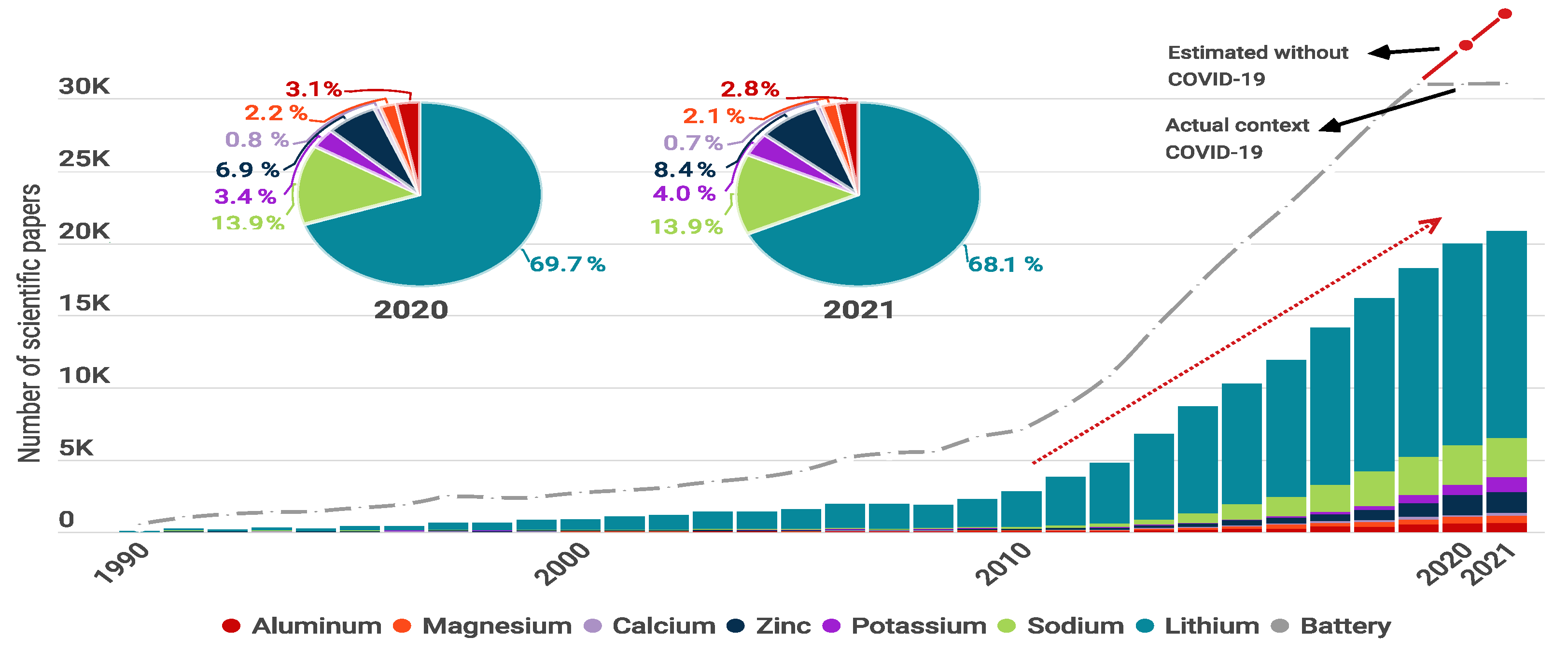
Figure 2.
Illustration of the crucial internal components of a battery, showing different types of materials researched for cathodes, anodes, electrolytes, and separators. Arrows indicate the flow of electrons (through the external circuit) and ions (through the electrolyte) during the charging (red) and discharging (blue) process. Graph constructed by the authors.

Figure 3.
Typical battery configurations. Flexible: 1D, 2D, and 3D. Rigid: coin, cylindrical, prismatic, and pouch. Graph constructed by the authors.
Figure 3.
Typical battery configurations. Flexible: 1D, 2D, and 3D. Rigid: coin, cylindrical, prismatic, and pouch. Graph constructed by the authors.

Figure 4.
Elements used in battery manufacturing organized from low to high availability. The first column represents the abundance in the earth’s crust. The second shows the cost per 100 g of the pure element. The third represents the Young modulus. The fourth shows the electrical conductivity. The length of the bars is normalized between the lowest and highest value for each parameter. The * symbol indicates that there is no value. Graph constructed by the authors. Data from Chemicool.com.

Figure 5.
Geographical distribution of mineral resources vs. battery manufacturing companies. (A) Countries with mineral resources, (B) countries with mineral resources and manufacturing companies, and (C) manufacturing countries. Note: the length of the bar indicates the relative fraction of the total production. Graph constructed by the authors. Data from US Geological Survey, Mineral Commodity Summaries 2020.

Figure 6.
Publications per year about negative electrodes, comparing seven battery types: Li, Na, K, Zn, Ca, Mg, and Al. Graph constructed by the authors. Data from Web of Science.
Figure 6.
Publications per year about negative electrodes, comparing seven battery types: Li, Na, K, Zn, Ca, Mg, and Al. Graph constructed by the authors. Data from Web of Science.

Figure 7.
Current research in anode materials. Columns organize the seven battery types. Rows represent the composite material group. Theoretical capacity, experimental capacity, current density, and the number of cycles are also included. A special symbol highlights flexible anode materials. Graph constructed by the authors from references in Table 2, Table 3, Table 4, Table 5, Table 6 and Table 7.

Figure 8.
The advance of the anodes’ experimental specific capacity, comparing the seven battery types: Li, Na, K, Zn, Ca, Mg, and Al. Continuous line: traditional intercalation materials. Dot lines conversion materials. Graph constructed by the authors from references in Table 2, Table 3, Table 4, Table 5, Table 6 and Table 7. NW, nanowires; NR, nanorods; NB, nanobelts.

Figure 9.
Publications per year about positive electrodes, comparing seven battery types: Li, Na, K, Zn, Ca, Mg, and Al. Graph constructed by the authors. Data from Web of Science.
Figure 9.
Publications per year about positive electrodes, comparing seven battery types: Li, Na, K, Zn, Ca, Mg, and Al. Graph constructed by the authors. Data from Web of Science.

Figure 10.
Current research in cathode materials. Columns organize the seven battery types. Rows represent the composite material group. Theoretical capacity, experimental capacity, current density, and the number of cycles are also included. A special symbol highlights flexible anode materials. Graph constructed by the authors from references in Table 8, Table 9, Table 10, Table 11, Table 12, Table 13 and Table 14.

Figure 11.
The advance of the cathodes’ specific capacity, comparing the seven battery types: Li, Na, K, Zn, Ca, Mg, and Al. Continuous line: traditional intercalation materials. Dot lines conversion materials. Graph constructed by the authors from references in Table 8, Table 9, Table 10, Table 11, Table 12, Table 13 and Table 14. NW, nanowires; NR, nanorods; NB, nanobelts.

Figure 12.
Critical characteristics of separator materials and their general classification. Graph constructed by the authors.
Figure 12.
Critical characteristics of separator materials and their general classification. Graph constructed by the authors.

Figure 13.
Current and future battery applications in daily life, including health monitoring, communication, transportation, entertainment, working, lighting, cleaning, and so on. Graph constructed by the authors.
Figure 13.
Current and future battery applications in daily life, including health monitoring, communication, transportation, entertainment, working, lighting, cleaning, and so on. Graph constructed by the authors.

Figure 14.
Graph constructed by the authors from Gartner hype cycle for promising anodes materials for batteries. Materials are grouped according to the seven battery types: Li, Na, K, Zn, Ca, Mg, and Al. Each material is organized into a stage according to the estimation of development among innovation and productivity stage.

Figure 15.
Graph constructed by the authors from Gartner hype cycle for promising cathode materials for batteries. Materials are grouped according to the seven battery types: Li, Na, K, Zn, Ca, Mg, and Al. Each material is organized into a stage according to the estimation of development among innovation and productivity stages.
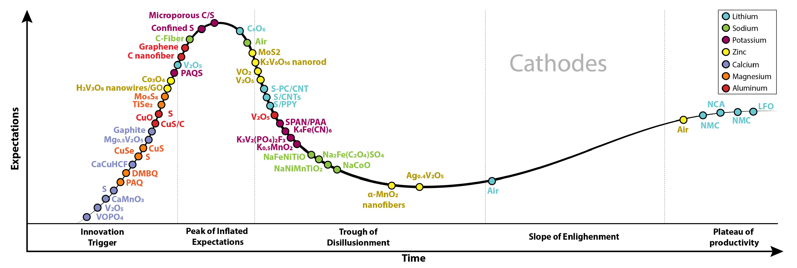
| Parameter | Symbol | Unit | Description |
|---|---|---|---|
| Voltage | V | Cell voltage is cathode potential minus anode potential. | |
| Capacity | Ct | The maximum electrical charge stored in the cell. | |
| Specific Capacity | Cs | kg−1 | The capacity of electrodes is usually provided per mass of active material. |
| Energy | E | Maximum energy delivered by a given system with a theoretical voltage and a theoretical capacity: . | |
| Specific Energy | Es | /kg−1 | Maximum energy of a cell permass of the whole battery:. |
| Energy Density | Ed | W h L−1 | Nominal battery energy per unit volumeof the whole battery:. |
| Coulombic Efficiency | % | Ratio of discharging and charging capacity. . | |
| C-rate | C | - | Measure for the charging/discharging current of an electrochemical cell. A C-rate of 1 corresponds to a full charge/discharge within 1 h. . |
| Current Density | J | m−2 | Electric current per cross-sectional area. |
| Cycle Life | - | - | Cycle numbers. |
Table 2.
Anode materials for Li-based batteries.
| Anode Material | Voltage Range (V) | Specific Capacity (mA h g) | Current (mA g) | Cycles | |
|---|---|---|---|---|---|
| Intercalation | |||||
| Graphite [88] | 449 | 0.1 a | 100 | ||
| Porous Hard Carbon [79] | 503 | 0.2 a | |||
| UF layerd Graphite [80] | 0.1–2.0 | 393 | 40 | 800 | |
| LiTiO NP/CNTs [89] | 1.2–2.0 | 173 | 0.1 a | 1000 | 98.5 |
| TiO [90] | 0.8 | 330 | |||
| TiO/CNT [91] | 316 | 66 | 100 | ||
| TiO/G [92] | 272 | 168 | 100 | ||
| Alloy | |||||
| Ge [93] | 0.02–1.2 | 1300 | 250 | 340 | 60 |
| GeO/GO [85] | 0–2.5 | 1000 | 250 | 50 | 69 |
| Li–B [86] | 213.2 | 200 | |||
| Li–B–Al [86] | 211.9 | 100 | 200 | 83.9 | |
| Li–Mg [94] | 607 | 50 | 200 | ||
| Si MW [81] | 3038 | 400 | 200 | 90 | |
| Si/C film [82] | 0.1–2.5 | 2276 | 8400 | 150 | 73 |
| Si/C [95] | 3500 | 12,600 | 300 | ||
| Si NP/CNTs [96] | 1629 | 200 | 200 | ||
| Sn NP/G [97] | 1022 | 2000 | 1000 | ||
| SnO NC/G [98] | 1865 | 500 | 500 | ||
| Sn/SnO/G | 0.01–3.0 | 2970 | 100 | 75 | 44 |
| ZnCoO/rGO | 1613 | 500 | 400 | ||
| Conversion | |||||
| CoO/rGO | 0.01–3.0 | 2313 | 100 | 500 | 74 |
| CoSe NS/G | 680 | 50 | 300 | ||
| CuMnO/G | 0.01–3.0 | 1491 | 50 | 150 | 75 |
| GaS NF/CNTs [99] | 2118 | 120 | 100 |
a: C-rate. CNT: carbon nanotubes, G: graphene, GO: graphene Oxide, NC: nanocrystals, NF: nanofilms, NP:
nanoparticles, NS: nanosheets, NW: nanowires, UF: ultrafine.
Table 3.
Anode materials for Na-based batteries.
| Anode Material | Voltage Range (V) | Capacity (mA h g) | Current (mA g) | Cycles | |
|---|---|---|---|---|---|
| Alloy | |||||
| Si | 279 | 10 | 100 | ||
| Intercalation | |||||
| Hard carbon [103] | ∼0.0–3.0 | 250 | 1000 | 1200 | |
| crumpled G [119] | ∼0.0–2.5 | 125 | 1000 | 500 | |
| porous G/SbO [120] | ∼0.0–3.0 | 350 | 50 | 100 | |
| porous multilayered G [121] | ∼0.0–3.0 | 392 | 100 | 100 | |
| G/CoSe nanosheets [122] | ∼0.0–2.5 | 180.7 | 500 | 100 | |
| G nanosheets/FeO [123] | ∼0.0–3.0 | 400 | 100 | 200 | |
| G/P stacks [124] | 0.0–2.0 | 1706 | 260 | 60 | |
| G/SnS stacks [125] | ∼0.0–2.5 | 618.9 | 200 | 100 | |
| G/TiNbO [126] | ∼0.0–3.0 | 200 | 200 | 70 | |
| N-doped G sheets [127] | ∼0.0–3.0 | 115.5 | 50 | 260 | |
| N-doped G/NaTi(PO) [128] | ∼1.5–3.0 | 75 | 20 a | 200 | |
| N-rich G [129] | ∼0.0–3.0 | 250 | 50 | 250 | |
| N-/S-doped G sheets [130] | ∼0.0–3.0 | 289 | 100 | 100 | |
| 2D TiO/TiS [105] | 0.1–3.0 | 329.63 | 1000 | 140 | |
| Phosphorene | |||||
| Black P/C [131] | ∼0.0–3.0 [132] | 958 [132] | 2000 | 500 | 58.5 |
| CuP–C [114] | ∼0.0–3.0 | 378.9 | 1000 | 1000 | 89 |
| P/C-amorphous [133] | ∼0.0–2.0 | 1764 | 250 | 140 | 87 |
| P-layered black [134] | 0.0–2.0 | 1500 | 125 | 25 | |
| P/C composite layers [135] | ∼0.0–1.5 | 1500 | 100 | 100 | |
| P/G hybrid [136] | 0.0–1.5 | 2400 | 0.02 C | 100 | |
| P-PMCNFs [113] | ∼0.0–2.0 | 2260 | 100 | 90 | 70 |
| P-C [111] | 1308 | 200 | |||
| P-TBMC [116] | ∼0.0–2.0 | 1544 | 8000 | 800 | 69.8 |
| VP/P [115] | ∼0.0–2.0 | 738 | 8000 | 100 | 85.9 |
| TMS | |||||
| MoS nanosheets [137] | ∼0.0–3.0 | 386 | 40 | 100 | |
| MoS/C nanosheets [138] | ∼0.0–2.9 | 280 | 1 C | 300 | |
| MoS/G sheets [139] | 0.1–2.3 | 218 | 25 | 20 | |
| MoSe nanoplates [140] | 0.1–3.0 | 369 | 0.1 C | 50 | |
| WSe [141] | 0.1–2.5 | 117 | 0.1 C | 30 | |
| WSe/C [142] | ∼0.0–3.0 | 270 | 0.2 C | 50 | |
| MoS/G Carbon [118] | 0.5–3.2 | 310 | 5000 | 2500 |
a: C-rate. C: carbon, G: graphene, NF: nanofibers, P: phosphorus PMCNFs: porous multichannel flexible
freestanding, carbon nanofibers.
Table 4.
Anode materials for K-based batteries.
| Anode Material | Voltage Range (V) | Capacity (mA h g) | Current (mA g) | Cycles | |
|---|---|---|---|---|---|
| Alloy | |||||
| CoO–FeO/C [150] | 0.01–3.0 | 770 | 1000 | 50 | 54 |
| CoS–G [151] | 0.01–2.9 | 434.5 | 4 a | 64.4 | |
| KTiO [147,152] | 0.01–3.0 | 151 | 500 | 900 | 65.4 [148] |
| KTi(PO)/C [153] | 1.2–2.8 | 75.6 | 5 a | 75 | |
| MoS [154] | 0.5–2.0 | 98 | 2.86 a | 74.4 | |
| MoS–RGO [155] | 0.01–3.0 | 679 | 500 | 30 | |
| SbS–S [156] | 0.1–3.0 | 548 | 1000 | 69.7 | |
| Sb NP/3D C [157] | 0.01–2.0 | 478 | 1000 | 68.2 | |
| SnO–G–C [158] | 0–2.5 | 519 | 1000 | 100 | 44 |
| SnP/C fiber [159] | 0.1–2.0 | 514 | 2000 | 200 | 64 |
| SnP/C [160] | 0.01–2.0 | 697 | 1200 | 50 | 58 |
| SnS/RGO [161] | 0.01–2.0 | 355 | 2000 | 56 | |
| TiC [162] | 0.01–3.0 | 136 | 300 | 27 | |
| TiCNT [163] | 0.01–3.0 | 710 | 28.40 | ||
| TiSe [164] | 1.0–3.0 | 92.7 | 1000 | 67.1 | |
| VSe [165] | 0.01–2.6 | 366 | 2000 | 69.10 | |
| Carbon | |||||
| Graphite [144] | 0.01–1.5 | 273 | 200 [166] | 200 [167] | 87 [168] |
| expanded Graphite [145] | 0.01–3.0 | 267 | 200 | 500 | 81 |
| hard Carbon [169] | 0.01–1.5 [146] | 300 | 1395 | 100 | 87 |
| soft Carbon [144] | 273 | 50 | 50 | ||
| Organic | |||||
| KPC [170] | 0.1–2.0 | 245 | 2 a | 44 | |
| KTP [171] | 0.1–2.0 | 305.8 | 1000 | 76.1 |
a: C-rate. C: carbon, CNT: carbon nanotubes, G: graphene, K2PC: potassium 2,5-pyridinedicarboxylate,
K2TP:dipotassium terephthalate, P: phosphorous, RGO: reduce graphene oxide.
Table 5.
Anode materials for Zn-based batteries.
| Anode Material | Voltage Range (V) | Capacity (mA h g) | Current (mA g) | Cycles | |
|---|---|---|---|---|---|
| Carbon-coated ZnO [175] | 1.5–2.0 | 155.5 | 1 | 42 | 48.8 |
| hyper dendritic Zn [177] | 232.6 | 0.2 | 100 | 77 | |
| Zn sponge [176] | 0.9–2.2 | 164 | 0.03 | 36 | |
| Zn on Cu foam [178] | 690 | 25.4 | 9000 | 31 | |
| Zn foil with IL membrane [179] | 0.8–2.3 | 107 | |||
| ZnO–Ag–polypyrrole [180] | 1.2–1.9 | 437 | 1 | 300 | 87.5 |
| Zn foil [181] | 0.4 | 0.06 | 147 | 100 | |
| ZnO [182] | 269.8 | 0.5 | 1000 | 100 | |
| ZnO/C [183] | 1.2–2.0 | 266.7 | 0.17 | 400 | |
| ZnO with ionomer layer [184] | 1.0–1.9 | 124.5 | 0.78 | 67 | 75 |
| ZnO in Carbon matrix [174] | 1.4–2.0 | 241.9 | 4.96 | 150 | 82.2 |
| Zn sponge advanced [185] | 1.4–1.9 | 310 | 3.1 | 141 | 96.6 |
Table 6.
Anode materials for Ca-based batteries.
| Anode Material | Voltage Range (V) | Capacity (mA h g) | Current (mA g) | Cycles | |
|---|---|---|---|---|---|
| Alloy | |||||
| Ca [50] | 30 | 85 | |||
| Ca-Si [188] | 0.37 | 240 | 1 | ||
| Ca-Sn [192] | 0.8 | 526 | 350 [189] | 80 | |
| Carbon | |||||
| Graphene [193] | 225 | ||||
| MCMB [187] | 4.6 | 62 | 1 a | 300 | 82 |
| Organic | |||||
| PANI [190] | 0.4 | 114 | 150 | 200 | 99 |
| PNDIE [191] | −0.45 | 160 | 915 | 4000 | 99 |
| PTCDA [194] | 80 |
a: C-rate. CC: carbon cloth, MCMB: mesocarbon microbead, PANI: polyaniline, PNDIE: polyimide, polynaphthalenetetracarboxiimide,
PTCDA: perylenetetracarboxylic dianhydride.
Table 7.
Anode materials for Mg-based batteries.
| Anode Material | Voltage Range (V) | Capacity (mA h g) | Current (mA g) | Cycles | |
|---|---|---|---|---|---|
| MgBi [198] | 0.23 | 257 | 385 | 100 | 86 |
| MgBi NT [199] | 350 | 19 | 200 | 95 | |
| BiSb [198] | 298 | 1 a | 100 | 75 | |
| In [201] | 0.09 | 425 | 0.01 a | ||
| LTO [196] | 175 | 15 | 500 | ||
| Sb [198] | 16 | 1 a | 50 | ||
| SnSb [200] | 420 | 50 | 200 |
a: C-rate. LTO: Li4Ti5O12, NT: nanotubes.
Table 8.
Cathode materials for Li-based batteries.
| Cathode Material | Voltage Range (V) | Capacity (mA h g) | Current (mA g) | Cycles | Retention (%) |
|---|---|---|---|---|---|
| LiCoO [208] | 3–4.6 | 220 | C/4 * | 100 | |
| LiFePO4/C/V2O3 [225] | 3.4 | 140 | 750 | 30 | 100 |
| LiFePO4/CNTs [210] | 115 | 1700 | 1000 | 98 | |
| LiFePO4/G [226] | 123 | 1700 | 1000 | 89 | |
| CNT/LiNi0.5Mn1.5O4 [227] | 140 | 70 | 100 | 96 | |
| LiMn2O4 | 80 | ||||
| CNT/LiNi0.8Co0.15Al0.05O2 [211] | 189 | 50 | 60 | 96 | |
| LiCo1/3 Ni1/3Mn1/3O2 [228] | 4.6 | 158 | 30 | 99 | |
| LiNixFeyAlzO2 [212] | 3–4.5 | 200 | 1 * | 100 | 80 |
| V2O5/CNTs [229] | 298 | 150 | 200 | 71 | |
| PDHBQS-SWCNTs [222] | 1.5–3.5 | 182 | 5000 | 500 | 89 |
| Sulfur | |||||
| S coating on | |||||
| hydroxylated CNTs [230] | 1274 | 100 | 57 | ||
| S encapsulated in spherical CNTs particles [220] | 1.5–2.8 | 1343 | 3344 | 100 | 70 |
| S encapsulated in CNTs [219] | 1.5–3 | 1485 | 3344 | 400 | 60 |
| S embedded in CNT foam [221] | 1379 | 1672 | 200 | 76 | |
| S wrapped on CNT array [231] | 1092 | 50 | 64 | ||
| S wrapped on CNTs [232] | 1065 | 300 | 77 | ||
| ZrB2−S [223] | 1243 | 5 * | 600 | 89 |
*: C-rate, CNT: carbon nanotubes, G: graphene, PDHBQS: poly-dihydroxyl-benzoquinonyl sulfide, SWCNTs:
single-wall carbon nanotubes, S: sulfur.
Table 9.
Cathode materials for Na-based batteries.
| Cathode Material | Voltage Range (V) | Capacity (mA h g) | Current (mA g) | Cycles | Retention (%) |
|---|---|---|---|---|---|
| Layer metal oxides | |||||
| O3-NaNi0.5Mn0.5O2 [242] | 2.0–4.0 | 133 | 468 | 500 | 70 |
| O3-NaNi0.12Cu0.12Mg0.12Fe0.15 Co0.15Mn0.1Ti0.1Sn0.1Sb0.04O2 [243] | 2.0–3.9 | 110 | 360 | 500 | 83 |
| −NaMnO2 [237] | 2.0–3.8 | 175 | 10 | 50 | |
| −NaMnO2 [237] | 2.0–3.8 | 130 | 10 | 50 | |
| P2−Na2/3Ni1/3Mn1/3Ti1/3O2 [236] | 2.5–4.1 | 88 | 1 a | 500 | 83.9 |
| NaNi0.5Mn0.2Ti0.3O2 [244] | 2.8 | 135 | 240 | 200 | 85 |
| Na3Ni1.5Cu0.5BiO6 [245] | 3.2 | 94 | 10.8 | 200 | 62 |
| NaNi0.5Mn0.5O2 CNT [235] | 2.5 | 141 | 12 | 100 | 90 |
| Na0.67[Mn0.6Ni0.1Fe0.3]O [246] | 4.3 | 200 | 13 | 25 | 75 |
| Na0.7CoO2 Microspheres [247] | 2.9 | 125 | 5 | 300 | 86 |
| Na0.67[Fe0.5Mn0.5]O2 [234] | 2.7 | 183 | 15 | 10 | 90 |
| Na0.9Cu0.22Fe0.3Mn0.48O2 [248] | 3.2 | 100 | 10 | 100 | |
| NaNi1/3Fe1/3Mn1/3O2 [249] | 123 | 130 | 100 | 80 | |
| Na0.67Mn0.67Ni0.28Mg0.05O2 [250] | 123 | 0.1 a | |||
| Na2/3Ni1/3Mn1/3Ti1/3O2 [236] | 88 | 17.3 | 500 | 83 | |
| HD−TiO2−N−RGO [241] | 203.4 | 100 | 100 | 91 | |
| Prussian blue | |||||
| NaxNi0.1Mn0.9Fe− (CN)6·nH2O [240] | 110 | 1000 | 95 | ||
| Prussian white | |||||
| Na1.92FeFe(CN)6 [251] | 3 | 150 | 600 | 1000 | 75 |
| Polyanionic Compoound | |||||
| Na2Fe(C2 O4)SO4 ·H2O [238] | 1.7–4.2 | ~75 | 44 | 500 | 85 |
| Na3V2(PO4)2F3 [252] | 3.7 | 120 | 0.05 a | ||
| Na2Fe(C2O4)SO4 [238] | 3.1 | 170 | 44 | 500 | 85 |
| Sulfur | |||||
| S sugar derived [253] | 0.8–2.6 | 700 | 1675 | 1500 | 81 |
| S/Fe–HC [254] | 0.8–2.7 | 1023 | 100 | 1000 | 38 |
a: C-Rate. HD: highly dense, RGO: reduced graphene oxide.
Table 10.
Cathode materials for K-based batteries.
| Cathode Material | Voltage (V) | Capacity (mA h g) | Current (mA g) | Cycles | Retention (%) |
|---|---|---|---|---|---|
| Transition metal Oxide | |||||
| NaCoO2 [271] | 2.9 | 80 | 0.05 a | 50 | 80 |
| NaCrO [272] | 2.95 | 88 | 0.05 a | 200 | 71 |
| K0.6CoO2 [273] | 3 | 82 | 11.8 | 300 | 87 |
| K0−3CrF6 | 5.43 | 284 | |||
| KFMO [274] | 2.45 [275] | 178 | 1000 | 300 | 87 |
| K0.3MnO2 [256] | 1.5–3.5 | 136 | 27.9 | 685 | 91 |
| K0.5MnO2 [257] | 3.6 | 140 | 20 | 50 | 76 |
| KNiCoMnO [276] | 3.1 | 76.5 | 20 | 100 | 87 |
| K0.5V2O5 [277] | 2.5 | 90 | 10 | 250 | 81 |
| Prussian blue analogue | |||||
| KCuFe(CN)6 [278] | 60 | 83 a | 83 | ||
| K4Fe(CN)6 [279] | 3.6 | 65.9 | 20 | 400 | 68 |
| KFeFe(CN)6 | 3.75 [280] | 122 [262] | 100 [281] | 1000 [281] | 90 [280] |
| KMnFe(CN)6 [263] | 3.9 [282] | 142 | 10 a [262] | 100 | 96 |
| KNiFe(CN)6 [283] | 59 | 41 a | 95 | ||
| SWCNT−PB [284] | 1000 | 80 | |||
| MWCNT−PB [284] | 1000 | 60 | |||
| RGO−PB−SSM [285] | 90 | 10 a | 87 | ||
| Polyanionic compounds | |||||
| FePO4 | 2.1 | 160 | 4 | 50 | |
| FeSO4F | 3.5 | 0.05 a | |||
| KVPO4F [259] | 4 | 92 | 665 | 50 | 97 |
| KVP2O7 [260] | 4.4 | 60 | 20 a | 100 | 83 |
| K3V2(PO4)2F3 [261] | 3.7 | 104 | 250 | 100 | 97 |
| K3V2(PO4)3/C [286] | 3.6 | 54 | 20 | 100 | |
| Organic | |||||
| Anthraquinone [264] | 1.7 | 114 | 13 | 100 | |
| K2C6O6 [265] | 1.7 | 213 | 1 a | 100 | |
| PAQS [267] | 2.4 | 200 | 50 | 300 | 80 |
| PTCDA [287] | 2.1 | 130 | 13 | 50 | |
| Sulfur | |||||
| Catholyte: S + K2Sx [288] | 402 | 1 | 1000 | 100 | |
| Confined and covalent S [269] | 873.9 | 100 | 300 | 86.3 | |
| CMK-3/S [289] | 606 | 10 | 10 | 40 | |
| S-CNT [290] | 1140 | 167.5 | 50 | 52.6 | |
| Microporous C/S [270] | 1198.3 | 20 | 150 | 72.5 | |
| Pyrolyzed poly acrylonitrile/S [268] | 0.8–2.9 | 710 | 125 | 100 | 54 |
| Sulfurized Carbonized polyacrylonitrile [291] | 1050 | 837.5 | 100 | 95 | |
a: C-rate. CNT: carbon nanotubes.
Table 11.
Cathode materials for Zn-based batteries.
| Cathode Material | Voltage Range (V) | Capacity (mA h g) | Current (mA g) | Cycles | Retention (%) |
|---|---|---|---|---|---|
| Layered Oxides | |||||
| Manganese | |||||
| −MnO2 nanorods [304] | 115.9 | 5000 | 4000 | 97.7 | |
| −MnO2 nanofibers [305] | 285 | 1520 | 5000 | 92 | |
| −MnO2/rGO [306] | 382 | 300 | 3000 | 94 | |
| MnO2 [307] | 70 | 1885 | 10,000 | ||
| MnO2−PANI [308] | 125 | 2000 | 5000 | ||
| Vanadium | |||||
| H2V3O8 nanowires [309] | 0.2–1.6 | 173.6 | 5000 | 1000 | 94.3 |
| H2V3O8 nanowires/ GO [297] | 0.2–1.6 | 394 | 300 | 2000 | 87 |
| Li−V2O5·nH2O [310] | 0.4–1.4 | 192 | 10,000 | 1000 | |
| LiV3O8 [311] | 0.6–1.2 | 140 | 133 | 65 | |
| Mg0.1V2O5 · H2O (MgVO) | 0.1-1.6 | 470 | 5000 | 3000 | 95 |
| Bilayer V2O5 · nH2O [293] | 0.2–1.6 | 200 | 6000 | 900 | 71 |
| VO [295] | 0.7–1.7 | 133 | 10,000 | 10,000 | 79 |
| VO (B) [296] | 0.3–1.5 | 357 | 100 | 50 | |
| VO [312] | 0.2–1.6 | 372 | 5000 | 4000 | 91.1 |
| V6O13 [313] | 0.2–1.5 | 240 | 4000 | 2000 | 92 |
| V3O7 · H2O/rGO [314] | 0.3–1.5 | 245 | 1500 | 1000 | 79 |
| VO2/rGO [315] | 0.3–1.3 | 240 | 4000 | 1000 | 99 |
| VS2 flake [316] | 0.4–1.0 | 125 | 200 | 250 | 99.7 |
| Zn0.25V2O5 · nH2O nanobelts [317] | 0.5–1.4 | 260 | 2400 | 1000 | 80 |
| others | |||||
| Ag0.4V2O5 [318] | 0.4–1.4 | 144 | 20 | 4000 | |
| Ca0.25V2O5 · nH2O [319] | 0.6–1.6 | 70 | 20 | 3000 | 96 |
| K2V6O16·2·7H2O nanorod [320] | 0.4–1.4 | 188 | 6 | 500 | 82 |
| Na0.33V2O5 [321] | 0.2–1.6 | 218.4 | 1 | 1000 | 93 |
| NaV3O8 [322] | 0.3–1.25 | 165 | 4 | 1000 | 82 |
| Na2V6O16·1·63H2O [323] | 0.2–1.6 | 158 | 5 | 6000 | 90 |
| Na1.1V3O7.9/rGO [324] | 0.4–1.4 | 171 | 300 | 100 | |
| NH4V4O10 [325] | 0.4–1.4 | 255.5 | 10 | 1000 | |
| MoO2/Mo2N nanobelts [326] | 0.25–1.35 | 113 | 1 | 1000 | 78.8 |
| MoS [327] | 0.3–1.5 | 161.7 | 1 | 1000 | 97.7 |
| Prussian blue analogues | |||||
| CuHCF [299] | 0.45–1.4 | 50 | 10,000 | 1000 [328] | 80 |
| ZnHCF [329] | 0.8–1.9 | 68 | 300 | 200 | 85 |
| Polyanionic compound | |||||
| Li3V2(PO4)3 [301] | 0.7–2.1 | 113.5 | 1500 [294] | ||
| Na3V2(PO4)3/C [302] | 0.8–1.7 | 97 | 50 | 200 [330] | 74 |
| Na3V2(PO4)2F3 [303] | 0.8–1.9 | 50 | 1000 | ||
| Organic | |||||
| Polyaniline [53] | 0.5–1.5 | 82 | 5000 | ||
| Quinones [331] | 0.2–1.8 | 120 | 500 | 3000 | 92 |
Table 12.
Cathode materials for Ca-based batteries.
| Cathode Material | Voltage Range (V) | Capacity (mA h g) | Current (mA g) | Cycles | Retention (%) |
|---|---|---|---|---|---|
| Carbon | |||||
| Graphite [189] | 4.45 | 70 | 350 | 95 | |
| Layered Oxide | |||||
| CaCoO [334] | 3 | 150 | 30 | ||
| MoO [337] | 1.3 | 180 | 2 | 12 | |
| VO [338] | 3.2 | 465 | 200 [340] | 200 [340] | |
| Layered sulfide | |||||
| TiS [335] | 1.5 | 520 | 1/50 a | 1 | |
| S/meso -C [341] | 0.75 | 600 | |||
| Polyanionic compound | |||||
| VOPO4·2H2O [340] | 2.8 | 100 | 200 | 200 | |
| Prussian blue analogue | |||||
| K2BaFe(CN)6 | 0–0.8 | 55.8 | 100 | ||
| Na0.2MnFe(CN)6 [336] | 0–3.5 | 70 | 35 | ||
| Organic | |||||
| CaCuHCF [190] | 50 | 300 | 1000 | 95 | |
a: C-rate. PANI: polyaniline, PAQS: polyanthraquinonyl sulfide, PTCDA: perylene-tetracarboxylicaciddianhydride,
NB: nanobelts, NF: nanofibers, NR: nanorod, NW: nanowires.
Table 13.
Cathode materials for Mg-based batteries.
| Cathode Material | Voltage Range (V) | Capacity (mA h g) | Current (mA g) | Cycles | Retention (%) |
|---|---|---|---|---|---|
| Intercalation | |||||
| Mo6S8 [342] | 1.3 | 122 | 15 a | 3000 | 93 |
| MoO [344] | 1.8 | 210 | |||
| MoOF [345] | 70 | ||||
| MoVO [346] | 2.1 | 235 | |||
| TiS [347] | 1.2 | 200 | 0.2 a | 40 | |
| TiS [348] | 1.5 | 158 | 24 | 400 | 95 |
| TiS [349,350] | 1.2 | 83.7 | 10 | 50 | |
| TiSe [351] | 1 | 110 | 5 | 50 | |
| VO [352] | 2.56 | 150 | |||
| VSe [351] | 1 | 110 | |||
| Polianionic compound | |||||
| AgCl [353] | 2 | 178 | 930 | 100 | |
| CuS [354,355] | 1.6 | 200 | 50 | 30 | |
| Cu2Se [356] | 1.2 | 230 | 5 | 35 | |
| FePO4 [357] | 2 | 15 | 20 | ||
| MnO2 [358] | 2 | 150 | |||
| Silicate [359] | 4 | ||||
| Organic | |||||
| DMBQ [360] | 2 | 100 | 0.2 a | 30 | |
| PAQ [361] | 1.7 | 150 | 130 | 100 | |
| Sulphur | |||||
| S [362] | 1.77 | 600 | 200 | 100 | |
| S-ACCS [363] | 1.5 | 950 | 100 | 48 | |
| S-C [364] | 1.1 | 1081 | 30 | 76 | |
| S-CMK [365] | 1.6 | 800 | 100 [366] | 50 [366] | |
| S-CNT [367] | 1.3 | 1200 | 100 | 83 | |
| S-rGO [368] | 1.5 | 1028 | 50 | 21 | |
| Oxygen | |||||
| O [369,370] | 2.9 | 1300 | |||
| I [371] | 2 | 200 | |||
a: C-rate, CNT: carbon nanotubes, DMBQ: dimethoxy-1,4-benzoquinone, PAQ: olyanthraquinone.
Table 14.
Cathode materials for Al-based batteries.
| Cathode Material | Voltage (V) | Capacity (mA h g) | Current (mA g) | Cycles | Retention (%) |
|---|---|---|---|---|---|
| Carbon | |||||
| 3D graphitic foams [374] | 1.8 | 60 | 12,000 | 7500 [373] | 100 |
| C paper [372] | 1.8 | 85 | 50 | ||
| C NF [376] | 126 | 1000 | 20,000 | 100 | |
| C nanoscrolls [376] | 104 | 1000 | 55,000 | 100 | |
| Defect-free G [375] | 1.94 | 100 | 5000 | 25,000 | 97 |
| G film [384] | 2.3 | 240 [385] | 6000 | 250,000 | 91.7 |
| G microflower [386] | 1.85 | 92 | 100 | 5000 | 100 |
| G nanoribbons [387] | 2 | 148 | 2000 | 10,000 | 98 |
| kish Graphite flakes [388] | 1.79 | 142 | 50 | 200 | 100 |
| mesoporous rGO [389] | 120 | 20 | 100 | 85 | |
| Zeolite-templated C [390] | 1.05 | 382 | 50 | 1000 | 86 |
| Metal Oxides | |||||
| Li3VO4/C [377] | 0.5 | 137 | 20 | 100 | 35 |
| MoO [378] | 1.95 | 90 | 100 | 100 | 28 |
| Mo2,5+yVO9+x [391] | 0.75 | 340 | 2 | 25 | 70 |
| VO [392] | 0.5 | 116 | 50 | 100 | 70 |
| VO [393] | 0.6 | 239 | 44.2 | ||
| VO/C [394] | 1 | 200 | 10 | 15 | 66 |
| VO nanowires [49] | 0.55 | 305 | 20 | 78 | |
| Metal sulfide | |||||
| CuS/C MS [379] | 1 | 90 | 20 | 100 | 32 |
| Cu0,31Ti2S4 [380] | 95 | 5 | 50 | 16 | |
| Hexagonal NiS NB [395] | 0.9 | 105 | 20 | 100 | 100 |
| Ni3S2/G [396] | 1 | 350 | 100 | 100 | 17 |
| Porous CuO MS [381] | 0.6 | 250 | 50 | 100 | 45 |
| Mo6S8 [397] | 80 | 6 | 50 | 47 | |
| SnS2/rGO [398] | 0.68 | 392 | 100 | 100 | 25 |
| Sn porous film [399] | 1.1 | 406 | 20 | 100 | 91 |
| TiS [380] | 50 | 5 | 50 | 72 | |
| VS4/rGO [399] | 407 | 100 | 100 | 20 | |
| Sulfur | |||||
| S/ACC [400] | 0.75 | 1320 | 500 | 20 | |
| S/CNF [382] | 0.76 | 600 | 21 | 20 | |
| S/mesoporous C [383] | 0.5 | 400 | 251 | ||
| S powder [401] | 1.2 | 1300 | 50 | 20 |
ACC: Activate Carbon cloth, C: Carbon, CNT: Carbon, nanofiber, G: Graphene, MS: microsphere, NB: Nanobelts,
NF: Nanofibers.
Table 15.
Liquid electrolyte solvents.
| Cyclic Carbonates | Organic Fluorinated Carbonates | Sulfones | Ionic Liquid |
|---|---|---|---|
| ACN | MFAa | EMSa | EMI |
| −BL | FPCa | TMS | DMPI |
| DEC | EMSa | FS | DEDMI |
| DMC | TFPMSa | BS | TMHE |
| DME | GLNb | EVS | PYR |
| DMF | ADNc | ADN | PIP |
| DMSO | SENa | DMMP | MORP |
| EC | TMMP | TFSI | |
| EMC | BC | BETI | |
| MF | FSI | ||
| NM | TSAC | ||
| PC | FSA− | ||
| THF | TFSA− | ||
| VC | BF4− | ||
| diglyme | PF6− | ||
| tetraglyme | N(CN)2− | ||
| DGM | [BH4]− | ||
| UREA | PEGylated |
Table 16.
Salts for electrolytes.
| Li | Na | K | Zn | Ca | Mg | Al |
|---|---|---|---|---|---|---|
| LiTFSI | NaTFSI | KFTFSI | Zn(TFSI)2 | Ca(TFSI)2 | MgTSFI2 | AlCl4 |
| LiClO4 | NaClO4 | KClO4 | Zn(ClO4)2 | CA(ClO4)2 | MgCl | |
| LiBOB | NaBOB | KPF6 | Zn(CF3SO3)2 | Ca(PF6)2 | Mg(CB11H12)2 | |
| LiPF6 | NaPF6 | KBF4 | ZnSO4 | Ca(BF4)2 | Mg(BBu2Ph2)2 | |
| LiBF4 | NaBF4 | KFSI | Ca(NO3)2 | Mg[B(HFIP)4]2 | ||
| LiAsF6 | NaFSI | KCF3SO3 | Ca(BH4)2 | Mg(BH) | ||
| LiOSO2CF3 | NaFTFSI | |||||
| NaOTf | ||||||
| NaDFOB |
Publisher’s Note: MDPI stays neutral with regard to jurisdictional claims in published maps and institutional affiliations. |
© 2022 by the authors. Licensee MDPI, Basel, Switzerland. This article is an open access article distributed under the terms and conditions of the Creative Commons Attribution (CC BY) license (https://creativecommons.org/licenses/by/4.0/).
Share and Cite
MDPI and ACS Style
Pantoja, W.; Perez-Taborda, J.A.; Avila, A. Tug-of-War in the Selection of Materials for Battery Technologies. Batteries 2022, 8, 105. https://doi.org/10.3390/batteries8090105
AMA Style
Pantoja W, Perez-Taborda JA, Avila A. Tug-of-War in the Selection of Materials for Battery Technologies. Batteries. 2022; 8(9):105. https://doi.org/10.3390/batteries8090105
Chicago/Turabian StylePantoja, Wendy, Jaime Andres Perez-Taborda, and Alba Avila. 2022. "Tug-of-War in the Selection of Materials for Battery Technologies" Batteries 8, no. 9: 105. https://doi.org/10.3390/batteries8090105
Note that from the first issue of 2016, this journal uses article numbers instead of page numbers. See further details here.