Abstract
The tribo-dynamics performance of the piston–cylinder system is affected by multiple physical fields. The current work presents a novel multiphysics coupling method to model and analyze the lubricated piston skirt–cylinder interface considering the cylinder liner vibration. This method is implemented by coupling multibody dynamics of the crank-connecting rod–piston–cylinder system, the heat transfer of the cylinder and piston, hydrodynamics lubrication on the skirt–cylinder interface, vibration of the cylinder liner, and thermal as well as elastic deformation in the piston–cylinder system together with rheological characteristics of lubricating oil. The proposed method is adopted into a four-stroke gasoline engine to predict its dynamics and tribological characteristics, with the purpose of revealing the influence of cylinder liner vibration on the tribo-dynamics implementation of the piston–cylinder system. The results indicate that increasing the stiffness and damping coefficient of the cylinder is beneficial to suppress the vibration of the system, but it has little effect on the tribological characteristics of the piston skirt–cylinder interface.
1. Introduction
When an internal combustion engine (ICE) runs, the piston skirt–cylinder system often vibrates due to the action of the external and internal alternating load, as well as inertia force. The violent vibration will not only consume part of the energy released by gas in the cylinder, but also poses an important impact on the piston skirt lubrication performance [1,2]. Furthermore, the inherent clearance between the piston skirt and the cylinder liner can cause piston secondary motion, thereby resulting in the dynamic impact and contact of the tribo-pair [3]. At the same time, the piston works under high-temperature and high-load circumstances, also coming under massive distortions mechanically and thermally. Thus, the vibration of the cylinder liner, the rheological characteristics of lubricating oil, and the thermal and mechanical behaviors significantly impact the piston skirt–cylinder system and force it to demonstrate sophisticated tribo-dynamic properties [4,5]. Therefore, under multiphysics fields, it is necessary to consider the vibration situation of the piston skirt–cylinder system and to study the tribo-dynamic properties of the piston skirt–cylinder system in a more comprehensive way.
Since the 1980s, considerable studies have been conducted to investigate the dynamics and lubrication of the skirt–cylinder interface. With the aim to perform the study on the friction expansion loss on interface, Li et al. [6] first introduced the hydrodynamic lubrication (HL) model on the skirt–cylinder interface. With the use of the average Reynolds equation [7,8], Zhu et al. [9,10], Keribar et al. [11], Wong et al. [12], and Liu et al. [13] attempted to establish a lubrication model for the interface that took surface roughness as well as waviness into consideration. Afterwards, through examining the connecting rod inertia, Meng et al. [14,15] built a lubrication model for the skirt–cylinder interface, revealing the significant effects on the tribo-dynamic implementation in the piston–cylinder system. In the last ten years, the multibody dynamics method has aroused increasing concern in association with modeling mechanical systems containing lubricated clearance joints. For the purpose of modeling the lubricated joints, Flores [16], Guo [17], Ravn [18], and Tian [19,20] introduced the Reynolds equation into the multibody system. In addition, in order to predict the tribo-dynamics performances of the piston–cylinder system more accurately, Zhao et al. [21,22,23,24] established a series of models by coupling the lubrication models of the tribo-pairs with the multibody dynamics model of the crank connecting rod-piston system in ICE.
In addition, because of the high temperature and dynamic load working on the piston [25], mechanical and thermal deformations have been shown to be unavoidable for the piston, which should be considered in predicting the performance for the skirt–cylinder system. Luigi et al. [26] evaluated the effect of thermal deformation on the lubrication performance of the piston–piston–pin interface of an internal combustion engine. Zhu et al. [9,10] discussed the influence of skirt profile, surface topology, bulk thermal, and elastic deformation on skirt–cylinder interface under a lubrication model. Oh et al. [27] performed research on establishing a model for the lubricated piston while considering the elastic deformation on the skirt, with results verifying the dramatic effect left by the skirt elastic deformation on the lubrication performance. Littlefair et al. [25] considered the influence exerted by the oil temperature-dependent viscosity variations on the lubrication in the skirt–cylinder system, by a numerical calculation of the cylinder wall or average temperature.
The study of the above problems has deepened people’s understanding of the piston secondary motion and tribological behavior. However, the cylinder liner vibration may cause fluctuations to piston dynamics and tribological characteristics [28,29,30], particularly at the expansion stroke of ICE in high-speed engine operation. In order to probe into piston dynamics and tribological performance more accurately, it is essential to consider the vibration of the piston assembly. Tan et al. [31] studied the cylinder vibration and piston secondary response at varying ICE rotational speeds with simplified dynamic models. Meng et al. [30] applied the extended quadratic motion equation of the piston to explore how cylinder liner vibration affected piston lateral motion and tribological behavior. By combining the Broyden algorithm and the finite difference method, the three-dimensional analysis model for the piston and the two-degree-of-freedom vibration model for the cylinder liner were constructed, and the oil film thickness formula was revised [29].
In our previous study, we firstly proposed a multiphysical field coupling method for modelling and analysis of the tribological behavior of the piston skirt system. In this study, on the basic of the above research, we further studied the tribo-dynamics performance of the lubricated piston skirt–cylinder system with the consideration of the cylinder liner vibration. In addition, due to its viscosity property, the lubricating oil has a great influence on the performance of the skirt cylinder system. With the ICE developing towards high pressure and high speed, a more complete rheological viscosity model should be considered. In the current study, the pressure-dependence and shear thinning properties of the lubricant viscosity, as well as the pressure and temperature dependences of the lubricant density, are included so as to make it much closer to the real lubricant rheology. Additionally, the influence that the cylinder liner vibration parameters exert on the tribo-dynamics performance of the piston–cylinder system is also revealed.
2. The Description of the Multiphysical Fields Involved in the Piston Skirt–Cylinder System
The lubrication of interface between piston skirt and cylinder depends on the solid heat transfer, the multibody dynamics performance in the system, micro-vibration, and elastic/thermal distortions on the interface, as well as the hydrodynamic interfacial lubrication. Suggestively, the lubrication in the skirt–liner assembly encompasses multiphysical intercoupled fields. A high-fidelity approach for forecasting the tribological and dynamic traits on the interface between piston skirt and cylinder is put forward in this work, which is accomplished by coupling the multiple physical fields in real-time through the COMSOL Multiphysics 5.6 software. In the subsequent sections, all fields are described, and a description of the coupling and solving strategies is presented.
2.1. The Solid Heat Transfer Physical Field
In practical internal combustion engines, the high-temperature combustion gas can pose significant impacts on the tribological and dynamics characteristics of the piston–cylinder system, by influencing the thermal distortion of the system, as well as the viscosity of the lubricating oil. The temperature distribution and the thermal distortion can be assumed to be time-independent since the thermal equilibrium can be reached after a certain period of engine running [10]. In this study, the heat transfer under the thermal equilibrium condition is calculated for the piston of the liner with the third kind of boundary condition (shown in Figure A1), as [4,32,33]
where refers to the normal vector of the heat transfer surface, the thermal conductivity of the material, the convection coefficient, and the surrounding medium temperature.
For more convenient analysis, the piston and cylinder are segmented each into ten characteristic zones (as shown in Figure A1). Experimental determination of thermal boundary conditions and heat transfer coefficient is possible for every zone, as in [34,35]. This enables computation of the piston and liner temperature distributions and their utilization as the pre-defined fields for calculating the piston and liner thermal deformations, as well as the oil temperature-dependent viscosity of the oil.
2.2. Lubrication Physical Field of the Piston Skirt–Cylinder Interface
In accordance with the average Reynolds equation, the current section establishes the mixed lubrication model of the skirt–cylinder interface, while the rheological properties of the lubricating oil, vibration of cylinder liner, and the elastic and thermal deformation of the tribo-pair are also involved in this study.
2.2.1. Hydrodynamic Lubrication Model of Piston Skirt–Cylinder Interface
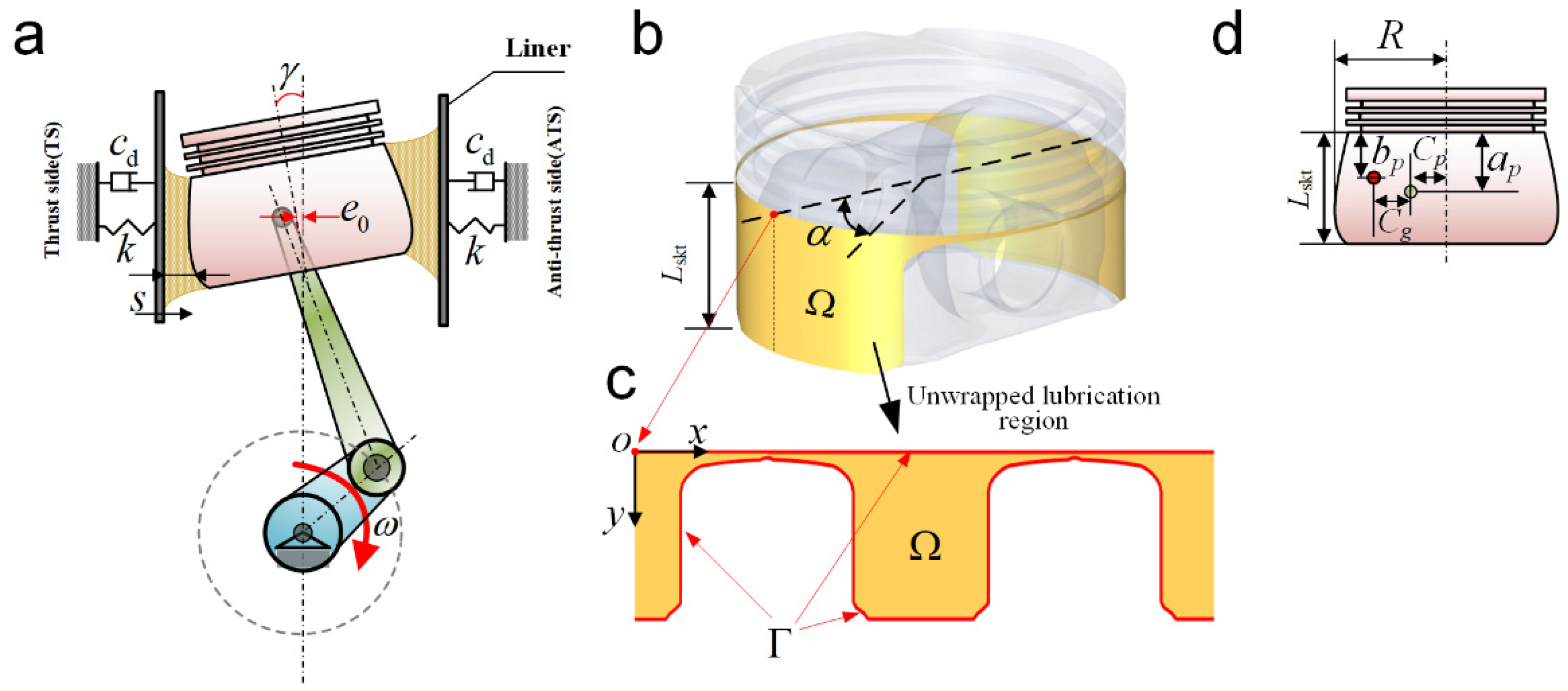
The hydrodynamic lubrication of the skirt–cylinder interface is dependent on the combination of the relative motion of the piston against the cylinder, the micro-vibration of cylinder liner, and the temperature distribution, together with the elastic as well as thermal deformations of the tribo-pair. Furthermore, the combined impact can complicate the piston motion and relate oil film distribution to a lot of elements. As is displayed in Figure 1a, the oil film thickness in the clearance of the skirt–cylinder interface can be expressed as [4,21,30]
where refers to oil film thickness, and indicate separately the local coordinate axes alongside the circumferential and axial directions of the piston skirt, refers to the cold radial clearance, represents the profile of skirt, refers to the piston lateral displacement, and is the angle of inclination. stands for the skirt angular coordinate from the TS (thrust slide) side (Figure 1b). means the vertical distance from the top of the piston skirt to the piston pin (Figure 1d). The transverse cylinder liner displacement resulting from vibration is denoted by , and the cylinder liner vibration is not taken into account when is excluded from Equation (2). The clearance elevation attributable to the elastic and thermal distortions of skirt and cylinder is described with the last 4 items. The superscript indicates the elastic distortion, whereas superscript indicates the thermal distortion. Meanwhile, the subscript indicates the distortion on the piston skirt and the subscript indicates that on the internal surface of cylinder. The solid mechanics field is the contributor to the aforementioned distortions in the present work.
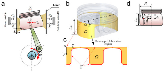
Figure 1.
Schematic of the cylinder–piston–rod–crank system: (a) the oil film thickness of the skirt–cylinder interface, (b) the piston with the lubricated skirt, (c) the unwrapped lubrication region, and (d) the geometry parameters of the piston.
For the hydrodynamics fluid pressure computation in the skirt–cylinder assembly, the average Reynolds equation is employed at the mixed lubrication zone, as [4,7,8]
and
where and refer separately to the fluid density and dynamic viscosity, and the hydrodynamics fluid pressure and speed of the piston are represented by and . The composite roughness is determined according to , with representing the skirt surface roughness and representing the cylinder surface roughness. and refer separately to the pressure-flow variables in the skirt circumferential and axial orientations, whereas and are the contact and shear-flow variables, respectively [36]. In addition, the previous four variables can be considered to be dependent on the surface roughness [7,8].
For the oil film, its squeeze effect is represented by (its derivative about time), and expressed as
where represents the transverse velocity of cylinder liner that takes into account the liner vibration.
For the skirt–cylinder assembly, the expression for lubrication boundary condition is
where represents the lubrication boundary. The schematics of the unwrapped lubrication region are shown in Figure 1c.
Noticeably, the boundary condition adopted herein is unlike those in literature works [21,24,30] that consider the lubrication zone to have a typical rectangular shape. In these works, merely half of the lubrication zone () is taken into account given its symmetrical trait, and on the zonal boundaries and , a supplementary boundary condition (pressure gradient = 0) is imposed [4]. In contrast, the modeling range in the present work is the entire lubrication zone. Despite a higher computational cost, the treatment of boundary conditions is simplified and the lubrication issues are easier to resolve when the boundary shapes are intricate and atypical.
It should be mentioned that this Reynolds boundary neglects oil film reformulation at its boundary. In cases with strong transient effects [37], taking for example the skirt with microscopic shape and texture, the cavitation flow can affect the hydrodynamics pressure significantly, and the cavitation boundary with mass-flux continuity at the film reformation boundary is expected to be adopted to further improve the accuracy of the method.
2.2.2. Rheological Relationship of the Lubricating Oil
The lubricant rheology (density and viscosity) depends on the temperature, pressure, and shear velocity, and these dependents are described with the Vogel model, Roeland model, and Cross equation. The Vogel model is used to characterize the temperature-dependant property of the oil, as following [4,38]
where refers to a constant with the dynamic viscosity unit, and stands for the lubricating oil temperature. Often, the variables and are determined experimentally. Following heat transfer, the instantaneous viscosity is derivable for the lubricating oil based on the steady-state distribution of cylinder temperatures, as well as the instantaneous piston location, according to [39].
The viscosity-dependence of the lubricant on pressure is characterized with the Roeland model [2].
In addition, the lubricant viscosity can also be affected by the shear thinning. The Cross equation can be used to depict the shear rate dependence of the viscosity, as following [40]
where and are the low- and high-shear viscosity of the lubricant, respectively. Parameter is a constant ranging from 0.5 to 1.0 for most multigrade oils. is the critical shear rate of the oil, and expressed as for simplicity. Here, and are lubricant-dependent constants. With the assumption of the Couette flow for the oil film, the shear rate can be expressed as [40]
where is the piston velocity and means the minimum oil film thickness.
Furthermore, the impact of the temperature and pressure on the oil density can also be elaborated with the Dowson–Higginson model, and expressed as [40,41]
where indicates the oil density under the atmospheric pressure and the lubricant temperature refers to , with being the thermal expansion coefficient of the oil. In this study, a commercial lubricating oil SAE20W50 is adopted, and the parameters of its rheological properties can be found in Table 1.

Table 1.
Oil rheological properties of SAE20W50.
2.2.3. Asperity Contact Model
The surfaces of the skirt–cylinder interface are not perfectly smooth, but rough and covered with asperities. The oil film thickness on the interface is of the same order of magnitude as the roughness of the surfaces. When the lubricating oil film between the piston and the cylinder liner is very thin, the two lubricating surfaces will come into asperity contact. It has a certain impact on the lubrication performance of the skirt–cylinder system. Therefore, apart from the hydrodynamic oil film force, the equivalent asperity contact force in mixed lubrication should also be considered.
There are two methods for predicting the contact pressure of asperities, one being the deterministic method in which the actual measured surface profile data is used as input to characterize the rough surface, and the other is the statistical method which uses a series of statistics parameters to characterize rough surfaces [1,21]. Due to the high computational cost of the former method, the latter method is represented by Greenwood–Tripp asperity contact model. This is based on the Gaussian distribution assumption for the surface roughness which is reliable and widely used in engineering, since most engineering surfaces have approximately Gaussian distribution of roughness heights.
In the mixed lubrication region, this study adopts the Greenwood–Tripp model for calculating the asperity contact pressure, as [4,42,43]
and
where indicates the composite elastic modulus of the tribo-pair, and can be computed by Young’s modulus of the piston skirt () and cylinder () as . In this study, it is assumed that is a constant of . is expressed as [4,42,43]
2.3. The Solid Mechanics Physical Field for Elastic and Thermal Deformation
The overall piston distortion, particularly the skirt distortion, is caused by the inertial force and the hydrodynamic fluid pressure jointly with the combustion pressure imposed on the piston top [25]. Consequently, the hydrodynamic fluid pressure distribution at the interface between liner and skirt is impacted and so, accordingly, are the tribological traits. For the derivation of the piston elastic distortion, elicited by oil film pressure and corresponding clarification of its influence on the thickness of oil film ( in Equation (2)), the constitutive model and motion equation of the material are described on the basic of the solid mechanics theory. Given the small deformation during the operation, the material of the skirt–linear assembly can be deemed linearly elastic.
Based on the first Piola–Kirchhoff stress tensor, the motion equation of the material is depicted as [4,44,45]
where the total deformation gradient tensor can be depicted as . In this study, refers to the total inelastic deformation tensor, and originates from thermal expansion as illustrated in Equation (21). suggests the elastic deformation gradient tensor and the displacement gradient. stands for the volume force vector. represents the unit matrix. denotes the stress tensor. On the basis of Hooke’s law, the constitutive model for a linear elastic material is depicted as
and
where indicates the initial stress tensor. refers to an extra stress tensor. means the external stress tensor. is the ratio between current and initial volume (or mass density). refers to the 4th order elasticity tensor, relying on Young’s modulus and Poisson’s ratio of the material.
The elastic Green–Lagrange strain tensor is computed as
In the geometric nonlinearity case, the strains are indicated by the Green–Lagrange strain tensor, as
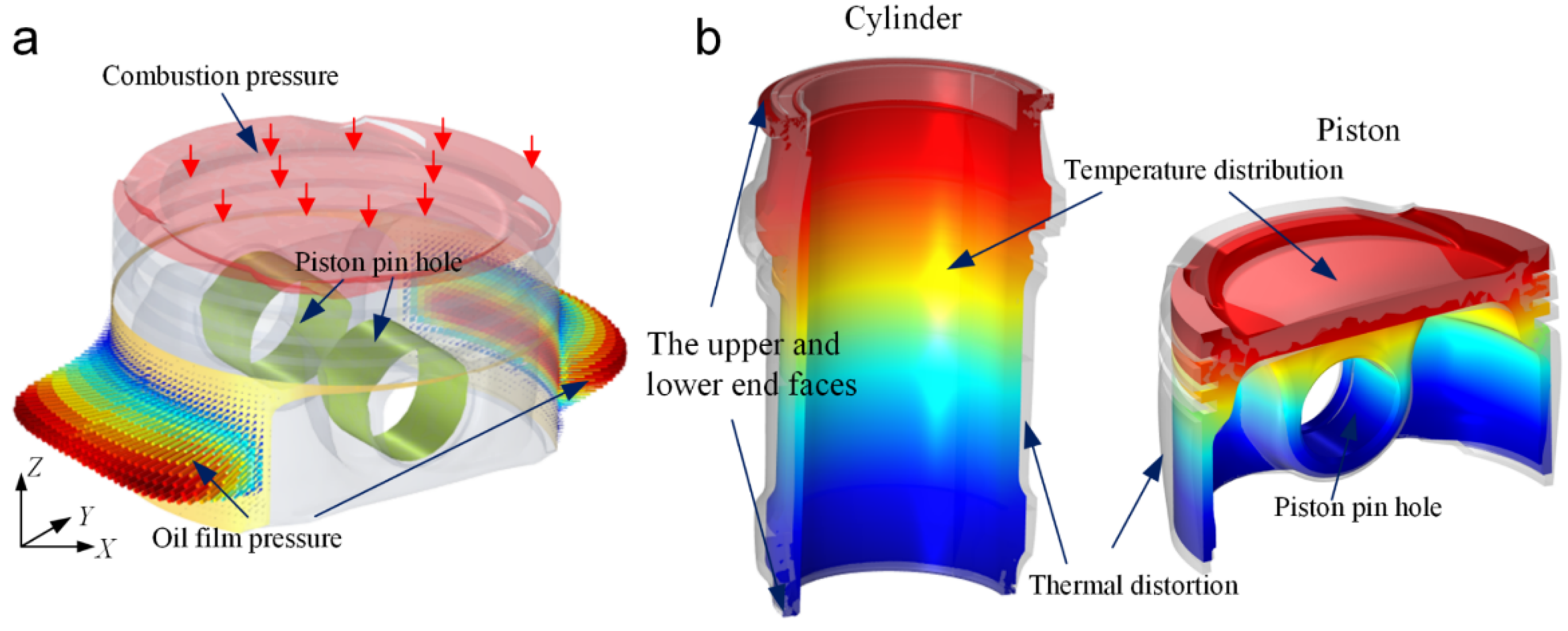
Computation of piston distortion is achievable by utilizing the boundary conditions illustrated in Figure 2a. The external surface of the skirt is imposed on by the oil film pressure derived by average Reynold equation, jointly with the combustion pressure that is imposed on the piston crown in the downright orientation. As displayed in Figure 2a, the rigid motion of the piston pin bore is limited by confining its internal surface, which conforms to the real piston operating condition. It is also worth noting that in the classic EHL studies, the mere elastic distortion of the skirt surface can be considered through Boussinesq’s theory of elasticity [29,30], whose accuracy is high merely when the speed and load are both low. The elastic distortion of skirt in the present work is taken into account through the internal surface confinement for the piston pin bore.
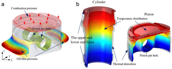
Figure 2.
The schematic of boundary conditions for (a) elastic deformation of the piston, and (b) thermal deformation of cylinder and piston.
After the implementation of the heat transfer, the thermal deformation of the piston–cylinder assembly can be computed with the thermal expansion model [46]
where refers to the thermal strain, represents the thermal expansion coefficient of the material, and remains uniform zero thermal stress reference temperature. In accordance with Equation (15), the thermal expansion of the material can produce extra inelastic deformation tensor to the total deformation gradient tensor, and can be expressed as
where is the total strain. is inelastic deformation strain, is an initial strain, and is an external strain. During assessment of the thermal expansion, the upper- and lower-cylinder end faces have constrained motion (Figure 2b,c). The piston pin bore movement, which is vertical to the piston pin, is restricted, showing conformity to the real piston operating condition as described in [32].
2.4. Multibody Dynamics Physical Field
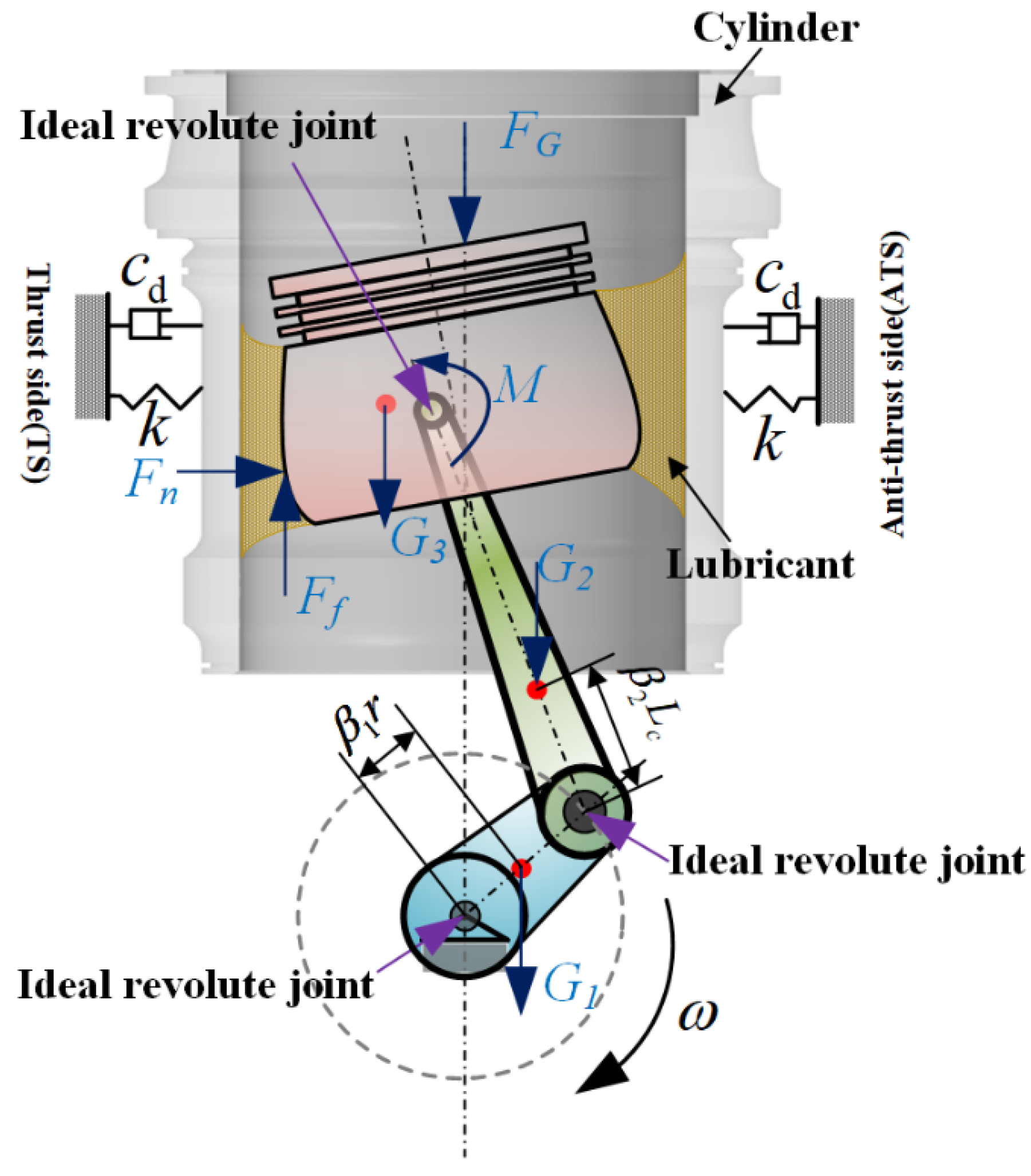
In accordance with Figure 3, by disregarding the component flexibility, the crank–connecting rod–piston–cylinder assembly can be deemed as a system of rigid multibody dynamics. Linkages among these components are achieved via the oil film forces or rotational joints. There is an interaction of the dynamic performance of the assembly with the lubrication of interface between liner and skirt. The dynamic expressions for the coupling of the assembly to the lubricated joint are as presented below [47]:
and
where stands for the mass matrix of entire system encompassing all the components. The crank and rod masses are denoted separately by and , whereas the mass aggregate of piston and pin is denoted by . represents the inertial matrix moment about the barycenter. The inertial moments of crank and rod are denoted by and . stands for the inertial moment of piston plus pin. and refer to the angular and translational accelerations for a rigid domain. stands for the current rotation matrix. refers to the forces with joint restraints as the primary source, whereas denotes the outside forces comprising the gravitational force of every component and the lubrication forces. and separately refer to the inertial and external moments. The centroid position of each component is shown in Figure 3.
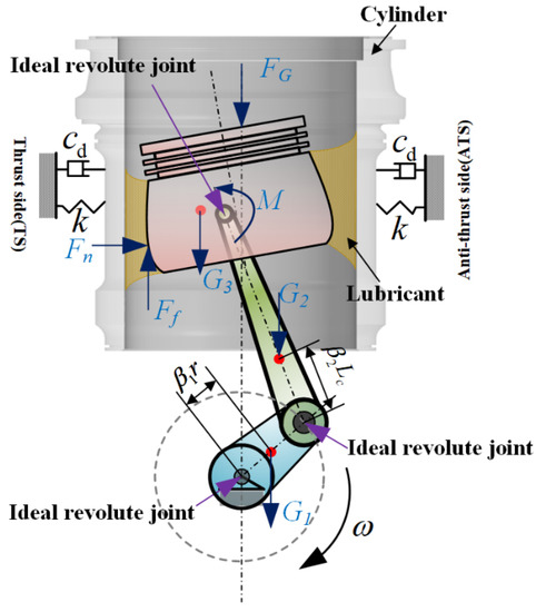
Figure 3.
The external forces and moments of cylinder–piston–rod–crank system.
The lubricated translational joint is adopted herein for the piston skirt–cylinder assembly, whereas the ideal planar joints (absence of friction and clearance) are adopted for other rotational joints (e.g., the principal bearing of crankshaft and the bearings at two connecting rod ends). The rotational speed of the crank is kept fixed at . For the ideal planar revolute joint, the destination attachment (center of the journal) is free in rotating relative to the source attachment (center of the bushing) about the joint axis. This kind of connection applies a kinematic constraint to the system, and can be described as [48]
where and denote the displacement vectors in the global and local coordinate systems, respectively. The subscripts and denote, respectively, the destination and source attachments, and the subscript represents the centroid of attachments. The subscript means the joint center, and is the rotation matrix describing the rotation of attachment. is the unit matrix.
As shown in Figure 3, the assembly gravity, as well as the forces and moments of oil film acquired from the skirt–cylinder interface, can be deemed as the external forces and moments. By integrating the pressure of oil film, the overall normal force , as well as the moment with respect to the axis of piston pin can be achieved, whose expressions are
where stands for the lubrication domain, with details depicted in Figure 1c.
In the mixed lubrication region, the piston is subjected to friction resulting from the lubricant shear and the asperity contact. The expression for the shear stress is [4,7,8]
where , , and are three parameters of shear stress.
The computational expressions for overall frictional force and its moment about the axis of piston pin are
where is the asperity contact coefficient. The above forces and moments are exerted on the mass center of the piston.
There is also vibration of the cylinder liner in the ICE operation process, which is attributed to the piston-triggered slap on the liner, the inertial force of crank–connecting rod–piston, and the combustion gas pressure with varying amplitudes in the cylinder. The vibration model of the cylinder liner and its force analysis are shown in Figure 3. The cylinder liner is deemed as a concentrated mass that moves only laterally [30], the differential equation of cylinder liner vibration established according to Newton’s law is
where and , respectively, refer to the damping and stiffness coefficients for the cylinder liner that is in mass. Meanwhile, , , and represent the liner vibration displacement, speed and acceleration, respectively.
For the piston, in addition to the skirt-induced frictional power loss, the slap-elicited vibration and noise are induced by its secondary motion as well. Therefore, it is necessary to consider both these effects simultaneously for designing an engine with superior efficiency. The piston slap energy on the liner is indicative of the slap noise. The rotational and lateral motion energies constitute the slap energy, whose expression is
where stands for the total mass of piston and pin. indicates the moment of inertia concerning the center of mass (COM) of piston. and are lateral velocity and rotational velocity, respectively. It is of note that this slap energy shows differences from those employed in other studies without the cylinder liner vibration [1,21].
3. Computational Algorithm
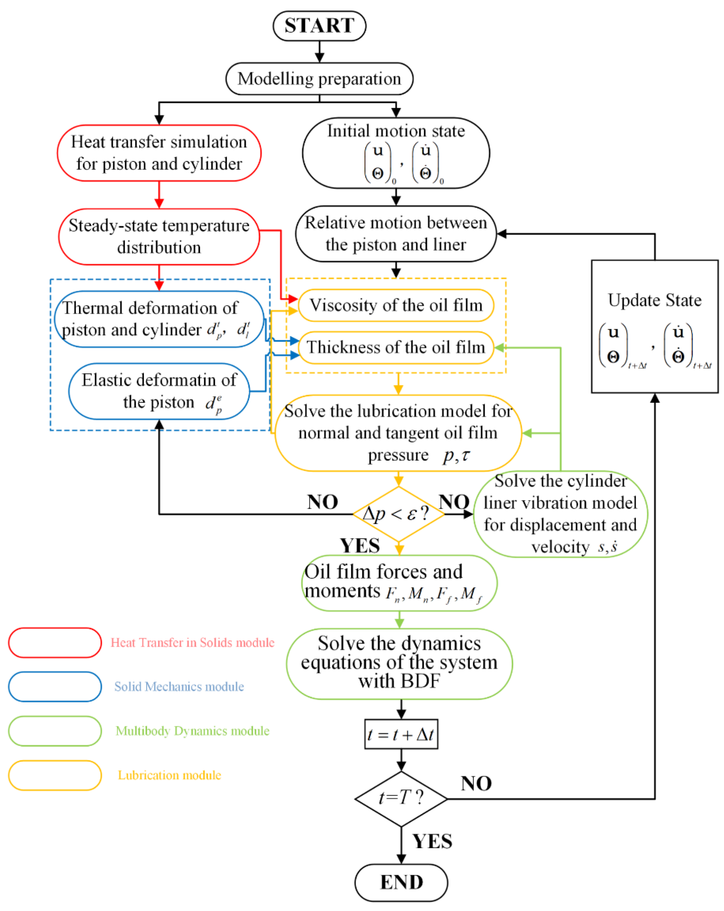
The current work proposes an approach by coupling the above physical fields for forecasting the dynamics and tribological performances of the piston–cylinder system via COMSOL Multiphysics 5.6 software. This method makes full use of the advantages of multiphysical field coupling of the software, as well as the convenience of the partial differential equation (PDE) module to conduct modeling based on equations. With the heat transfer in solids module, the heat transfer simulation for the piston–cylinder system can be performed. Furthermore, the multibody dynamics simulation and the vibration model of the cylinder liner are both conducted under the multibody dynamics module. In addition, the lubrication on the skirt–cylinder interface can be modeled using the average Reynolds equation via the coefficient form of the boundary PDE module. Meanwhile, with the solid mechanics module, the thermal and elastic deformation are calculated. Figure 4 shows the coupling relation of modules, and the computational flowchart are summarized as follows.
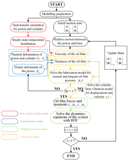
Figure 4.
Computational flowchart of the coupling method.
Step 1: Build the 3D model of the assembly in COMSOL, which includes the cylinder, piston, rod, and crank. Determine the combustion pressure, the rotation speed of the crank, and the temperature boundary of the system, as well as the physical parameters and initial motion state for each component.
Step 2: For deriving the steady-state distribution of temperatures, the steady-state simulation of heat transfer is accomplished on the piston and cylinder with the third kind of thermal boundary conditions. Then, the derived temperature distribution is utilized as the pre-field for the solid mechanics module to facilitate the thermal deformation simulation of the two components.
Step 3: For the oil film, its instantaneous viscosity, thickness, and density at the interface between cylinder and skirt are assessed by exploiting the current movement of piston versus cylinder jointly with the temperature-dependent rheological traits of the lubricant, as well as the thermal distortion. This is followed by the pressure computation of the oil film on the basis of the average Reynolds equation via the PDE module. The elastic distortion computation on the piston skirt is achievable with the solid mechanics module by imposing the oil film pressure and instantaneous combustion pressure on the piston. This process is accompanied by the corresponding thickness updating for the oil film. Under the multibody dynamics module, the vibration displacement of the cylinder liner is computed through exerting instantaneous oil film pressure on the cylinder, and the oil film thickness is updated correspondingly. Based on the existing oil film pressure, the instantaneous viscosity and density for the oil film are determined according to the pressure-dependent rheological performance of lubricant. Afterwards, oil film pressure is calculated in accordance with the updated oil film thickness, viscosity, density, and transverse velocity of the cylinder liner. In addition, the repetition of the process is performed until a steady and convergent oil film pressure can be acquired.
Step 4: According to the acquired convergent oil film pressure, the oil film forces and moments are calculated with Equations (28)–(30), and they are applied on the piston in the integration step. Then the dynamic equations for the system under the multibody dynamics module are solved. At the same time, system motion state is updated in the following integration step through the backward difference formula (BDF). Thereafter, on the basis of the relative movement updates for cylinder and piston, Step 3 is repeated until the wanted simulation duration is attained.
4. Discussion
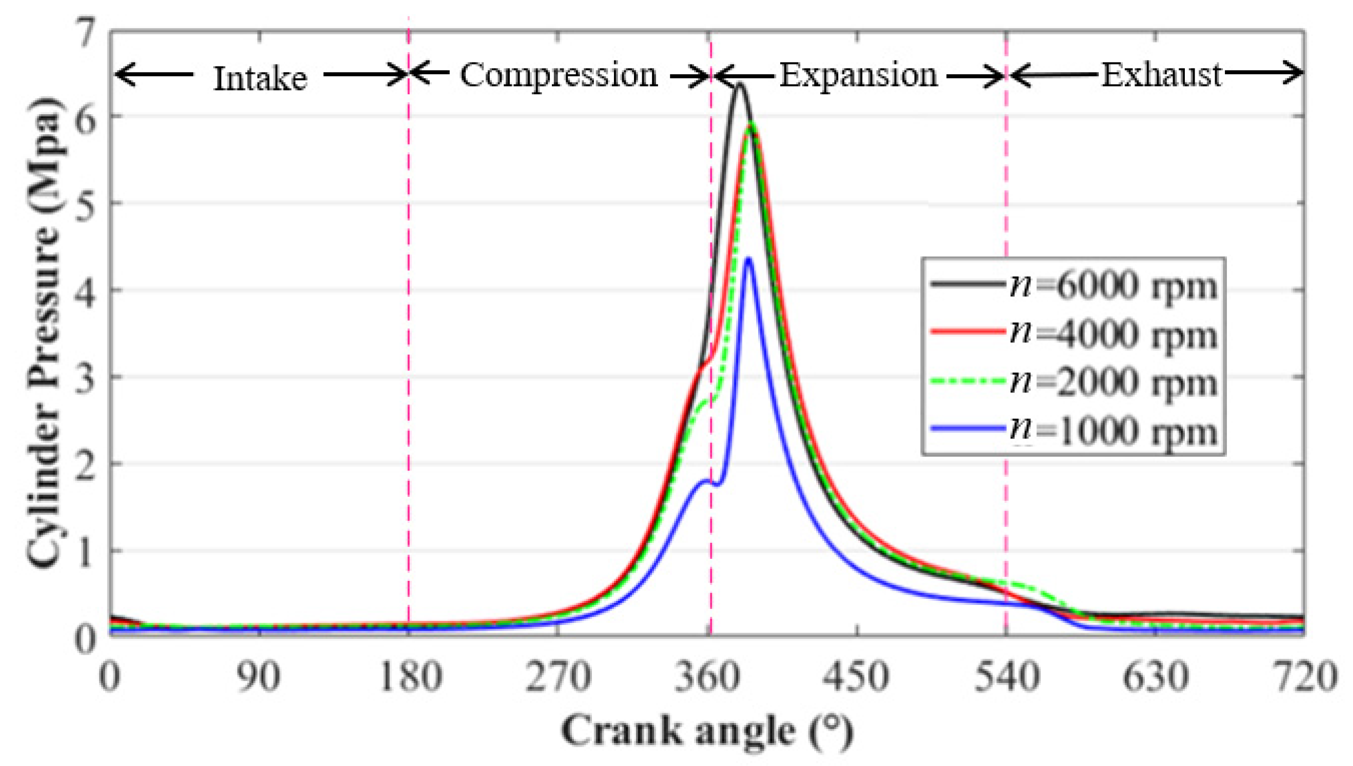
The presented multiphysics coupling approach can be applied in a four-stroke gasoline engine equipped with the lubricated piston skirt–liner subsystem to forecast its dynamic and tribological performances, where the reliability and effectiveness of the approach has been validated, as stated in [4]. Table A1 lists part of the structural and physical parameters, and Table 2 demonstrates the material property parameters for the piston and cylinder in thermal and mechanical analyses. A commercial SAE20W50 lubricating oil [49] is applied as the lubricant, and its rheological characteristics are as seen from Table 1. Figure 5 illustrates the combustion gas pressures for a four-stroke ICE at 1000, 2000, 4000, and 6000 rpm. The combustion gas pressures were obtained from the ignition heat engine test on an internal combustion engine, and the experimental data was offered by our cooperative enterprise [22,24]. Additionally, simulation is accomplished by BDF. The maximum and minimum orders are set separately to 5 and 2, while the maximum step size is equal to 1 × 10⁻⁶. Meanwhile, the convergence criterion can be set to 1 × 10⁻⁵

Table 2.
Material physical parameters of the piston skirt–cylinder system.
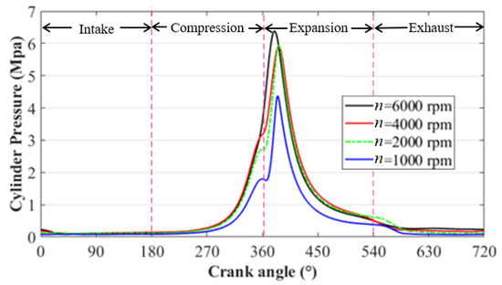
Figure 5.
Combustion pressure at different rotation speeds.
First, the solid heat transfer and thermal deformation are, respectively, performed on the piston–cylinder system. The experimentally computed thermal boundary situations are displayed in Table A1 and Table A2 [4,35]. Figure 6a displays the distribution of temperature on the piston and cylinder at the rotation speeds of 6000 rpm, whereas Figure 6b depicts the thermal deformations on the external surface of the piston skirt and the internal surface of cylinder at the rotation speeds of 6000 rpm. During the later simulations, temperature distribution is the chief influencing factor of lubricant viscosity, while thermal distortion is responsible for the geometry and profile variations of the piston skirt and cylinder.

Figure 6.
Solid heat transfer and heat deformations of the skirt–cylinder system at the rotation speeds of 6000 rpm: (a) temperature field distributions for both piston and cylinder bore, and (b) thermal deformation for both piston and cylinder bore.
4.1. Effects of the Operation Speed on the Tribo-Dynamics Performance of the Piston–Cylinder System
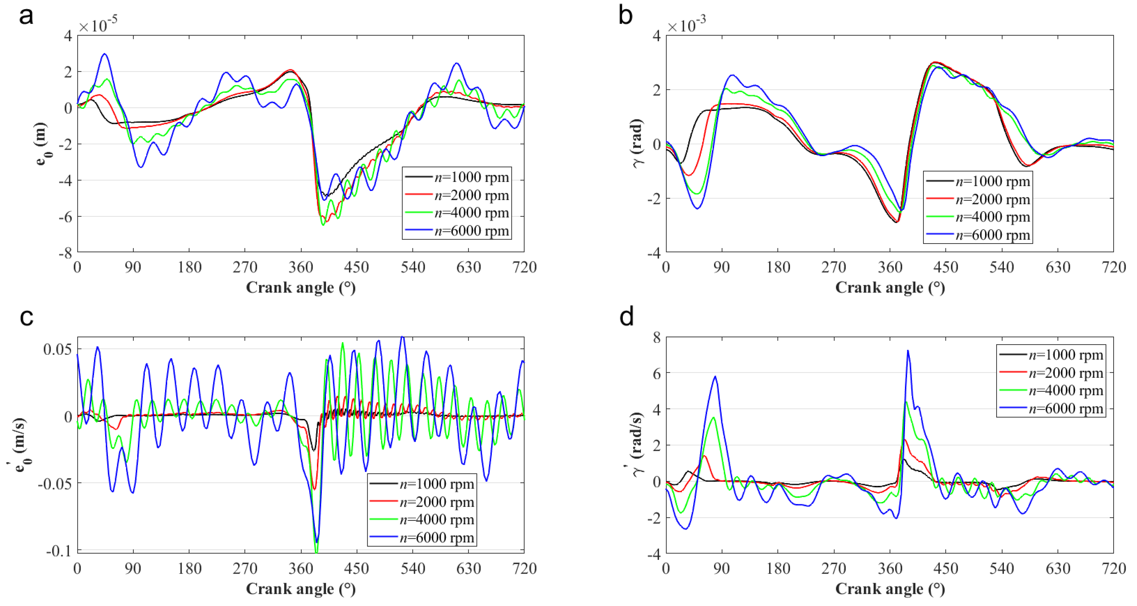
The dependence of the tribo-dynamics performances on the crank rotational speed of the piston skirt–cylinder system is first investigated. As shown in Figure 7, due to the impact load caused by the piston inertia and gas explosion, the cylinder liner presents a severe vibration phenomenon. With the increase of the operation speed, the vibration amplitude (i.e., the lateral displacement and velocity) of the cylinder liner tends to increase and the vibration frequency tends to decrease. Figure 8 demonstrates that the lateral vibration of the piston is similar to that of the cylinder. The reason is that with the increase of rotational speed, the cylinder liner vibration caused by the piston slap is more acute, and the lateral motion of both cylinder and piston are forced to move in the same rhythm due to the contribution of the oil film pressure distributed in the skirt–cylinder interface. This also indicates that in engineering practice, the influence of cylinder liner vibration cannot be ignored, especially when the internal combustion engine is running at a high speed. In addition, it is clear that in the expend stroke and translational and rotational velocities of the piston (i.e., and ) increase with the operation speed of the crank, enhancing the squeeze effect of the lubricating oil and thus reducing the vibration amplitudes of the piston in lateral displacement and velocity (i.e., and ).

Figure 7.
Transient response of cylinder liners with different operation speeds: (a) the lateral displacement, and (b) the lateral velocity.
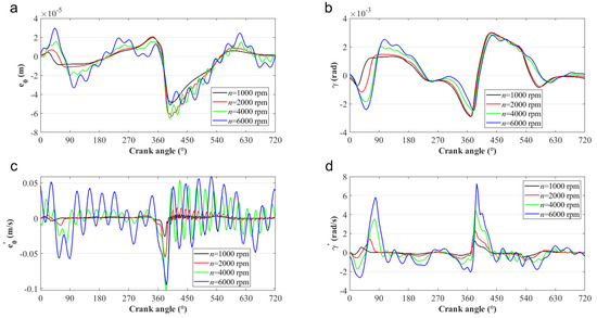
Figure 8.
Dynamic characteristics comparison with different crank rotational speeds: (a) ; (b) ; (c) ; and (d) .
Figure 9a shows the thrust force that acts on the piston skirt under different crank rotational speeds. The thrust forces are primarily exerted for balancing the forces on the piston along the horizontal direction, resulting from the combustion force and the inertia of the piston and connecting rod. In comparison with combustion force-induced forces, the forces arising from the inertia of the piston and connecting rod become dominant and increase as the increase of the crank speed in most cases. Whereas, at around 270–450° CA, the combustion forces reach the maximum, and the thrust forces are primarily adopted for balancing the forces induced by the two forces. Meanwhile, the force directions arising from the inertia of piston and connecting rod are in horizontal opposition to those of the forces arising from combustion forces, which may mitigate the effect of combustion forces. As crank speeds increase, such a weakening effect will be more significant, which causes the reduction of thrust forces, particularly when the speed increases from 2000 to 6000 rpm. This phenomenon has also been found in [23].


Figure 9.
Lubrication characteristics comparison with different crank rotational speeds. (a) thrust force; (b) MOFT; (c) friction force; and (d) friction expansion loss.
As shown in Figure 9b, a higher speed leads to a smaller minimum oil film thickness (MOFT) in most cases. Smaller oil film thickness and larger relative velocity both cause the friction force and friction power loss to increase (Figure 9c,d). Nevertheless, at 270–450° CA, a reserve trend of the MOFT is observed, and asperity contacts take place within a short time. Though direct asperity contacts significantly enhance the friction force, a higher average lubricant shear stress arising from the higher relative velocity, as expressed by Equation (29), remains to be the major friction source. Thus, friction increases with speed. During the period from about 270 to 450° CA, the increased crank speed will not enlarge the thrust force significantly under the combined effect of both combustion force and the inertial force of the crank-rod-piston system, as shown in Figure 9a. However, the increased operation speed can enhance the wedge effect and thus supporting capacity of the oil film. Therefore, the MOFTs in this period increase with the speed. In addition, by comparing the curves in Figure 9a, at different speeds, the effect of cylinder liner vibration on piston side thrust is mainly concentrated in expansion stroke, and the fluctuation tends to increase with speed, which also directly affects the intensity of the local fluctuation phenomenon of MOFT, friction force, and friction expansion loss in the expansion stroke (as shown in Figure 9b–d).
4.2. Effects of the Cylinder Stiffness Coefficient on the Tribo-Dynamics Performance of the Piston–Cylinder System
This subsection investigates the dependence of the tribo-dynamic performance of the piston–cylinder system on the cylinder stiffness coefficient. The operation speed is 4000 rpm, and damping coefficient is 100 Ns/m. Four different stiffness coefficients of the cylinder with values of 6.0 × 10⁴, 8.0 × 10⁴, 1.5 × 10⁵ kN/m, and infinite are chosen. Here can be regarded as the case without considering cylinder liner vibration.
As shown in Figure 10, the peaks of the lateral vibration displacement and velocity of the cylinder liner with different stiffness coefficients appear in the expansion stroke. This is due to the high gas burst pressure during the expansion stroke that causes the piston to slam into the cylinder liner. With the increase of the stiffness coefficient, the vibration frequency of the cylinder liner increases and the vibration amplitude decreases. The lateral vibration displacement in the cylinder can influence the oil film thickness distribution, and the vibration velocity can produce an extra squeeze effect on the film as stated in Equation (5), thus significantly affecting the lubrication performance of the piston skirt–cylinder system.

Figure 10.
The transient response of cylinder liners with different stiffness coefficients: (a) the lateral displacement, and (b) the lateral velocity.
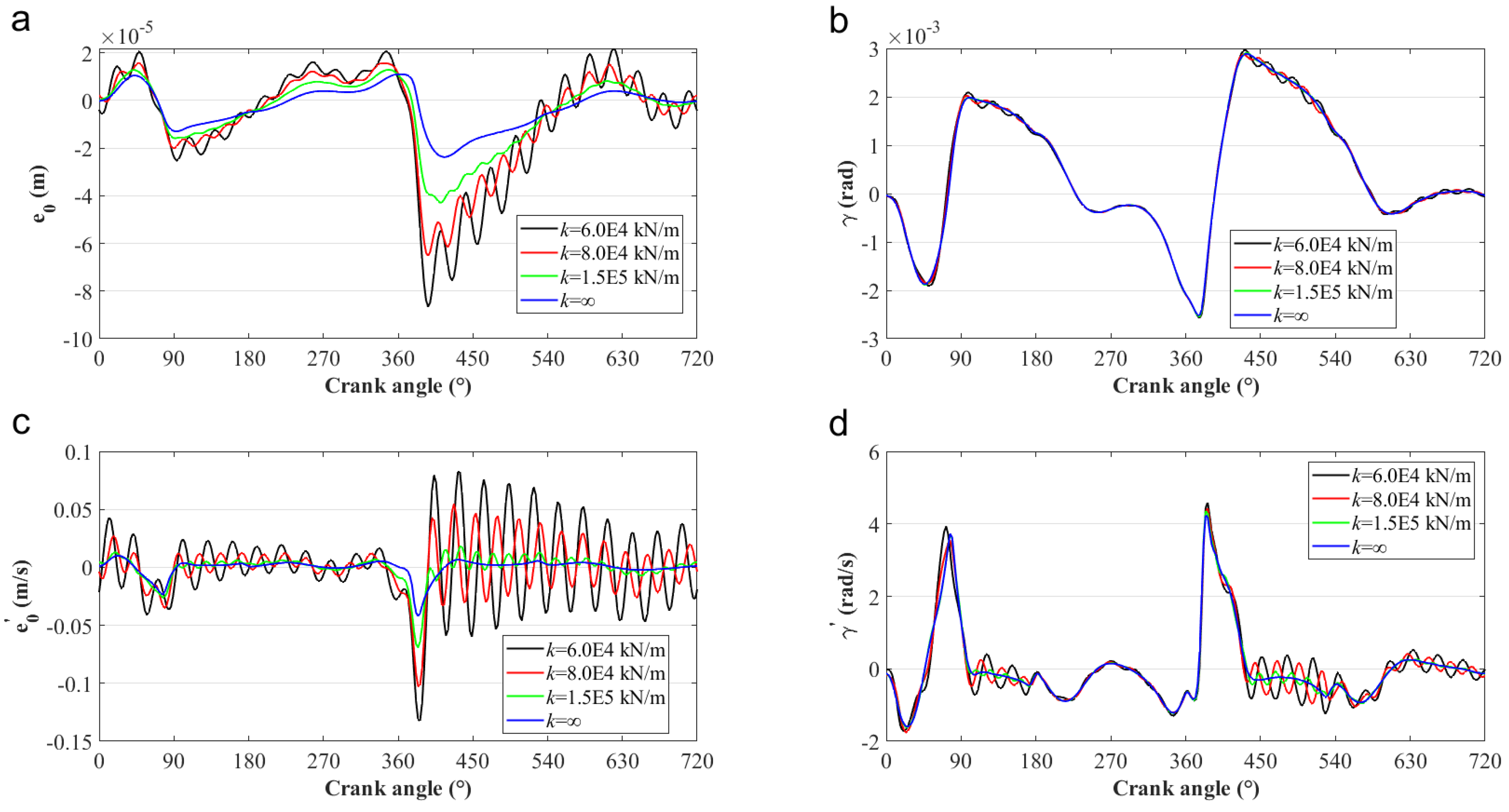
The severe cylinder liner vibration fluctuates the oil film-bearing capacity of the skirt–cylinder interface, and thus impacts on the piston secondary motion. Figure 11 shows the influence of the stiffness coefficient on the piston secondary motion. It is clear that the cylinder vibration has an obvious influence on piston lateral motion ( and ), especially during the expansion stroke, but little influence on the tilt motion ( and ). With the increase of the stiffness coefficient, the amplitudes of the lateral displacement and velocity of the piston tends to decrease, which means that the motion of the piston becomes more stable. In comparison with Figure 10, it is also obvious that the lateral vibration of the piston is similar to that of the cylinder. Thus, cylinder vibration drives the piston to obey its motion through squeezing the oil film distributed in the interface.
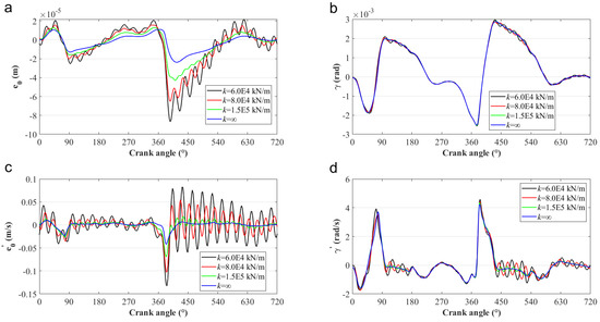
Figure 11.
Comparisons of the piston secondary motion in the system with different stiffness coefficients of the cylinder: (a) ; (b) ; (c) ; and (d) .
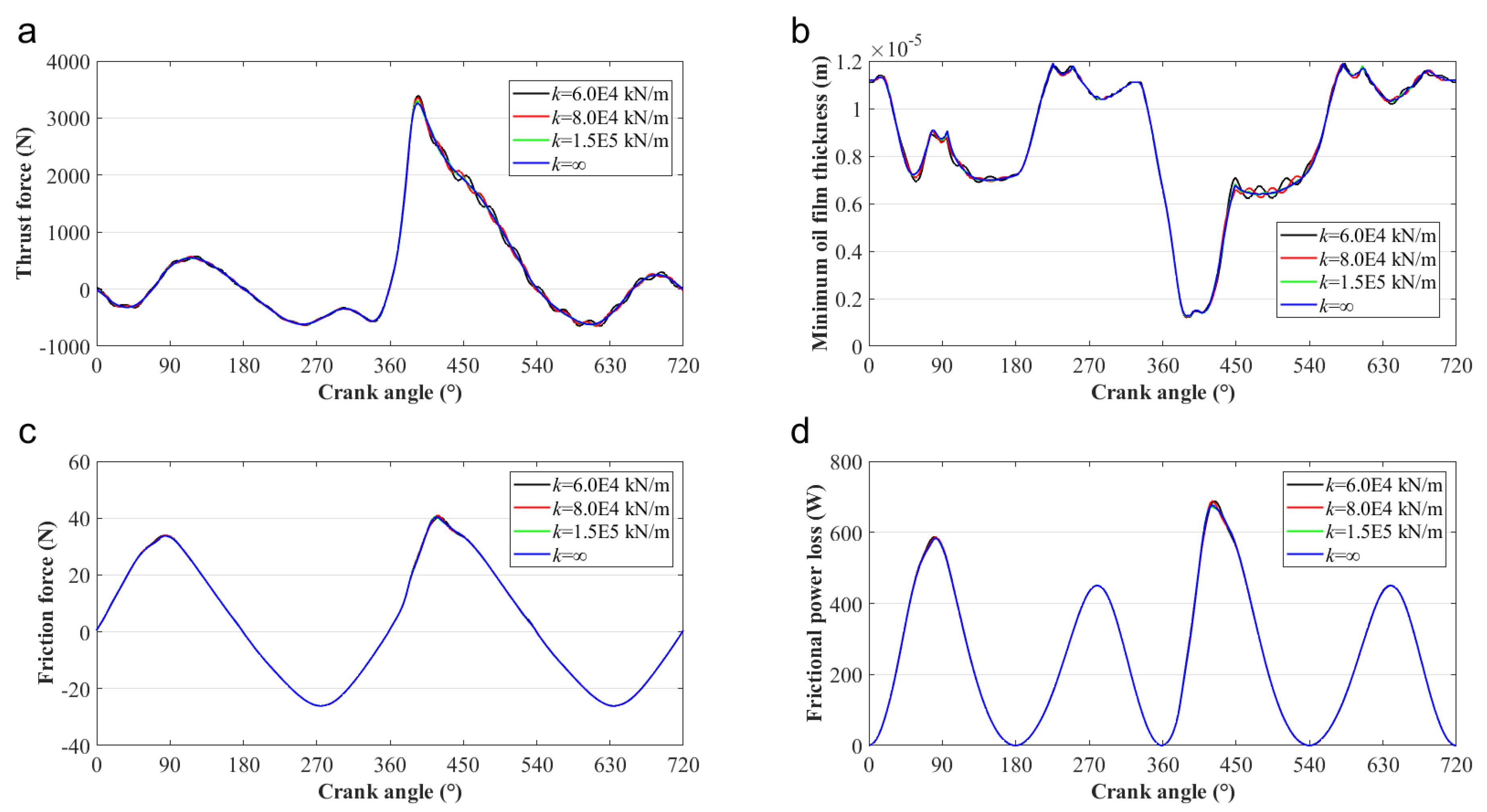
Figure 12 compares the lubrication features of the piston skirt–cylinder system with different cylinder stiffness coefficients. It can be found that the vibration of the cylinder has little effect on system tribological performance. That is because the vibration synchronicity of cylinder and piston (shown in Figure 10 and Figure 11) ensures the distributions of oil film thickness and pressure, almost independent of the vibration of the system.
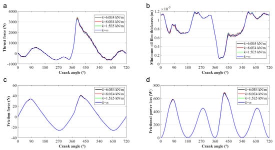
Figure 12.
Comparisons of the lubrication characteristics of the piston–cylinder system with different cylinder stiffness coefficients: (a) thrust force; (b) MOFT; (c) friction force; and (d) friction expansion loss.
4.3. Effects of the Cylinder Damping Coefficient on the Tribo-Dynamics Performance of the Piston–Cylinder System
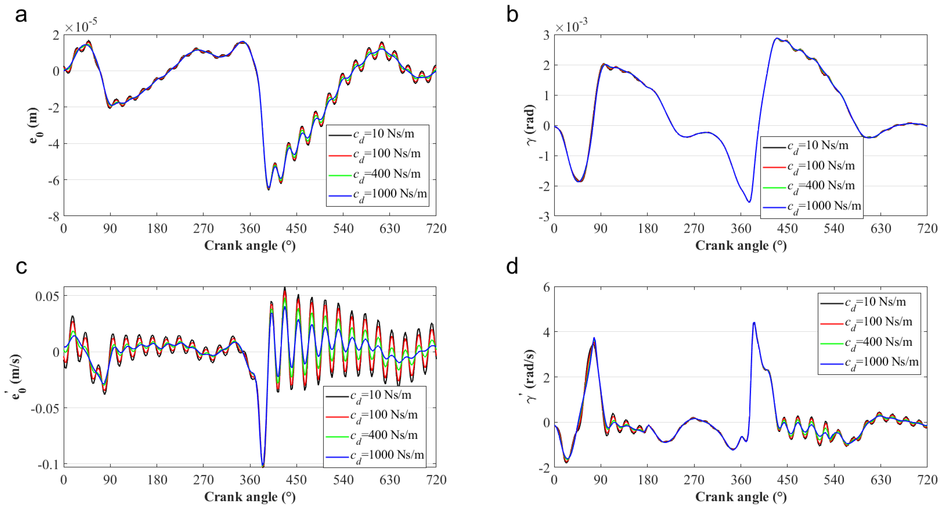
The damping property of the cylinder is determined by the installation condition. The damping of the cylinder can dissipate the vibration energy, and thus affect system tribo-dynamics performance. In this subsection, the operation speed is 4000 rpm, and the cylinder stiffness coefficient is set to 8.0E4 kN/m. Four different damping coefficients with values of 10, 100, 400, and 1000 Ns/m are chosen to uncover their influence on system tribo-dynamics performance.
Figure 13 shows the vibration displacement and velocity of the cylinder with different damping coefficients. It is clear that because of the energy dissipation property of damping, a larger damping coefficient is beneficial to suppress the vibration of the cylinder. However, the damping rarely affects the vibration frequency of the cylinder. This is because the vibration frequency of the system mostly depends on its density distribution, stiffness characteristics, and the external excitation.

Figure 13.
Transient response of cylinder with different damping coefficients: (a) the lateral displacement, and (b) the lateral velocity.
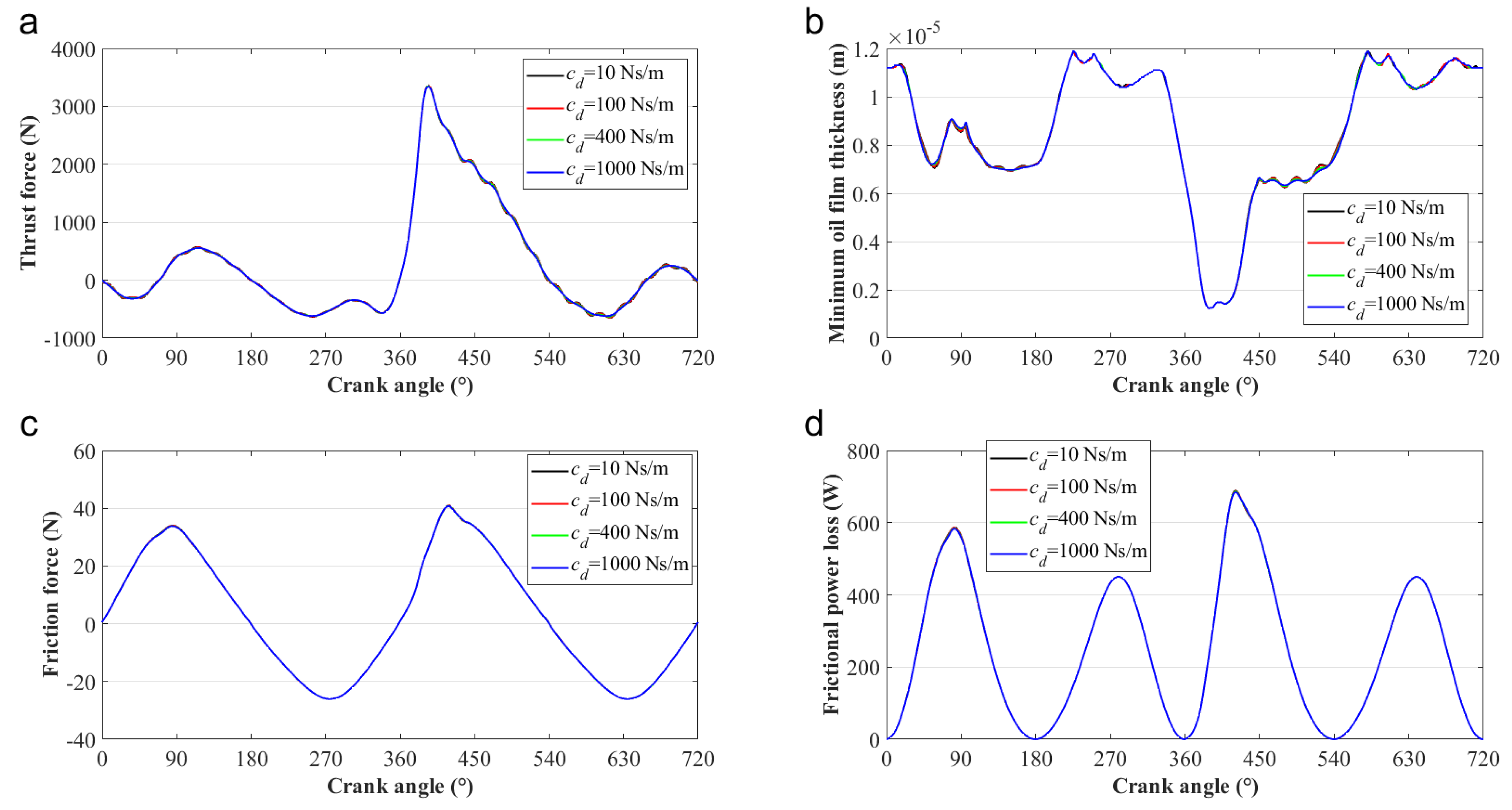
Figure 14 compares the piston secondary motion in the system with different damping coefficients of the cylinder. It is also clear that the piston has a similar vibration to the cylinder, and the large damping coefficient of the cylinder is favorable to the piston motion stability. Therefore, in the actual use of the engine, the piston vibration characteristics can be improved by appropriately increasing the cylinder liner damping, so as to reduce the piston fatigue failure problem and thus enhance the service life of the ICE. Furthermore, Figure 15 shows the vibration improvement on the piston–cylinder system caused by increased cylinder damping rarely affects the lubrication characteristics on the lubricated interface due to the vibration synchronicity of the cylinder and the piston (shown in Figure 13 and Figure 14).
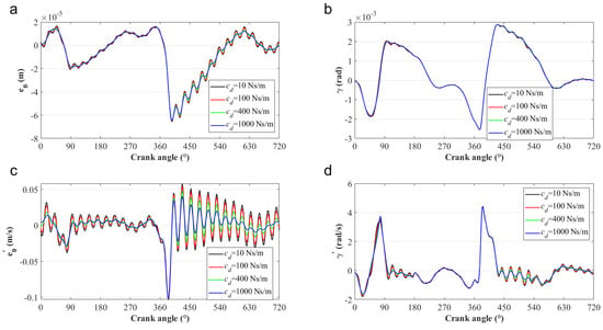
Figure 14.
Comparisons of the piston secondary motion in the system with different damping coefficients of the cylinder: (a) ; (b) ; (c) ; and (d) .
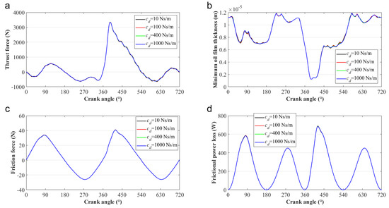
Figure 15.
Lubrication characteristics comparison with different damping coefficients: (a) thrust force, (b) MOFT, (c) friction force, and (d) friction expansion loss.
Furthermore, the simulation results in this study lead to a few major conclusions: (1) the vibration and friction power loss of the piston–cylinder system tend to increase with operation speeds. (2) Increasing the stiffness coefficient of the cylinder is beneficial to suppressing the vibration of the system and enlarging the vibration frequency of the system, but has little effect on the tribological characteristics of the piston skirt–cylinder interface. (3) Increasing the damping coefficient of the cylinder is beneficial to suppressing the vibration of the system, but it has little effect on the vibration frequency of the system or the tribological characteristics of the piston skirt–cylinder interface. The above conclusions are consistent with those found in [29,30], which can also validate the current study to some extent.
5. Conclusions
In the current research, a multiphysics field coupling simulation is conducted considering the vibration of the cylinder as well as including a more complete rheological viscosity model of the lubricant. Simulation results lead to a few major conclusions: (1) the vibration of the piston–cylinder system increases with the operation speed of ICE because of the increased slap energy between the piston and the liner. Moreover, the friction power loss tends to increase with operation speeds due to the enlarged oil film shear stress. (2) The lateral stiffness coefficient of the cylinder has a significant influence on the secondary motion of the piston. Increasing the stiffness coefficient of the cylinder is beneficial to suppress the vibration of the system and enlarge the vibration frequency of the system, but it has little effect on the tribological characteristics of the piston skirt–cylinder interface. (3) Due to the energy dissipation property of damping, increasing the damping coefficient of the cylinder is beneficial to suppress the vibration of the system, but it has little effect on the vibration frequency of the system, as well as the tribological characteristics of the piston skirt–cylinder interface.
Author Contributions
Conceptualization, B.Z. and Y.L.; methodology, S.W.; software, S.W. and X.H.; validation, B.Z., L.X. and Y.L.; formal analysis, X.S.; investigation, P.X. and X.H.; resources, B.Z.; data curation, B.Z.; writing—original draft preparation, S.W. and X.H.; writing—review and editing, B.Z. and S.W.; visualization, S.W. and X.S.; supervision, Y.L.; project administration, P.X.; funding acquisition, L.X. All authors have read and agreed to the published version of the manuscript.
Funding
This research work is supported by the National Natural Science Foundation of China (51909254, U22A2012, 61901273), the Youth Innovation Promotion Association CAS (No. 2021023), Key Program of Marine Economy Development Special Foundation of Department of Natural Resources of Guangdong Province (GDNRC [2022]19).
Data Availability Statement
All data included in this study are available upon request by contact with the corresponding author.
Conflicts of Interest
The authors declare no conflict of interest.
Appendix A
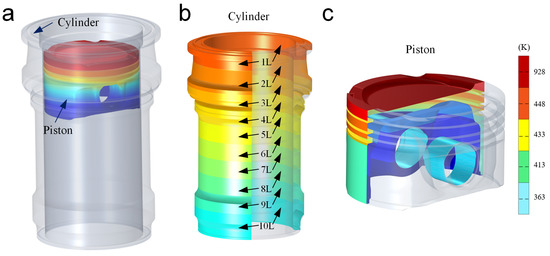
Figure A1.
The schematic thermal boundary conditions of cylinder and piston: (a) the schematic of the piston–cylinder system, (b) the thermal boundary of the cylinder, and (c) the thermal boundary of the piston.
Figure A1.
The schematic thermal boundary conditions of cylinder and piston: (a) the schematic of the piston–cylinder system, (b) the thermal boundary of the cylinder, and (c) the thermal boundary of the piston.
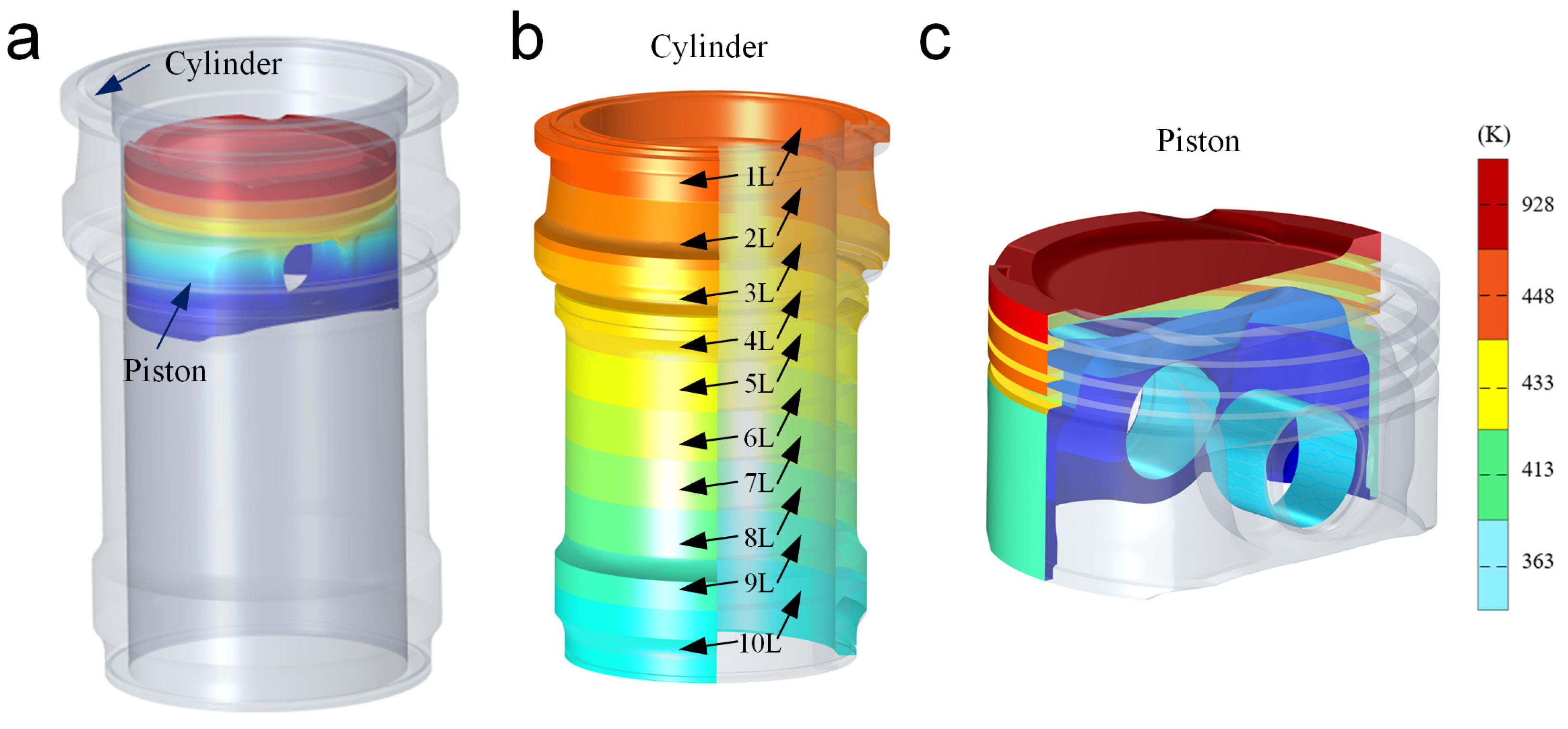

Table A1.
Structural and physical parameters of a four-stroke gasoline engine [4].
Table A1.
Structural and physical parameters of a four-stroke gasoline engine [4].
| Parameters | Values | Parameters | Values | Parameters | Values |
|---|---|---|---|---|---|
| −1.737 mm | 1.29 × 10⁻⁴ kg m2 | 0.19 kg | |||
| 11.8 mm | 129.5 mm | 0.074 kg | |||
| 0.7 mm | 39.93 mm | 2 kg | |||
| 0.13 mm | 28 mm | 0.13 | |||
| 0.015 mm | 36.485 mm | 8 × 10⁻⁴ kN/m | |||
| 0.345 kg | 0.50 | 100 Ns/m | |||
| 9.67 × 10⁻⁴ kg m2 | 0.22 |

Table A2.
Thermal boundary conditions of cylinder [35].
Table A2.
Thermal boundary conditions of cylinder [35].
| Boundary Area | The Third Boundary Condition | ||
|---|---|---|---|
| Ambient Temperature (K) | Heat Convection Coefficient (W/(m2 K)) | ||
| 10 sections from the top to the bottom of the cylinder | 1 (1L) | 2600 | 500 |
| 2 (2L) | 2050 | 390 | |
| 3 (3L) | 1620 | 320 | |
| 4 (4L) | 1360 | 285 | |
| 5 (5L) | 1130 | 265 | |
| 6 (6L) | 970 | 250 | |
| 7 (7L) | 850 | 230 | |
| 8 (8L) | 790 | 200 | |
| 9 (9L) | 650 | 150 | |
| 10 (10L) | 570 | 80 | |
References
- He, Z.; Xie, W.; Zhang, G.; Hong, Z.; Zhang, J. Piston dynamic characteristics analyses based on FEM method Part I: Effected by piston skirt parameters. Adv. Eng. Softw. 2014, 75, 68–85. [Google Scholar] [CrossRef]
- Fang, C.C.; Meng, X.H.; Zhou, W.; Huang, H.C. On the tribo-dynamic interactions between piston skirt-liner system and pin assembly in a gasoline engine. Mech. Mach. Theory 2021, 166, 104497. [Google Scholar] [CrossRef]
- Delprete, C.; Razavykia, A. Piston dynamics, lubrication and tribological performance evaluation: A review. Int. J. Engine Res. 2020, 21, 725–741. [Google Scholar] [CrossRef]
- Zhao, B.; Hu, X.; Li, H.; Si, X.; Dong, Q.; Zhang, Z.; Zhang, B. A new approach for modeling and analysis of the lubricated piston skirt-cylinder system with multi-physics coupling. Tribol. Int. 2022, 167, 107381. [Google Scholar] [CrossRef]
- Yasir, H.; Ali, U.; S.Kamran, A.; Cheol, W.P. Numeric based low viscosity adiabatic thermo-tribological performance analysis of piston-skirt liner system lubrication at high engine speed. Tribol. Int. 2018, 126, 166–176. [Google Scholar]
- Li, D.F.; Ezzat, H.A. An automotive piston lubrication model. ASLE Trans. 1983, 26, 151–160. [Google Scholar] [CrossRef]
- Patir, N.; Cheng, H.S. An Average Flow Model for Determining Effects of Three-Determining Effects of Three-Dimensional Roughness on Partial Hydrodynamic Lubrication. J. Lubr. Technol. 1979, 100, 12–17. [Google Scholar] [CrossRef]
- Patir, N.; Cheng, M.S. Application of average flow model to lubrication between rough sliding surfaces. J. Tribol. 1979, 101, 220–229. [Google Scholar] [CrossRef]
- Zhu, D.; Cheng, H.S.; Arai, T.; Hamai, K. A numerical analysis for piston skirts in mixed lubrication—Part I: Basic modeling. J. Tribol. 1992, 114, 553–562. [Google Scholar] [CrossRef]
- Zhu, D.; Hu, Y.Z.; Cheng, H.S.; Arai, T.; Hamai, K. A numerical analysis for piston skirts in mixed lubrication—Part II: Deformation considerations. J. Tribol. 1993, 115, 125–133. [Google Scholar] [CrossRef]
- Keribar, R.; Dursunkaya, Z. A comprehensive model of piston skirt lubrication. SAE Trans. 1992, 101, 844–852. [Google Scholar]
- Wong, V.W.; Tian, T.; Lang, H.; Ryan, J.P.; Sekiya, Y.; Kobayashi, Y.; Aoyama, S. A numerical model of piston secondary motion and piston slap in partially flooded elastohydrodynamic skirt lubrication. SAE Trans. 1994, 103, 1276–1290. [Google Scholar]
- Liu, K.; Xie, Y.B.; Gui, C.L. A comprehensive study of the friction and dynamic motion of the piston assembly. Proc. Inst. Mech. Eng. Part J J. Eng. Tribol. 1998, 212, 221–226. [Google Scholar] [CrossRef]
- Meng, X.; Xie, Y. A new numerical analysis for piston skirtliner system lubrication considering the effects of connecting rod inertia. Tribol. Int. 2012, 47, 235–243. [Google Scholar] [CrossRef]
- Meng, X.; Ning, L.; Xie, Y.; Wong, V.W. Effects of the connecting-rod-related design parameters on the piston dynamics and the skirt-liner lubrication. Proc. Inst. Mech. Eng. Part D J. Automob. Eng. 2013, 227, 885–898. [Google Scholar] [CrossRef]
- Flores, P.; Ambrósio, J.; Claro, J.P. Dynamic Analysis for Planar Multibody Mechanical Systems with Lubricated Joints. Multibody Syst. Dyn. 2004, 12, 47–74. [Google Scholar] [CrossRef]
- Guo, C.; Song, Q.; Liu, Z.; Chen, L. Hydrodynamic lubrication analysis of two-dimensional section between piston skirt and textured cylinder wall considering slip boundary conditions. Tribol. Int. 2019, 140, 105879. [Google Scholar] [CrossRef]
- Ravn, P.; Shivaswamy, S.; Alshaer, B.J.; Hamid, M.L. Joint clearances with lubricated long bearings in multibody mechanical systems. J. Mech. Des. 2000, 122, 484–488. [Google Scholar] [CrossRef]
- Tian, Q.; Zhang, Y.; Chen, L.; Yang, J. Simulation of planar flexible multibody systems with clearance and lubricated revolute joints. Nonlinear Dyn. 2010, 60, 489–511. [Google Scholar] [CrossRef]
- Tian, Q.; Flores, P.; Lankarani, H.M. A comprehensive survey of the analytical, numerical and experimental methodologies for dynamics of multibody mechanical systems with clearance or imperfect joints. Mech. Mach. Theory 2018, 122, 1–57. [Google Scholar] [CrossRef]
- Zhao, B.; Dai, X.D.; Zhang, Z.N.; Xie, Y.B. A new numerical method for piston dynamics and lubrication analysis. Tribol. Int. 2016, 94, 395–408. [Google Scholar] [CrossRef]
- Zhao, B.; Zhang, Z.N.; Fang, C.C.; Dai, X.D.; Xie, Y.B. Modeling and analysis of planar multibody system with mixed lubricated revolute joint. Tribol. Int. 2016, 98, 229–241. [Google Scholar] [CrossRef]
- Zhao, B.; Shen, F. A numerical coupling model for a multibody system with multiple lubricated clearance joints. In MATEC Web of Conferences; EDP Sciences: Les Ulis, France, 2017; Volume 108, p. 15006. [Google Scholar]
- Zhao, B.; Cui, Y.; Xie, Y.; Zhou, K. Dynamics and lubrication analyses of a planar multibody system with multiple lubricated joints. Proc. Inst. Mech. Eng. Part J J. Eng. Tribol. 2018, 232, 326–346. [Google Scholar] [CrossRef]
- Littlefair, B.; De, L.; Cruz, M.; Mills, R.; Theodossiades, S.; Rahnejat, H.; Dwyer-Joyce, R.; Howell-Smith, S. Lubrication of a flexible piston skirt conjunction subjected to thermo-elastic deformation: A combined numerical and experimental investigation. Proc. Inst. Mech. Eng. Part J J. Eng. Tribol. 2014, 228, 69–81. [Google Scholar] [CrossRef]
- Luigi, B.; Saverio, G.B.; Valerio, M.; Matteo, G.; Gabriele, C. Influence of the thermal deformation on the lubricating performance of the piston-gudgeon pin interface in an internal combustion engine. Tribol. Int. 2022, 174, 107719. [Google Scholar]
- Oh, K.P.; Li, C.H.; Goenka, P.K. Elastohydrodynamic lubrication of piston skirts. J. Tribol. 1987, 109, 356–362. [Google Scholar] [CrossRef]
- Zavos, A.; Nikolakopoulos, P.G. Measurement of friction and noise from piston assembly of a single-cylinder motorbike engine at realistic speeds. Proc. Inst. Mech. Eng. Part D J. Automob. Eng. 2018, 232, 1715–1735. [Google Scholar] [CrossRef]
- Meng, F.; Du, M.; Wang, X.; Chen, Y.; Zhang, Q. Effect of axial piston pin motion on tribo-dynamics of piston skirt-cylinder liner system. Ind. Lubr. Tribol. 2017, 70, 140–154. [Google Scholar] [CrossRef]
- Meng, F.M.; Wang, X.F.; Li, T.T.; Chen, Y.P. Influence of cylinder liner vibration on lateral motion and tribological behaviors for piston in internal combustion engine. Proc. Inst. Mech. Eng. Part J J. Eng. Tribol. 2015, 229, 151–167. [Google Scholar] [CrossRef]
- Tan, Y.C.; Ripin, Z.M. Analysis of piston secondary motion. J. Sound. Vib. 2013, 332, 5162–5176. [Google Scholar] [CrossRef]
- Lu, Y.; Zhang, X.; Xiang, P.; Dong, D. Analysis of thermal temperature fields and thermal stress under steady temperature field of diesel engine piston. Appl. Therm. Eng. 2017, 113, 796–812. [Google Scholar] [CrossRef]
- COMSOL Multiphysics. Heat Transfer Module-User’s Guide; COMSOL: Stockholm, Sweden, 2020. [Google Scholar]
- Fang, C.; Meng, X.; Kong, X.; Zhao, B.; Huang, H. Transient tribo-dynamics analysis and friction loss evaluation of piston during cold- and warm-start of a SI engine. Int. J. Mech Sci. 2017, 133, 767–787. [Google Scholar] [CrossRef]
- Ning, L.; Meng, X.; Xie, Y. Incorporation of deformation in a lubrication analysis for automotive piston skirt-liner system. Proc. Inst. Mech. Eng. Part J J. Eng. Tribol. 2013, 227, 654–670. [Google Scholar] [CrossRef]
- Wu, L.; Zheng, C. An Average Reynolds Equation for Partial Film Lubrication with a Contact Factor. Trans. ASME J. Tribol. 1989, 111, 188–191. [Google Scholar] [CrossRef]
- Zhao, B.; Zhang, B.; Zhang, K. Modelling three-dimensional soft elastohydrodynamic lubrication contact of heterogeneous materials. Tribol. Int. 2019, 129, 377–389. [Google Scholar] [CrossRef]
- Hamrock, B.J.; Schmid, S.R.; Jacobson, B.O. Fundamentals of Fluid Film Lubrication; CRC Press: Boca Raton, FL, USA, 2004. [Google Scholar]
- Ma, M.T. Incorporation of lubricant shear-thinning in a two-dimensional lubrication analysis for automotive piston-ring packs. In Proceedings of the CEC/SAE Spring Fuels & Lubricants Meeting & Exposition, Paris, France, 19–22 June 2000. SAE Technical Paper 2000-01-1786. [Google Scholar]
- Gu, C.; Meng, X.; Xie, Y.; Zhang, D. Mixed lubrication problems in the presence of textures: An efficient solution to the cavitation problem with consideration of roughness effects. Tribol. Int. 2016, 103, 516–528. [Google Scholar] [CrossRef]
- Ning, L.; Meng, X.; Xie, Y. Effects of lubricant shear thinning on the mixed lubrication of piston skirt-liner system. Proc. Inst. Mech. Eng. Part C J. Mech. Eng. Sci. 2013, 227, 1585–1598. [Google Scholar] [CrossRef]
- Greenwood, J.; Tripp, J. The contact of two nominally flat rough surfaces. Exp. Mycol. 1981, 5, 323–329. [Google Scholar] [CrossRef]
- Akalin, O.; Newaz, G.M. Piston ring-cylinder bore friction modeling in mixed lubrication regime: Part I—Analytical results. J. Tribol. 2001, 123, 211–218. [Google Scholar] [CrossRef]
- Rokad, V.; Pandya, D.H. Development of 3D improved acoustic transient model for vibro cleaner using COMSOL multiphysics. Mater. Today Proc. 2021, 44, 776–781. [Google Scholar] [CrossRef]
- COMSOL Multiphysics. Structural Mechanics Module-User’s Guide; COMSOL: Stockholm, Sweden, 2020. [Google Scholar]
- Antony, S.A.; Golbang, A.; Harkin, J.E.; Archer, E.; McIlhagger, A. Prediction of part distortion in Fused Deposition Modelling (FDM) of semi-crystalline polymers via COMSOL: Effect of printing conditions. CIRP J. Manuf. Sci. Technol. 2021, 33, 443–453. [Google Scholar] [CrossRef]
- COMSOL Multiphysics. Multibody Dynamics Module-User’s Guide; COMSOL: Stockholm, Sweden, 2020. [Google Scholar]
- Singh, N.K.; Badodkar, D.N. Modeling and analysis of hydraulic dashpot for impact free operation in a shut-off rod drive mechanism. Eng. Sci. Technol. Int. J. 2016, 19, 1514–1525. [Google Scholar] [CrossRef][Green Version]
- Taylor, R.I. Engine friction: The influence of lubricant rheology. Proc. Inst. Mech. Eng. Part J J. Eng. Tribol. 1997, 211, 235–246. [Google Scholar] [CrossRef]
Publisher’s Note: MDPI stays neutral with regard to jurisdictional claims in published maps and institutional affiliations. |
© 2022 by the authors. Licensee MDPI, Basel, Switzerland. This article is an open access article distributed under the terms and conditions of the Creative Commons Attribution (CC BY) license (https://creativecommons.org/licenses/by/4.0/).

