Article

Failure Analysis of Bank-Wall Side Boiler Tube in a Petrochemical Plant

1
Materials Science and Engineering Research Group, Faculty of Mechanical and Aerospace Engineering, Institut Teknologi Bandung, Bandung 40132, Indonesia
2
Reliability and Asset Integrity Division, PT. Chandra Asri Petrochemical (Tbk), Cilegon 42447, Indonesia
3
Research Center for Nanoscience and Nanotechnology, Institut Teknologi Bandung, Bandung 40132, Indonesia
*
Author to whom correspondence should be addressed.
Metals 2022, 12(12), 2064; https://doi.org/10.3390/met12122064
Submission received: 25 October 2022 / Revised: 21 November 2022 / Accepted: 28 November 2022 / Published: 30 November 2022
(This article belongs to the Special Issue Multi-Axial Fatigue and Fracture Behavior in Metals)

Abstract

:
Failure analysis of the petrochemical plant’s bank-wall side boiler tube has been conducted to determine the root cause of tube failure. The tube material is low carbon steel ASTM A178 grade A. Visual examinations of the cracked surface revealed that the fractured surface is flat, without plastic deformation, and several longitudinal and transverse fissures are present. The SEM and optical microscope examinations show that the cracks were intergranular and transgranular. A hydrogen attack caused the intergranular crack, and thermal fatigue produced the transgranular crack. Boiler tube failure was caused by a steam blanket on the sloping tube’s top inner diameter that induced iron oxide deposition and accumulation. Hydrogen was produced after a chemical reaction at the deposit-metal interface between the iron oxide deposit and ingress steam. Local temperature variation on the top part of the sloped tube occurred during the splashing and evaporation of water, promoting thermal fatigue.

1. Introduction

Boilers are the core equipment in petrochemical plants to produce steam for various chemical processes and the steam turbine engine [1]. Generally, the boiler system comprises two drums: water drums and steam drums, which relate to bank-wall side boiler tubes (Figure 1a) [2]. The water stored in water drums is circulated and heated through the boiler tubes by radiation and convection heat transfer to produce steam, which is stored in the steam drums [3,4].
The bank-wall side boiler tube plays a vital role in this steam transfer process. It is exposed to high outside temperatures and steam (including contaminants) on the inside, which is an extreme condition for most metals [5]. The boiler tube may experience failure due to the operating condition, which results in enormous consequences [6,7]. There are several failure modes of boiler tubes that have been identified, such as caustic corrosion [5], stress corrosion cracking [8], oxidation of the fireside wall [9,10], under deposit corrosion, and hydrogen attack [11,12], grain boundary embrittlement by copper [13], and galvanic corrosion [14]. The failure will halt the production process and cause an estimated $5 billion loss in a year [15]. Considering its tremendous loss, the boiler tube’s failure should be reduced by recognizing the possible failure root cause, especially lesson-learned from industrial practices.
This work presents a failure case study of the bank-wall side boiler tube, which is in tube number 7 (Figure 1b). The tube was part of the petrochemical plant’s boiler and failed in January 2019 after 23 years of service, which is generally designed for 25 years. Several laboratory examinations were performed to find the root cause of tube leaks, such as chemical analysis, tensile test, fractography analysis, microstructure analysis, crack initiation and propagation analysis, and deposit identification. The investigation results will be beneficial for petrochemical plants and researchers to avoid similar failures in the future.

2. Materials and Methods

The leaked boiler tube was in tube number 7, as indicated in Figure 1. The leaked part is defined as the cracked part, and the un-leaked part at the bottom is defined as the un-cracked part. The operating conditions of the bank-wall side boiler tube and the tube specification are shown in Table 1.
According to the technical specifications, the boiler tube was made from carbon-manganese steel ASTM A178 Grade A (Table 1). Thus, the boiler tube’s material was verified on its uncracked part by evaluating its chemical composition, microstructure, and tensile properties. The examination results from these tests will be compared to the ASTM A178 Grade A specification to determine the type of boiler tube material [16].
The chemical composition was examined by optical emission spectroscope (OES; ARL 3460, ThermoFisher Scientific, Massachusetts, United States of America). The microstructure examinations were conducted using an inverted metallurgical microscope (Eclipse MA200, Nikon, Yokohama, Japan).
Tensile test specimens were taken from the boiler tube’s uncracked part, followed by machining to produce a mini tensile specimen. The tensile specimen size and testing procedure were based on the ASTM E8 standard [17]. The tensile test was performed using a universal testing machine (UTM; Tarno Grocki UPGH 20, Hottinger Balwin Messtechnik, Darmstadt, Germany) with a constant strain rate of 5 mm/min and a maximum load of 40 kN at room temperature (25 °C).
The specimens for metallography examinations were taken from the cracked and uncracked parts of the tube. Specimens were cut by a diamond disc cutter (Accutom-5, Struers, Düsseldorf, Germany), then mounted in polyester resin, followed by grinding in wet silicon carbide emery papers. After grinding, the specimen was polished in diamond paste solution and etched in 2% Nital solution (2% HNO3 + ethanol) [18].
One way to identify the failure root cause is to observe the fractured surface’s crack pattern and propagation mode. Before fractography analysis, the sample was cleaned by immersing it into an Alconox solution (Alconox Inc., New York, United States of America) consisting of 15-g Alconox and 350 mL demineralized water (Brataco Chemica, Bekasi, Indonesia). The solution was homogeneously mixed for 15 min. The cleaning was conducted in an ultrasonic bath (ASU-2M, AS ONE, Osaka, Japan) at 90 °C for 30 min and repeated until the surface’s cracks were visible. Cleaning agent residues on the surface were removed by immersion in water at 100 °C for 30 min, followed by rinsing in flowing tap water [19]. Then, the fractography examinations were conducted using a stereomicroscope (SMZ18, Nikon, Yokohama, Japan) and a scanning electron microscope (SEM; JSM-6510LA, JEOL, Tokyo, Japan). Detailed observation of the crack propagation mode was conducted by observation of the microstructures on the crack surface.
The boiler tube has been in service for about 23 years; the surface deposit might also help identify the corrosion-related failure root cause by examining the deposit composition and compound type. The deposit’s chemical composition was examined by an energy dispersive spectrometer (EDS; JSM-6510LA, JEOL, Tokyo, Japan). Before the examination, the surface deposit was coated by gold sputter using a fine coater (JFC 1600, JEOL, Tokyo, Japan). Further examination to identify the deposit compound type was conducted by x-ray diffraction (PW3040/x0 X’Pert PRO, PANalytical, Almelo, Netherlands) using a copper tube target.

3. Results

3.1. Site Inspection of Boiler Tube

The leak’s location was inspected by hydrostatic and dye penetrant tests. The revelation of the tube leak location by a hydrostatic test is shown in Figure 2a. Further examination by a dye penetrant test was conducted to find surface cracking on the neighboring tubes (Figure 2b,c). The inspection results show that the leak only occurred in one tube (red arrow in Figure 2a,c), with no surface cracks on the other neighboring tubes (Figure 2b). The leak occurred on the top side of the tube, which is partially embedded in the furnace wall’s castable heat insulation.

3.2. Boiler Tube Materials Verification

Table 2 shows the chemical composition of boiler tube material and the standard composition for ASTM A178 Grade A. Boiler tube material composition is within the ASTM A178 specification range. The tensile properties data of the boiler tube material in Table 3 conform to the ASTM A178 Gr A specification. The micrographs of the bottom tube part (uncracked part) at the longitudinal section’s mid-thickness are shown in Figure 3 at low and high magnifications. The material consists of ferrite and pearlite phases, typical microstructures for hypo-eutectoid carbon steels. The material did not contain any non-metallics and oxides inclusions, and the equiaxed grain shapes indicated that the material had been heat-treated and slowly cool (normalizing or annealing) [20]. Chemical composition, tensile properties, and microstructure conform to ASTM A178 Grade A [16]; thus, the tube material agrees with boiler technical specifications.

3.3. Visual Examination

The leak boiler tube was removed from its location by a disc cutter, where the top part had to be sliced into two pieces because of space limitations during onsite cutting. Figure 4 shows the inner bottom side and two parts of the inner top side. The inner bottom of the tube had a thin reddish surface deposit, and there was no sign of corrosion attack or surface cracks (Figure 4a). The inner top of the tube shows some longitudinal cracks (Figure 4b) and a trace of wall thinning and deposit accumulation (above the yellow line in Figure 4c). Therefore, the top part of the tube had two failure modes: Longitudinal crack and corrosion; there is no significant wall thinning and bulging. Detailed examination of the defective surface will be conducted by stereomicroscope, SEM, and optical microscope.

3.4. Fractography Analysis

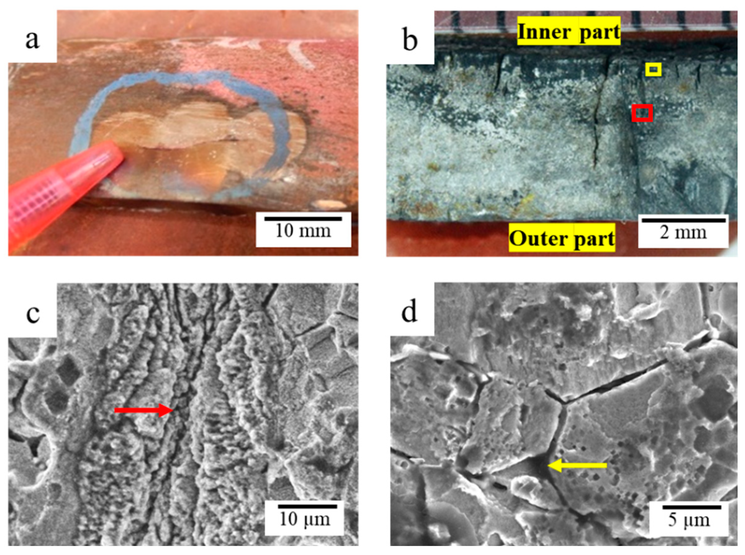
Fractography analysis will be performed to obtain data about crack initiation and propagation, and failure modes. The inner diameter with light corrosion and the leak site’s cracking surface were observed. Microstructure analysis will be performed on one of the leak-fractured surfaces to obtain a detailed crack propagation mode. Figure 5a shows the location of observation in the corroded part. The presence of longitudinal and transverse blistering cracks (fissuring) on the surface can be seen clearly in the stereograph (Figure 5b) and SEM micrograph (Figure 5c), respectively.
At the leaking area of the failed tube, the longitudinal crack was through-thickness, so the crack was observed not only in the inner part but also in the outer part of the tube (Figure 6a). Fractography analysis was conducted by splitting the longitudinal crack at the leaking area (Figure 6a) into two parts. Cross section stereographs image of one of the fractured surfaces is shown in Figure 6b. A sticky deposit that covered the original fractured surface was partially removed by cleaning. However, the black and thicker deposits underneath the inner tube’s surface could not be removed and remained in the specimen (Figure 6b). The fracture appearance shows a brittle-like surface with some transverse fissuring cracks, which had been propagated outward to about 75% of the thickness (Figure 6b).
SEM examinations were conducted to observe the fractured surface in more detail and determine the micro-crack propagation mode. SEM image at the red rectangle area in Figure 6b revealed that many transgranular cracks were observed in the fractured surface (red arrow; Figure 6c). While SEM image at the yellow rectangle area in Figure 6b showed that many intergranular cracks (cracks propagated through grain boundaries) and corrosion attack trace produces micro-crack along grain boundaries were observed in the fractured surface (yellow arrow; Figure 6d). Based on the fracture appearance (brittle-like fracture) and crack morphology (intergranular and transgranular), there are four possibilities of crack origin: creep, hydrogen attack, thermal fatigue, or copper diffusion to grain boundaries. These possibilities will be studied further by microstructure and EDS analysis.

3.5. Microstructure Analysis

The microstructure analysis of the surface crack and the leak site was performed to study the crack propagation mode, possibilities of creep voids, and spheroidized carbides. This examination can support previous fractography analysis results and verify the contribution of creep and hydrogen attack in tube failure.

3.5.1. Microstructure Analysis of Corroded Surface

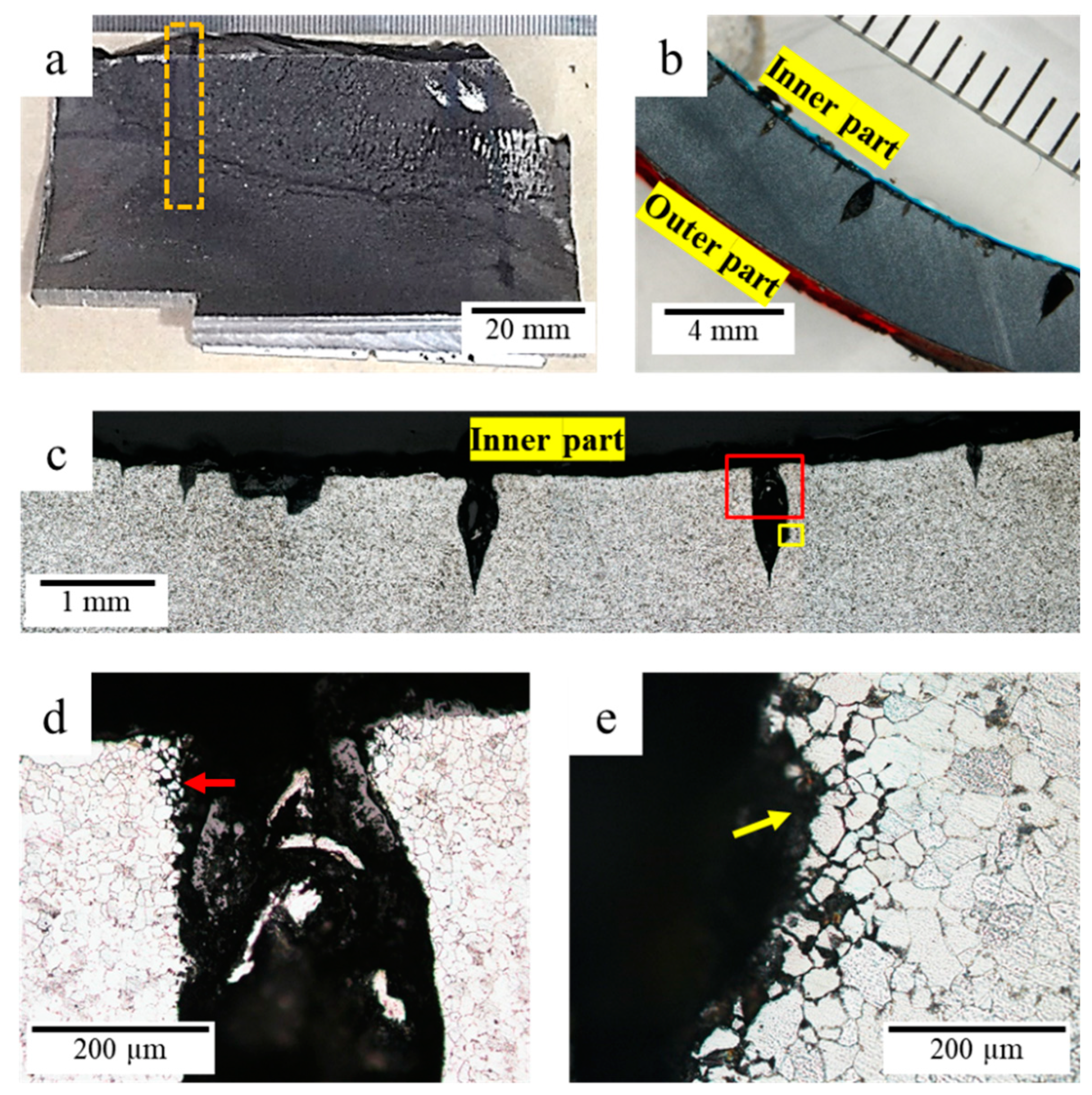
The stereograph (Figure 7b) and optical micrograph (Figure 7c) of a cross-section taken from the sampling location (orange rectangle in Figure 7a) showed that several sharp and blunt microcracks were present in the leak site. The sharp cracks were typical cracks due to thermal fatigue, where the crack interface was oxidized due to high-temperature exposure, and the oxidation products filled the crack [21,22]. Thermal fatigue failure occurs because of temperature fluctuation, creating thermal stress for crack initiation and propagation [23]. Further investigation on the origin of crack initiation was determined by observing the microstructure in one of the selected cracks (Figure 7c). Observation at higher magnification revealed that the intergranular cracking and grain separation caused the crack initiation, as shown at the initial crack of the initiation site (red arrow, Figure 7d) and near the crack tip (yellow arrow; Figure 7e), respectively.
The result confirmed that creep was not the root cause of crack initiation because creep voids and spheroidized carbides in the crack interface’s vicinity were not present [24]; therefore, two other remaining root causes shall be considered. The other possible root causes are hydrogen attack and copper diffusion to grain boundaries. The hydrogen attack might initiate cracking, as shown in Figure 7e, by the presence of the decarburized layer and intergranular crack (yellow arrow in Figure 7e) around the crack interface [25].

3.5.2. Microstructure Analysis of Leak Interface

The cross-section micrographs at the leak site’s crack interface were examined to observe the root cause of crack initiation and the propagation mode. Figure 8a shows the stereomicrograph of one of the crack surfaces where several thermal fatigue cracks with different lengths were present and started from the inner tube diameter. These findings indicated that multiple crack initiation occurred on the inner diameter before the leak. The micrographs of the crack surface at low and high magnifications are shown in Figure 8b,c, respectively. The pearlite phase around the crack interface was decomposed; however, spheroidization of cementite did not occur yet, because no spheroidized carbides were observed. It can also be seen in Figure 8b,c that the crack was initiated by intergranular cracking on the inner diameter of the tube. The crack was stopped temporarily and followed by transgranular cracking.
It can be concluded that the crack initiation was due to a corrosion attack and was followed by thermal fatigue. The corrosion attack and thermal fatigue produced intergranular and transgranular fractures, respectively. The origin of corrosion attack and thermal fatigue will be explored by studying the origin of deposit formation and thermal cycle during deposit accumulation.

3.6. Analysis of Deposit

The deposit analysis was conducted on the tube’s five locations: the inner bottom surface, the inner top surface at the corroded area, the short crack’s inner side, the long crack’s inner side, and the grain boundary. The deposit at the inner side of the crack area was examined to assess the trace of copper penetration from the surface that might contribute to crack initiation by galvanic corrosion or embrittlement of the grain boundary.
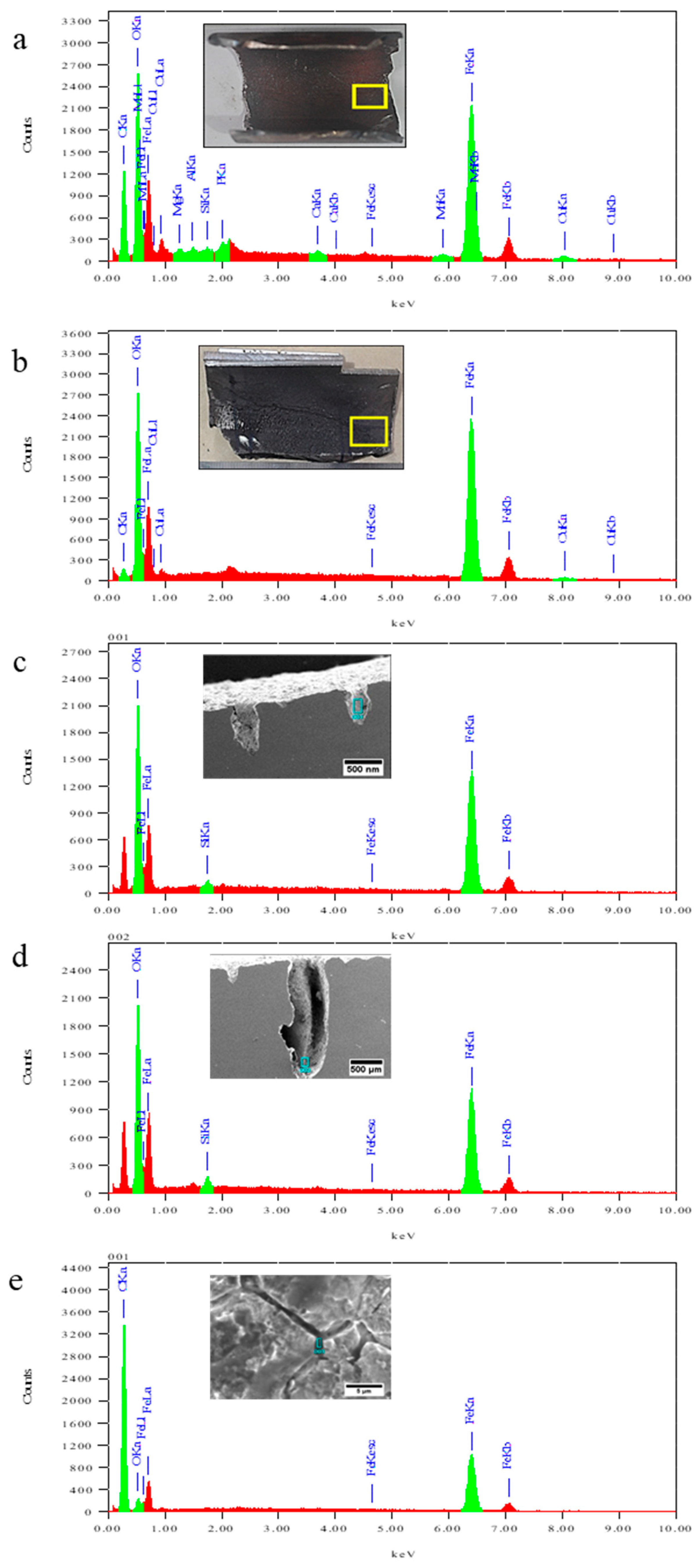
The EDS results and summary of elemental composition for each testing location (indicated by yellow and blue squares) are shown in Figure 9 and Table 4, respectively. EDS analysis result on the inner surface of the bottom part, which is an uncracked part and covered by a homogeneous and dense deposit structure (Figure 9a), showed that the original elements of the carbon steel tube (Mn, Si, Fe, P, and S) and its oxide layer (O) were observed in this area (Table 4). Interestingly, a significant amount of copper (2.16%) was observed in the deposit, not the elements of the carbon steel tube or its oxide layer.
EDS analysis result of the deposit at the corroded area, which is located on the inner surface of the top part of the tube (Figure 9b), revealed that the elements of the oxide layer (Fe and O) were dominant in this deposit (Table 4). Copper was also observed in this area, but its content (1.56%) was less than copper content in the bottom part (2.16%). Further discussion with the company revealed that the upstream surface condenser brass tubes were corroded [6,7]. The presence of copper deposits in a considerable quantity might be originated from these corroded brass tubes and the corrosion product mixed with boiler feedwater. The bottom’s deposit contains more copper than the top surface because water scale deposition preferentially occurred on the tube bottom. It is noteworthy that the deposit analysis on the inner bottom and the inner top surface was performed on as-received samples without a cleaning process (inset of Figure 9a,b). Thus, the presence of carbon in both samples originated from the black deposit that covered the surface of both samples.
Further EDS examinations were performed on the inside of the short crack (Figure 9c), long crack (Figure 9d), and grain boundary (Figure 9e) that were found around the leakage interface. EDS results unveiled that only Fe, Si, and O elements were found at the crack interface (Table 4), implying that the crack was filled by oxidation products, which is one characteristic of thermal fatigue was occurred in the leak site [21,22]. Since copper was not found at the crack interface and the grain boundary (Table 4), it can be concluded that copper on the surface was not penetrated the cracks and did not contribute to the formation of intergranular cracks. Thus, the intergranular crack formation was solely due to the hydrogen attack. It is worth noting that the deposit analysis on the short crack’s inner side, the long crack’s inner side, and the grain boundary were performed on samples after being mounted in polyester resin, followed by grinding and polishing. Thus, it is reasonable that the grain boundary sample has high carbon content (Table 4) because of polymer infiltration on the gap/cracks that were located on the surface, such as the crack in the grain boundary.
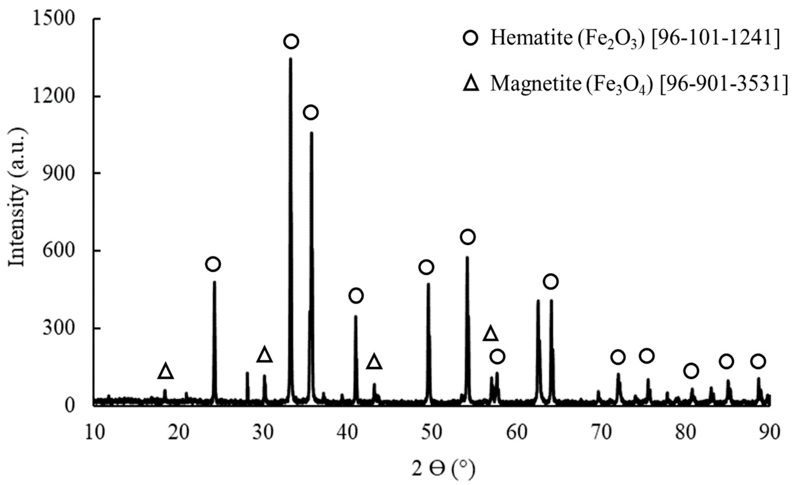
Additional characterization was performed on the corroded surface’s deposit using the X-ray diffraction (XRD) method to determine its compound type. As seen in Figure 10, the XRD result shows that the corrosion deposit on the inner surface was dominated by hematite (Fe2O3), with a small amount of magnetite (Fe3O4).

4. Discussion

4.1. Deposit Formation Mechanism

The boiler tube failed in the top part of the sloped tube, where half of the outer diameter was embedded in the castable insulation wall and hindered heat transfer. Furthermore, water splash could occur when water flow near the failed tube is located near the elbow, leading to water splash during Steam blanket initiated the deposit formation because of incomplete mixing between steam and water or the absence of turbulence flow due to low water velocity. Any water splash to the top part of the sloped tube would be evaporated. Solid particles in the water will remain on the top part of the tube wall during water evaporation and create a deposit, as confirmed by the EDS result (Table 4). The accumulation of these particles will produce a thick deposit on the upper part of the tube.
The steam blanket and deposit precipitation on the tube surface involve nucleation, evaporation, and partial or complete dissolution of the deposit [26]. The dissolution of the deposit from the surface occurs when the water flow is high enough to wipe it out. Howell presented a visualization of deposit formation by a steam blanket in horizontal and vertical/sloped tubes [27]. Most steam blanket phenomena occurred in sloped water tubes away from the radiant heat zone [28].
The steam blanket prerequisites are in boiler tubes under investigation, such as low heat input zone, mixing of steam and water, and sloped tube. EDS and XRD examinations revealed that the oxide layer on the tube’s inner surface is iron oxide (Fe3O4). This oxide contains micro-porosity (porous material) so that steam can penetrate the deposited layer and react with the iron substrate on the deposit-metal interface to produce hydrogen gas according to Equation (1) as follow [29]:
3 Fe (s) + 4 H2O (g) → Fe3O4 (s) + 4 H2 (g)
The above chemical reaction only occurs if the oxygen is absent because it will promote iron oxidation to Fe2O3 instead of hydrogen gas. X-ray diffraction analysis of the deposit on the inner tube surface revealed that the deposit is hematite (Fe2O3) instead of Fe3O4 because the tube sample has been exposed to oxygen in the atmosphere during handling, which oxidized the Fe3O4 deposit according to Equation (2) as follow [30]:
2 Fe3O4 (s) + ½ O2 (g) → 3 Fe2O3 (s)
Hydrogen gas in Reaction (1) will be absorbed by the tube surface and dissociate according to Equation (3) [31]. Then, hydrogen atoms diffused into grain boundaries to form hydrogen gasses and then reacted with cementite (Fe3C) in pearlite to produce methane gas (CH4) according to Equation (4) [32]:
H2 (g) ↔ 2 H (aq)
Fe3C (s) + 2 H2 (g) → CH4 (g) + 3 Fe (s)
Pearlite around the interface will be vanished and become a decarburized zone, as shown in Figure 7c. Trapped methane gas along the grain boundaries will create high pressure and break the grain boundaries to form fissures/micro-cracks along the grain boundaries [33]. Once enough fissures/cracks are formed, they begin to link (coalesce), severely weakening the tube wall and rupturing it even at normal working pressure.

4.2. Crack Propagation Mechanism

The crack propagation rate is strongly affected by the crack tip shape and geometry, where the sharp crack tip will accelerate crack propagation more than the blunt one. The sharp crack tip harms the structural component under stress because the stress concentration factor magnifies the local stress at the crack tips. The local stress will be much higher than the nominal stress because the stress concentration factor at the crack tips increases with the sharper crack tip.
Cracks morphology observed in a failed boiler tube consists of sharp and blunt crack tips. Figure 11 shows three different transgranular crack tips on the cracked boiler tube that will affect the crack propagation rate differently. Even though the crack morphologies are different, the failure mechanism for the three different cracks is the same (thermal fatigue and corrosion). However, it differs in the sequence of mechanism and proportion. The sharp crack (Figure 11a) was mainly caused by thermal fatigue. When the crack propagation is overwhelmed by corrosion, the crack site might be attacked and making it slightly blunt (Figure 11b). Moreover, if it is dominated by corrosion, the crack might become blunter, as seen in Figure 11c.
Considering the hoop stress from the operating condition (49.7 MPa) is significantly lower than the yield strength of the tube material (273 MPa; Table 3), and it is a static stress from the operating condition. Therefore, hoop stress is not considered a factor for thermal fatigue. The presence of sharp crack tip in the sample (Figure 7c and Figure 11) and the cracks were filled by oxidation product (Table 4), which are the typical characteristic of the occurrence of thermal fatigue, implying that thermal stress is the main driving force for crack propagation in this case. Thermal cyclic was developed when temperature decreased during water splashed and increased after water evaporation. Crack propagation occurred when the stress intensity factor at the crack tip exceeding the threshold stress for crack propagation [34] and stopped when the stress intensity factor was less. The stress intensity factor increases sharply with decreasing crack tip radius because the locally applied stress increases.
Corrosion and hydrogen attack modes on the crack tip occurred during idle time when the crack was stopped and would propagate again after the crack tip was sharpened so that the stress intensity factor exceeded the threshold stress for crack propagation. The crack’s initiation and propagation occurred intermittently until the crack was depth enough to reach the tube’s outer diameter.

5. Conclusions

The failure root cause of leakage in the bank-wall side boiler tube was a steam blanket that promoted the formation and accumulation of thick deposits on the top of the sloping tube’s inner surface. Crack initiation under the deposit was due to the combined effect of hydrogen attack and thermal fatigue.
The crack propagation consists of two parts; the first part is the fast crack propagation (transgranular cracks) due to thermal fatigue that started from high-stress concentration at the crack tips. The second part was slow crack propagation (intergranular cracks) because of under-deposit corrosion and was followed by a hydrogen attack.

Author Contributions

Conceptualization, H.A., A.R.S. and A.W.; Methodology, H.A., A.R.S., D.M.A. and A.W.; Project administration, H.A. and A.N.; Resources, A.N., M.H. and D.F.; Supervision, H.A.; Writing—original draft, H.A., A.R.S., D.M.A. and A.W.; Writing—review & editing, A.N., M.H. and D.F. All authors have read and agreed to the published version of the manuscript.

Funding

This research received no external funding.

Data Availability Statement

The data presented in this study are available on request from the corresponding author.

Acknowledgments

The authors would like to thank PT. Chandra Asri Petrochemical (Tbk) for providing tube specimens and the supporting data.

Conflicts of Interest

The authors declare no conflict of interest. PT. Chandra Asri Petrochemical (Tbk) was mentioned in this paper to describe the contribution of scientific information in the authors’ overall analysis. Any findings or conclusions stated in this paper are of the authors and do not represent PT. Chandra Asri Petrochemical (Tbk) in any capacity.

References

  1. Addel-Geliel, M.; Zakzouk, S.; Sengaby, M.E. Application of model based fault detection for an industrial boiler. In Proceedings of the 2012 20th Mediterranean Conference on Control & Automation (MED), Barcelona, Spain, 3–6 July 2012; pp. 98–103. [Google Scholar]
  2. Skiles, D. Improve the Performance of Your Boiler System. Chem. Eng. Prog. 2014, 11, 31. [Google Scholar]
  3. Sathish, T.; Mohanavel, V.; Afzal, A.; Arunkumar, M.; Ravichandran, M.; Khan, S.A.; Rajendran, P.; Asif, M. Advancement of steam generation process in water tube boiler using Taguchi design of experiments. Case Stud. Therm. Eng. 2021, 27, 101247. [Google Scholar] [CrossRef]
  4. Amir, M.K.; Samad, M.; Behzad, S.M.; Mehdi, S.M. Corrosion prevention in boilers by using energy audit consideration. In Proceedings of the Applied Mechanics and Materials, Zurich, Switzerland, 7–8 January 2014; pp. 307–310. [Google Scholar]
  5. Hong, M.; Chae, H.; Kim, W.C.; Kim, J.-G.; Kim, H.; Lee, S.Y. Failure Analysis of a Water Wall Boiler Tube for Power Generation in a District Heating System. Met. Mater. Int. 2019, 25, 1191–1201. [Google Scholar] [CrossRef]
  6. Ardy, H.; Putra, Y.P.; Anggoro, A.D.; Wibowo, A. Failure analysis of primary waste heat boiler tube in ammonia plant. Heliyon 2021, 7, e06151. [Google Scholar] [CrossRef]
  7. Ardy, H.; Nurimam, A.; Hamdani, M.; Abednego, T.H.; Helmy, R.K.; Bangun, D.A.; Setiawan, A.R.; Wibowo, A.; Sumboja, A. Failure analysis of admiralty brass tubes in a surface condenser: A case study at the petrochemical industry. Mater. High Temp. 2021, 38, 177–185. [Google Scholar] [CrossRef]
  8. Duarte, C.A.; Espejo, E.; Martinez, J.C. Failure analysis of the wall tubes of a water-tube boiler. Eng. Fail. Anal. 2017, 79, 704–713. [Google Scholar] [CrossRef]
  9. Liu, S.W.; Wang, W.Z.; Liu, C.J. Failure analysis of the boiler water-wall tube. Case Stud. Eng. Fail. Anal. 2017, 9, 35–39. [Google Scholar] [CrossRef]
  10. Asnavandi, M.; Kahram, M.; Rezaei, M.; Rezakhani, D. Fire-Side Corrosion: A Case Study of Failed Tubes of a Fossil Fuel Boiler. Int. J. Corros. 2017, 2017, 7367046. [Google Scholar] [CrossRef]
  11. Djukic, M.B.; Sijacki Zeravcic, V.; Bakic, G.M.; Sedmak, A.; Rajicic, B. Hydrogen damage of steels: A case study and hydrogen embrittlement model. Eng. Fail. Anal. 2015, 58, 485–498. [Google Scholar] [CrossRef]
  12. Dooley, R.B.; Bursik, A. Hydrogen damage. PowerPlant Chem. 2010, 12, 122. [Google Scholar]
  13. McCarroll, I.E.; Lin, Y.-C.; Rosenthal, A.; Yen, H.-W.; Cairney, J.M. Hydrogen trapping at dislocations, carbides, copper precipitates and grain boundaries in a dual precipitating low-carbon martensitic steel. Scr. Mater. 2022, 221, 114934. [Google Scholar] [CrossRef]
  14. Bose, S.; Reddy, S.; Singh, K. Interdependence of on-load corrosion, creep-rupture, and copper deposit in augmenting failure processes of boiler tubes. Corrosion 2000, 56, 1158–1169. [Google Scholar] [CrossRef]
  15. Daneshvar-Fatah, F.; Mostafaei, A.; Hosseinzadeh-Taghani, R.; Nasirpouri, F. Caustic corrosion in a boiler waterside tube: Root cause and mechanism. Eng. Fail. Anal. 2013, 28, 69–77. [Google Scholar] [CrossRef]
  16. ASTM A178-19; Standard Specification for Electric-Resistance-Welded Carbon Steel and Carbon-Manganese Steel Boiler and Superheater Tubes. ASTM International: West Conshohocken, PA, USA, 2019.
  17. ASTM E8/E8M-13a; Standard Test Methods for Tension Testing of Metallic Materials. ASTM International: West Conshohocken, PA, USA, 2001.
  18. ASTM E3-11; Standard Guide for Preparation of Metallographic Specimens. ASTM International: West Conshohocken, PA, USA, 2017.
  19. ASTM G131-96; Standard Practice for Cleaning of Materials and Components by Ultrasonic Techniques. ASTM International: West Conshohocken, PA, USA, 2016.
  20. Cai, G.; Li, C.; Wang, D.; Zhou, Y. Investigation of annealing temperature on microstructure and texture of Fe-19Cr-2Mo-Nb-Ti ferritic stainless steel. Mater. Charact. 2018, 141, 169–176. [Google Scholar] [CrossRef]
  21. Klobčar, D.; Kosec, L.; Kosec, B.; Tušek, J. Thermo fatigue cracking of die casting dies. Eng. Fail. Anal. 2012, 20, 43–53. [Google Scholar] [CrossRef]
  22. Klobčar, D.; Tušek, J.; Taljat, B. Thermal fatigue of materials for die-casting tooling. Mater. Sci. Eng. A 2008, 472, 198–207. [Google Scholar] [CrossRef]
  23. Zhan, J.; Li, M.; Huang, J.; Bi, H.; Li, Q.; Gu, H. Thermal Fatigue Characteristics of Type 309 Austenitic Stainless Steel for Automotive Manifolds. Metals 2019, 9, 129. [Google Scholar] [CrossRef] [Green Version]
  24. Bahrami, A.; Taheri, P. Creep Failure of Reformer Tubes in a Petrochemical Plant. Metals 2019, 9, 1026. [Google Scholar] [CrossRef] [Green Version]
  25. Kim, Y.S.; Kim, S.S.; Choe, B.H. The Role of Hydrogen in Hydrogen Embrittlement of Metals: The Case of Stainless Steel. Metals 2019, 9, 406. [Google Scholar] [CrossRef] [Green Version]
  26. Khajavi, M.R.; Abdolmaleki, A.R.; Adibi, N.; Mirfendereski, S. Failure analysis of bank front boiler tubes. Eng. Fail. Anal. 2007, 14, 731–738. [Google Scholar] [CrossRef]
  27. Howell, A.G. Under Deposit Corrosion Mechanisms in Boilers. In Proceedings of the CORROSION 2006, San Diego, CA, USA, 12–16 March 2006. [Google Scholar]
  28. DeWitt-Dick, D.B.; Beardwood, E.S. What Happens When Real World Operation of Steam Generators Deviates From Design Conditions. In Proceedings of the CORROSION 2008, New Orleans, LA, USA, 16–20 March 2008. [Google Scholar]
  29. Li, P.; Chen, Y.; Li, X.; Yan, B.; Chen, D.; Guo, H. Hydrogen generation characteristics of steel slag-steam high temperature reaction in terms of particle size. Int. J. Hydrogen Energy 2020, 45, 17140–17152. [Google Scholar] [CrossRef]
  30. Monazam, E.R.; Breault, R.W.; Siriwardane, R. Kinetics of Magnetite (Fe3O4) Oxidation to Hematite (Fe2O3) in Air for Chemical Looping Combustion. Ind. Eng. Chem. Res. 2014, 53, 13320–13328. [Google Scholar] [CrossRef]
  31. Yule, L.C.; Shkirskiy, V.; Aarons, J.; West, G.; Bentley, C.L.; Shollock, B.A.; Unwin, P.R. Nanoscale Active Sites for the Hydrogen Evolution Reaction on Low Carbon Steel. J. Phys. Chem. C 2019, 123, 24146–24155. [Google Scholar] [CrossRef] [Green Version]
  32. Cetinkaya, S.; Eroglu, S. Effect of the extent of pre-reduction of γ-Fe2O3 by H2 on the synthesis of Fe3C powder from CH4. Int. J. Miner. Process. 2016, 152, 46–52. [Google Scholar] [CrossRef]
  33. Martin, M.L.; Dadfarnia, M.; Orwig, S.; Moore, D.; Sofronis, P. A microstructure-based mechanism of cracking in high temperature hydrogen attack. Acta Mater. 2017, 140, 300–304. [Google Scholar] [CrossRef]
  34. Hertzberg, R.W.; Vincy, R.P.; Hertzberg, J.L. Deformation and Fracture Mechanics of Engineering Materials, 5th ed.; Wiley: Hoboken, NJ, USA, 2013. [Google Scholar]
Figure 1. (a) Schematic illustration of bank-wall side boiler tube and (b) location of the failed boiler tube.
Metals 12 02064 g001
Figure 2. Leak location inspection in the boiler tube using (a) hydrostatic test and (b,c) dye penetrant tests. The blue rectangle in (b) indicates the observation area of (c). the red arrow in (a,c) indicates the leak location.
Metals 12 02064 g002
Figure 3. Microstructure images of the uncracked parts of the tube at (a) low and (b) high magnifications.
Metals 12 02064 g003
Figure 4. Visual observation of the inner part located at (a) the bottom and (b,c) the top of the leaked boiler tube.
Metals 12 02064 g004
Figure 5. Fractography of corroded surface at the inner part of the top of the leaked boiler tube. (a) observation site (indicated by a yellow rectangle), (b) stereograph, (c) SEM micrograph.
Metals 12 02064 g005
Figure 6. (a) visual observation of the outer part of the leaked tube showing longitudinal leak location, (b) cross-section stereographs of the fractured surface, SEM image of: (c) transgranular cracks that were observed at the red rectangle area in (b), and (d) intergranular cracks were observed at the yellow rectangle area in (b). Red arrow in (c) and yellow arrow in (d) indicated the occurrence of transgranular cracks and intergranular cracks respectively.
Metals 12 02064 g006
Figure 7. Macro and micrographs of the corroded inner surface. (a) Sampling location, (b) stereograph of cross-section, (c) low magnification micrograph and observation site for further study (indicated by a red rectangle for the crack initiation site and yellow rectangle for near the crack tip), high magnification micrograph at (d) crack initiation site and (e) near the crack tip. Red arrow in (d) and yellow arrow in (e) indicated the occurrence of intergranular cracking and grain separation at the initial crack and near the crack tip respectively.
Metals 12 02064 g007
Figure 8. (a) stereograph of the leakage site and micrographs at (b) low magnification (at the red rectangle area in (a)), (c) high magnification (at the yellow rectangle area in (b)) showing the intergranular (red line) and transgranular (black line) cracks at the leak interface.
Metals 12 02064 g008
Figure 9. EDS analysis results of deposit at (a) the bottom and (b) the top surface of the tube; inside (c) the short crack and (d) the long crack; (e) on the grain boundary. Green and red peaks in EDS results indicated the X=Ray from K-alpha and K=beta emission respectively. Yellow rectangle in inset of (a,b), and blue rectangle in inset of (ce) indicating the EDS examination area.
Metals 12 02064 g009
Figure 10. XRD result of corrosion deposit.
Metals 12 02064 g010
Figure 11. Three types of crack tips morphology in the boiler tube.
Metals 12 02064 g011
Table 1. Operating conditions of bank-wall side boiler tube and the tube specification.
ParametersValuesUnit
Operating
condition
Maximum allowable working temperature371°C
Maximum allowable working pressure5.5MPa
Feedwater temperature at boiler inlet147°C
Water velocity1.0m/s
The tube
specification
Water-tube materialASTM A178 Gr. A
Outside diameter76.2mm
Thickness4.0mm
Table 2. Chemical composition of the boiler tube based on OES result (weight %).
Element
CSiSPMnFe
Sample0.0670.1210.0060.0260.495Balance
ASTM A178 Gr A [16]0.06–0.18…..≤0.035≤0.0350.27–0.63Balance
Table 3. Tensile test results of the boiler tube material.
SampleASTM A178 Grade A [16]
Tensile Strength, MPa380≥325
Yield Strength, MPa273≥180
Elongation, %42≥35
Table 4. Chemical composition of deposit (wt.%).
LocationElements
COMgAlSiPCaMnFeCu
Bottom31.4523.520.250.160.10.140.270.6941.262.16
Top5.0624.97 68.411.56
Short Crack 29.9 0.55 69.54
Long Crack 33.44 1.09 65.47
Grain boundary72.763.54 23.70
Publisher’s Note: MDPI stays neutral with regard to jurisdictional claims in published maps and institutional affiliations.