Abstract
As a clean and fuel adaptive alternative power plant, the Stirling power generating system has drawn attention of experts and scholars in the energy field. In practical application, the instability of free-piston Stirling power generating system caused by abrupt load change is an inevitable problem. Thus, methods to improve the output frequency response and stability of the free-piston Stirling power generating system are necessary. The model of free-piston Stirling power generating system is built by isothermal analysis firstly, and the initial control strategy based on given voltage system is put forward. To further improve the performance of power system, a current feedback decoupling control strategy is proposed, and the mathematical model is established. The influence of full decoupled quadrature-direct (d-q) axis currents is analyzed with respect to the output voltage adjusting time and fluctuation amplitude under the variations of piston displacement and output load. The simulation results show that the system performance is significantly improved, but the dynamic regulation lags caused by the decoupled current control still exist. To solve this problem and improve the performance of decoupled-state feedback current control that relies on parameter accuracy, internal model control based on sliding mode (IMC-SM) current decoupling control strategy is proposed, the system model is established, and then the performance of voltage ripple in generating mode is improved. Finally, the test bench is built, and the steady state and transient voltage control performances are tested. The feasibility and priority of the control strategy is verified by experiment and simulation results.
1. Introduction
With the increasingly severe situation of energy and environmental protection in the world, clean energy has become the focus of the research field in the new century, so the Stirling power generating system has attracted much attention. A free-piston Stirling engine [1,2,3] connected with a linear motor [4,5,6] converting mechanical power into electrical power, which implements thermo-mechanical-electrical energy conversions, is called a free-piston Stirling power generating system. The combination of free-piston Stirling power generating system and linear motor formulates the thermo-mechanical-electrical system [7,8,9,10], which carries forward the advantages of both. Energy conversion efficiency and the reciprocating oscillation amplitude stability of free-piston Stirling generating system are ensured by dynamic and thermodynamic research with respects to model simulation analysis, parameter optimization, and system integration debugging. Amplitude and frequency stability of free-piston generating system is difficult to realize in practical work, and the unstable characteristic caused by the variation of output load is inevitable. Effective control strategy is studied to improve the robustness of the generating system to meet the demands of the generating process and improve the stability of the output current of free-piston Stirling generating system [11,12,13,14].
Scott S Gerber proposed a hierarchical control scheme for the Stirling power generation system, which is divided into three layers: energy management layer, air fuel ratio control layer, and linear motor trajectory control layer [15]. Pavel Němeček and his fellows in Czech Technical University proposed a double stroke Stirling generating system scheme, adopting new type circuit to achieve energy conversion to realize steady control under generating state [16]. The control method proposed by American scholar Raymond L Kirby combines the characteristic of output stroke and load, which is able to control fuel consumption by controlling the output of current [17]. The Monrovia company Zaher Daboussi proposed a linear motor rotor position detection method of Stirling power system, preventing over stroke by controlling the displacement of free-piston via the back electromotive force (EMF) [18]. However, the estimation of phase and voltage lends to negative effects on control accuracy.
Steady control of free-piston Stirling power generating system under the variation of out load is a study emphasis of this paper. With the benefits of simple structure and easy realization, current-stroke and current-voltage double closed-loop control strategies [19,20,21,22] are employed in traditional free-piston power generating system, which ignored the d-q axis current coupling problem. Current feedback decoupling control strategy is investigated to realize the d-q axis current full coupling of motor control system. The influence of d-q axis decoupled state current is studied with respect to the output voltage adjusting time and fluctuation amplitude under the variations of piston displacement and output load. Simulation results show improved results compared with the initial double closed loop control. With regard to the dynamic regulation lag in the decoupled current caused by system parameter variations, an internal model control based on sliding mode IMC-SM is proposed, which improves the performance of the decoupled-state feedback current control that relies on system parameter accuracy, and further reduces output voltage ripple in generating mode by simulation comparison and analysis.
2. Free-Piston Stirling Power Generating System Model
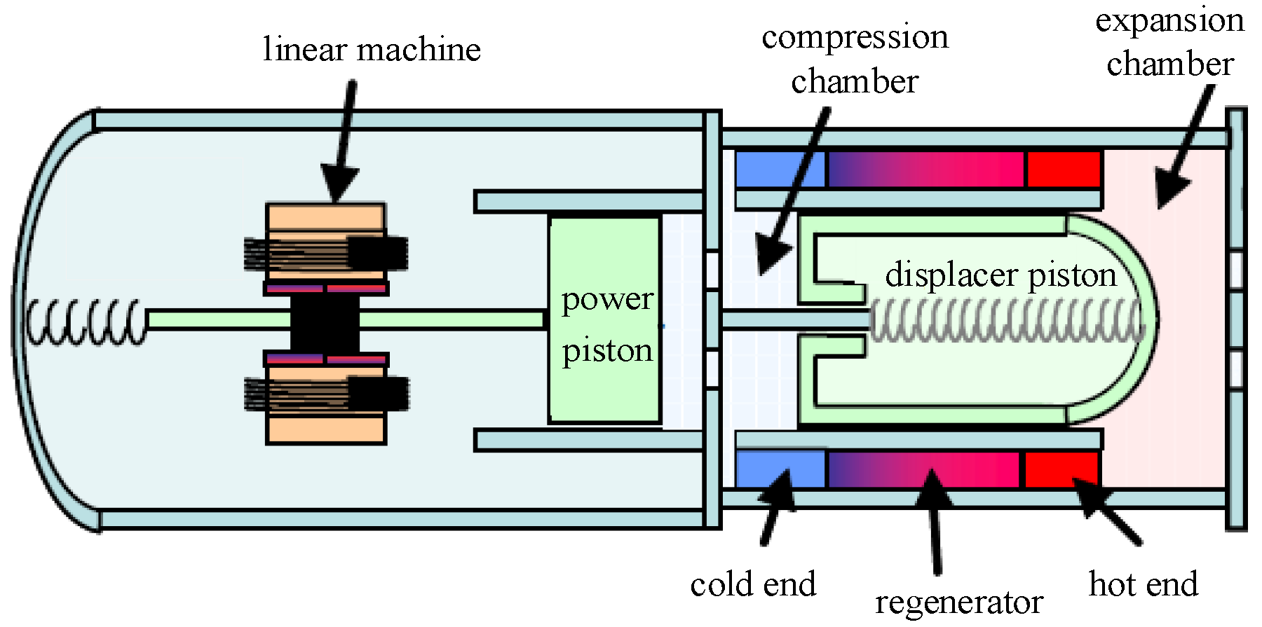
Free-piston Stirling power generating system is a two-degree-of-freedom vibration system working in resonant state, and is composed of free-piston thermal cycle power system and cylindrical permanent synchronous linear motor power generating system that works in interrelated and mutual influenced condition. The structure of free-piston Stirling power generating system shown in Figure 1 is a two-degree-of-freedom mass-stiffness-damping system (generally considered to be fixed housing) [23,24]. Main factors affecting the stability of the system are stiffness of air spring, regenerator damping, piston phase position, motion frequency, hot and cold cavity volume and structure. Kinetics research of Stirling generating motor starts with the foundation of preliminary mathematical model, with respect to its structure parameters and performance characteristics, to form the preliminary design criteria of the system by characteristic simulation analysis of the model.
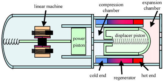
Figure 1.
Structural schematic diagram of free-piston Stirling power generating system.
The starting process of free-piston Stirling power generation system is: at the initial stage, the moving parts are in equilibrium and at rest. With the temperature of the hot end rising, expansion chamber gas pressure increases, leading to , and it can be seen in Figure 1 that displacer piston and power piston move left. The acceleration of displacer piston is much greater than power piston, the mass of whom is several times that of displacer piston, leading to the volume of cold cavity between power piston and displacer piston decreases, and the gas pressure also rises on account of gas flew from cold cavity to hot cavity. In the reverse (right) motion, the acceleration of displacer piston is much greater than power piston, which leads to gas flowing from hot cavity to cold cavity and further causes the decrease of gas pressure. The piston moves in cycles back to the equilibrium position after certain distance away caused by the existence of elastic force, and the system achieves dynamic balance in the starting process.
The free-piston Stirling power generating system consists of motor housing, displacer piston and power piston. The mass of displacer piston and power piston is much less compared with motor housing, thus the movement of displacer piston and power piston is the main consideration while the movement of the housing can be neglected. The pressure difference between the two ends of the piston forms the force acting on the piston, the dynamic equation of which is obtained according to Newton’s second law (taking the equilibrium position as zero point, and right as the forward direction):
Similarly, the dynamic equation of power piston is (taking the equilibrium position as zero point, and right as the forward direction):
represent gas pressure of spring chamber, buffer chamber, compression chamber and expansion chamber, respectively.
are the cross-sectional area of power piston, displacer piston and the rod in the center of displacer, respectively.
, are the mass of power piston and displacer piston, respectively.
Equations (1) and (2) are dynamic equations coupled with thermodynamics and dynamics. is electromagnetic thrust for permanent magnet synchronous linear motor [25] expressed by the equation below:
are electromagnetic thrust and mechanical force, respectively; and is mover mass.
The inductance of d-q axis is considered to be approximately equal to simplify the analysis, and the equation of electromagnetic thrust is:
Electromagnetic thrust control is realized by adjusting the current (expressed by ) of q axis, which is linear dependent with electromagnetic thrust when the linear motor works at rated thrust.
When the hot end and the cold end are controlled by constant temperature difference, the relationship equation of the output power and thrust of free-piston Stirling motor are:
is linear motor output power, is the average pressure of working gas in Stirling power generation system, is the amplitude of displacer piston, is the temperature ratio of hot end and cold end, and are power ratio and equivalent damping coefficient, respectively.
Parameters and are definite values in Stirling power generating system design. The amplitude of displacer piston is controlled by stroke controller to derive power matching of motor and the load.
3. Control Strategy of Free-Piston Stirling Power Generating Motor
3.1. Double Closed-Loop Generation System Control Strategy
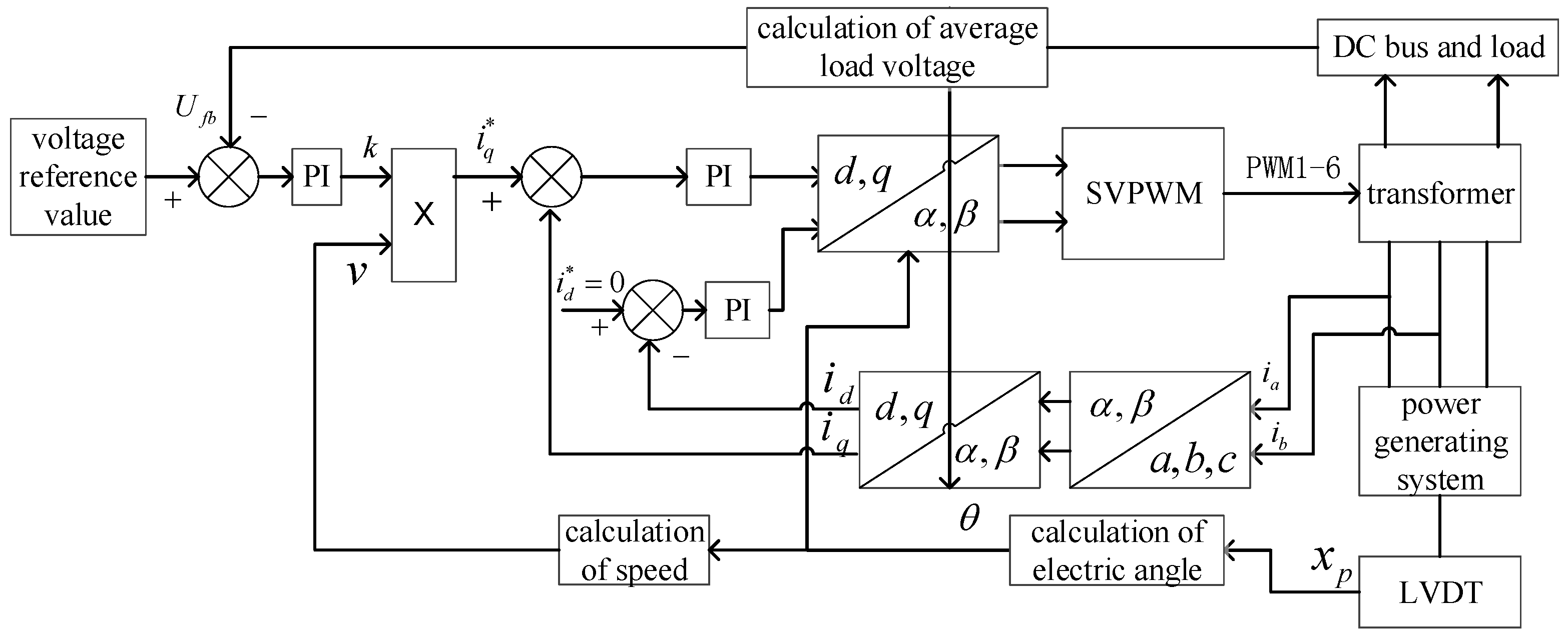
The double closed-loop generation system control strategy shown in Figure 2 is a traditional and fundamental strategy which is widely adopted nowadays. Current input reference value is composed of speed correlative and position correlative, and the output k of voltage controller is modulation index. When the engine starts from rest, fixed thrust of the motor deviates the piston from equilibrium position firstly, then it releases, which starts the oscillation process. The voltage reference value is greater than voltage feedback value , and the output of voltage controller (i.e., motor thrust coefficient) k is positive, and the direction of is the same with piston velocity, thus the output thrust of the motor is positive, which increases the motion amplitude of the piston and the feedback of motor in electric state. When the piston oscillation amplitude amounts to a certain value, voltage feedback value becomes greater than reference value, k decreases to negative, and the direction of becomes opposite to piston velocity. When output damping emerges, the motor works in generation mode, and motor thrust coefficient k varies with feedback voltage: the rise of k causes the thrust of motor increasing when voltage is low, thus the voltage rises on account of the increase of piston amplitude and output power. The decrease of k causes the thrust of motor reducing when voltage is high, thus the voltage reduces due to the decrease of piston amplitude and output power. In the stroke adjustment process, when the power generated is greater than require, the excess energy is released to the energy storage capacitor and leak resistor, otherwise energy storage capacitor provides energy to the load.

Figure 2.
Block diagram of double closed-loop generation system control strategy.
3.2. Control Strategy Based on Decoupling of Current Feedback
Output voltage adjusting time, the voltage (power) fluctuation amplitude, the following performance of d-q axis current under the variation of piston displacement, output voltage ripple and load need to be improved. is adopted in traditional vector control strategy, and PI regulator controls d-q axis current feedback. The traditional method is easy to implement, but the current coupling problem is neglected. To improve the dynamic and the static performance, the current feedback decoupling control strategy is studied. In current feedback decoupling control strategy. Through the d-q axis feedback current, the speed input to the feedback decoupling unit, the decoupling of d-q current loop [26,27,28] is realized. The d-q axis voltage equation of permanent synchronous linear generator is:
are stator voltage components of d-q axis; are stator current components of d-q axis; are back EMF components, and , ; are inductance components, is permanent magnet flux; is mover velocity of linear motor; is motor wire-wound resistor; and is pole pitch of linear motor.
According to the equation above, d-q axis is coupled when PI control strategy is adopted, in order to counteract back EMF output voltage and control current of d-q axis, adjusting time is prolonged and the performance of generating system is affected.
Current feedback decoupling control strategy is shown in Figure 3. If d-q axis realizes full decoupling, then:
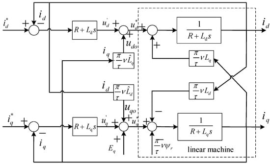
Figure 3.
Control strategy based on decoupling of current feedback.
udo, uqo are voltage compensation rates of d-q axis; is q-axis back EMF compensation term; and are the estimated values of .
If , then voltage equation of the current regulator d-q axis is shown in Equation (11). With d-q axis seen as two separate linear subsystems, full decoupling controlled is realized.
The d-q axis magnitude of current of linear motor is obtained by Clark transformer and Park transformer. The value of signal is the referenced current value of q-axis, which bus voltage is passing through PI multiply by speed signal. Voltage control signal of space vector pulse width modulation (SVPWM) generator drives the three-phase half bridge, realizing the rectification control of linear motor. The dynamic performance of vector control system is improved by adding the current feedback decoupling unit.
3.3. Optimal Decoupling Control Strategy Based on IMC-SM
Current feedback decoupling control strategy relies on parameter estimation accuracy, because of which the error exists in parameter estimation under normal circumstances, and the motor parameters vary with stator current and motor frequency. Parameter estimation error causes compensation errors and to deviate greatly, which delays the current dynamic change of d-q axis and affects the performance of current decoupling control strategy. IMC-SM proposed in this section reduces the dependence of current decoupling on parameter accuracy and improves the quality of voltage ripple in generating mode.
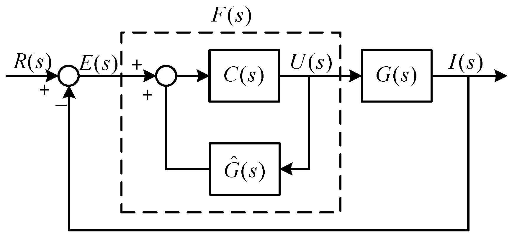
Internal mode current feedback control principle is shown in Figure 4, where internal mode is , and controlled plant is . Permanent magnet synchronous motor voltage and current are and , respectively. is represented current. is internal controller. Equivalent transfer function of internal control principle is a classical controller, relating to and .
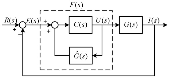
Figure 4.
Schematic diagram of IMC.
By Equation (11), if d-q axis current realizes full decoupling, then
Let , , . And is a low pass filter as shown in Equation (14). Its transfer function has no zero point in the left-half plane of complex plane, which improves the robustness of the system.
and can be written as:
Then, the transfer function becomes
The system is affected by it in practical use; the robustness of system is promoted by importing sliding control. In sliding mode, the sliding surface of d-q axis current is defined. Take q-axis for example:
is the q-axis voltage of IMC.
To avoid approaching motion, the state trajectory is confined to the sliding surface to keep favorable robustness during the motion process. According to the derivation result of Equations (8) and (17) and the Lyapunov stability criterion, the following relational expression is obtained.
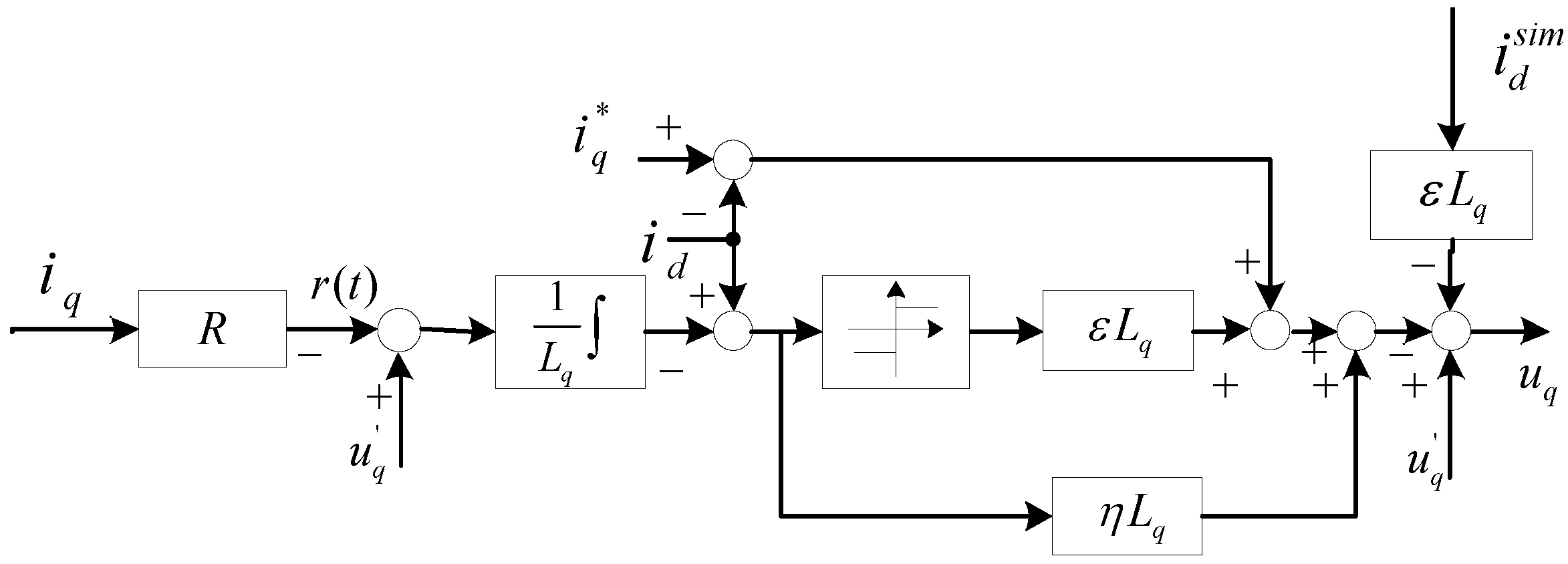
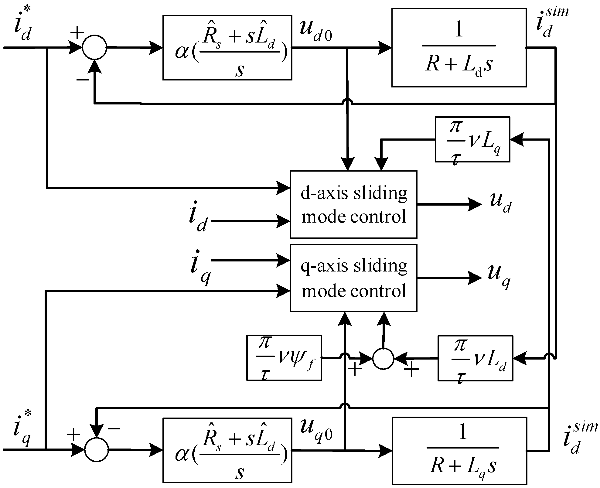
and are demanded to ensure the effectiveness of sliding mode control of q-axis and the stability of the system. Sliding mode control of q-axis current (SMC-q) principle is shown in Figure 5. The decoupling control strategy is shown in Figure 6.
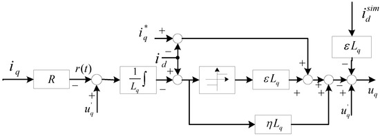
Figure 5.
The q-axis current diagram of SMC.
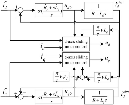
Figure 6.
Optimized IMC-SM control based on decoupled current.
4. Simulation Research
System basic parameters shown in Table 1 are based on model analysis of free-piston Stirling generating system. Simulation analysis on the stability problems of voltage ripple in generating mode and the voltage regulation capability with load mutation is carried out.

Table 1.
Basic parameters of free-piston Stirling power generating system.
Simulation analysis on the performance of free-piston Stirling generating system control strategy is carried out. At 1 s, 2 s and 3 s, DC bus resistance loads of 150 Ω (underload), 100 Ω (rated load), 50 Ω (overload) are connected sequentially to the system, and the data of displacer amplitude, output load, current and power are observed when the load mutates. The output power of linear motor is supposed to increase in turn according to the connection sequence of the resistance loads under average DC output voltage of 100 V. Accordingly, the power range of the linear motor in generating mode is obtained.
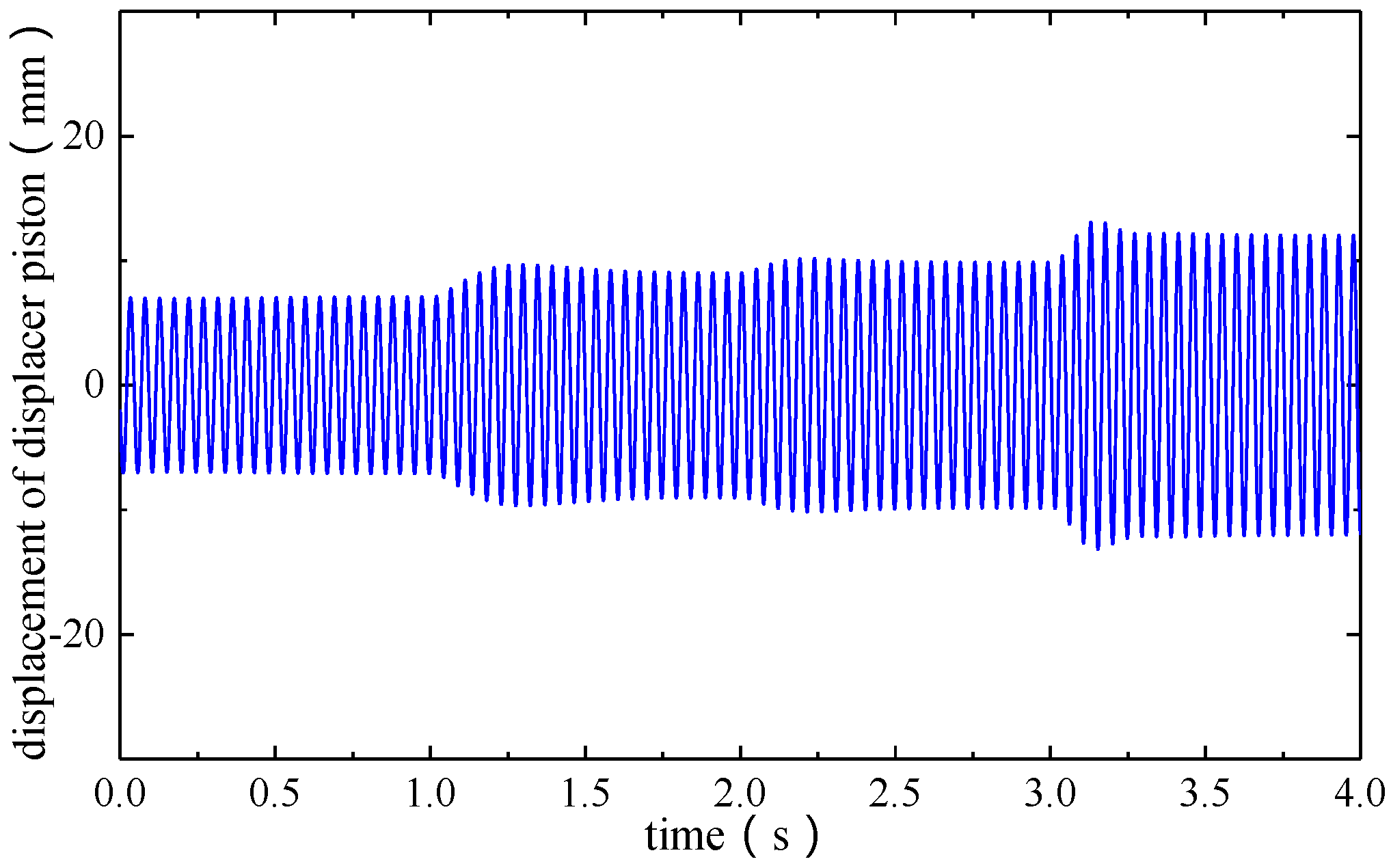
Simulated piston displacement for three different control strategies is shown in Figure 7. From 0 s to 1 s, motor is under the state of no-load, and the piston amplitude is 7 mm. The output power of motor increases with the connection of 150 Ω resistance load at 1 s, the amplitude of piston amounts to 9 mm and remains stable in the following several strokes. The situations when 100 Ω and 50 Ω resistance loads are connected at 2 s and 3 s are similar to that at 1 s.

Figure 7.
Piston displacement for different resistances.
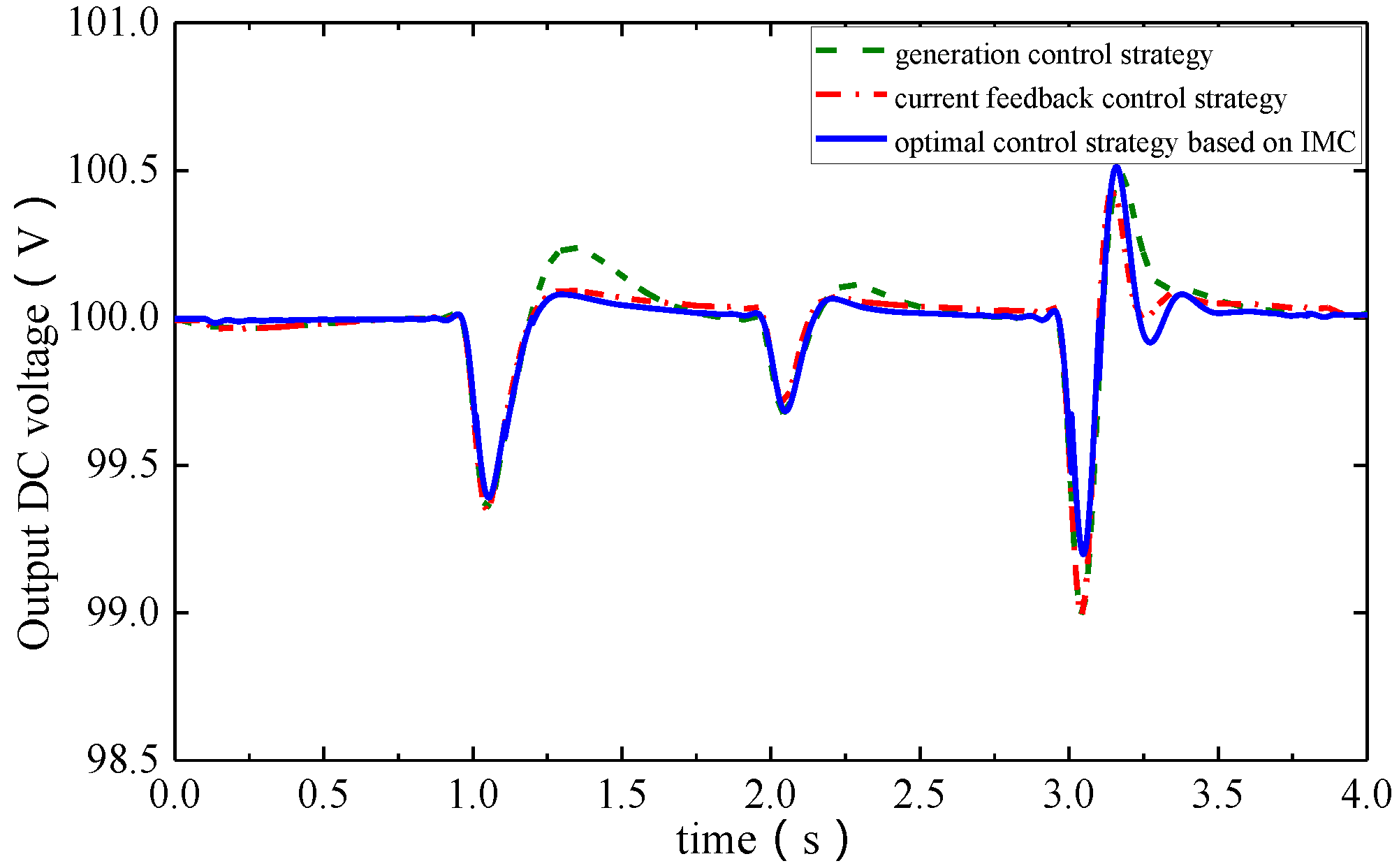
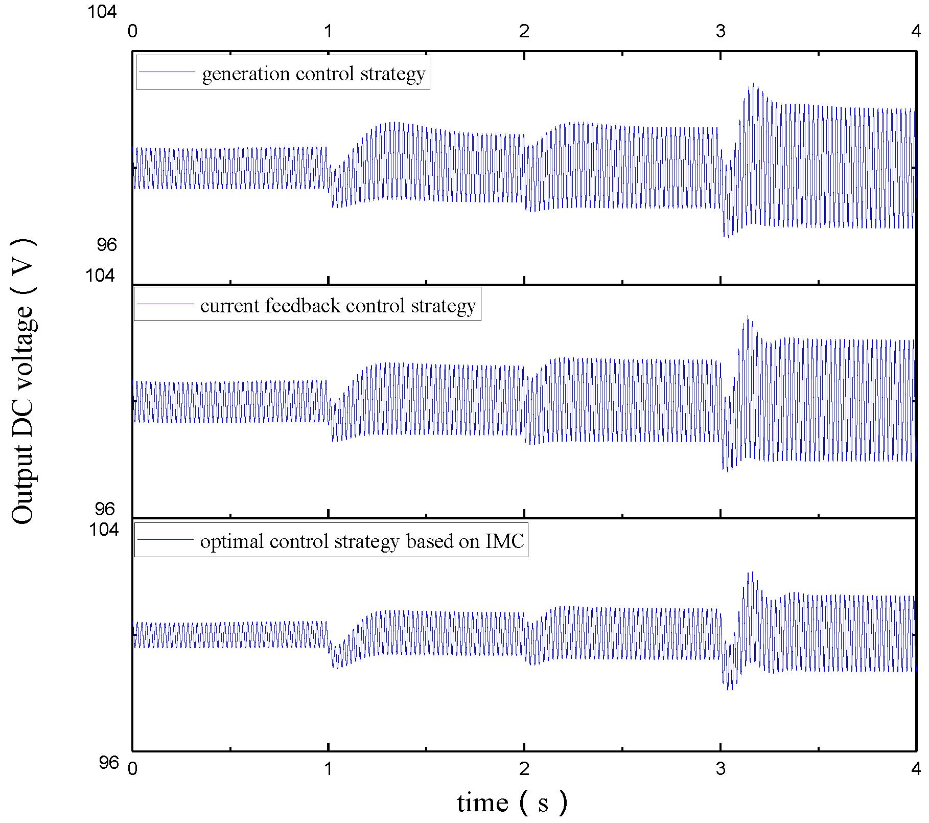
The simulation results of three different control strategies are compared. Figure 8 shows the output voltage comparison of three different control strategies. Figure 9 illustrates the average output voltage comparison of three different control strategies. Voltage ripple under the load of 100 Ω in generating mode is shown in Figure 10.
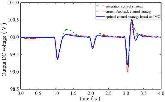
Figure 8.
Comparison of mean voltage of three control strategies.

Figure 9.
Comparison of load voltage of three control strategies.
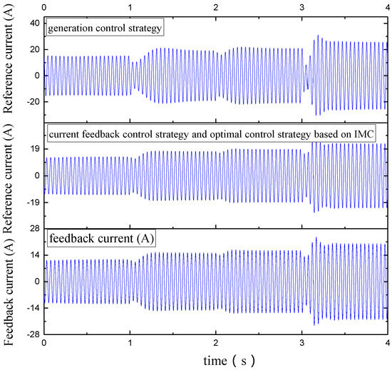
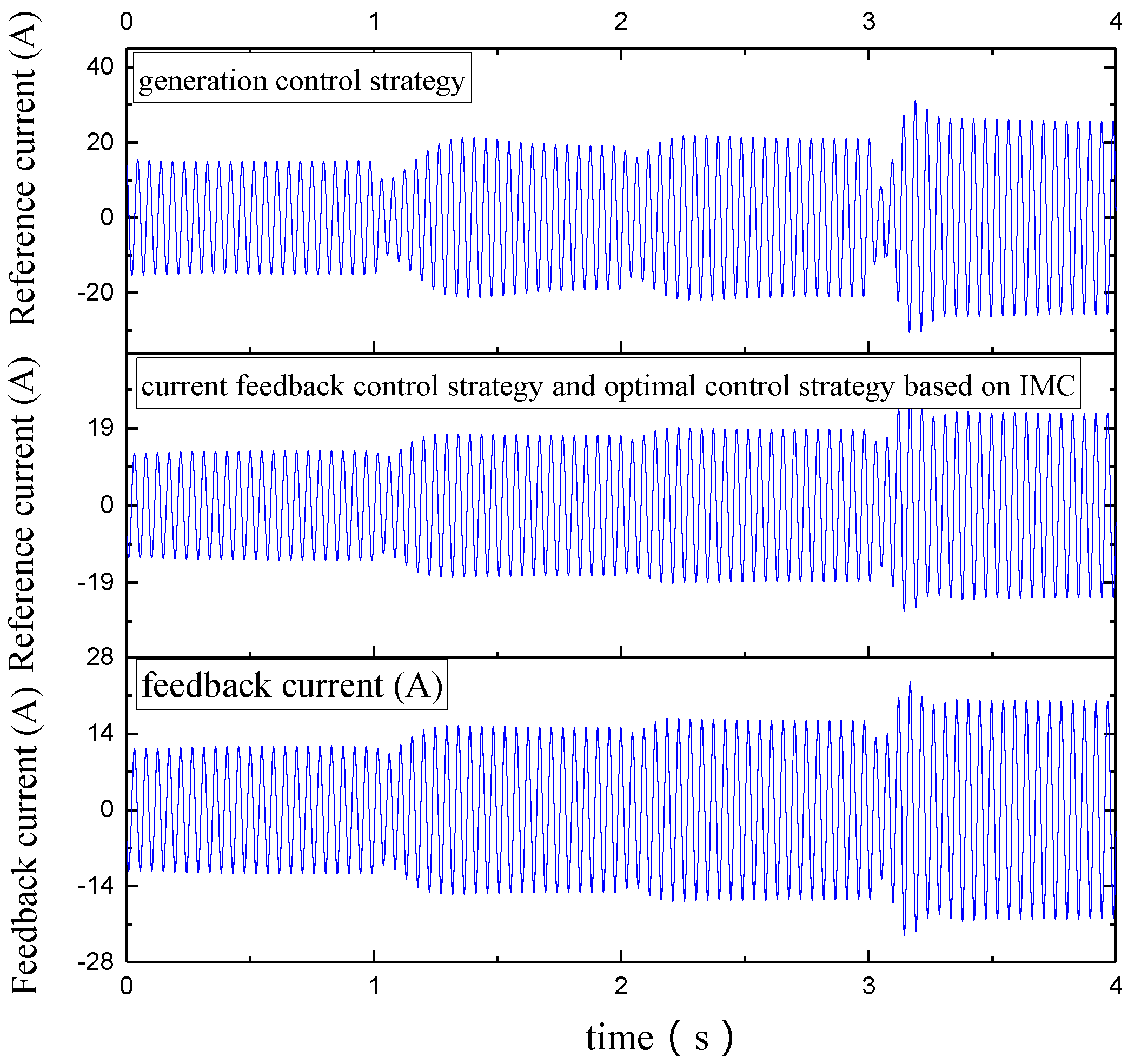
Figure 10.
Comparison of q-axis reference current and feedback current of different control strategies.
In Figure 8 and Figure 9, voltage ripple (0.5%) based on IMC-SM control strategy reduces compared with the original generation control strategy (0.8%) and current decoupled control strategy (0.7%) in no-load stage. Take 100 Ω load for example, voltage ripple (0.9%) based on IM-SMC control strategy is smaller than original generation control strategy (1.4%) and current decoupled control strategy (1.3%) in Figure 8, which means the performance of voltage ripple based on IM-SMC control strategy is optimal.
The voltage ripple amplitude with load mutation is shown in Figure 8 and Figure 9. When the load state changes from no load to 150 Ω resistance load connected, the maximum voltage ripple of original generation control strategy is 1.8%, while that of decoupled current control strategy is 1.2% compared to that based on IM-SMC control strategy is 0.9% which is better than the two. As resistance load decreases from 150 Ω to 100 Ω, the voltage ripples of original generation control strategy, decoupled current control strategy and the control strategy based on IM-SMC are 1.7%, 1.4% and 1.2% respectively, which shows that decoupling control strategy is superior than the other two. As resistance load decreases from 100 Ω to 50 Ω, the maximum voltage ripple of control strategy based on IM-SMC is 2%, which is less than that of original generation control strategy and decoupled current feedback control strategy, 2.8% and 3% respectively.
The adjusting time with load mutation is shown in Figure 8 and Figure 9. The adjusting time of original generation strategy, decoupled current feedback strategy and strategy based on IM-SMC is 0.75 s, 0.6 s and 0.6 s, respectively. As resistance load decreases from 150 Ω to 100 Ω, the adjusting time of original generation strategy, decoupled current feedback strategy and strategy based on IM-SMC is 0.5 s, 0.4 s and 0.4 s, respectively. As resistance load decreases from 100 Ω to 50 Ω, the adjusting time of original generation strategy, decoupled current feedback strategy and strategy based on IM-SMC is 0.7 s, 0.6 s and 0.6 s, respectively. Based on the analysis above, the adjusting time of current feedback control strategy and the strategy based on IM-SMC under different loads are similar, which are better than the original strategy.
The d-q axis current following performance of current feedback decoupling and optimal decoupling based on IM-SMC are approximately equal. The comparison of decoupled feedback and original generation control strategy is shown in Figure 10. The reference value of generation control strategy is 30.05% which is larger than that of feedback current, as that of decoupled control strategy is 14.22% in no-load stage. In load (100 Ω) stage, the reference value of generation control strategy is 30.69% larger than that of feedback current while that of decoupled control strategy is 13.63%. The output of d-q axis regulator transfers to compensate voltage, and current loop id, iq are decoupled to improve the following performance of q-axis current. Decoupled current feedback control strategy is superior to that of generation control strategy in promoting the following performance of current.
Decoupled current feedback control strategy is superior to generation control strategy in promoting voltage adjusting time, voltage ripple amplitude with load mutation and the following performance of current. Compared to the decoupled current feedback control strategy, optimal decoupled current control strategy based on IM-SMC significantly improves the voltage ripple in generating mode and the voltage amplitude with load mutation. Overall, the performance of free-piston Stirling generating system is promoted by optimal decoupled current control strategy based on IM-SMC.
Since the performance of the power generating system in the process of load mutation is relatively concerned, the system is simulated under three different control strategies and the results are compared with the displacement of displacer piston, output voltage ripple amplitude, adjusting time (response speed) and voltage ripple amplitude under different resistance loads, and the following performance of d-q axis current is shown in Table 2. (Take the load stage of 100 Ω for example, no-load regulation means load stage changing from no-load to 150 Ω resistance load, and load regulation means load state changing from 150 Ω to 100 Ω resistance load.)
Table 2.
Simulation results comparison of three control strategies.
5. Experimental Verification
5.1. Experiment Platform
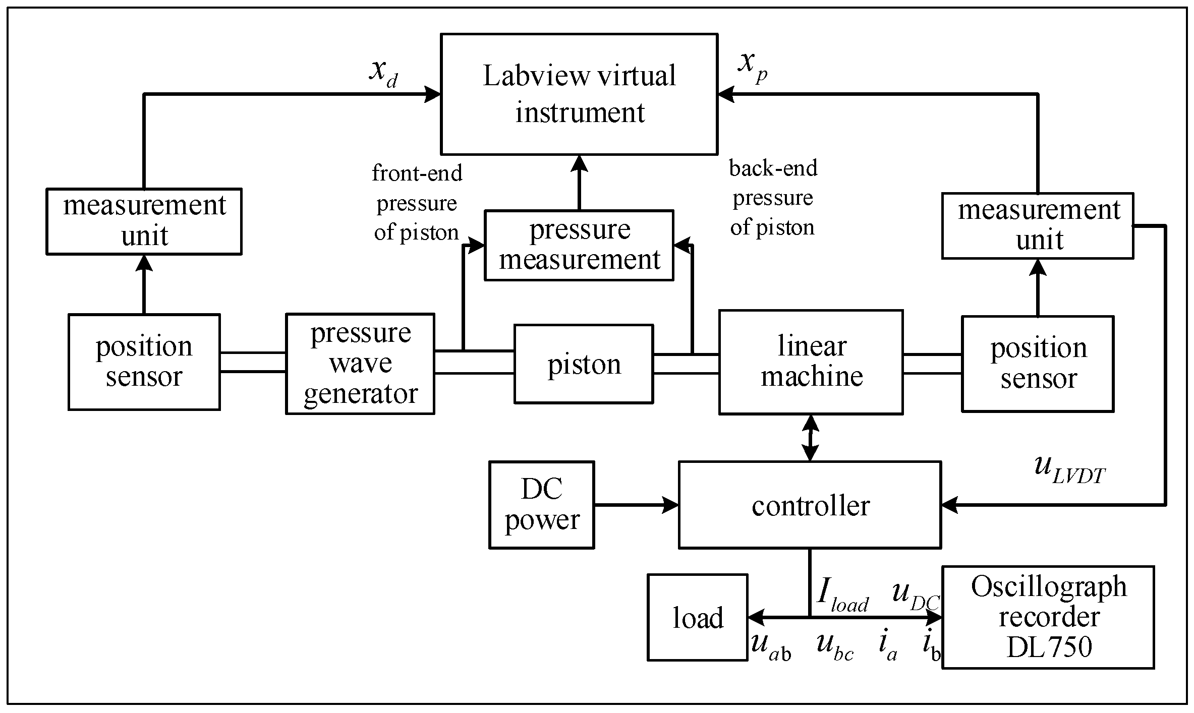
Test platform of the power generating system shown in Figure 11 shows the specific process of the system: the motion components inside the pressure wave generator produce a linear reciprocating motion with external gas source, and the internal piston drives the linear generator for reciprocating motion, then through the pressure sensor the pressure at both ends of the piston is collected to calculate the pressure difference to get generator thrust. The mover position is obtained by the displacement sensor, and the information such as the speed and frequency of the generator mover can be obtained by processing the position signal. In the electric state, the controller is used to start the pressure wave generator. In the power generating state, the controller can manage the electric energy to improve the system performance. The power generating system performance parameter information is recorded and stored by the oscilloscope.
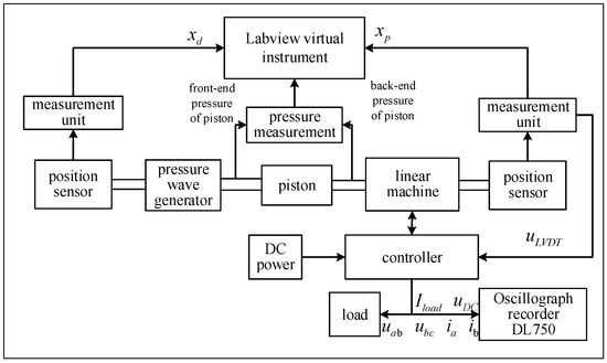
Figure 11.
Test platform of the power generating system.
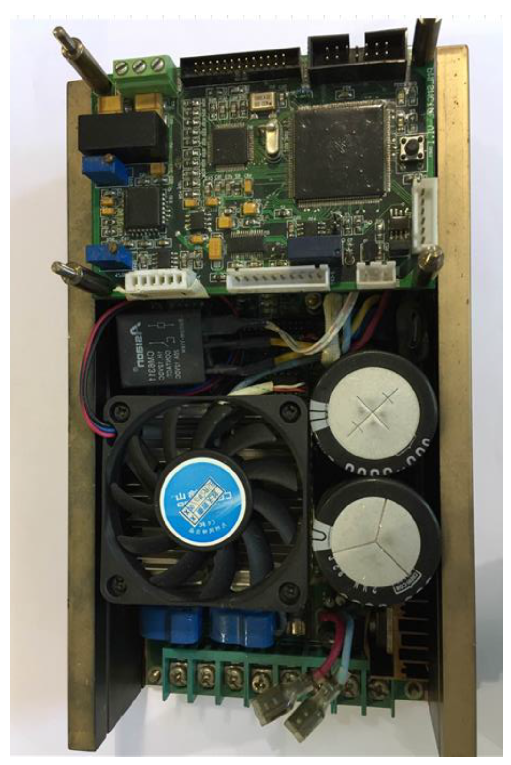
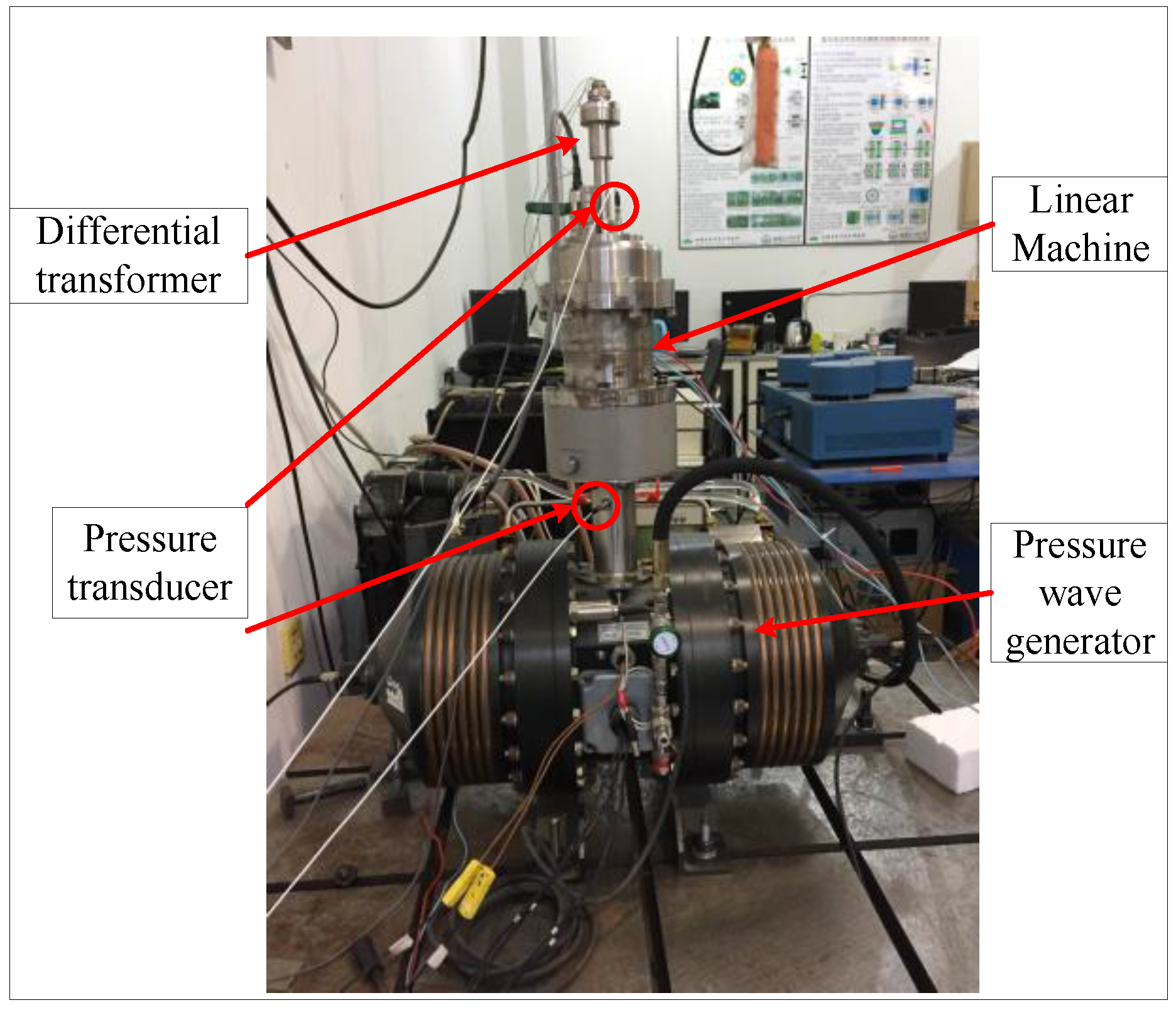
Photo of the controller is shown in Figure 12, and test platform photo of power generating system covering the main equipment is shown in Figure 13.

Figure 12.
Photo of the controller.
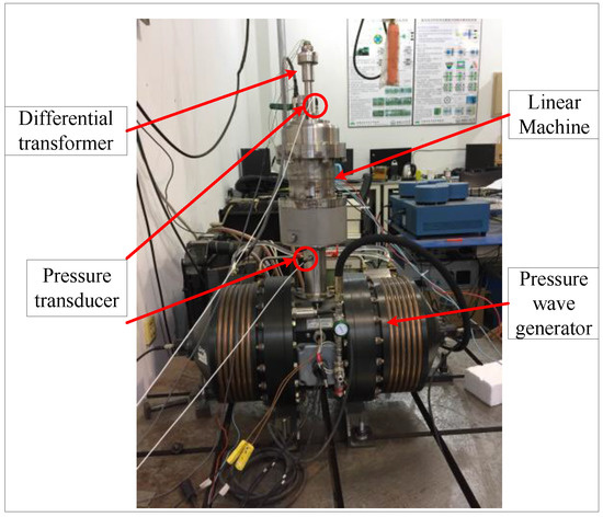
Figure 13.
Test platform photo of power generating system.
Structure parameters of linear machine are shown in Table 3.
Table 3.
Structure parameters of linear machine.
5.2. Experimental Results
5.2.1. Steady State Experiment
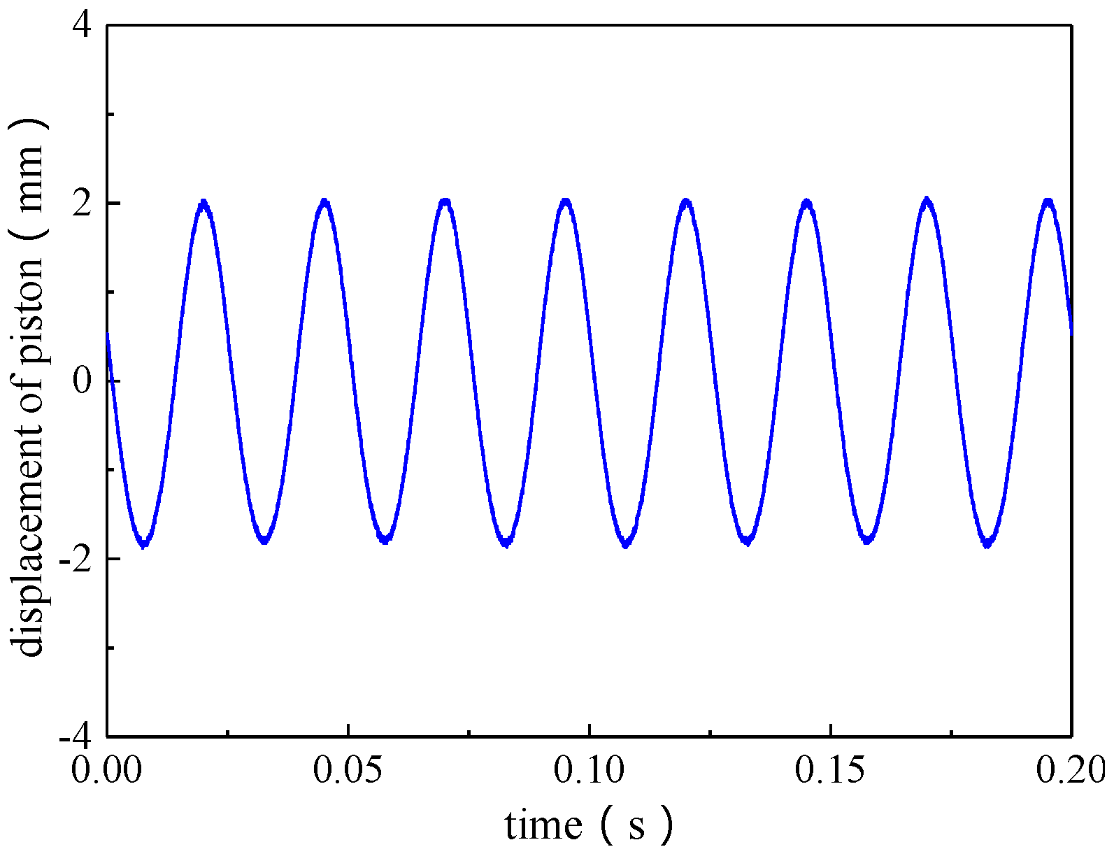
Figure 14 shows the displacement waveform after the system enters the stable power generation stage. At this time, the stroke of the piston is 4 mm, and the stroke of the piston is stable. Steady-state power bus voltage is shown in Figure 15. The voltage value is between 47.5 V and 49 V, and the reference value is 48 V, indicating the two coincidences as well. Output current waveform is shown in Figure 16. When the amplitude is between 0.21 A and 0.24 A, the steady-state power output reaches the maximum value of 11.76 W.
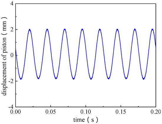
Figure 14.
Piston displacement waveform during steady state generating test.
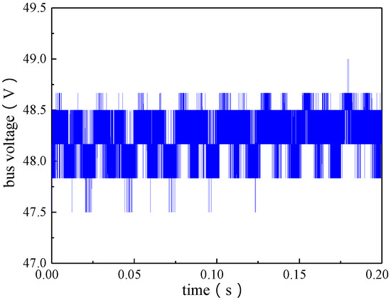
Figure 15.
Bus voltage waveforms during steady state generating test.
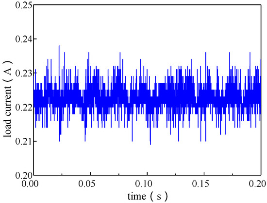
Figure 16.
Output current waveforms during state generating test.
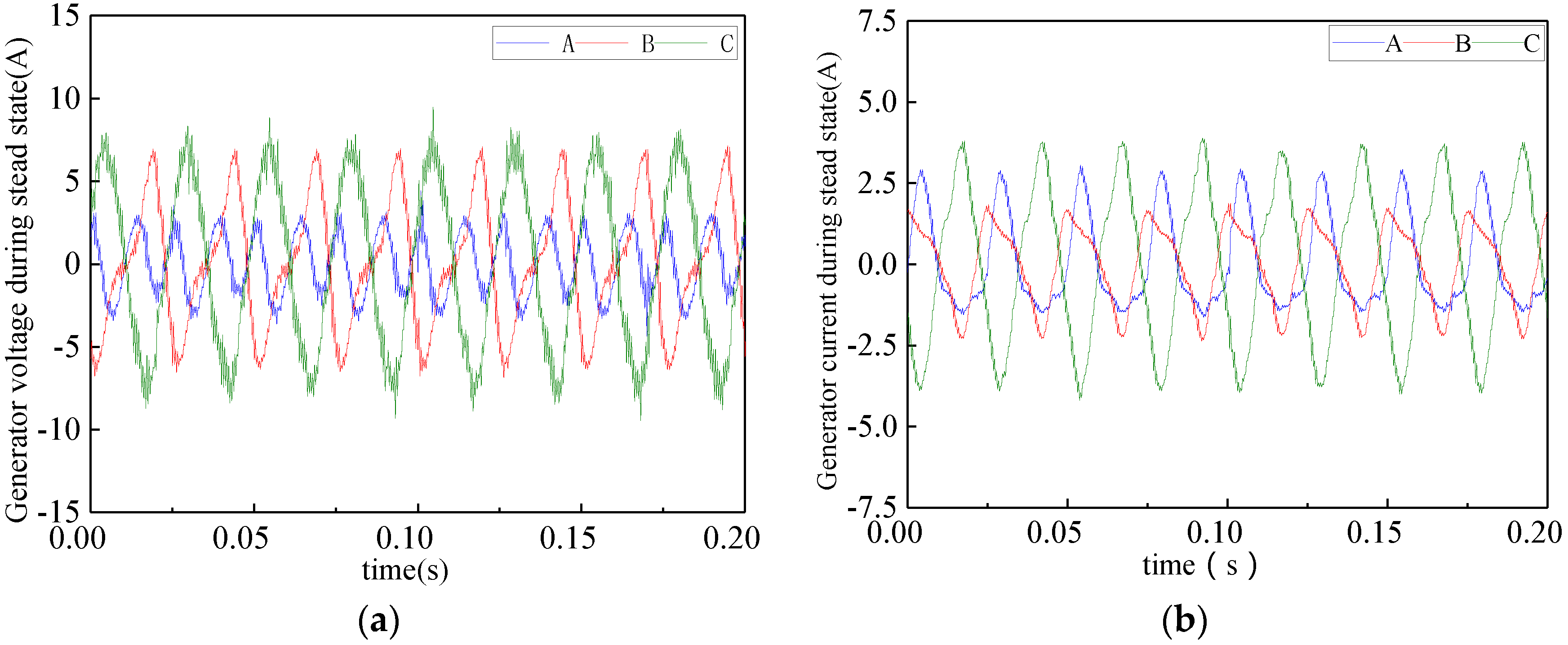
The output voltage and current of the generator when the power generating system is in steady state are shown in Figure 17a,b.
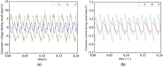
Figure 17.
Generator voltage waveforms and current waveforms during steady state generating test: (a) generator voltage waveforms; and (b) generator current waveforms.
It can be seen from the experimental results that the piston stroke is stable during the stable generation of the power generating system; the output bus voltage is basically the same as the reference value; and the ripple is very small, which proves that the power generating system has good steady-state power generation performance. As can be seen in Figure 17, the amplitude of the back electromotive force of the A and B phases of the motor is significantly smaller than that of the C phase, which is due to the influence of the end effect.
5.2.2. Transient Experiment
To verify the effectiveness of the power generating control strategy, Figure 18 shows the piston displacement waveforms with variable load during generating test. The figure shows that the piston stroke is approximately 4.5 mm when the system is stable. When the power generation continues stably about 25 s, the load resistance is increased, which decreases the stroke of the piston. After 5 s of adjustment, the power generating system reaches a new steady state, where the piston stroke is about 3.2 mm. When the system is stable in generation state for 10 s, the load resistance is restored to the initial value. The stroke of the piston is gradually steady, basically the same as the initial state, and the adjustment time is about 3 s. In this process, the average pressure difference on both sides of the piston during the movement causes the balance point of the piston drifting to one side.
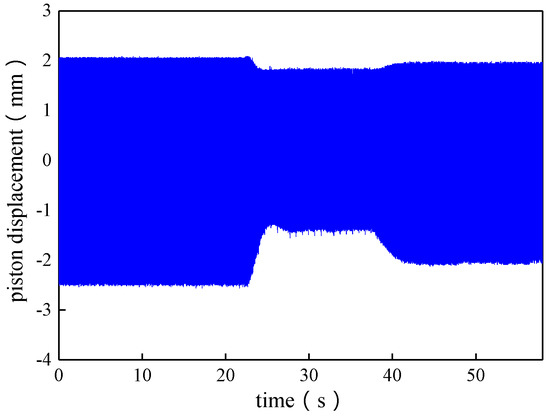
Figure 18.
Piston displacement waveforms with variable load during generating test.
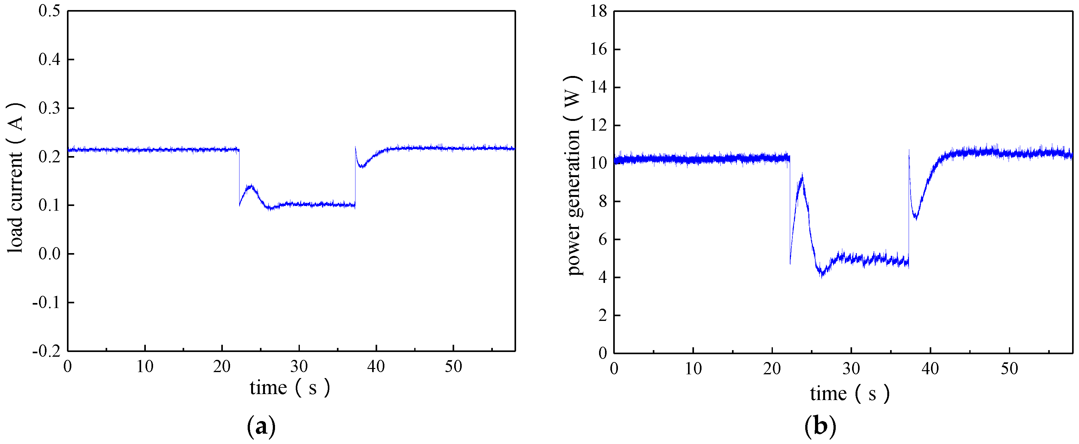
Figure 19 shows the bus voltage waveform with variable load during generating test, and Figure 20a shows the output current waveform with variable load during generating test. As can be seen in the figures, the initial steady-state voltage of the bus is stable at 48 V, and the current is 0.21 A. In 22 s, the load resistance is increased; the bus voltage, which fluctuates greatly, first increases, then decreases, and gradually goes back to the steady state value of 48 V. At this point, the output current is obviously reduced, and the steady-state value of 0.1 A is reached after 3 s of fluctuation. In 38 s, when the load is reduced to the initial value, the system is restored to the initial steady state after about 5 s of adjustment, and the bus voltage and output current values are basically consistent with the initial values.
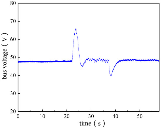
Figure 19.
Bus voltage waveform with variable load during generating test.
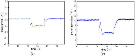
Figure 20.
Output current waveform and power generating waveform with variable load during generating test: (a) output current waveform; and (b) power generating waveform.
Figure 20b shows the power generating waveform with variable load during generating test. The initial power is about 10 W. In 22 s, with the increase of load resistance, the load and the bus voltage are changed at the same time, so the output power fluctuates, and the output power is about 4.3 W. In 38 s, the load is reduced to the initial value.
From the experimental results, when the power generating system is in the process of load mutation, the piston displacement, bus voltage and output current can be quickly adjusted to steady state, and the piston stroke is stable. Moreover, the system has not been flush or stopped, and the ripple of voltage and current is small, which proves that the power generating system has better transient characteristics. It should be noted that the low-power of power generating system is limited by the pressure wave generator, but the generating system still verifies the correctness of the simulation results.
6. Conclusions
To improve the output voltage load response in generating mode, decoupled state feedback is studied for current control, and the influence of full decoupled d-q axis currents is analyzed with respect to the output voltage adjusting time and fluctuation amplitude under the variations of piston displacement and output load. With regard to the dynamic regulation lag in the decoupled current control caused by system parameter variations, an optimized control strategy based on internal model control is proposed, which improves the performance of the decoupled-state feedback current control that relies on system parameter accuracy, and further reduces output voltage ripple in generating mode. Finally, the voltage control performances of the steady state and transient state are tested by experiments. The feasibility and priority of the control strategy is verified by experiment and simulation results.
Author Contributions
All the authors have contributed significantly. Jigui Zheng surveyed the backgrounds of the research and proposed the main idea of IMC-SM control strategy. Jigui Zheng, Jing Chen, Ping Zheng and Hongxing Wu contributed to the modeling and the simulation. Chengde Tong verified the control strategy by experiment. The authors worked collectively on the manuscript preparation.
Conflicts of Interest
The authors declare no conflict of interest.
References
- Oriti, S.; Cornell, P. Processing and Preparation of Advanced Stirling Convertors for Extended Operation at NASA Glenn Research Center. In Proceedings of the 6th International Energy Conversion Engineering Conference (IECEC), Cleveland, OH, USA, 28–30 July 2008; p. 5792. [Google Scholar]
- Geng, S.M.; Mason, L.S.; Dyson, R.W.; Penswick, L.B. Overview of Multi-Kilowatt Free-Piston Stirling Power Conversion Research at Glenn Research Center; NASA/TM–2008–215061; NASA Glenn Research Center: Cleveland, OH, USA, 2008.
- Dunlap, M.A.; Wilson, K.; Skivers, R.; Barnes, O. Sunpower Implementation of Advanced Stirling Convertor Quality Management System. In Proceedings of the 6th International Energy Conversion Engineering Conference (IECEC), Cleveland, OH, USA, 28–30 July 2008; p. 5657. [Google Scholar]
- Ibrahim, T.; Wang, J.; Howe, D.; Nor, M.N. Design and Optimisation of a Moving-Iron Linear Permanent Magnet Generator for Reciprocating Compressors using Finite Element Analysis. Int. J. Electr. Comput. Sci. 2010, 164, 277–288. [Google Scholar]
- Du, Y.; Chau, K.T.; Cheng, M.; Fan, Y.; Zhao, W.; Li, F. A Linear Stator Permanent Magnet Vernier HTS Machine for Wave Energy Conversion. IEEE Trans. Appl. Supercond. 2012, 22. [Google Scholar] [CrossRef]
- Zheng, P.; Zhu, S.H.; Yu, B.; Cheng, L.M.; Fan, Y.H. Analysis and Optimization of a Novel Tubular Staggered-Tooth Transverse-Flux PM Linear Machine. IEEE Trans. Magn. 2015, 51. [Google Scholar] [CrossRef]
- Garber, A.E. Modifications to the Fission Surface Power Primary Test Circuit (FSP-PTC). In Proceedings of the 2008 Space Technology and Applications International Forum, Albuquerque, NM, USA, 10–14 February 2008. [Google Scholar]
- Wood, J.G.; Stanley, J. Free-Piston Stirling Power Conversion Unit for Fission Power System, Phase II Final Report; Technical Report; NASA Glenn Research Center: Cleveland, OH, USA, 1 August 2016.
- Chapman, P.A.; Vitale, N.A.; Walter, T.J. 5-kWe Free-Piston Stirling Engine Convertor. In Proceedings of the Space Technology Applications International Forum (STAIF-2008), Albuquerque, NM, USA, 10–14 February 2008. [Google Scholar]
- Mason, L.S.; Schreiber, J.G. A Historical Review of Brayton and Stirling Power Conversion Technologies for Space Applications. In Proceedings of the Space Nuclear Conference 2007, Boston, MA, USA, 24–28 June 2007. [Google Scholar]
- Tavakolpour-Saleh, A.R.; Jokar, H. Neural network-based control of an intelligent solar Stirling pump. Energy 2016, 94, 508–523. [Google Scholar] [CrossRef]
- Dyson, R.W.; Geng, S.M.; Tew, R.C.; Adelino, M. Towards fully three-dimensional virtual Stirling convertors for multi-physics analysis and optimization. Eng. Appl. Comput. Fluid Mech. 2008, 2, 95–118. [Google Scholar] [CrossRef]
- Tavakolpour-Saleh, A.R.; Zare, S.H.; Bahreman, H. A novel active free piston Stirling engine: Modeling, development, and experiment. Appl. Energy 2017, 199, 400–415. [Google Scholar] [CrossRef]
- Huth, J.; Gomez, A.; Roychoudhury, S. Progress toward a Wearable 35 We Free-Piston Stirling Engine-Based Soldier Power Source. In Proceedings of the 4th International Energy Conversion Engineering Conference and Exhibit (IECEC), San Diego, CA, USA, 26–29 June 2006; p. 4016. [Google Scholar]
- Gerber, S.; Jamison, M.; Regan, T.; Roth, M.E. Advanced Controller for the Free-Piston Stirling Convertor. In Proceedings of the 2nd International Energy Conversion Engineering Conference, Providence, RI, USA, 16–19 August 2004; pp. 1–11. [Google Scholar]
- Němeček, P.; Šindelka, M.; Vysoký, O. Ensuring Steady Operation of Free-Piston Generator. Syst. Cybern. Inf. 2006, 4, 19–23. [Google Scholar]
- Kirby, R.L.; Vitale, N. Update on development of a control system for a 5 kilowatt free piston stirling engine convertor. In Proceedings of the IEEE 6th International Energy Conversion Engineering Conference (IECEC), Cleveland, OH, USA, 28–30 July 2008; pp. 1–9. [Google Scholar]
- Dahoussi, Z. An Inverter-Based Sensorless Controller for Free-Piston Stirling Engines. In Proceedings of the 35th Annul IEEE Power Electronics Specialists Conference, Aachen, Germany, 20–25 June 2004; pp. 1707–1710. [Google Scholar]
- Mikalsen, R.; Roskilly, A.P. The control of a free-piston engine generator. Part 1: Fundamental analyses. Appl. Energy 2010, 87, 1273–1280. [Google Scholar] [CrossRef]
- Zheng, P.; Tong, C.; Bai, J.; Sui, Y.; Shi, W. Electromagnetic design and control strategy of an axially magnetized permanent-magnet linear alternator for free-piston Stirling engines. IEEE Trans. Ind. Appl. 2012, 48, 2230–2239. [Google Scholar] [CrossRef]
- Zheng, P.; Yu, B.; Zhu, S.; Gong, Q.; Liu, J. Research on control strategy of free-piston stirling-engine linear-generator system. In Proceedings of the 2014 17th International Conference on Electrical Machines and Systems (ICEMS), Hangzhou, China, 22–25 October 2014; pp. 2300–2304. [Google Scholar]
- Jia, B.; Smallbone, A.; Zuo, Z.; Feng, H.; Roskilly, A.P. Design and simulation of a two-or four-stroke free-piston engine generator for range extender applications. Energy Convers. Manag 2016, 111, 289–298. [Google Scholar] [CrossRef]
- Redlich, R.W.; Berchowitz, D.M. Linear dynamics of free-piston Stirling engines. Proc. Inst. Mech. Eng. Part A Power Process Eng. 1985, 199, 203–213. [Google Scholar] [CrossRef]
- Regan, T.F.; Lewandowski, E.J.; Schreiber, J.G. Stirling system modeling for linear dynamics analysis. In Proceedings of the Third International Energy Conversion Engineering Conference (IECEC 2005), San Francisco, CA, USA, 15–18 August 2005. [Google Scholar]
- Ulusoy, N. Dynamic Analysis of Free Piston Stirling Engines; Case Western Reserve University: Cleveland, OH, USA, 1994. [Google Scholar]
- Lorenz, R.D.; Lawson, D.B. Performance of feedforward current regulators for field-oriented induction machine controllers. IEEE Trans. Ind. Appl. 1987, 4, 597–602. [Google Scholar] [CrossRef]
- Morimoto, S.; Sanada, M.; Takeda, Y. Wide-speed operation of interior permanent magnet synchronous generators with high-performance current regulator. IEEE Trans. Ind. Appl. 1994, 30, 920–926. [Google Scholar] [CrossRef]
- Yuenan, Z.; Duoshen, F.; Boshi, C. A speed calculation method for induction generator based on voltage decoupling control principle. In Proceedings of the Power Conversion Conference-Nagaoka 1997, Nagaoka, Japan, 6 August 1997; Volume 2, pp. 573–578. [Google Scholar]


© 2017 by the authors. Licensee MDPI, Basel, Switzerland. This article is an open access article distributed under the terms and conditions of the Creative Commons Attribution (CC BY) license (http://creativecommons.org/licenses/by/4.0/).