1. Introduction
With increasing demands for energy optimization and environmental protection, more and more research efforts have been put into pure electric vehicles (EVs) because of their considerable advantages in terms of fuel substitution and zero emissions over traditional vehicles and hybrid electric vehicles (HEVs). However, commercial demands for range extension and cost saving make powertrain system design for EVs a challenging task. Various powertrain solutions for EVs have been studied and developed. Generally, their structures can be classified into two categories: centralized motor-driven and distributed motor-driven [
1,
2,
3]. According to the research [
1,
4], as a novel configuration, distributed motor-driven EVs have advantages in terms of vehicle motion control, energy optimization, and structural flexibility [
4,
5,
6]. However, centralized motor-driven EVs are still mainstream in the current market due to their better inheritance to conventional vehicles. Moreover, compared with internal-combustion engine (ICE), electric motor generally owns much higher efficiency, better starting performances, and a flatter efficiency map. The mechanical clutch and even transmission are no longer necessary in centralized motor-driven EVs [
7,
8]. The centralized motor-driven powertrain with a fixed gear ratio has been adopted widely in most present EVs, which can simplify a powertrain’s structure. However, some study results show that it is difficult to balance efficiency, drivability, and motor size reduction for a centralized motor-driven powertrain with a fixed gear ratio. Multi-speed schemes, e.g., two-speed or three-speed transmissions, can enable EVs to achieve higher drivability and longer driven distance with a more compact motor size [
9,
10,
11,
12,
13,
14]. There have been various studies on integrated motor–transmission (IMT) powertrain systems for EVs [
9,
10,
15,
16,
17,
18,
19,
20,
21,
22,
23,
24]. A clutchless automated manual transmission (clutchless-AMT) is a suitable choice for the IMT powertrain systems of EVs because of its high efficiency and low cost, which has been applied in some EVs [
8,
15,
16,
24,
25,
26,
27,
28]. Therefore, a clutchless AMT-based IMT system is considered in this study.
While benefiting from the IMT systems, the control system’s design for improving the shifting quality is becoming a challenge due to the absence of a clutch. For an AMT-based powertrain solution, the shifting quality is usually determined by torque holes, shifting impact, and shifting time [
15,
22,
28]. A torque hole is directly caused by the interruption of driving torque when transmission gears are disengaged, which can degrade the vehicle’s drivability. Therefore, the shifting time should be as short as possible. Moreover, the shifting impact also should be minimized for driving comfort and the service life of the system in the shifting process, which also requires proper shifting time. To deal with these problems, an active speed synchronization technology has been adopted widely by researchers to obtain rapid and smooth gear shifting for EVs using an IMT powertrain [
8,
26,
29]. Tseng et al. [
15] presented a five-speed clutchless IMT for EVs, and adopted sliding mode control (SMC) to improve the active speed synchronization process. Liu et al. [
17] presented an active gear-shift strategy for a clutchless IMT in a battery electric bus, and adopted speed synchronization to improve the shift quality. Zhu et al. [
26] proposed a robust optimal speed synchronization control scheme based on preview control, integral control, and state-feedback control to improve speed synchronization in a clutchless IMT system. Stewart and Kadirkamanathan [
11] designed a dynamic model reference controller to improve the speed synchronization control for clutchless gear changing in high performance electric vehicles with a permanent magnet ac (PMAC) motor. Walker et al. [
12] employed a control strategy consisting of two proportional-integral-derivative (PID) control loops to improve the synchronization control in the shifting process for a clutchless IMT powertrain. Moreover, a controller area network (CAN) has been widely adopted in EVs because of its advantages in terms of easy wiring, convenient data sharing, and system integrating [
30,
31,
32]. However, on the other hand, a CAN inevitably imposes a bandwidth constraint and medium-resource contention on the control system, which may lead to network congestion and network-induced delays [
33,
34,
35,
36,
37]. According to the research of Caruntu et al. [
7], the influence of CAN-induced delays can lead to the oscillation of a vehicle drivetrain equipped with an integrated engine and transmission powertrain. A Lyapunov-based predictive control method is proposed to deal with the effect of CAN-induced delays. Zhu et al. [
1,
27] point out that the influence of CAN-induced delays can lead to the instability of the speed synchronization control system in the shifting process and the oscillation of the driveline for an EV with an IMT powertrain. A mode-dependent robust control method is proposed to cope with the effect of time-varying CAN-induced delays.
Different strategies on speed synchronization control and different methods for solving the effect of CAN-induced delays on the shifting quality of an IMT powertrain have been presented. However, none of them considers the drivetrain as a networked control system with network congestion. In other words, an IMT system is considered as a time-delay system in isolation, where the effects of a CAN are simplified purely as system delays. Rather, with the development of modern EVs, an integrated chassis control technology has been strongly required and widely used because of its considerable advantages in terms of vehicle performance optimization, conflict avoidance, and efficiency improvement. In an integrated chassis control system, electronic control units (ECUs) in different subsystems, e.g., the AMT, the motor control system, the anti-lock braking systems (ABS), the electric power steering (EPS) system, and so on, usually are directly interlinked via a CAN to work cooperatively. Various command signals and measurement signals are exchanged among them via the shared CAN. Owing to the bandwidth constraint, network congestion can no longer be ignored, which may lead to the system’s deterioration and make system integration difficult due to the communication overload. Therefore, an IMT control system should be considered as a networked control system with both delays and network congestion rather than an isolated time-delay control system at the control system design phase.
The purpose of this study is to improve the speed synchronization control process for an IMT powertrain system over a CAN. Different from previous research, the contributions are as follows: (1) both the bandwidth constraint and network-induced delays caused by a CAN are considered in the speed synchronization control of the IMT powertrain system, a scheduling-based communication scheme is presented, a new CAN-induced delay model is derived for control system design, and an equation on the network’s utilization is introduced for a network congestion analysis; (2) a co-design scheme combining active period scheduling and discrete-time slip mode control (SMC) is proposed to deal with both the network-induced delays and network congestion of a CAN, which can improve speed synchronization control for high shifting quality while reducing the network congestion for the system’s integration.
The remaining sections of this paper are organized as follows. In
Section 2, a dynamics model of an IMT powertrain is introduced, the speed synchronization control principle is explained, a new scheduling-based communication approach is introduced, and a corresponding equation on network-induced delays is derived. Meanwhile, a general equation on network utilization is adopted. In
Section 3, a novel co-designed scheme combining active period scheduling and discrete-time SMC is proposed for improving speed synchronization control based on a Lyapunov criterion. In
Section 4, co-simulations with a high-fidelity CAN model are carried out to show the effectiveness of the proposed scheme. In
Section 5, the proposed scheme is experimentally validated in a real CAN environment by hardware-in-loop (HIL) tests. Finally, conclusions are summarized in
Section 6.
2. Problem Formulation
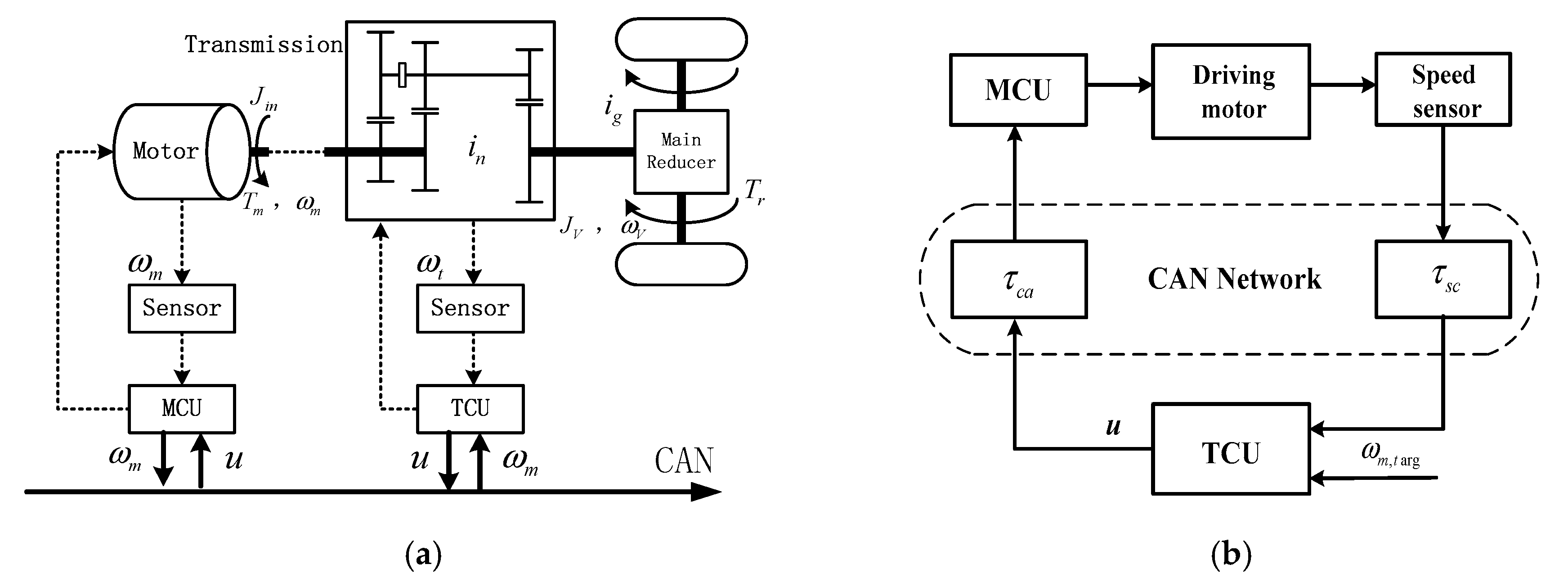
A typical structure of a two-speed clutchless IMT powertrain system using a CAN as the communication medium is shown in
Figure 1, where the motor is directly coupled with a two-speed AMT without clutch for structure simplification. A transmission control unit (TCU) is used to implement the shifting control strategy and a motor control unit (MCU) is employed for motor speed control. They are linked via a CAN. The absence of a clutch greatly influences the shifting quality, e.g., it leads to a severe shifting impact, a long shifting time, and a large torque hole. To deal with these problems, for a clutchless IMT powertrain, an entire shifting process can be divided into six phases [
15]: (1) releasing the motor torque; (2) shifting to neutral position; (3) regulating the motor speed (electronic synchronization); (4) releasing the motor torque again; (5) mechanical synchronization; and (6) restoring the motor torque.
Compared with a conventional shifting process, the motor speed’s regulation (electronic synchronization) is an additional requirement due to the absence of a clutch, whose purpose is to ensure speed synchronization control between the motor and transmission (the speed synchronization control for short). Speed synchronization control is usually implemented by the TCU through actively regulating the motor speed to track the transmission speed. The transmission speed is usually measured by a shaft speed sensor, which is directly linked to the TCU. The motor speed is usually measured by an in-motor speed sensor, which is directly linked to the MCU. The MCU sends a motor speed signal to the TCU by the CAN. The TCU receives the motor speed signal via the CAN, calculates the control command referring to the measured transmission speed, and sends the control command signal to the MCU by the CAN. The MCU receives the control command signal from the CAN and adjusts the motor speed. Therefore, an IMT system is a typical networked control system as shown in
Figure 1b.
2.1. Dynamic Model of IMT Powertrain
As shown in
Figure 1, firstly, when the shifting process is not active, the transmission gears stay engaged. The motor speed is proportional to the output shaft speed. A simplified dynamic model of the powertrain system can be written as follows:
Secondly, in the shifting process, the motor is disengaged from the transmission, and the dynamic equations of the IMT powertrain system can be written as follows:
By comparing Equation (1) with Equation (2), from the perspective of motor speed control, the motor-driving system in the shifting process is characterized by faster dynamics than the one in the process of the transmission gears staying engaged with the vehicle’s inertia as the large load.
In this study, a brushless direct current (BLDC) motor is adopted as the actuator in the clutchless IMT powertrain system, and its simplified dynamics model is expressed as follows:
A recursive least square (RLS) algorithm method is used to identify the parameters
a and
b, which is based on measuring the motor speed and control input voltage. The identification of the parameters is not the key issue of this study. Readers who are interested in the details can refer to [
15].
In addition, with the sampling period of
T, the dynamics model for the motor-driving system can be described as:
In this way, the discrete-time dynamics model of the motor-driving system can be derived as:
where
.
2.2. Speed Synchronization Control Principle
As mentioned above, the purpose of speed synchronization control is to ensure speed synchronization between the motor and transmission. As shown in
Figure 1a, according to the structure of the IMT powertrain and its kinematics, the motor speed
, where
is the driving motor speed,
is the output shaft speed of the transmission, and
is the transmission ratio of the current gear pair. If the transmission ratio of the target gear pair is
, the target motor speed will be
. During the shifting process from the current gear pair to the target gear pair, the speed difference between the current motor speed and the target motor speed can be written as follows:
To guarantee speed synchronization between the motor and transmission via the target gear pair, the speed difference should be regulated to zero. In an upshifting process , the motor speed should be reduced by . In a downshifting process , the motor speed should be increased by .
2.3. Scheduling-Based Network-Induced Delays of the CAN
As shown in
Figure 1b, the set of network-induced delays in the loop consist of the feedback channel delays and the forward channel delays:
where
is the network-induced delays in the forward link from the controller to the actuator, and
is the network-induced delays in the feedback link from the sensor to the controller.
According to previous research [
33], a CAN usually leads to time-varying delays due to its flexible carrier sense multiple access (CSMA) mechanism, which is an event-driven communication scheme. The time-varying delays usually result in uncertainties, which make control system design a challenge. Different from previous research, a new scheduling-based communication approach is presented to deal with the problem in this study. The scheduling-based communication approach is named the “one request, all response” scheme, where a master node periodically broadcasts a request message with the highest priority, while all network nodes including the sensor, controller, and actuator will immediately implement their tasks once they receive the broadcasted request message. It can be described in detail as follows:
- (1)
The TCU is chosen as the master node to periodically broadcast a request message with the highest priority;
- (2)
All network nodes work in an event-driven mode, where tasks are triggered by the broadcasted request messages: the task in the motor speed sensor node is measuring and sending a motor speed signal to the CAN; the task in the TCU node is calculating and sending a command signal to the CAN; and the task in the motor actuator node is executing the control effect.
- (3)
Each task’s implementation time in the sensor and controller nodes and the blocked time suffered by the request message with the highest priority are relatively small enough, which can be ignored.
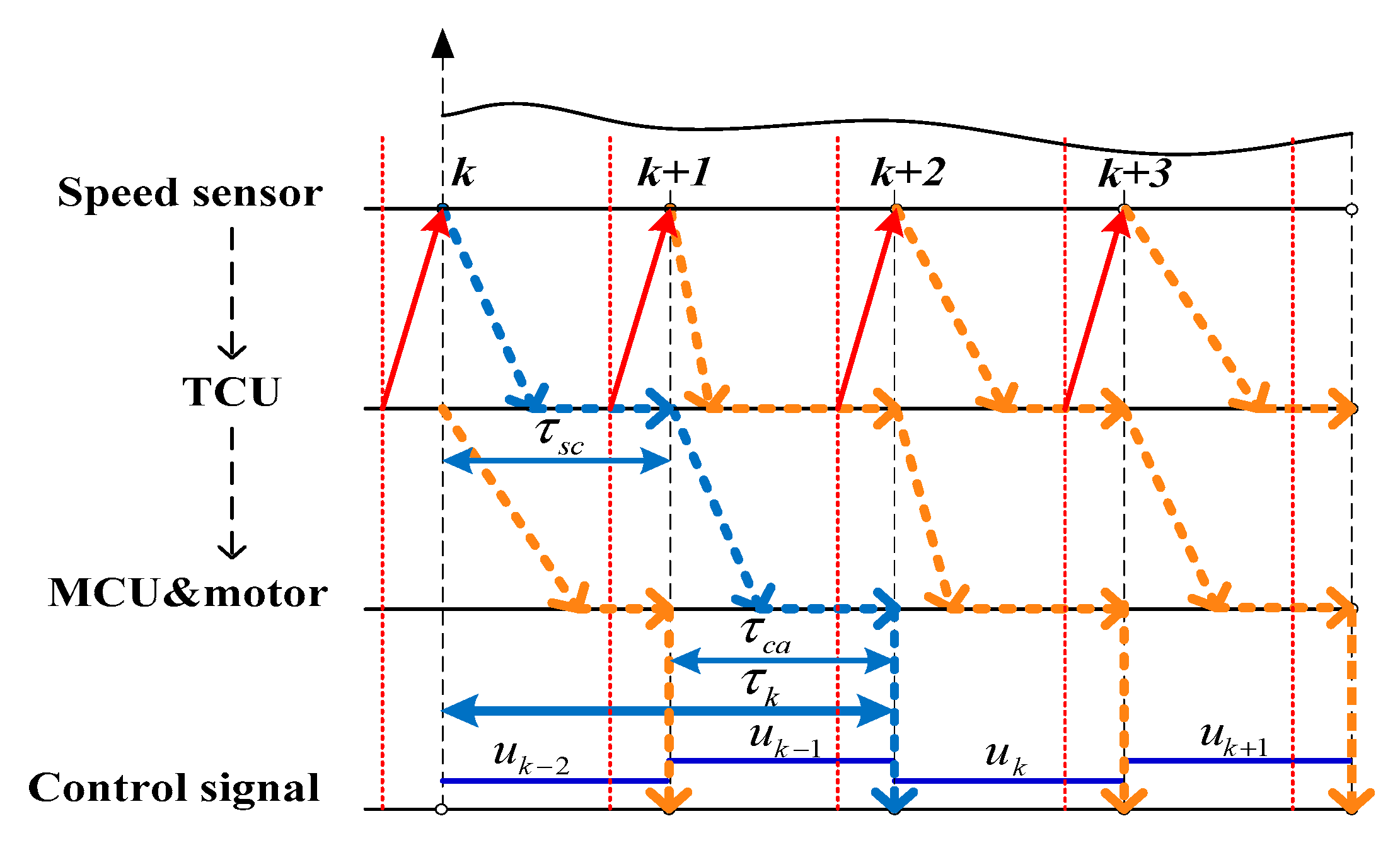
Based on these assumptions, all network nodes, including the sensor node, the controller node, and the actuator node, will actually work in a scheduling-based time-driven mode, as shown in
Figure 2. The proposed scheduling-based communication approach has two advantages: firstly, it can transform varying network-induced delays into constant network-induced delays, which can effectively reduce system uncertainties. It is very beneficial for control system design. Therefore, the network-induced delays in each cycle can be depicted as follows:
Secondly, it makes active period scheduling feasible and practical through managing the broadcasted request messages in the master node, which is very beneficial for dealing with network congestion.
With the constant network-induced delays as in Equation (8), the dynamics model of the motor-driving system subject to the delays can be rewritten as:
Further, the discrete-time dynamics model of the motor-driven system over a CAN is rewritten as follows:
where
.
2.4. Network Utilization Rate of the CAN
For a CAN-based networked control system, with the protocol rules of CAN2.0B, a general equation on the network utilization rate is introduced as follows [
33]:
where
3. The Control System’s Design
The control system’s design is described in detail for networked speed synchronization control in this section. According to Equations (8) and (11), the sampling period plays an important role, which can directly affect network-induced delays and the network utilization rate. In this study, a co-design scheme combining active period scheduling and discrete-time sliding mode control (SMC) is proposed to improve speed synchronization control, which is subject to both network-induced delays and network congestion caused by the CAN.
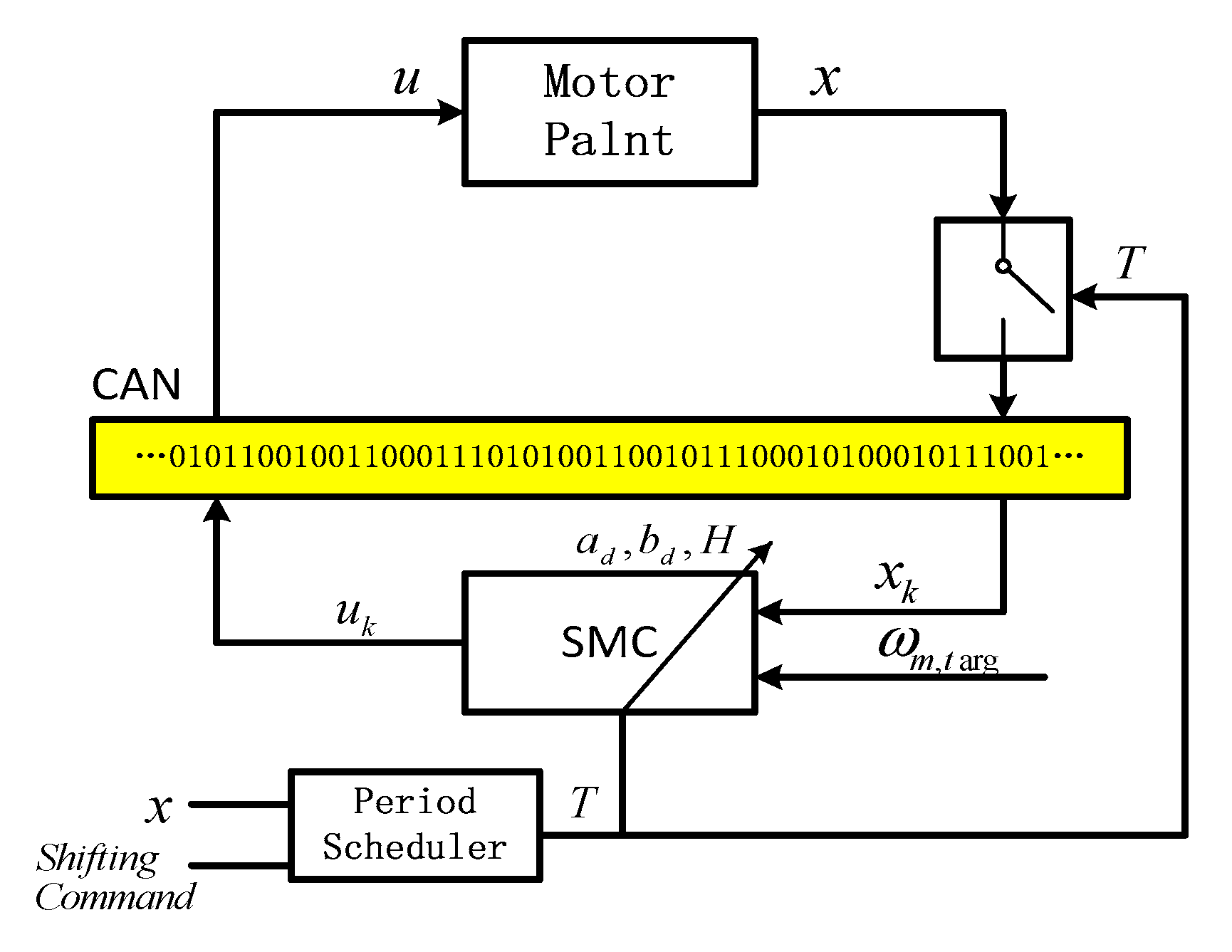
As shown in
Figure 3, in the proposed co-design scheme, the control unit consists of a discrete-time SMC controller and an active period scheduler. The discrete-time SMC controller is used to improve the speed synchronization control’s performance. The active period scheduler is used to actively adjust the system’s sampling period, which aims to deal with the network congestion.
3.1. Design of the Discrete-Time Sliding Mode Controller
Firstly, a discrete-time SMC controller is designed to improve speed synchronization control. The sliding mode surface function is defined as follows:
For a discrete-time system as in (5), to ensure a fast transient response and deal with the chattering problem, a constant-speed reaching law with a boundary layer can be adopted as follows:
where
K is the coefficient of the reaching law,
H is the coefficient of the boundary layer in the reaching law, and
is a saturation function, defined as:
By substituting Equations (5), (13) and (15) into Equation (14), the control law of the SMC controller can be derived as:
In the design of the SMC controller, the reaching speed parameter K can be determined by the expected response time of the speed synchronization control, and the boundary layer parameter H can be determined by the following stability criterion of the closed-loop system.
Substituting the control law of SMC in (16) into the dynamics model (10), the close-loop model is obtained as follows:
By defining an augmented vector
and assuming the reference speed
as constant, the new model set can be described as follows:
where
and
denotes constant terms.
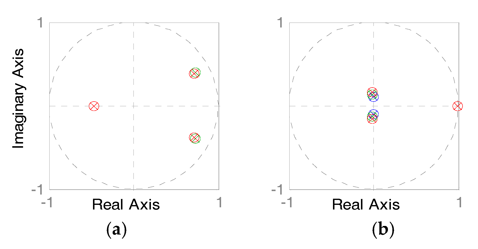
Lemma 1. According to the Lyapunov stability criterion, a system as in (18) is asymptotically stable if all of the eigenvalues of the system’s matrix set are located within the open unit circle on the complex plane as shown in Figure 4. The proper parameters of
K and
H can be found according to Lemma 1. As shown in
Figure 4, if all of the system poles of the closed-loop control system with a known sampling period are located within the unit circle on the complex plane, the system is asymptotically stable.
3.2. Design of the Application-Driven Active Period Scheduler
According to networked control system theory, the sampling period of a typical networked closed-loop system should be designed based on two aspects, as follows:
- (1)
A proper sampling period for the asymptotic stability and a satisfactory transient response of the system; and
- (2)
A proper sampling period for the low network utilization rate to prevent network congestion.
For the control system of the IMT powertrain based on a CAN, as a typical networked closed-loop system, the sampling period is designed in two stages.
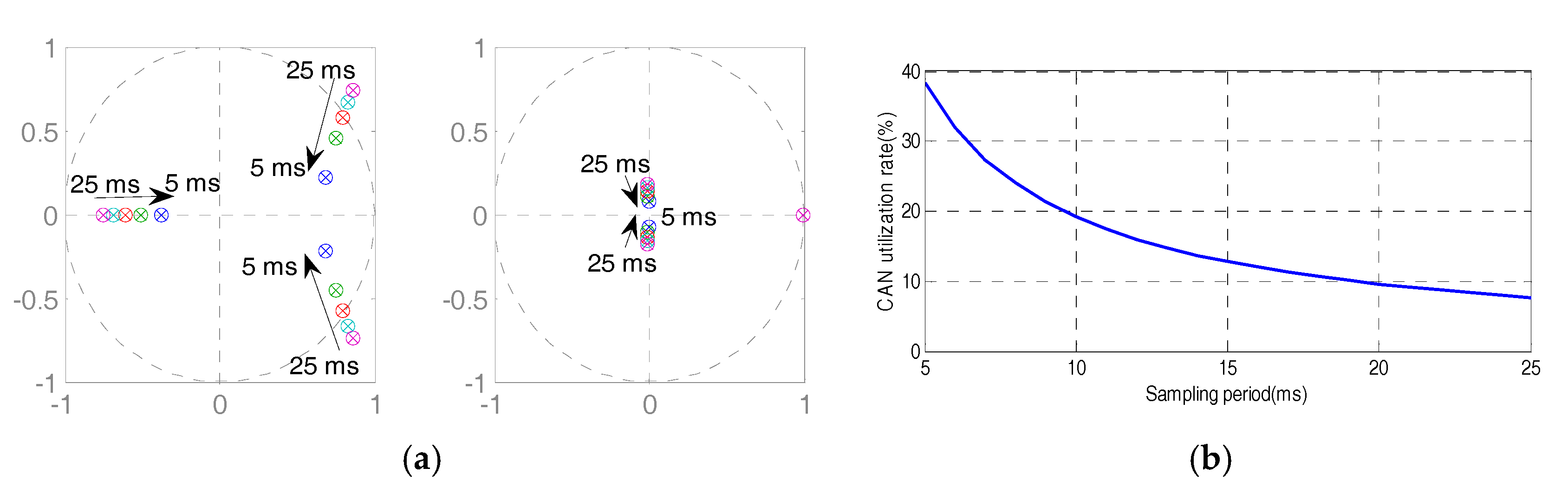
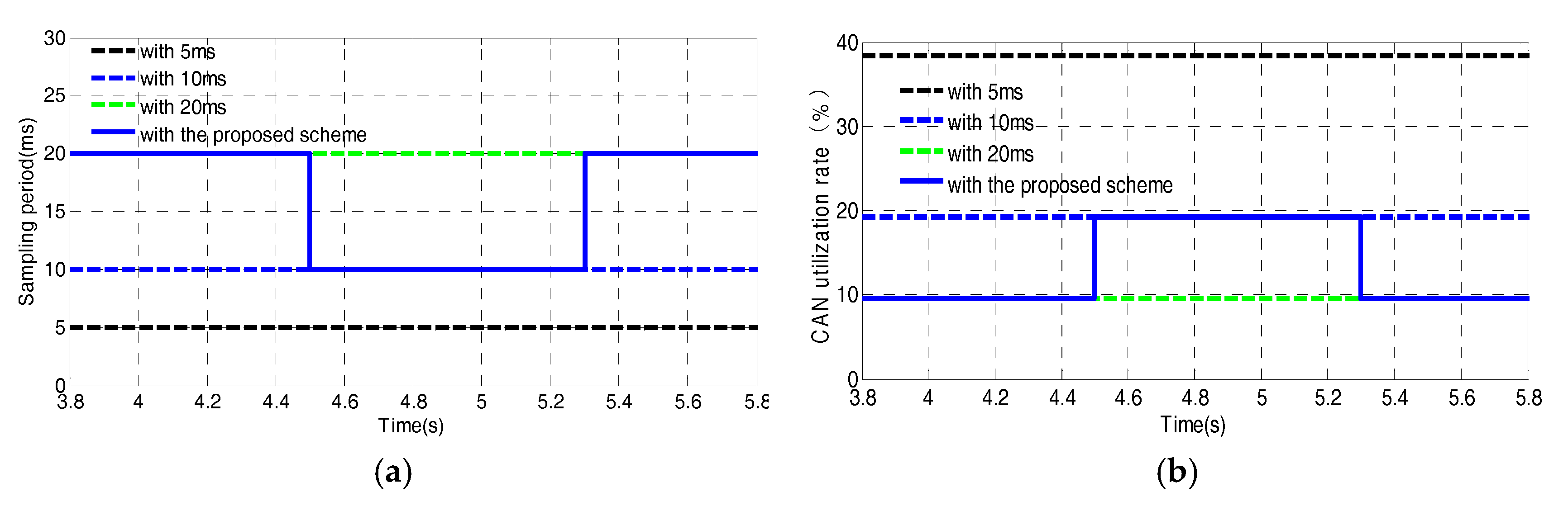
Firstly, for ensuring the asymptotic stability and a satisfactory transient response of the system, with different sampling periods, the closed-loop system with the discrete-time SMC as mentioned above is analyzed through the system pole map as in
Figure 5a. With the increase of the sampling period, the system poles of the system move gradually away from the center. In other words, the smaller the sampling period is, the better the system response is.
Secondly, for the low network utilization rate, with different sampling periods, the CAN utilization rates can be analyzed as in
Figure 5b with Equation (11). The results show that the larger the sampling period is, the lower the CAN utilization rate is.
The design conflict on the sampling period occurs in the networked control system design phase for the IMT powertrain. It is difficult for a control system with a fixed sampling period to satisfy both of the two aspects mentioned above. Therefore, an active period scheduler is proposed to deal with the design conflict.
The active period scheduler is designed based on the rules as follows: if the shifting process is started, the sampling period is chosen as
to satisfy the requirement of system response; if the shifting process is completed, the sampling period is chosen as
to reduce the network utilization rate. The active period scheduler is driven by the shifting flag, the so-called application-driven mode, which can be described as follows:
In this study, according to the above mentioned results, the system response is satisfactory with and the network utilization rate is low enough with .
4. Simulation
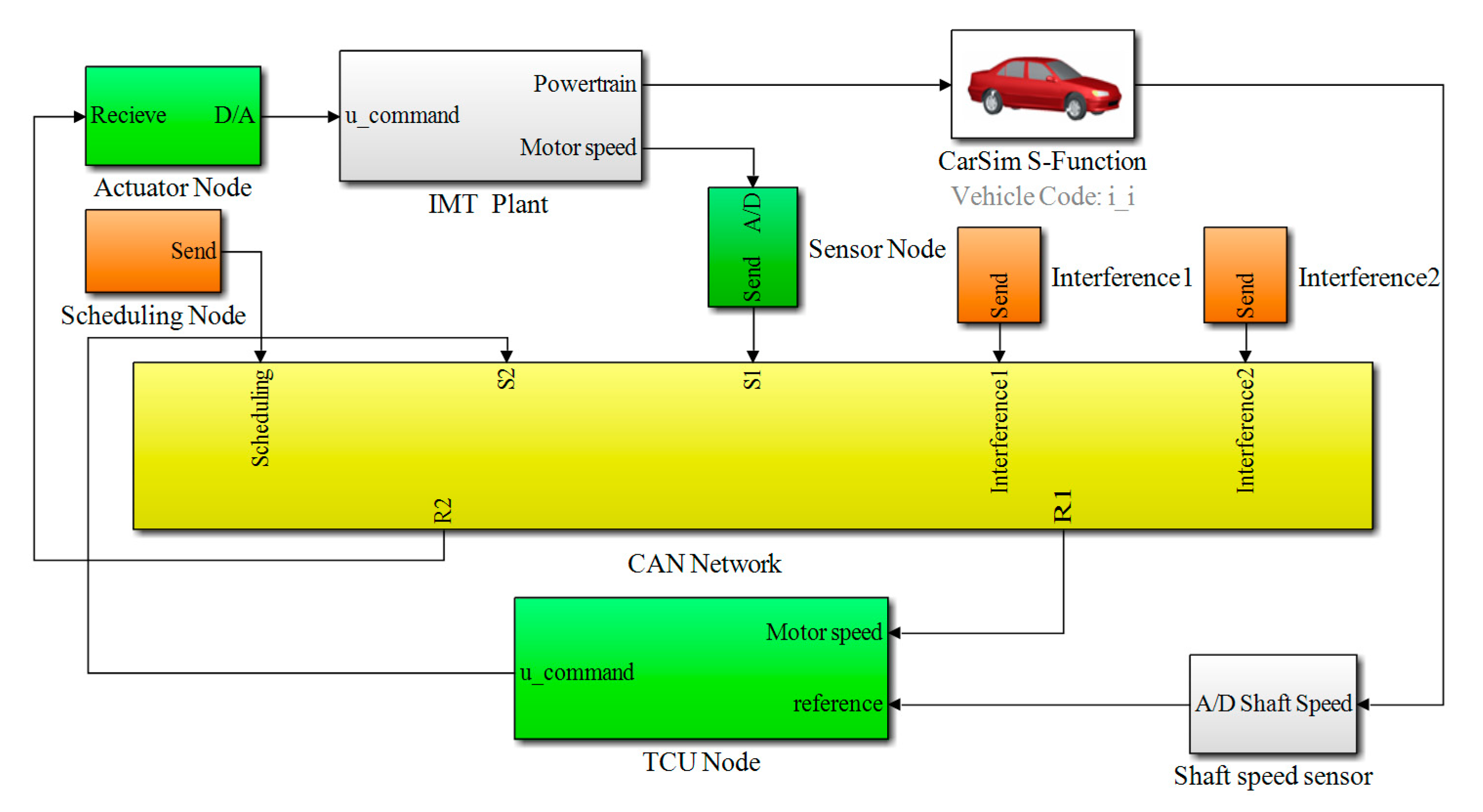
To evaluate the effectiveness of the proposed co-design scheme, co-simulations are carried out in Matlab/Simulink® (R2012b, MathWorks, Natick, MA, USA) with a high-fidelity CAN model from the TrueTime toolbox and a high-fidelity full vehicle model from CarSim® (8.02, Mechanical Simulation Corporation, Ann Arbor, MI, USA) in this section.
Figure 6 shows the co-simulations diagram for evaluating the designed active speed synchronization control system, where the TCU node, actuator node, and IMT plant are designed in the Matlab/Simulink, the CAN network is realized through a TrueTime network block, and the vehicle model is conducted by CarSim.
Table 1 lists the main parameters for the co-simulations, which are based on a prototype powertrain of a two-speed AMT system for EVs. Other parameters of the vehicle are based on a bench model of a C-class hatchback in a CarSim dataset. The media access control (MAC) protocol in the TrueTime network is specified as CSMA/AMP. The baud rate is set as 250 kbps. The length of a data message packet is set as 160 bits (including 3 bits in frame interval), which is the max length of an extended data frame according to CAN 2.0B. Data messages, including a request message, a speed measurement message, a command signal message, and two interference messages, are also defined to implement data exchanging in the CAN-based control system as in
Table 1.
The scheduling-based communication and control process for speed synchronization control is implemented as follows: the TCU node broadcasts the request message via the CAN; all nodes including the sensor node, the TCU node, and the actuator node immediately process tasks once they receive the request message; the sensor node sends the speed measurement signal message to the TCU node via the CAN, the TCU node sends the command signal message to the actuator via the CAN; and the actuator node regulates the motor speed for speed synchronization. The sampling period for the scheduling-based communication and control process can be actively scheduled through adjusting the sending period of the request message. As mentioned above, the active scheduling scheme is designed as:
For a comparative analysis, several schemes with fixed sampling periods of 5 ms, 10 ms, 15 ms, 20 ms, and 25 ms are also designed to be compared with the proposed controller. In the simulations, the speed synchronization error limit is chosen as .
The parameters of the motor-driving system are identified by the RLS algorithm method as:
According to the methods mentioned above, the control gain and the boundary layer in the proposed SMC are designed as:
The results of the co-simulations for speed synchronization control process with different periods are shown in
Figure 7,
Figure 8,
Figure 9 and
Figure 10.
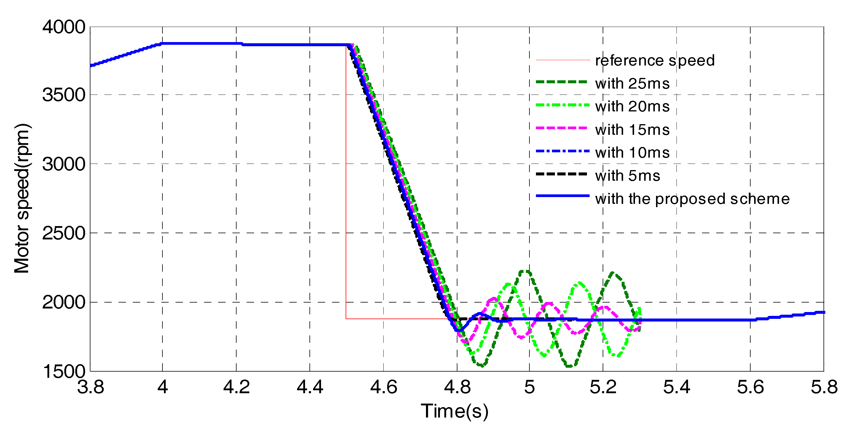
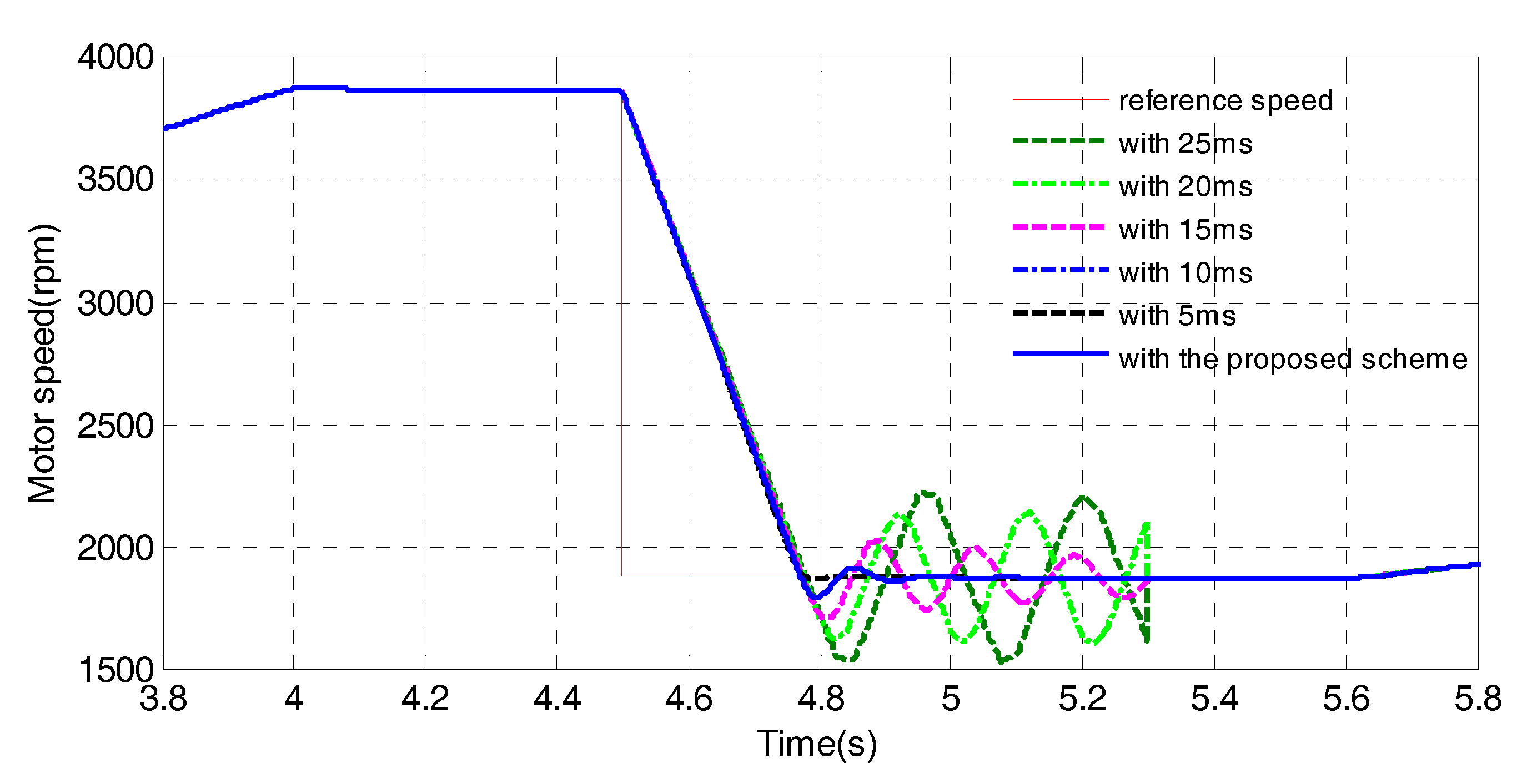
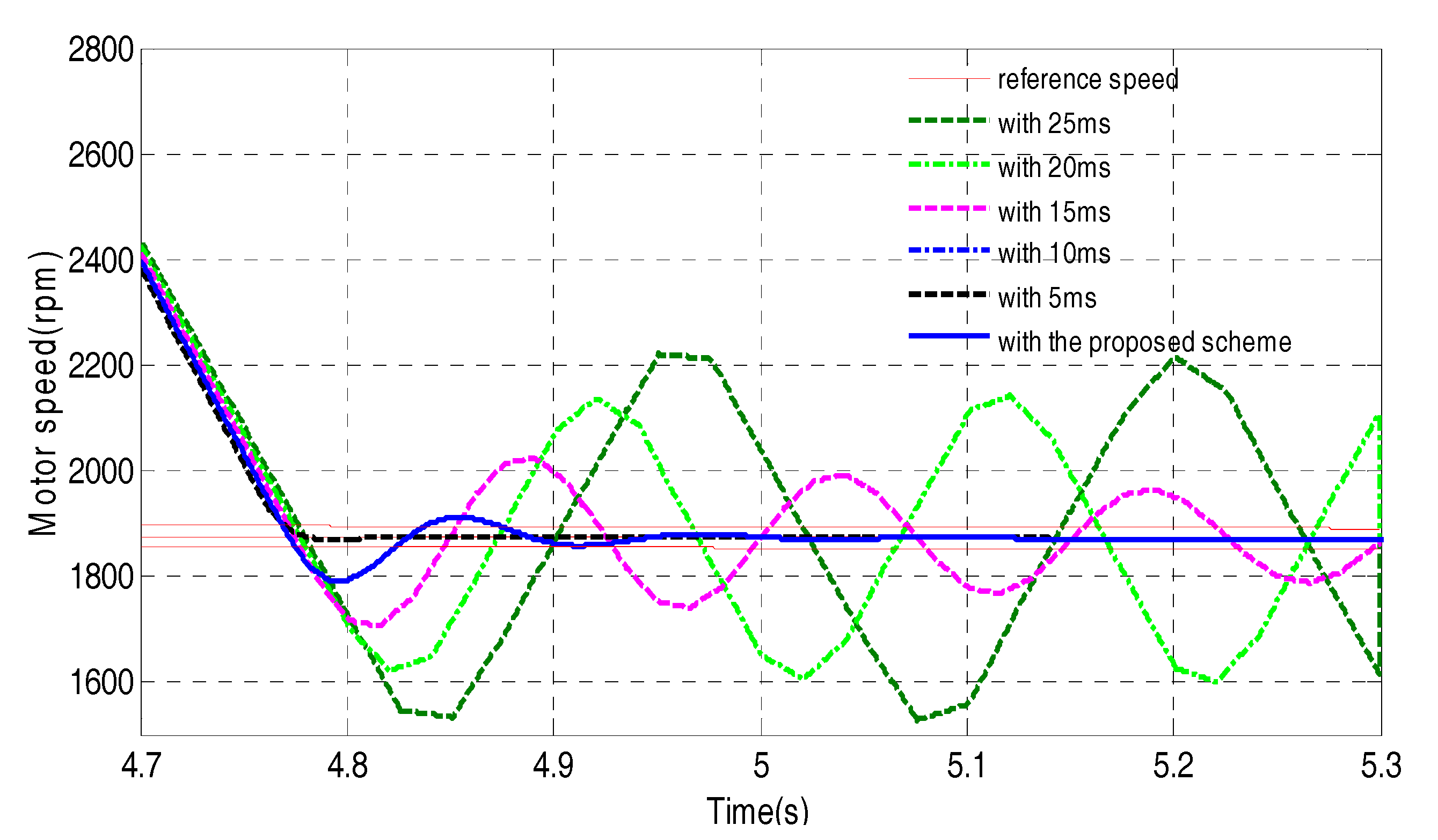
Figure 7 shows the entire upshifting process with different periods, including 5 ms, 10 ms, 15 ms, 20 ms, and 25 ms, and the proposed scheme.
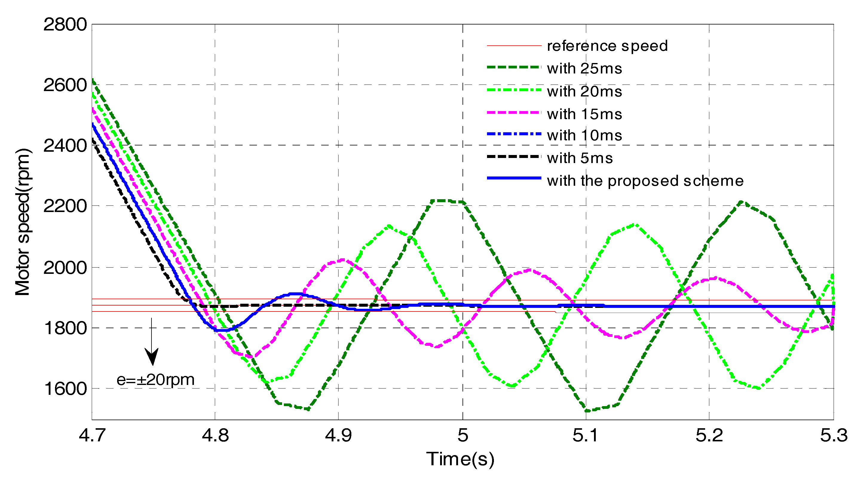
Figure 8 shows the speed synchronization responses with different periods in detail. The results show that, with the larger sampling periods of 25 ms and 20 ms, severe oscillations occur in the speed synchronization control process, which can lead to a shifting impact and even failed shifting. With the sampling period of 15 ms, although this system is asymptotically stable, a too-long transient process is unsatisfactory, which can result in a large torque hole for the vehicles. With the sampling of 10 ms and the proposed scheme, the transient process of around 380 ms is satisfactory, which guarantees a fast and smooth shifting quality. With the sampling period of 5 ms, the transient process of no more than 300 ms is more satisfactory.
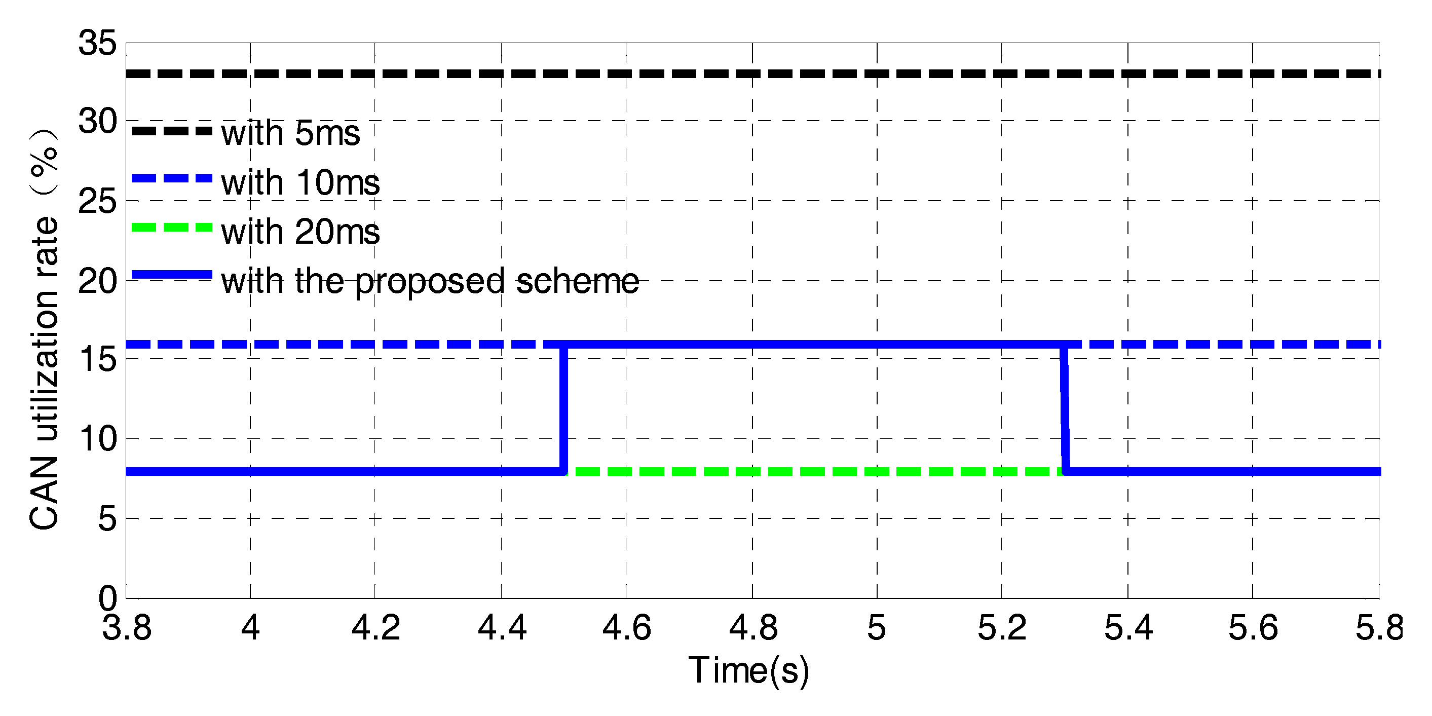
However, on the other hand, as shown in
Figure 9, the sampling period of 5 ms leads to a high utilization rate of around 38%, which may cause severe network congestion in the system’s integration. The sampling period of 10 ms leads to a utilization rate of around 19%, which is still unsatisfactory for preventing network congestion. The sampling period of 20 ms only results in a utilization rate of no more than 10%, which can obviously reduce the network utilization rate compared with 5 ms and 10 ms. The proposed scheme leads to a utilization rate of around 19% only in the shifting process and a utilization rate of no more than 10% when the transmission gears stay engaged.
By combining the two results of the shifting quality and network utilization rate, the proposed scheme not only can ensure satisfactory speed synchronization performance but also significantly reduce the network utilization rate, which is obviously more suitable for a networked control system such as a IMT powertrain using a CAN.
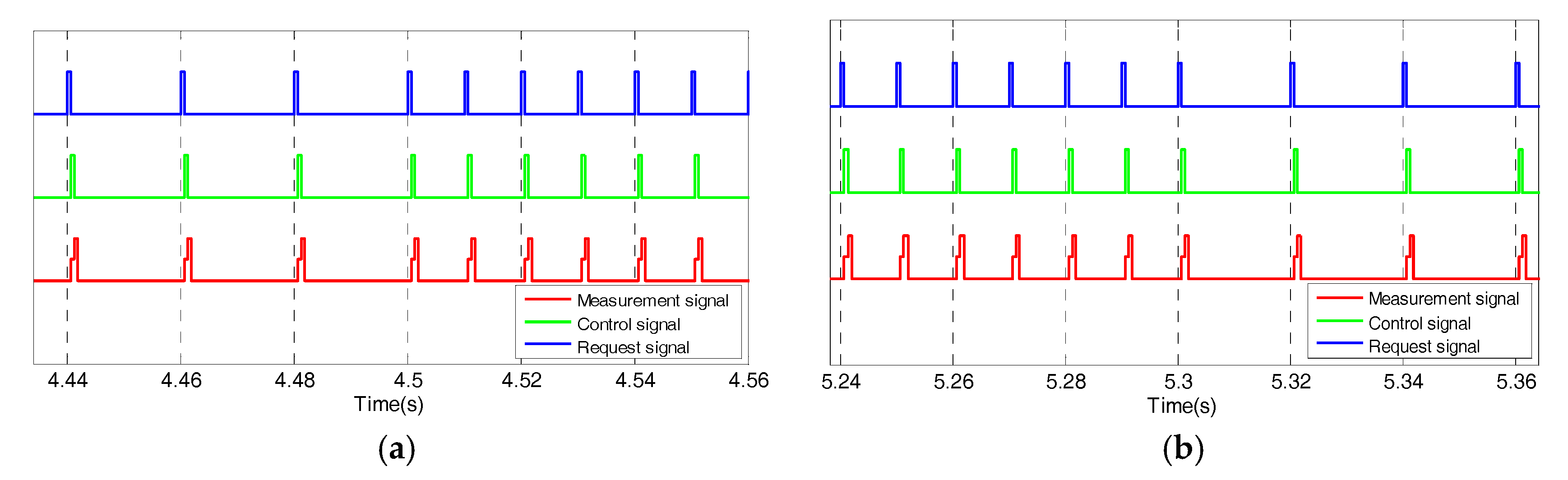
Moreover, with the proposed scheduling-based approach, the communication behaviors of data messages when the shifting is active are shown in
Figure 10a, where the period of the messages in the loop varies from 20 ms to 10 ms. The network-induced delay is also reduced directly in the shifting process according to Equation (8). The communication behaviors of data messages when the shifting is over are shown in
Figure 10b, where the period of the messages in the loop varies from 10 ms to 20 ms. The results also directly show that the network congestion is reduced when the transmission gears stay engaged, which occupies the most of the vehicle’s driving process.
5. Test
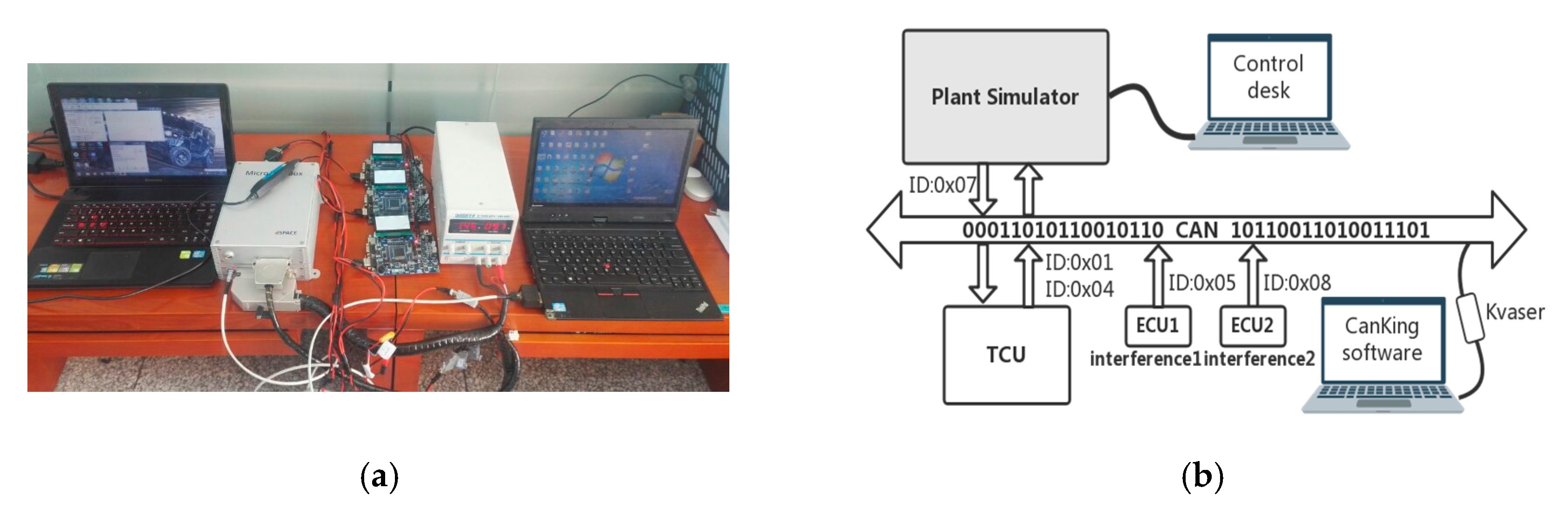
To validate the effectiveness of the proposed scheme in a real CAN environment, as shown in
Figure 11a, a Hardware-In-the-Loop (HIL) test system consisting of a dSPACE MicroAutoBox simulator and three ECUs, based on Freescale 16-bit MC9S12XF512, which are linked by a real CAN is set up. In addition, in order to observe the actual network utilization rate, a computer with Kvaser CANking software as an upper monitor is also linked to the CAN through a Kvaser CAN connector.
In the HIL experiments, as shown in
Figure 11b, the models including the vehicle, IMT powertrain, and actuator node are loaded into the MicroAutoBox simulator, which is a real-time digital system based on a DS1401 board. Moreover, the proposed control strategy is loaded into a real TCU, which is designed based on one ECU with Freescale MC9S12XF512. Two Interference node models are loaded into the other two real ECUs, respectively. In the IMT powertrain simulator, there are two logical CAN nodes: the motor speed sensor node and the motor actuator node. The motor sensor node samples the motor signal and sends it to the TCU via the CAN. The motor actuator node receives the command signal from the TCU via the CAN and executes it. Meanwhile, the TCU receives the motor speed signal, calculates the command signal, and sends it to the actuator node via the CAN. Moreover, two ECUs send interference messages, respectively. The TCU is chosen as a master to periodically send a request message through a timer interrupt function. The parameters of the real networked control system are chosen according to
Table 1 as the same as the ones in the simulations. The messages in the real CAN system are also defined according to
Table 1. In the HIL tests, the messages are in real-time exchanged among the TCU, the IMT powertrain simulator, and two interference ECUs as shown in
Figure 11b.
The test results are shown in
Figure 12,
Figure 13 and
Figure 14. These results show that, with different sampling periods, the speed synchronization control responses and the CAN utilization rates of the loop are similar to the ones in the previous simulations. The HIL test results illustrate that only the proposed scheme can guarantee satisfactory speed synchronization performance while obviously reducing the network utilization rate in a real CAN environment. In contrast, the conventional fixed sampling period schemes are unsatisfactory. Therefore, the proposed scheme is more suitable for the networked IMT powertrain of EVs.
In addition, the network utilization rates in the real CAN are slightly lower than that in the simulation, because the worst-case padding bits in a CAN’s data frames are considered in the simulation with the TrueTime network model.


