1. Introduction
Switched reluctance motor (SRM) is widely used in many fields, such as hauling, aircraft, mining and textile industries, because of its high efficiency, low cost, simple mechanism, great reliability and wide regulating range. Generally, SRM under position closed-loop speed control is equipped with a position sensor to directly measure rotor position signals. However, mechanical sensor not only has raised the system cost and complexity, but also has affected the overall reliability of the SRM drive system [
1]. Therefore, both domestic and foreign researchers have spent considerable time and efforts exploring the SRM rotor position self-sensing technology. However, the nonlinear flux-linkage characteristics of switched reluctance motor make it difficult to detect the rotor position.
A large number of methods for the rotor position self-sensing of switched reluctance motors are studied in recent years. In [
2], a linear frequency modulated converter is used to measure inductance, whose output is decoded to get the rotor angle. But because the detection signal is easily disturbed, this method has low precision. In [
3], a single high-frequency pulse is injected in the non-conducting phase to estimate the rotor angle, which neglects the influence of the back electromotive force (EMF) and the winding equivalent voltage and has estimation precision influenced by speed. In [
4,
5], the observer-based method is used to obtain the rotor angle of full electrical period. However, the observer relies on more complex mathematical models, and the algorithm is complex and difficult to be widely used. In [
6], a look-up table with flux linkage, current and angle is proposed to estimating continuous rotor position, but it has a long look-up time and requires large memory. In [
7,
8], improved simplified flux method with flux-linkage and current at the maximum inductance position is presented, which has less memory and shorter computing time. However, all these methods about look-up table require chopped current control, not fit for angle position control. In all the methods, the flux-linkage is used most in the rotor position self-sensing because it is the fundamental characteristic of SRM. So many studies are focused on obtain accurate flux-linkage characteristic in SRM sensorless control.
In [
9,
10,
11,
12,
13,
14,
15], neural network (NN) and support vector machine (SVM) are used to predict rotor position of SRM, some achievements have been acquired. But the NN prediction process takes up a lot of resources and has long training time, and there are some defects such as local minimum, over fitting. With the increase of training samples, the training time becomes longer with the SVM, and the adaptive ability is poor and the robustness is not strong. Because of the long online decision-making time, the position sensorless SRM based on the NN and SVM methods proposed in the above-mentioned studies works at the maximal rotational speed of 1500 r/min only.
Relevance vector machine (RVM) is a non-linear probability model [
16,
17] put forward by Tipping. Compared to SVM, RVM uses Bayesian methods for reasoning where the kernel function is not necessarily required to fulfill Mercer’s condition—which consequently widen the range of eligible kernel function; more importantly, because the model parameters (relevance vectors) slowly increase as the sample size grows, there are sparser solutions while the model is less complex and the time of decision making is shorter. Thus, RVM is more suitable for the scenarios requiring real-time results. When it is used in rotor position self-sensing, SRM can operate at a higher speed compared to the NN and SVM.
Despite RVM’s advantages, its performance depends on the optimum selection of parameters of kernel function and yet, there are no unified optimum standards [
18]. The commonly methods used mesh parameterization require a large amount of computation and long-time searching; besides, the least square method is largely restricted by the initial iterative value. Hence, it is likely to result in locally optimal solutions. In recent years, the particle swarm optimization (PSO) algorithm [
19] and the genetic algorithm (GA) [
20] have been employed to optimize the parameters of RVM’s kernel function, which have effectively reduced the time of searching and the dependence on the initial iterative value. The PSO algorithm and the GA are both optimization algorithms based on the swarm and adaptation concepts, with the difference between the two lying in that the PSO algorithm enables memorization of optimal particle positions and inter particle information sharing mechanism whereas GA involves complicated genetic operations, such as selection, crossing-over, variation and so on. The former algorithm has the advantage over the latter in convergence, rule setting and implementation. Therefore, in this paper, the PSO algorithm was used for the optimization of RVM parameters.
To fulfill the real-time requirements for rotor position self-sensing, this paper presented an RVM-based SRM rotor position estimation method. From SRM’s non-linear flux-linkage characteristic, an RVM-based rotor position estimation model was built through sampled data training. Considering that the kernel function parameters of the RVM model were difficult to determine, the PSO algorithm was introduced to optimize the parameters of the RVM model to further improve the model’s precision of estimation. It proved that the PSO-RVM model has a higher prediction precision, a shorter on-line testing time than the RVM and SVM model by the simulation. The experiment results show that the motor can operate at 1500 r/min and 3000 r/min steadily in sensorless control.
2. Flux-Linkage Characteristic of SRM
SRM is a brushless stator-rotor double salient pole variable reluctance machine, of which the flux-linkage shows time-dependent unidirectional pulse changes while the air-gap field is of pulsation. The non-linear geometric structure and magnetic circuit make SRM’s single-phase winding flux-linkage
ψ a non-linear function of the phase winding current
i and the rotor position angle
θ:
It can be proved that the equation above has a unique uniform reciprocal function [
9]:
Such that
θ at a time can be calculated according to the known
ψ and
i at the such time. As to a three-phase 12/8 SRM, assumed the stator pole and the rotor pole in an aligned position, i.e.,
θ = 0°, and the stator pole and the rotor slot in an aligned position, i.e.,
θ = 22.5°, according to the symmetry of the SRM structure, the motor’s magnetic characteristic can be reflected by measuring the flux-linkage value of the rotor in the semi-cycle ranging from 0–22.5°, as shown in
Figure 1. It can be seen that: (1) As the excitation current becomes stronger, the rotor position angle decreases, the stator and the rotor gradually align with each other, the magnetic field reaches the state of saturation and the growth of flux-linkage turns increasingly slow in a non-linear manner; (2) There are unique mapping relationships among flux-linkage, phase current and rotor position angle.
3. RVM-Based Regression Modeling with PSO Algorithm
Considering SRM’s non-linear magnetic characteristic, only simplified model of magnetic linkage can be built through regular modeling by mechanism. If the running parameters and status of the SRM system change, the simplified model will bring lower precision, in which case, the precision of using the simplified model for rotor position estimation will decrease accordingly. To prevent model bias and parameter uncertainties that may influence the rotor position estimation model and to improve the precision and self-adaptation of rotor position estimation, in this paper, RVM’s universal approximation of any functions was utilized to identify the SRM rotor position angle.
3.1. RVM Regression Modeling
Given that the input vector set and output vector set of the training samples are
and
respectively, the objective function
is defined to be derived from a model with noise:
where the noise
is subject to the Gaussian distribution with the mean as zero and the variance as
;
represents the weight vector;
expresses the kernel function (not necessarily to satisfy Mercer’s condition). The likelihood function of the training sample set can be described as:
where
;
means the basis function matrix that can be expressed by:
The Gaussian framework was employed to generalize the RVM regression model. The prior distribution of parameters is defined as:
where
is a hyper-parameter.
Based on the prior distribution and plausible reasoning distribution, the posterior distribution of weight can be known through Bayesian inference. The posterior distribution can be expressed by:
where the posterior covariance can be represented by:
The posterior mean can be described as:
where
.The equation of likelihood function (4) of sample set training was used for integration of weight variables and the
and
-dependent marginal distribution of plausible values can be described as:
where
;
represents an n-order unit matrix.
Because the maximum
and
cannot be obtained by Equation (10) with the analytical method, iterative estimation was adopted. Taking a derivative of
based on Equation (10) to make
to zero, the updated value of
can be expressed by:
where
,
is the
ith diagonal element of the posterior weight covariance matrix
R, the calculation result of the known
and
according to Equation (8);
denotes the
ith posterior mean that can be calculated based on Equation (9).
Taking the above-mentioned method to take a derivative of
, the equation can be rewritten as:
Knowing the parameters and , the weighted posterior mean and variance were recalculated. During iteration, most of tend to approach infinity, indicating that the corresponding values equal zero. In this case, the corresponding basis function can be deleted to achieve sparsity. When other values approach infinity in a steady manner, the corresponding is defined as a relevance vector.
In RVM regression modeling, Gaussian kernel function
was applied to the high-dimensional mapping in this study. The RVM regression model can be rewritten as:
where
represents the width of the Gaussian kernel function that reflects the radius of the closed boundary.
3.2. PSO-RVM Model Parameters
The PSO algorithm is an iterative optimization algorithm which is first proposed by Kennedy and Eberhart in 1995. This algorithm is a simulation of social behavior of birds, which is an optimization algorithm based on group (population), similar to GA. Each particle adjusts its evolutionary direction through information interaction with other particles, and avoids falling into local optimum. In addition, PSO algorithm adopts random search strategy different from GA, which is much simpler than GA. Therefore, it shows better performance when solving some optimization problems.
According to Equation (13), when the training samples are determined, the generalization and estimation precision of the RVM regression model depend on the parameter
of the kernel function and yet, there is no unified principle regarding the selection of
[
13]. Therefore, this paper utilized the global searching function of the PSO algorithm to optimize the kernel function parameter
and improve the generalization and estimation performance of RVM.
In a complex m-D space, the PSO algorithm implements searching through loop iteration. In each loop, the velocity and position of particle
i are updated by dynamic tracking of its optimal value
and that of the swarm
. Assumed that
and
are respectively the velocity and position of particle
i,
and
can be updated according to the equations as follows:
where
k means the number of iterations, ω means the inertia weight coefficient,
r(·) expresses a random value between (0, 1) and
c1 and
c2 denote learning factors.
vmax is the predetermined maximum velocity.
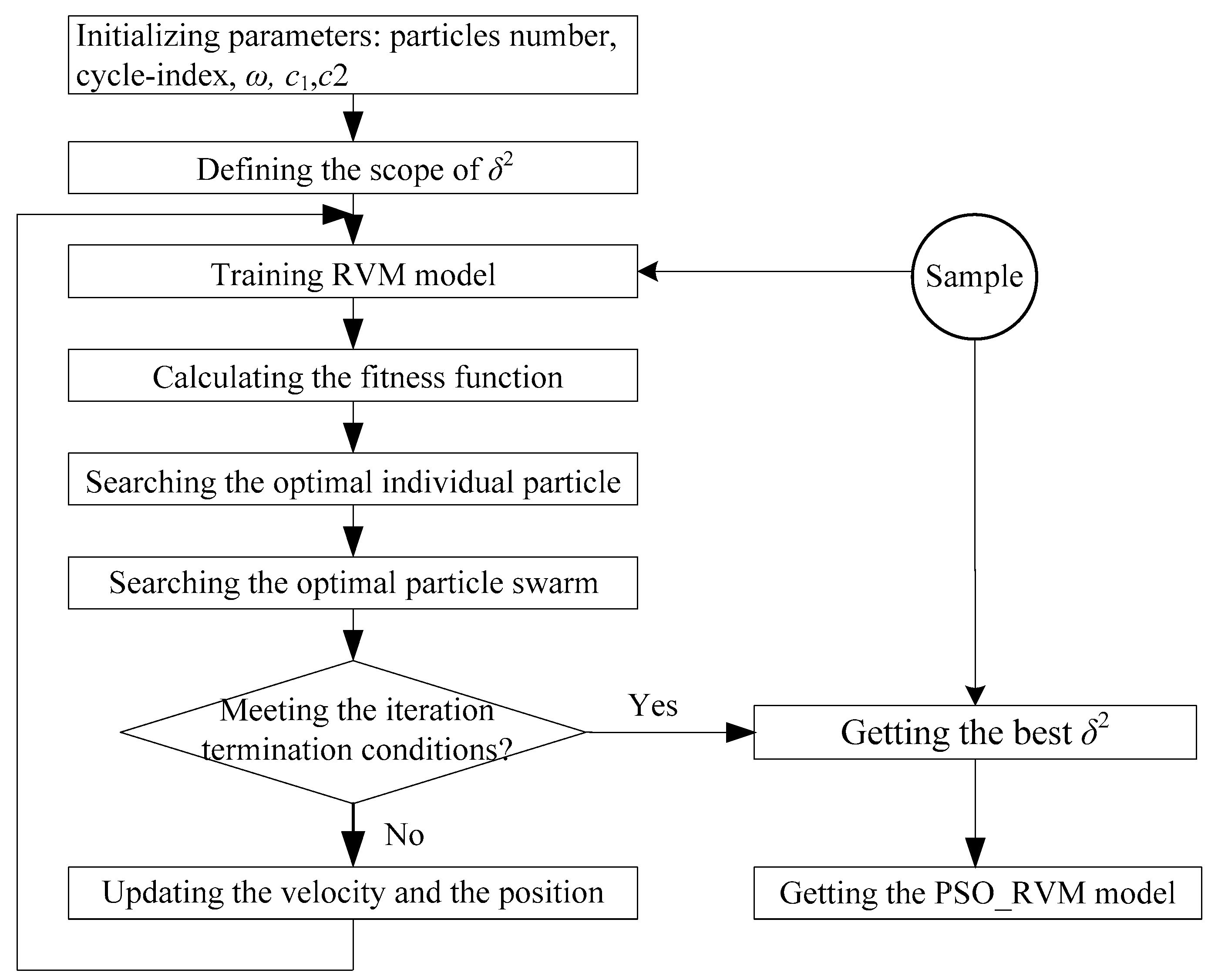
The application of the foregoing PSO algorithm to the optimization of the RVM model parameter
is as shown in
Figure 2.
In the iteration process, the fitness function is defined as:
where
is the predictive value given by the RVM model while
is the actual value.
The suspensive condition of the iterative algorithm is or , where kmax means the maximum number of iteration and fmin represents the minimum adaptive threshold.
4. PSO-RVM-Based SRM Rotor Position Self-Sensoring
According to Equation (2), i and are inputs of PSO-RVM learning while the corresponding is the output. With a limited number of learning samples, the PSO-RVM after learning can reflect the non-linear functional relations and estimate the rotor position.
First, the SRM experiment system was used for sampling to fetch learning samples. Specifically, the phase current and rotor position can be directly detected with sensors while the phase flux-linkage can be indirectly obtained through phase voltage and phase current sampling.
The
jth phase winding voltage loop equation of SRM can be described as:
where
,
and
respectively represent the voltage, current and flux-linkage of the
jth phase and
r denotes the phase winding resistance. Based on Equation (17), the flux-linkage can be expressed by:
where
means the initial flux-linkage value. The flux-linkage in the discrete sampling control system can be described as:
where
and
denote the flux-linkage values of the
kth and the
k − 1th sampling respectively;
,
,
,
are the corresponding voltage, detected current of the
kth and the
k−1th sampling; T represents the sampling time.
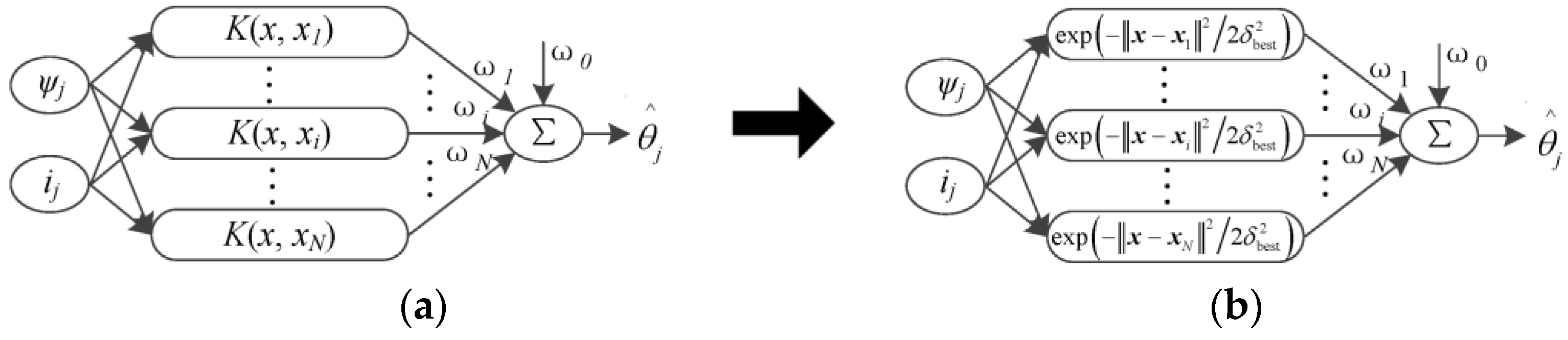
Then, according to the algorithm flow as shown in
Figure 2, the software Matlab was applied to PSO-RVM training in order to obtain the optimal kernel function parameter
δmax best and relevance vector and build a PSO-RVM model for SRM rotor position estimation as shown in
Figure 3, where:
The input variable can be expressed by: .
The Gaussian kernel function after optimizing the kernel width with the PSO algorithm can be described as: .
The output variable can be defined as: .
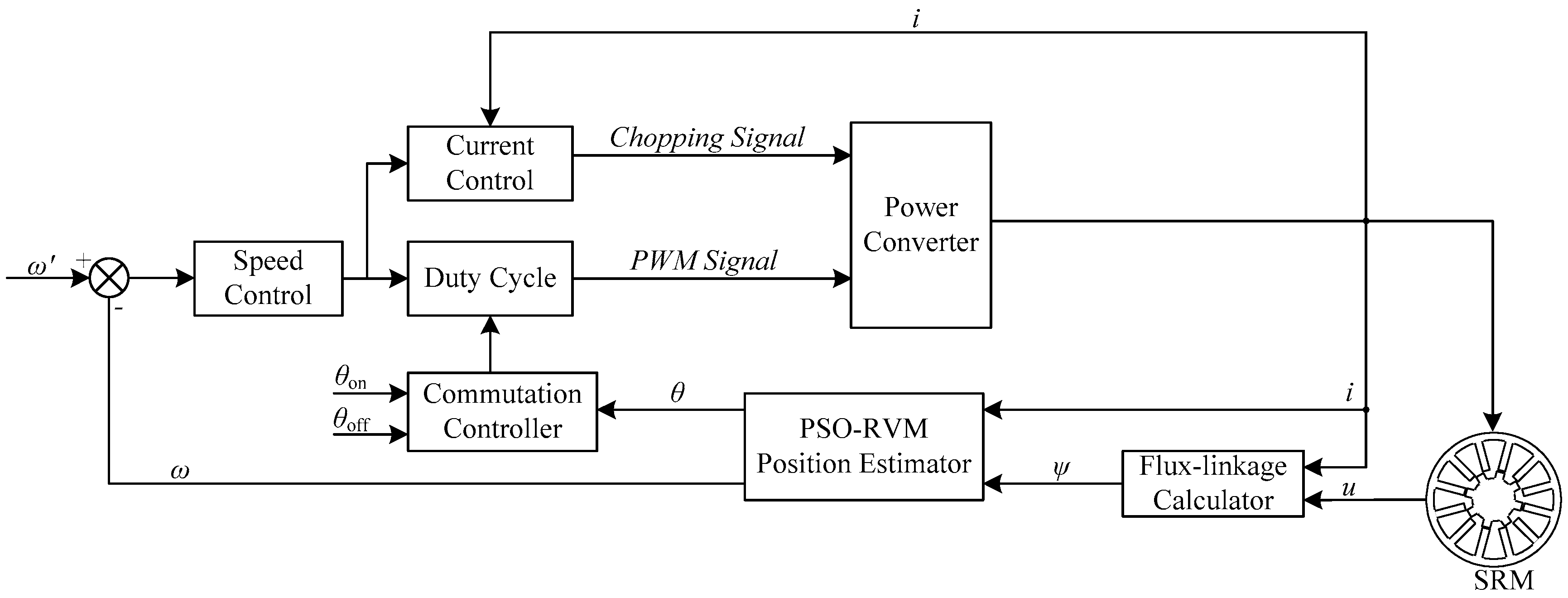
Lastly, the PSO-RVM-based estimation model that was built offline was applied to real-time control. The real-time phase current and phase voltage were detected with sensors while the flux-linkage was calculated according to Equation (20). Subsequently, the current and flux-linkage values were input into the PSO-RVM-based rotor position prediction model to calculate the rotor position at the exact time point and ultimately realize SRM rotor position self-sensoring.


