Adaptive Smart Control Method for Electric Vehicle Wireless Charging System


Abstract
:1. Introduction
2. EV Wireless Charging Control System
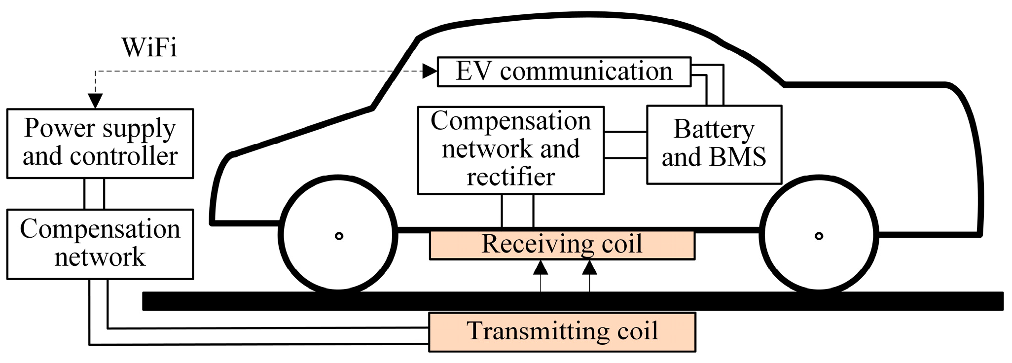
2.1. EV Wireless Charging Control System
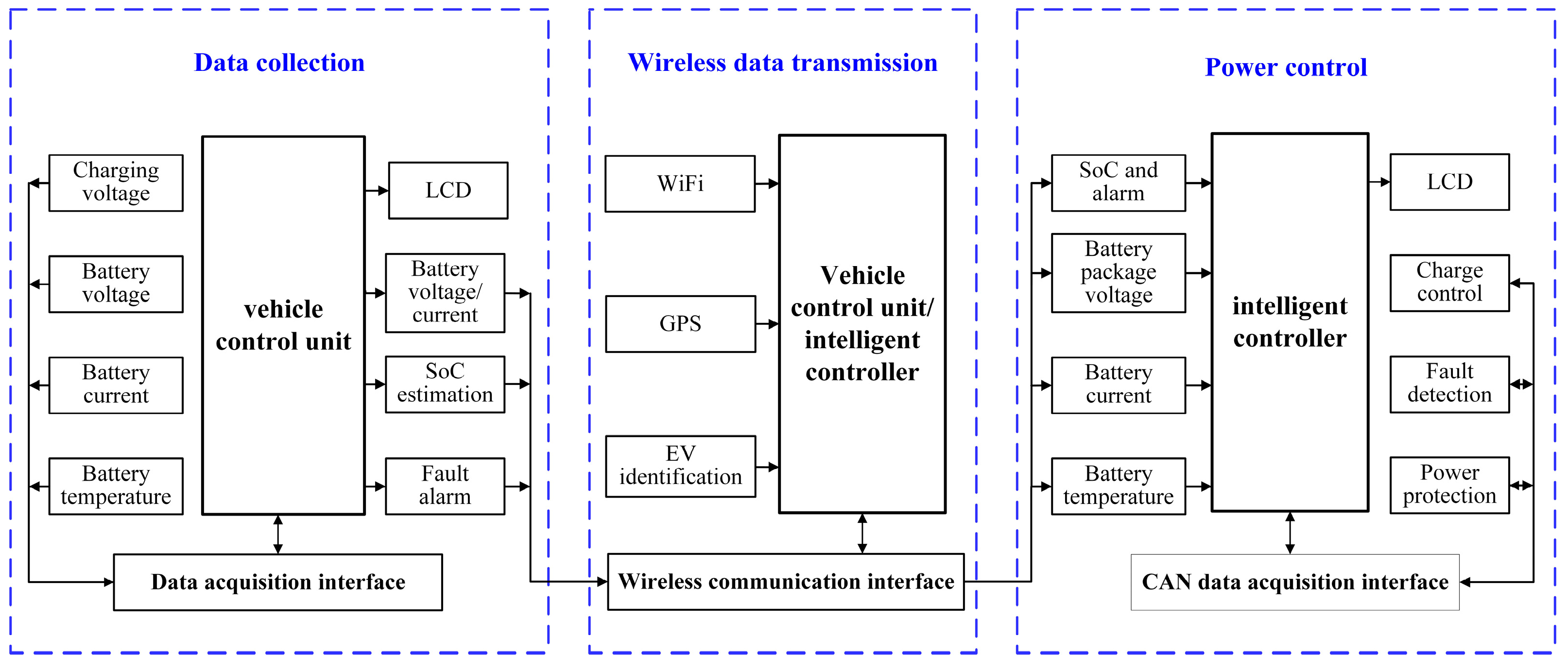
- Data acquisition module. It includes the vehicle terminal, battery, and RS485 communication interface. It has the following functions: (i) collect and record battery state parameters in real time such as the terminal voltage and temperature of the single battery, the charge and discharge current, and the total voltage of the battery pack; (ii) estimate SoC of the power battery pack to keep the SoC value controlled at 30% to 70%; (iii) diagnose fault and alarm. When the battery power or energy is too low to charge or the battery pack temperature is too high, alarm and protect the battery.
- Wireless data transmission module. It includes a WiFi module, a vehicle identification module, and a positioning system. It has the following functions: (i) EV identification. Identify vehicle information and connect to the monitoring system. The EV terminal is embedded with the identification device, and the vehicle identity and battery information can be automatically recognized. (ii) EV position information. This information is obtained by global positioning system (GPS) or other positioning technologies to determine the position and offset of the electromagnetic coupler. (iii) Wireless data transmission. The WiFi module is used to realize the wireless transmission of data, and the information interaction between battery and power.
- Power control module. It includes an intelligent controller, a CAN interface and a high-frequency power supply. It has the following functions: (i) Communication. The CAN bus is used to communicate between the intelligent controller and the power supply. (ii) Data processing, with functions such as power supply over-limit alarm, fault statistics, charging data storage, and power battery data storage. (iii) Control. The intelligent controller adjusts the charging voltage according to the battery information and sends an instruction to the power supply.
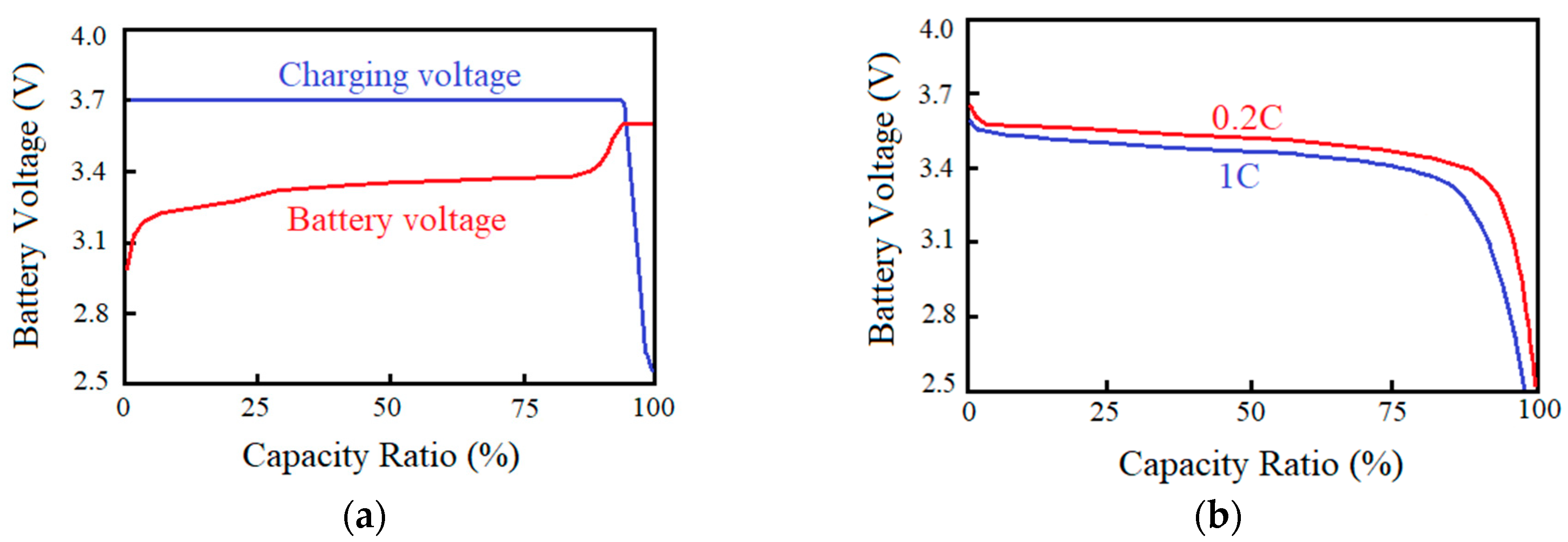
2.2. Rechargeable Battery Characteristics
3. Charging Control Method
3.1. Compensation Network Switching
3.2. Charging Current or Voltage Adjustment
3.3. Charging Control Process
- The power-on phase. After the auxiliary power is turned on, the main power supply will be determined whether it can be powered on. Four power-on conditions must be met: the communication is not timed out, the battery is connected, the power supply is turned on for the first time, and the power supply outputs the charging voltage or current. After the power supply is turned on, the power supply low-voltage auxiliary DC module is powered on, and the rectification control module is started. If the communication does not time out, the real-time and rapidity of the information interaction is ensured. If the battery is connected, it enters a waiting state of charging and completes the communication with the power supply. When powering on for the first time, ensure that full charging is completed at one time. If there is a fault during charging, the whole system is powered off and overhauled. After removing the fault, the charging is re-started.
- The charging control phase. Before the battery voltage reaches the cut-off voltage, the bilateral L3C compensation network is used for CC charge. When the battery voltage reaches the cut-off voltage, the L3C-C compensation network is used for CV charge. Then the charge voltage is set based on the battery voltage. Since the cut-off voltage can be reached rapidly, the CC charging is not segmented. It takes a relatively long time in CV mode, so the voltage segmentation is adopted according to the battery charge characteristic curve. Then the SoC check is performed to determine whether the battery state is normal and the charge voltage is reasonable. If the charge voltage is reasonable, the command is sent to control the power output. The sampling voltage may fluctuate at the critical point, with the result that the output voltage cannot be accurately controlled. Therefore, for a more precise and stable control, the number of samples is set to ensure that the voltage and current value obtained is stable rather than instantaneous.
- The system shutdown phase. System shutdown is divided into normal and abnormal shutdown. If the battery is charged full and the voltage, current, SoC, and temperature are normal (i.e., no alarm information appears), the control system sends the normal shutdown command, the auxiliary power turns off and charging system powers off. Abnormal shutdown includes that voltage, current, or temperature is out of the normal range. Then the system sends the battery alarm information: an overvoltage alarm is generated when the single voltage exceeds 3.75 V and an undervoltage alarm is generated when the voltage is lower than 2.5 V; the upper limit of the temperature alarm is 60 °C and the lower limit is −10 °C Abnormal system shutdown also includes that the SoC estimation is wrong. After the judgement, the power is cut off immediately to protect the charging system.
4. Results and Discussion
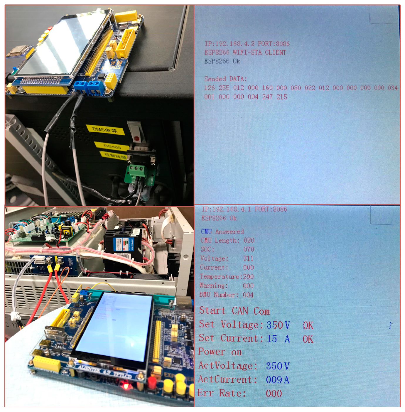
4.1. Charging Control System Platform
4.2. Wireless Data Transmission Experiments
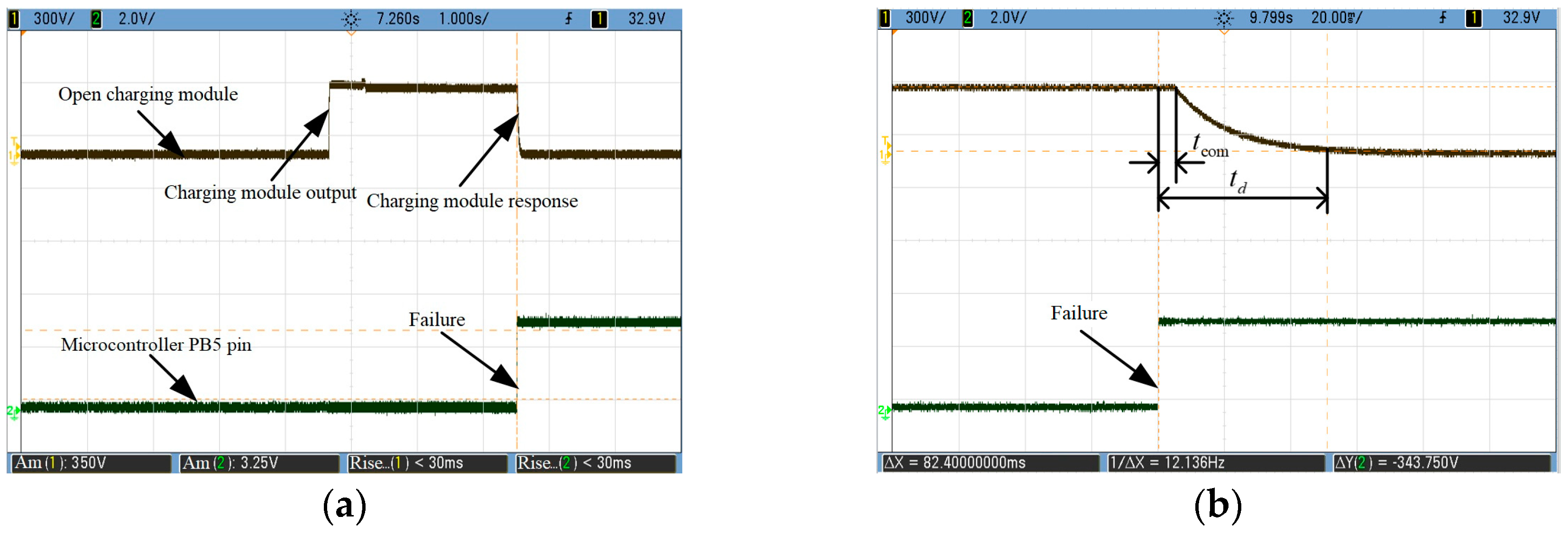
4.3. Adaptive Charge Control Experimental Results
5. Conclusions
Author Contributions
Funding
Conflicts of Interest
References
- Guo, C.; Yang, J.; Yang, L. Planning of electric vehicle charging infrastructure for urban areas with tight land supply. Energies 2018, 11, 2314. [Google Scholar] [CrossRef]
- Aziz, M.; Oda, T.; Mitani, T.; Watanabe, Y.; Kashiwagi, T. Utilization of electric vehicles and their used batteries for peak-load shifting. Energies 2015, 8, 3720–3738. [Google Scholar] [CrossRef]
- Boys, J.T.; Elliott, G.A.J.; Covic, G.A. An appropriate magnetic coupling co-efficient for the design and comparison of ICPT pickups. IEEE Trans. Power Electron. 2007, 22, 333–335. [Google Scholar] [CrossRef]
- Fisher, T.M.; Farley, K.B.; Gao, Y.; Bai, H.; Tse, Z.T.H. Electric vehicle wireless charging technology: A state-of-the-art review of magnetic coupling systems. Wirel. Power Transf. 2014, 1, 87–96. [Google Scholar] [CrossRef]
- Qiang, H.; Huang, X.L.; Tan, L.L.; Huang, H. Study on topology design of wireless power transfer for electric vehicle based on magnetic resonance coupling. Adv. Mater. Res. 2011, 308–310, 1000–1003. [Google Scholar] [CrossRef]
- Khaligh, A.; Li, Z. Battery, ultracapacitor, fuel cell, and hybrid energy storage systems for electric, hybrid electric, fuel cell, and plug-in hybrid electric vehicles: State of the art. IEEE Trans. Veh. Technol. 2010, 59, 2806–2814. [Google Scholar] [CrossRef]
- Bao, K.; Li, S.; Zheng, H. Battery charge and discharge control for energy management in EV and utility integration. In Proceedings of the 2012 IEEE Power and Energy Society General Meeting, San Diego, CA, USA, 22–26 July 2012. [Google Scholar]
- Marinescu, A.; Vintila, A.; Marinescu, D.G. Development of a wireless battery charger for Dacia electron EV. In Proceedings of the 2017 10th International Symposium on Advanced Topics in Electrical Engineering (ATEE), Bucharest, Romania, 23–25 March 2017. [Google Scholar]
- Huang, S.J.; Huang, B.G.; Pai, F.S. Fast charge strategy based on the characterization and evaluation of LiFePO4 batteries. IEEE Trans. Power Electron. 2013, 28, 1555–1562. [Google Scholar] [CrossRef]
- Cabrera, A.T.; Ochoa, M.; Fernandez, D.; Aguado, J.A. Independent primary-side controller applied to wireless chargers for electric vehicles. In Proceedings of the 2014 IEEE International Electric Vehicle Conference (IEVC), Florence, Italy, 17–19 December 2015. [Google Scholar]
- Yuan, Z.; Xu, H.; Han, H. Research of smart charging management system for Electric Vehicles based on wireless communication networks. In Proceedings of the 2012 IEEE 6th International Conference on Information and Automation for Sustainability, Beijing, China, 27–29 September 2012. [Google Scholar]
- Liao, S.H.; Teng, J.H.; Wen, C.K. Developing a smart charger for EVs’ charging impact mitigation. In Proceedings of the 2015 IEEE 2nd International Future Energy Electronics Conference (IFEEC), Taipei, Taiwan, 1–4 November 2015. [Google Scholar]
- Huang, Z.; Wong, S.C.; Chi, K.T. Design of a single-stage inductive-power-transfer converter for efficient EV battery charging. IEEE Trans. Veh. Technol. 2017, 66, 5808–5821. [Google Scholar] [CrossRef]
- Yin, Y.; Gaya, C.; Torayev, A. Impact of Li2O2 particle size on Li-O2 battery charge process: Insights from a multi-scale modeling perspective. J. Phys. Chem. Lett. 2017, 7, 19. [Google Scholar] [CrossRef] [PubMed]
- Panchal, S.; Khasow, R.; Dincer, I. Numerical modeling and experimental investigation of a prismatic battery subjected to water cooling. Numer. Heat Transf. 2017, 71, 626–637. [Google Scholar] [CrossRef]
- Panchal, S.; Mathew, M.; Fraser, R. Electrochemical thermal modeling and experimental measurements of 18650 cylindrical lithium-ion battery during discharge cycle for an EV. Appl. Therm. Eng. 2018, 135, 123–132. [Google Scholar] [CrossRef]
- Hannan, M.A. Lithium-Ion battery charge equalization algorithm for electric vehicle applications. IEEE Trans. Ind. Appl. 2016, 53, 2541–2549. [Google Scholar] [CrossRef]
- Tashakor, N.; Farjah, E.; Ghanbari, T. A bidirectional battery charger with modular integrated charge equalization circuit. IEEE Trans. Power Electron. 2016, 32, 2133–2145. [Google Scholar] [CrossRef]
- Zhai, L.; Cao, Y.; Lin, L.; Zhang, T.; Kavuma, S. Mitigation Conducted Emission Strategy Based on Transfer Function from a DC-Fed Wireless Charging System for Electric Vehicles. Energies 2018, 11, 477. [Google Scholar] [CrossRef]
- Pellitteri, F.; Caruso, M.; Castiglia, V. Experimental Investigation on Magnetic Field Effects of IPT for Electric Bikes. Electr. Power Compon. Syst. 2018, 46, 125–134. [Google Scholar] [CrossRef]
- Kan, T.; Nguyen, T.D.; White, J.C.; Malhan, R.K.; Mi, C.C. A new integration method for an electric vehicle wireless charging system using LCC compensation topology: Analysis and design. IEEE Trans. Power Electron. 2017, 32, 1638–1650. [Google Scholar] [CrossRef]
- Xiao, C.; Cheng, D.; Wei, K. An LCC-C compensated wireless charging system for implantable cardiac pacemakers: Theory, experiment and safety evaluation. IEEE Trans. Power Electron. 2017, 33, 4894–4905. [Google Scholar] [CrossRef]


© 2018 by the authors. Licensee MDPI, Basel, Switzerland. This article is an open access article distributed under the terms and conditions of the Creative Commons Attribution (CC BY) license (http://creativecommons.org/licenses/by/4.0/).
Share and Cite
Gong, L.; Xiao, C.; Cao, B.; Zhou, Y. Adaptive Smart Control Method for Electric Vehicle Wireless Charging System. Energies 2018, 11, 2685. https://doi.org/10.3390/en11102685
Gong L, Xiao C, Cao B, Zhou Y. Adaptive Smart Control Method for Electric Vehicle Wireless Charging System. Energies. 2018; 11(10):2685. https://doi.org/10.3390/en11102685
Chicago/Turabian StyleGong, Lingbing, Chunyan Xiao, Bin Cao, and Yuliang Zhou. 2018. "Adaptive Smart Control Method for Electric Vehicle Wireless Charging System" Energies 11, no. 10: 2685. https://doi.org/10.3390/en11102685
APA StyleGong, L., Xiao, C., Cao, B., & Zhou, Y. (2018). Adaptive Smart Control Method for Electric Vehicle Wireless Charging System. Energies, 11(10), 2685. https://doi.org/10.3390/en11102685