Continuous Hydrothermal Liquefaction of Biomass: A Critical Review


Department of Energy Technology, Aalborg University, Pontoppidanstræde 111, 9220 Aalborg Øst, Denmark
*
Author to whom correspondence should be addressed.
Energies 2018, 11(11), 3165; https://doi.org/10.3390/en11113165
Submission received: 3 October 2018
/
Revised: 10 November 2018
/
Accepted: 12 November 2018
/
Published: 15 November 2018
(This article belongs to the Special Issue Thermochemical Biorefining)
Abstract
:Hydrothermal liquefaction (HTL) of biomass is emerging as an effective technology to efficiently valorize different types of (wet) biomass feedstocks, ranging from lignocellulosics to algae and organic wastes. Significant research into HTL has been conducted in batch systems, which has provided a fundamental understanding of the different process conditions and the behavior of different biomass. The next step towards continuous plants, which are prerequisites for an industrial implementation of the process, has been significantly less explored. In order to facilitate a more focused future development, this review—based on the sources available in the open literature—intends to present the state of the art in the field of continuous HTL as well as to suggest means of interpretation of data from such plants. This contributes to a more holistic understanding of causes and effects, aiding next generation designs as well as pinpointing research focus. Additionally, the documented experiences in upgrading by catalytic hydrotreating are reported. The study reveals some interesting features in terms of energy densification versus the yield of different classes of feedstocks, indicating that some global limitations exist irrespective of processing implementations. Finally, techno-economic considerations, observations and remarks for future studies are presented.
1. Introduction
It is widely accepted that the need for renewable sources of energy is of utmost importance for the sustainable development of our society. The increasing awareness on environmental concerns, such as global warming, has pushed development towards new energy sources, which could, at the same time, be renewable and sustainable. Among the different energy sources, biomass represents a very important part, including into its definition a wide range of materials such as forestry and agricultural residues, energy crops, but also organic wastes such as sewage sludge, food and sorted organic waste can be all considered as biomass [1,2]. Due to its ubiquitous nature, biomass is widely spread all over the world and its distribution is much more even than traditional fossil resources. Aquatic biomass, for example algae, can potentially be grown in any place or in specific reactors, provided the availability of water, sunlight, CO2 and nutrients [3,4]. Biomass can thus be considered the natural substitute for fossil crude oil in the production of liquid fuels and petrochemicals [5].
For many applications, energy is required in liquid forms. Particularly for applications in the field of transportation, for example, this is preferred in order to feed internal combustion engines or turbines [6]. Moreover, the liquefaction of solid biomass is also a way to increase the energy density, since the energy density of raw biomass is in general quite low. This fact directly affects the economic sustainability of a biomass-based process, as it plays a role in the logistics costs. Additionally, once a liquid is produced from biomass, such a liquid can also undergo further processing in order to be converted into drop-in fuels or into valuable chemicals. In order to achieve these positive effects, however, biomass requires proper processing in efficient continuous process systems.
There are essentially two main classes of thermochemical processes able to produce a liquid fuel directly from solid biomass: fast pyrolysis and hydrothermal liquefaction. The former involves a very fast heating of biomass in the absence of oxygen and it is mostly addressed to biomass feedstock with a reduced moisture content (usually lower than 10%), e.g., wood or straw [5,7]. The liquid product resulting from fast pyrolysis generally has a relatively high oxygen content, requiring intensive upgrading for most applications. Indeed, the presence of oxygen in bio-oil determines its instability, especially when heated up to high temperatures. Therefore, these liquids would rapidly polymerize when heated up, which would make their utilization in internal combustion engines quite challenging [8]. On the other hand, hydrothermal liquefaction is potentially able to yield a liquid with a considerably lower oxygen content and to work also with wet biomass, showing great flexibility in terms of feedstock [9,10].
1.1. Hydrothermal Liquefaction Basics
Hydrothermal liquefaction (HTL) involves the reaction of biomass or organic material in the presence of water at hydrothermal conditions, effectively in the range of temperatures from 250 °C to 450 °C, and pressures from approximately 100–350 bar. At these conditions, water remains in a liquid or relatively dense supercritical state. Due to the requirement of a wet reaction environment, HTL is especially suited to wet feedstocks as the need for drying is alleviated. During HTL processing, organic material undergoes a number of depolymerization reactions including hydrolysis, dehydration and decarboxylation to form water-soluble intermediates, and repolymerization reactions including various condensation mechanisms to form water insoluble products including biocrude and biochar. Other products are gases, typically dominated by CO2 but, depending on biomass and reaction conditions, with varying contents of H2, CH4 and CO, as well as an aqueous phase with soluble organics, mostly in the form of alcohols, acids and phenols (for lignocellulosics).
Different types of biomass will undergo different reaction patterns and respond differently to process conditions such as heating rate, temperature, pressure and pH. This review will not go into details of reaction mechanisms, as several original works have presented reaction schemes for lignocellulosic and other organic substrates, e.g., [11,12,13,14,15,16,17,18], the effect of pH modifiers (often referred to as catalysts) (e.g., [19,20], but very often included in HTL studies), temperature and heating rate studies [21,22,23]. A multitude of reviews are available for overviews, e.g., [9,10,23,24]. Most of these, however, are based on studies in batch systems, but still elucidate the fundamental processes.
One aspect of HTL, however, which has consistently been overlooked in the HTL literature—batch as well as continuous—is the effect of pressure at supercritical conditions. Commonly, the accepted temperature and pressure intervals for HTL is much narrower than the one given above, typically stated as maximum 350 °C and pressures up to 200 bar. At these conditions, the properties of water have changed sufficiently to facilitate liquefaction: the dielectric constant has dropped by about 80% to allow for improved solubility of non-polar compounds, but the ionic product is still high enough (above ~10−14 [25]) to favor ionic reactions resulting in oil products rather than radical reactions resulting in solids (coke) or gases. This is shown in Figure 1.
Temperatures above the critical temperature are typically referred to as the hydrothermal gasification regime, due to the steep drop in ionic product by several orders of magnitude around the critical temperature and pressure favoring radical reactions (Figure 1). However, this reasoning has been based on a lack of emphasis on the role of pressure in hydrothermal systems, evident by the absence of reported pressures or simply stating autogenic pressure in several batch studies. This is reasonable at subcritical conditions where temperature is the dominant parameter, but becomes significantly less so at near- and supercritical conditions. Although previously reported in the context of catalytic gasification [26], the effect of pressure at these temperatures has only been explored in the context of HTL in recent years [25,27,28]. As also seen in Figure 1, elevated pressures significantly impact water properties such that conditions favoring liquefaction rather than gasification can be reconstructed at supercritical conditions. For example, at 400 °C and 350 bar, the ionic product is almost the same as at 350 °C, 250 bar, which are “favored” conditions in the literature, but the elevated temperatures drive reactions and their kinetics to achieve more complete deoxygenation. Due to changes in specific heat capacity as well as low compressibility of liquids, the energy cost of going to supercritical conditions is not prohibitive. This is probably one of the most significant single developments within HTL in the last decade.
1.2. Why Continuous?
Batch activities in the field of HTL are common in the literature, due to their relative simplicity of operation [9]. Batch approach consists of loading a mixture of water and biomass into an autoclave, possibly with the addition of a catalyst. The autoclave is then heated up to the desired temperature and, after the selected reaction time, the system is cooled down and the products collected and analyzed. Virtually any type of material can be screened in an autoclave and a wide range of operating conditions and process variations can be tested [18,19,22,32]. A considerable advantage is that relatively high dry matter concentrations can be achieved, without prejudice for the process. A charge with considerable dry matter concentration, i.e., of 20% or 30%, can be easily processed, as there are no complications due to plugging occurring in the pipes or difficulties in pressurizing and pumping the feedstock.
On the other hand, batch testing has several drawbacks, some of which are listed below:
- Thermal transience. During batch operations, process conditions are not constant, because the system has to go from ambient conditions to the desired temperature and hence pressure and back. This transience makes it difficult to separate effects of temperature and time, which is sometimes overcome by using the severity index of Overend and Chornet [33], lumping these two into a single parameter. It is evident that, the faster this heating is, the more the effect of thermal transience can be neglected. This can actually be achieved when the experimental device has a reduced size [34].
- Difficulty in decoupling temperature and pressure. In most batch experiments, pressure is obtained by the heating up of the reactants. As a result, the experimental conditions are often those corresponding to saturation conditions of water, i.e., the points lying on the saturation line in the phase diagram. Pre-pressurizing the system with an inert gas can partially overcome this problem. However, high pressure increases the solubility of the inert gas in liquid water, thus making pre-pressurization less and less useful. In a continuous system, pressure and temperature can be controlled in a completely independent fashion.
- Different contact pattern. In a batch reactor, the reactants are usually completely mixed by means of an impeller or by shaking the reactor itself. This contact pattern could be substantially different from that achieved in a continuous reactor. For example, in a continuous stirred flow reactor (CSTR), although there is continuous mixing, new fresh reactant is continuously supplied and products are continuously removed. In a continuous tubular reactor, flow pattern (laminar or turbulent) can significantly change the outcomes of the process.
- Significant distance towards actual industrial implementation. The industrial utilization of batch type reactors is normally justified only for the production of high added-value products, often produced in limited amounts. This is definitely not the case for fuel production, which often accounts for production volumes in the order of thousands of barrels per day. Additionally, HTL requires a thorough optimization in order to reduce the energy consumption of the process, which can be effectively realized only in a continuous configuration.
It is, therefore, evident that batch processing alone is not able to give results that can be directly utilized for the industrial development of the process. Moreover, testing in continuous devices allows experiencing some technical issues and facts that are typical of continuous processing [35]. One of these is, for example, high pressure pumping, which will be more specifically discussed in the following part of this paper.
1.3. Scope of This Review
In this paper, documented reports of continuous HTL are reviewed, limited to those applications in which the aim is the production of a liquid fuel from biomass or organic material. Typical conditions for an HTL process considered in this treatise involve temperatures no lower than 300 °C and pressures high enough to keep water in a liquid or supercritical state.
The aim of the review is to present the evolution of the activities in the field and the different options available in the open literature, demonstrating the current state-of-the-art. Attention will be given to the description of the different solutions that have been developed to the most common technical issues in the field, such as high-pressure pumping, pressure reduction of the products and optimization of heat exchange. Furthermore, the results of literature studies will be also compared in terms of yield and energy efficiency, by adopting a graphical methodology (Section 3). Aspects concerning the upgrading and valorization of the biocrude and water-phase will be also discussed.
2. Continuous HTL Systems at a Glance
In recent years, several different studies have been proposed in the literature concerning continuous HTL [35]. These plants cover many different sizes: from very small, laboratory-scale plants to larger installations for demonstration on an industrial scale. In Table 1, the continuous HTL plants reported in the literature are listed, along with the typical operating conditions of each one. In Figure 2, the reaction conditions in terms of pressure and temperature are reported on the state diagram of water. It can be appreciated that the different continuous processes cover quite a wide range of conditions, normally in the liquid water region. The selected operating conditions normally fall close to the saturation line of water, and sub-critical conditions are preferred. In general, the selected operating conditions do not deviate significantly from the saturation line. However, in some studies, pressures even significantly higher than saturation pressures are adopted. Although most HTL processes work at subcritical conditions, a few of them operate at or have tested supercritical conditions, even up to 450 °C and 350 bar.
In this section, the state of the art in continuous HTL processing is reviewed from a historical, research and commercialization perspective.
2.1. Historic Processes
The development of processes for the liquefaction of solid biomass follows the needs for oil. A strong driving force in the field was represented by the oil crisis in the 1970s, where the price of oil increased and thus new solutions for non-conventional energy sources were researched. The correlation between high oil prices and bioenergy research has been a constant throughout the years, as it is shown in Figure 3.
In the field of biomass liquefaction at high pressure for the production of bio-crude, the first documented experiences are those conducted in the facility at the Pittsburgh Energy Research Center (PERC) of the U.S. Bureau of Mines. During the late 1960s, the group of Appell at PERC developed a process for the liquefaction of cellulosic biomass [80] and waste biomass [81] in order to produce a liquid with fuel characteristics. The experimental activities were the basis for a further development that took place in a process development unit (PDU) in Albany, Oregon. This facility was designed in 1973 and operations started in 1976. The process operated in PERC involved the liquefaction of biomass at temperatures up to 371 °C and pressure up to 275 bar, in the presence of Na2CO3 and CO. Biomass, in the form of wood flour, was fed to the system as a slurry, obtained by mixing with the oil from the process, which is recirculated back to the pump.
It can be seen that this process is essentially an adaptation to biomass of the Bergius process, which was developed in the 1930s for the liquefaction of coal [82]. The Bergius process involved high temperatures and pressures, although in the presence of hydrogen. The issue of processing solids at high pressure was solved by mixing grinded coal with part of the heavy oil product from the process itself, so that a slurry could be made. Moreover, the Bergius process featured the addition of carbon monoxide in order to increase the yields and quality of the products. All these solutions were also adopted during the development at the PERC facility [83].
During the process development activities, another significant different configuration was tested. The initial process configuration based on oil recirculation turned out to require very high recycling ratios (even up to 1:19). This eventually led to ash accumulation and was not sustainable for the process. An alternative was proposed, involving prior liquefaction of biomass in water, by using acid hydrolysis at 180 °C. This modification was developed by Lawrence Berkeley Laboratories (LBL) and hence involved water as the slurry vehicle [37]. Before feeding, Na2CO3 was added to the slurry in order to set its pH to basic values. This modified process was also successfully tested in the PDU in Albany, as from the late 1970s [84]. A detailed description of the operations carried out in this facility and the different stages of process development can be found in [36]. However, the experiences in Albany were stopped at the beginning of the 1980s, because of the drop in oil price, which made biofuels economically uncompetitive.
In the same years, Shell laboratories in the Netherlands started considering processes for alternative fuels from biomass, in order to face oil crises. During the 1980s, the development of the Hydrothermal Upgrading (HTU) process took place [40], involving the construction of a pilot plant. The selected technological pathway involved the HTU process followed by hydrodeoxygenation, in order to upgrade the produced bio-crude to fuel. The process consists in the reaction of a biomass slurry at subcritical conditions (330 °C). The biomass to be treated is first pretreated in order to obtain a paste which can be pumped. This was obtained by softening the biomass at 200 °C by mixing it with the water phase obtained from the process. As a result, a homogenous paste is obtained, which can be pumped by means of a piston pump. The flow is then heated up in a heat exchanger and then enters a reactor, where a residence time of 15 min is obtained. The HTU process does not involve the utilization of a catalyst. The development of the HTU process was suspended by Shell in 1993 and from then the activities were carried out by the company Biofuel B.V. [41].
During the 1980s, several other attempts were followed in order to achieve biomass liquefaction [85]. One example is the so-called DoS (Direct-one-Step) process, developed at the Hochschule für Angewandte Wissenschaften Hamburg (Germany) [86,87]. This process involves wood liquefaction at high temperature and pressure in the presence of hydrogen and steam. However, the DoS process was only conducted in a semi-continuous device. Moreover, it also appears substantially different from the concept of HTL, as reactions are mainly aimed at hydrogenation and are not conducted in a prevailing aqueous environment.
In 1986 the “STORS”: Sludge-to-Oil Reactor System [38] process for direct hydrothermal liquefaction was proposed by the U.S. Environmental Protection Agency (EPA). This process was conceived for the direct continuous thermochemical liquefaction of primary municipal sewage sludge. It was envisaged as an option to effectively dispose of sewage sludge and, at the same time, upcycle the products to higher value. The activities for the STORS process involved experiments on a continuous prototype, capable of processing up to 30 L/h of slurry. This prototype essentially consisted of a vertical, stirred tube with the injection of sludge from the bottom. The composition of the feed included 20% of solid sludge feedstock and 5% of Na2CO3 as a catalyst. The authors performed different tests, operating at temperatures between 275–305 °C, pressure 1700–2150 psi and residence times from 1 h to 4.5 h. In general, their yields went from 7% to 36%, the highest being reached at 275 °C, with the longest residence times. From an energy point of view, they managed to recover up to 64.8% of the original biomass energy into the produced biocrude. Complete conversion to products took place within 1.5 h at 300 °C.
Based on this design, the STORS process was implemented also in other locations. This is the case of Organo Corp., which designed a unit for the liquefaction of sewage sludge in their labs in Onogawa (Japan) [39]. This demonstration unit was capable of processing up to 5 t/d of dewatered sludge, corresponding to a wastewater treatment plant for around 20,000 people. The reactor worked as a sort of distillation column, where top products were collected and flashed, giving a condensate and a bottom product. From the bottom of the column, another product (distillate) was recovered. Each of these fractions was collected and then separated into a heavy oil, an aqueous and a solid phase. Process conditions involved temperatures between 290–300 °C and pressures from 88 to 98 bar. Results showed overall heavy oil yields of 47.9% on moisture ash free base. The largest part of the oil came from the bottom (35.5%), followed by the distillate (11.2%) and, only to a very small extent, to condensate (1.2%). The authors performed an estimation of the energy balance for a scale-up to 60 t/d and found that no auxiliary fuel is required for the operations, while producing 1.5 t/d of oil as surplus energy.
2.2. Research Plants and Setups
2.2.1. Pilot Plants
An active continuous setup is the one built at the Pacific Northwest National Laboratories (PNNL) by the group of Elliott and coworkers [42]. This is a continuous setup intended for the processing of different types of biomass. The activities have been focused on the processing of algae (both macro- and micro-algae) and residues from agroindustry such as grape pomace. A process flow diagram of this setup is shown in Figure 4.
In this setup, the feedstock is prepared in the form of a slurry, which is placed in two pressurized feed tanks. Here, by the use of a syringe pump (a modified Isco 500D dual system), the mixture is compressed to a pressure of around 200 bar and preheated to 133 °C in a horizontal oil jacketed preheater. Afterward, it is conveyed to a CSTR reactor, where the mixture reaches the reaction temperature. During the process development, the volume of this reactor changed from 1 L down to 400 mL and a PFR (plug flow reactor) was placed after it in order to increase the residence time. The authors specify that such an approach was adopted as a conservative alternative, in order to minimize the plugging issues experienced with the PFR reactor only, especially when operating with lignocellulosic feedstock [42]. With algae, no plugging was experienced as far as the temperature of the first pre-heater was kept below 200 °C. The choice of extending the residence time by means of a PFR is however not always found in the works by PNNL [44]. After reaction, the products were separated by means of a unit working as a combination of filter and settler. The solid could be periodically removed in batches through a valve system. Such an inline solid removal system allowed for obtaining a biocrude substantially free of solids.
This setup has been utilized for many studies, sometimes with some adaptation. Different types of algae were processed, such as Nannochloropsis sp. [42], macroalga Saccharina spp. [44] and Chlorella, with both standard and high lipid content [43]. Some experience was also gained in the processing of agricultural waste, such as grape pomace [45], and of wastewater solids [46]. In general, the tests conducted at PNNL are carried out at temperatures around 350 °C and cover a wide range of dry matter concentrations, ranging from 5% up to 34.4% in the case of algae slurry. Yields are also quite different and they go from a minimum of 8.7% for macroalgae [44] to a maximum of 71% for Chlorella [43].
At the University of Sydney, Australia [47], a lab-scale plant exists with a rating of 350 °C and 250 bar. The plant is based on a double pumping system, constituted by two pumps in series. The first is a low-pressure screw pump that is used to provide enough suction to the second, high-pressure pump. This latter device is represented by a piston pump (GEA Niro Soavi model Ariete NS3006P triplex), which is capable to reach pressures up to 600 bar and flow rates of 15–90 L/h. The reactor is represented by four coils disposed inside a heated fluidized sand bed, which is able to provide fast heating. After the reactor, the flow is cooled down by means of a first heat exchanger operated with distilled water and then partially expanded to 10 bar, using a pressure control valve. Here, the flow is cooled down by exchanging heat with the incoming fresh reacting mixture. Afterwards, a back-pressure regulator performs the final expansion of the products, which are collected downstream. The work conducted at the University of Sydney has been addressed to algae, in particular Chlorella, Spirulina and Oedogonium [48]. The experiments, all in subcritical conditions, are mostly carried out at low rather low values of dry matter content (mostly 1–5%, with a few attempts at 10%) and residence times of 3–5 min. The maximum biocrude yield of 42% was interestingly achieved at the highest dry matter concentration and temperature conditions (10% and 350 °C).
Apart from algae, research reactors have been also built for the processing of waste streams. In their work carried out at the University of Illinois at Urbana Champaign, USA, Ocfemia et al. developed and tested a pilot plant for the liquefaction of swine manure [49,50]. The feed was prepared in the form of a slurry by using a commercial blender and then a solid content of 20% was utilized. The chosen reactor configuration is a CSTR, with a residence time of approximately 60 min. This configuration was chosen in order to achieve an easier temperature control inside the reactor itself. As far as pumping is concerned, a rotary piston pump was adopted to pressurize the feed. This class of pumps was selected because they do not include a valve, which will be problematic due to a high risk of plugging. The plant can be operated with or without the addition of a process gas, namely CO.
Pilot plant HTL processing of waste streams was also carried out at the Iowa State University, USA, by Suesse at al. [51]. The reactor system is relatively straightforward, as it comprises a slurry pump, a pre-heater and an HTL reactor of 1.5 L capacity. The system was designed by Supercritical Fluid Technologies Inc. (Newark, Delaware) and was rated to 450 °C and 690 bar. In this system, a plunger pump was utilized in order to pressurize the slurry, which consisted of a slurry of the filamentous fungus Rhizopus oligosporus at 270 bar. This substrate may be considered as a side product of corn ethanol industry. Indeed, this fungus can be utilized to provide effective water treatment of the thin stillage, a sort of syrup derived from the centrifugation of solid distillation residues. The results obtained with fungal biomass showed biocrude yields of approximately 48–61%, with an oxygen content in the range 12–16%. The authors highlighted that, in a continuous system, the impact of changing reaction conditions is definitely less evident than when operating with batches. According to their results, switching from subcritical to supercritical conditions did not lead to an appreciable change in the yields. As far as the quality of the reaction products is concerned, the authors reported that similar characteristics of microalgae oil were found at 300 °C.
HTL has been also applied to the treatment of Kraft lignin, a by-product of the pulping industry. Finding a useful utilization for Kraft lignin is of high importance, since this product is produced in large amounts and its normal utilization is as a fuel for boilers. The liquefaction of Kraft lignin was carried out by Chalmers University of Technology (Gothenburg, Sweden). Their experimental setup consists in a 0.5 L fixed bed reactor, manufactured in Inconel and packed with pellets of zirconia (ZrO2). The reactor includes an internal recycle loop, with the aim of mixing and effectively pre-heating the reactants before they come into contact with the catalyst bed [52,53]. A typical experiment involves the preparation of a mixture composed by deionized water, lignin, K2CO3 and phenol, which was adopted as a char suppressing agent. The yields of oil are quite considerable, ranging from 58% to 74%, although the produced biocrude presents a relatively high oxygen content (15–21%) compared to the feed (26%) [52,53,54,55,56]. This shows the difficulty in producing a valuable product from lignin. However, HTL proved to be a valid process to convert it into a liquid product for further processing.
In the class of the pilot plants, an important role is played by the continuous HTL plant built at Aalborg University (Denmark) in joint collaboration with the company Steeper Energy ApS. This plant, named “CBS1” (Continuous Bench-Scale unit), features a 10 L tubular reactor and it is designed to operate in supercritical conditions. A process flow diagram is shown in Figure 5. An interesting aspect of this plant is the system utilized to reduce the pressure. Indeed, while the other devices normally show a back-pressure regulator or similar devices in order to expand the product, this plant features a system based on capillaries. Reaction products flow through a length of capillary tube, and hence, the pressure is reduced due to head losses.
The CBS1 plant was utilized for a number of different tests. An important aspect that was investigated concerned the possibility of water phase recirculation [27,88]. It is indeed known that the recirculation of the water phase is beneficial to the process, since it can enhance the yields [22]. The activities carried out on the CBS1 unit revealed that water phase recirculation can positively affect the yields of biocrude, as well as its hydrogen-to-carbon ratio. In the same study, the authors investigated the utilization of glycerol as a co-solvent in order to reduce the formation of char and to be able to process high organic content feeds, obtaining successful results.
Another point that was investigated in this plant was the two-stage HTL of wood [28]. In this approach, HTL was preceded by a milder hydrothermal pretreatment, able to produce a biomass paste that is pumpable. Thanks to this pre-treatment stage, it was possible to prepare a feed with 25% of dry lignocellulosic biomass content that could be pumped at 300 bar in a homogenous way, i.e., without segregation of water and solids after pumping. Being able to feed a highly concentrated slurry to a continuous HTL plant is a crucial issue in view of process development to industrial scale. Processing at high biomass concentrations can indeed increase the biocrude yields and also improve the energy balance, by reducing the amount of water to heat up, hence reducing the production costs.
Recently, Aarhus University (Denmark) has built and commissioned a continuous pilot plant for HTL with a throughput of around 1 L/min [64]. This plant involves the utilization of a high pressure pump in order to pump the biomass slurry up to 220 bar and it can be operated at 350 °C. A heat exchange system allows for heat recovery from the hot reaction products, with reported efficiencies in the order of 75% [64]. An interesting feature of this plant is the hydraulic oscillator, intended to increase turbulence in the whole reactor system and thus achieve better mixing leading to a more uniform residence time distribution and as well as providing enhanced heat transfer.
2.2.2. Bench-Scale Plants
Bench-scale plants are mostly utilized at universities and research institutions for fundamental research or as first experimental devices to obtain data in view of a future scale-up. They are normally of reduced sizes, with reactor volumes often no larger than a few hundred mL.
One of the first documented studies was carried out at the Karlsruhe Institute of Technology, Germany [57,58,59]. Here, a small continuous device was built for the HTL of baker’s yeast and other residual biomass. This system consisted of an electrically heated tubular reactor (127 mL), able to reach the maximum temperature of 350 °C. The feed, in the form of an aqueous slurry, was placed in a pressurized tank with a piston driven by water, compressed to the desired working conditions by means of high-pressure pumps. Products were then cooled down and expanded through a back-pressure regulator.
This general concept was adapted to a different range of experiments. A first work by Hammerschmidt et al. [57] concerned the continuous recirculation of the reacting mixture through the reactor. This was achieved by installing a recirculation pump at both ends of the tubular reactor, obtaining recirculation rates between 1:4 and 1:10. Different slurries with solid concentrations from 6.5% to 20% were processed, made out of waste streams from the food industry and industrial wastewater treatment. K2CO3 was utilized as a homogeneous catalyst and pellets of ZrO2 were used in the reactor as heterogeneous catalyst. A remarkable result is that they obtained two different oils: a top oil, i.e., lighter than water, and a bottom heavy oil. However, the variation in the recirculation rate did not bring to appreciable effects. They also highlighted an increase in oil yields with the increasing dry matter concentration, which is beneficial for the economy of the process.
In a subsequent study, the setup was modified, eliminating the recirculation loop and providing a system for co-feeding in-situ generated hydrogen, through the hydrothermal gasification of methanol [58]. Tests were performed on relatively highly concentrated slurries of baker’s yeast (13.1–33.0% dry matter content), with the addition of K2CO3 as a homogeneous catalyst. Process pressures higher than the critical pressure of water were established and supercritical HTL was also tested in some cases. The authors found that the optimum reaction temperature was 400 °C, with shorter residence times being preferred to maximize oil yields. The resulting oil was found to have around one order of magnitude less oxygen than the feed. Interestingly, the authors reported that the process is very robust, as it only responds with very small variations even to large changes in the operating conditions.
The very same setup was also employed in a subsequent study [59] with used yeast and apple pomace. This work aimed at clarifying the effect of the heating rate and of the potassium concentration in the feed. Results showed that higher amounts of K2CO3 are effective in lowering the viscosity of the biocrude and reducing the formation of char. A fast heating rate was also beneficial to reduce the viscosity and the density of the oil, as well as to reduce the amount of organic material in the aqueous phase.
While continuous systems for HTL are commonly operated as tubular reactors, there are also cases where the same operations were conducted by means of a continuous stirred tank reactor (CSTR). This is the case of the study by Lopez-Barreiro et al. at the Karlsruhe Institute of Technology, Germany [60]. The choice to utilize a CSTR can be found in the very fast heating of the reacting mixture and, especially, in the minimization of the risk of plugging. This is an important challenge for systems involving the processing of a viscous slurry at high pressure. Indeed, in order to ensure a reasonable energy balance, the feed cannot be excessively diluted: processing thick and viscous slurries is therefore unavoidable. On the other hand, as it is known from general theory, CSTR reactors often have lower theoretical conversions compared to PFR. Additionally, they are also more difficult to scale up. In this study, biocrude yields of around 40% were achieved, which were found to be lower than the corresponding batch experiments at the same conditions. In general, processing feeds at higher concentrations was found to be beneficial for the biocrude yields.
Another continuous bench-scale HTL device was built at the University of Leeds, UK [61]. It consisted of 4 coils of 1.5 m length, for a total volume of 98 mL, submerged inside a sand bath. The adopted design appears quite similar to that of the setup built at the University of Sydney [47], which was discussed in Section 2.2.1. This setup was able to work with algal slurries at 10% and made use of a Series 900 hydraulic diaphragm metering pump from Aquflow (USA). The author reported that, although the pump was rated 206 bar and 24.6 L/h, at the operating conditions of 185 bar the maximum achievable flow rate was 2.5 L/h. The authors found that higher yields could be obtained at lower residence times, although the oxygen and nitrogen level were also higher. Therefore, higher residence times (5.8 min), despite lower yields, were able to give higher HHV (higher heating value) in the biocrude.
A very detailed and comprehensive description of a bench-scale setup for HTL can be found in the work by Mørup et al. [62], from Aarhus University, Denmark. Also, in this case, the system is based on a tubular reactor, with different sizes that can be adjusted to the actual aim of the experiment. An important aspect is represented by the heating system, which is achieved by means of an induction coil. The reacting mixture is placed in two cylinders with pistons. Two HPLC pumps are used to pump an amount of water to the back of the pistons, so compressing the slurry, which is pumped to the system. The amount of water is continuously measured by weighing the water-feeding vessel. It is therefore possible to know the displaced volume on the cylinder, hence the volume and flow rate of slurry. Although the metering is not as precise as it could be with a proper syringe pump, this system has a number of advantages. Indeed, it can avoid the purchase of a very expensive syringe pump and, especially, the direct pumping of a viscous slurry, which could be problematic. Additionally, HPLC pumps can achieve quite high values of pressure (in this case: 410 bar), which cannot be normally reached by commercial syringe pumps suitable for slurries. Having the possibility to use higher pressures can be helpful to overcome blockages in the plant.
In this setup, a filter was placed before the backpressure valve and after cooling the reacting mixture down to around 100 °C, in order to allow ease of flowing. The filter device is basically represented by a settling volume. The flow is drastically slowed down and this causes solid particles to settle and be separated, thus avoiding damages to the backpressure regulator.
The so-described setup was employed for studies with distiller dried grains with solubles (DDGS), which is a by-product from ethanol industry. Results showed that this setup was able to give reproducible results. The authors, indeed, performed different experiments obtaining a biocrude yield of approximately 39%, with oxygen content of 15%. On the same plant, a subsequent paper by Biller et al. [63] carried out an experimental campaign to test the effect of water recirculation, by comparing the results also with similar batch experiments. The results highlighted that the recycle of water phase is beneficial to the yields of oil, which went from 38.9% of the first cycle to more than 50% of the following cycles. Compared to the corresponding batch experiments obtained in the same conditions, the continuous reactor yielded higher amounts of biocrude. The differences for the first cycle—the only ones which are directly comparable—show a yield of 38.9% vs. 30.3% in the batch, thus confirming the general trend observed in the literature.
One of the smallest continuous devices in the literature is the one built at the Department of Chemical Engineering of the Imperial College of London, UK, by Patel and Hellgardt [65]. The whole system is a lab scale, tubular reactor device with a total volume of 2 mL. The device was utilized for HTL tests with the aid of a co-solvent, in this case cyclohexane. The reactor also includes a liner made of quartz, in order to avoid the adverse effect of reactions with the stainless-steel surface, which is said to promote the formation of char. The co-solvent was employed to further limit possible blockages in the reactor and to enhance reactive extraction. Among the possible solvents, cyclohexane was chosen due to its stability at hydrothermal conditions. The feed was represented by an algal biomass (Nannochloropsis sp.) at 1.5% and the reaction conditions involved relatively short residence times, comprised between 0.5 and 4.0 min. The results highlighted good conversion of the reacting mixture. The authors noticed that the flow characteristics of the system do not influence the yields in a relevant way, and indicate that potential higher yields could be achieved at higher temperatures and shorter residence times. Despite the very low dry matter concentration of the feed, the obtained yields of biocrude are relatively high. It is indeed possible that the co-solvent is able to extract organic compounds from the water phase, hence increasing the oil yields.
Recently a new plant concept was proposed from the University of Bath, focusing on the development of a lab-scale continuous HTL device with reduced cost and relatively lower plant complication [66]. The core concept behind this study is represented by the complete elimination of a pump. In the work by Wagner at al. [66] this issue is addressed by simple pressurization of the slurry by means of compressed gas. Also, in this case, the slurry is stored in two cylinder-piston vessels, which can be pressurized in turn by means of high-pressure nitrogen. Although in this way the driving force for the slurry can be effectively supplied, the drawback resides in the impossibility to control the flow rate. In order to achieve this aim, a manual gas flow regulator (basically a needle valve) is placed on the vent line of the system. Another interesting feature of this system is represented by the reactor. Indeed, the reactor is represented by a vertical tube featuring an inner tube in the middle. The flow is thus first directed vertically from the top to the bottom of the unit and afterwards it goes upwards. Solids are thus allowed to settle and accumulate on the bottom of the reactor vessel, thus limiting the problems downstream. The authors reported successful operations with this system while operating with 1 L of an algal slurry at 5 wt. % concentration of solids. Their results highlighted that the best system performance is obtained with the highest system flow rate. It could be thus inferred that reduced residence times are beneficial to the yields, at least at the reaction conditions involved in this study. It should be however mentioned that the biocrude collected in this study was represented not only by the one collected at the collection vessel, but also by the washing of the reactor (heavy biocrude) and by the washing of the reactor outlet pipelines and vessel itself (light biocrude). All these operations were conducted with a solution of water and chloroform.
Another lab-scale continuous HTL plant was built at the University of Twente, The Netherlands [67]. This system features a tubular reactor of 5.5 m length with an internal diameter of 3 mm, for a total volume of ca. 39 mL. In order to provide a better arrangement, the reactor was coiled into 22 rings and placed in a fluidized sand bed for heating. The setup also includes a reciprocal pump, which was able to deliver a 5.65% dry matter content algal slurry at a flow rate from 1.0 to 5.5 g/min. The authors showed the important effect played by operating at higher temperatures (350 °C) on both biocrude yields and deoxygenation. They also highlighted combined effects of temperature and reaction time, especially for the occurrence of repolymerization reactions. Also, in this work, the collection of biocrude was carried out by means of solvent extraction, by using dichloromethane (DCM).
2.3. (Near-) Commercial Processes
Processes involving continuous HTL of biomass have also been developed by commercial companies, which conducted the scale up of the processes up to sizes compatible with industrial applications. Although HTL can still be considered as an emerging technology, there are already some companies that are active in its commercialization and which, in some cases, have built demonstration units. Unlike research reactors, for commercial processes only a few data are available in the open literature, or they could even not be available at all, due to obvious confidentiality reasons.
The Australian company, Licella Pty Ltd., has developed the so-called Cat-HTR™ (Catalytic Hydrothermal Reactor) process. This process is mainly addressed to non-edible biomass and especially to agricultural and industrial residues and wastes, such as pulp, paper and plastics. The core of this technology is represented by a catalytic reactor for HTL, where an inexpensive catalyst is utilized [89,90]. The company has performed a process development since 2009, going from a small pilot with a capacity of 100 t of slurry per year to the current development, which will figure a commercial plant for 125,000 t/y to be constructed in 2019 on the NSW Central Coast (Australia). The products from the process will be utilized for the production of both biofuels and chemicals, among which resins, adhesives and aromatics. No data about the process products have been made available in the open literature.
Licella has come into a joint venture with the Canadian company Canfor Pulp Products Inc. in order to further develop and demonstrate its technology for the treatment of wood residues from Canfor’s pulp mills in Prince George, BC, Canada [91]. The project, worth around CAD49 million, has received funding from the Sustainable Development Technology Canada for CAD13 million [92].
The Danish-Canadian company Steeper Energy developed the Hydrofaction™ process [13] in collaboration with Aalborg University, Denmark (Figure 6). Two main points distinguish this process: (a) operating above the supercritical point of water and (b) recirculating both water-phase and oil-phase organics. The choice of operating at supercritical conditions takes its justification owing to the peculiar properties of supercritical water. In particular, the Hydrofaction™ process operates at pressures higher than the critical pressure of water, above the so-called pseudocritical line (PCL). The process can thus take advantage first of all from the higher operating temperatures, which favor faster kinetics. Selecting a higher pressure (300–350 bar) allows having, at the same time, a much higher density than the one that could be reached at pressure just above the critical point. Moreover, this choice improves the stability of the process, since at lower operating pressures, the gradient of density change as a function of temperature is much higher. In other words, operating at pressure e.g., of 250 bar would imply drastic density variations due to temperature changes of only 10–20 °C, with negative impact on the process itself. Moreover, at the selected operating conditions ionic product is high enough to reduce the unwanted radical reactions, leading to polymerization and coking. High pressure allows for eliminating this sort of problems, as previously discussed. The process is also potentially competitive compared to subcritical approaches, because the additional energy required to reach higher temperatures is insubstantial at high pressures, due to the low specific enthalpy of water.
The other important feature of Hydrofaction™ is the recirculation of both oil and water phase. As previously mentioned, the recirculation of water phase already has been treated in the literature [22,27,63]. First of all, the recirculated water phase is beneficial for the preparation of the biomass slurry. Indeed, the presence of small oxygenated molecules, such as ketones, organic acids and phenols, enhances solvolysis and acidolysis and hence biomass dissolution, enhancing pumpability. Moreover, during reaction, the small organics act as radical scavengers, thus reducing coke formation and reducing in turn the formation of new water solubles, improving process yields. Bio-oil is recirculated as well and it is mixed with biomass for the preparation of the slurry, thus improving its rheological properties. Similar to the water phase, bio-oil recirculation plays a beneficial effect on the yields, due to a radical scavenger and intermediate stabilizer effect.
From the Hydrofaction™ process, bio-crude yields in the order of 45% were recorded, with an average oxygen amount of 10.5% [13]. Recently, the construction of an industrial Hydrofaction™ demonstration plant in Norway has been announced by the Norwegian-Swedish joint venture Silva Green Fuels [93]. The project is worth USD59 million and the start-up is planned for spring 2019, with a capacity of around 4000 L per day.
The Australian company Muradel Pty Ltd. is a further player in the field of HTL. This company has developed a technological platform called Green2Black™, focused on the hydrothermal conversion of sewage sludge [69]. Their technology can be integrated into existing wastewater plants. The whole concept comprises several steps, among which a pretreatment of the feedstock to produce a pumpable slurry, the conversion in a reactor operating at sub-critical water conditions (350 °C, 200 bar) and then the upgrading and fractionation of the produced biocrude [94]. The company has been running the “Muradel Demonstration Plant” (MDP), located in Whyalla (South Australia) since 2014. They report a typical conversion of 60% of the organic fraction into biocrude oil. The company is also continuing their research on the utilization of alternative biomass, such as algae but also rubber waste (e.g., tires).
The technology developed at PNNL (Section 2.2.1) was also utilized in a subsequent commercial development of the process, carried out by the company Genifuel [70]. Genifuel proposes the Hydrothermal Processing (HTP) process, based on reaction at 350 °C and 200 bar, with residence times of approximately 45 min. The envisaged field of application is that of treating of wet solids in connection with wastewater treatment plants. The strong points of the HTP process are the high conversion of the organic matter, leading to a COD in the effluent water below 100 mg/L. The company also shows that an HTP plant is smaller than an anaerobic digester and that a number of different feedstocks can be utilized, as well. A comprehensive evaluation of the Genifuel process for sewage sludge treatment is available at [71].
The Italian oil and gas company, ENI S.p.A., has developed and patented a HTL process for the production of liquid fuels from the organic fraction of municipal waste [95]. The process, named “Waste-to-fuel” (W2F), has been tested in the R&D Center of the company in Novara, where a pilot plant with a throughput of 1–5 kg/h was built and successfully operated [73]. The process involves reaction at around 250–310 °C for 1–2 h. A commercial scale-up of this technology has been announced in the company’s production site in Gela, Italy [72].
Among the commercial processes, the HTU process, originally developed by Shell, has already been mentioned. After the stop in operation in 1993, the development of this process was taken over by the company Biofuel B.V. in 1996. Since then, the process was further improved and a pilot plant was built in Apeldoorn (The Netherlands), with a capacity of 100 kg/h for processing pellets of sugar beet pulp. Several activities and research projects were carried out in collaboration with different Dutch companies and institutions [41]. After 2008, the activities carried out by Biofuel B.V. were taken over by NextFuels LLC, U.S.A., who announced the construction of a demonstration plant in Asia to convert agricultural waste from palm oil production, with a capacity of around 1000 barrels oil equivalent per day [96].
The Danish company SCF Technologies, who operated a continuous facility in Copenhagen, developed the CatLiq® process [97]. The key feature of the CatLiq® process is the presence of two different types of catalysis: homogenous catalysis, obtained by mixing K2CO3 in the feed, and heterogeneous catalysis, which makes use of zirconia (ZrO2) inside the reactor. The selected operating conditions are subcritical (280–370 °C and 250 bar) [98]. The reactor utilized is thus a packed bed reactor, where a continuous recirculation of the products is achieved. Recirculation rates in the order of 9:1 are considered. This was done in order to obtain a faster heating rate, resulting in the fresh incoming feed only requiring a reduced amount of heat. The process was applied to the treatment of dried distiller grains with solubles (DDGS), a byproduct from the bioethanol industry [74]. The feeding mixture involved a dry matter content of 25%. A slurry was prepared by first reducing the particle size down to 0.5 mm and then mixing with water and with 2.5% K2CO3. Results showed oil yields of ca. 34%, with an energy recovery in the oil of 73%.
Operations conducted by SCF Technologies were terminated in 2011. The intellectual property related to the CatLiq® process was then acquired by the Turkish company Altaca Energji, which built a demonstration plant in Gebze, Turkey, with a throughput of 60 kg/h [75]. The activities carried out on this pilot plant will serve as an input in view of the building of a demonstration plant with a throughput of 15 t/h, currently being built in Gönen, Turkey [76].
Changing World Technologies (CWT) has developed a process called Thermal Depolymerization Process (TDP), based on a patent by P. Baskis [99]. This process consists in the formation of a water slurry and its reaction in hydrothermal conditions. After this reaction, the pressure is dropped but the temperature is further increased, in order to separate the volatile components from the remaining solid part. The volatile vapors are then condensed in order to give different oil fractions. The company CWT was founded in 1997 and was committed to the development of the TDP process, aiming mainly at solid waste. The company started a bio-refinery plant in Carthage, Missouri, using the waste from a neighboring turkey processing plant [77]. However, the plant was closed in 2009 due to odor issues and then reopened in 2011, using different feedstock [100]. The company, which filed for bankrupt in 2009, is now owned by the Canadian company Ridgeline Energy Services.
Recently, the Australian company Southern Oil Refining has announced the construction of a demonstration-scale plant for the HTL of biosolids, with a targeted capacity up to 1 million tons per year. Biocrude will be then upgraded to drop-in fuels by means of Southern Oil’s refining facilities. For this project, worth AUD11.8 million, the company has received AUD4 million from the Australian Renewable Energy Agency [101].
3. Interpreting Data from Continuous HTL Processing
When the different HTL processes are compared, one of the first characteristics is the yield of biocrude. This is easily understandable: bio-crude is the targeted product and thus achieving the highest yields is of evident importance for the process performance. However, yields alone cannot be considered without paying attention to the quality of the produced oil. It is difficult to provide an exhaustive definition of “quality”. However, one definition of quality can be associated with the higher heating value of the produced oil, which, in turn, is a function of the oxygen content of the biocrude. A higher HHV of the oil implies that a larger part of the oxygen has been converted into other products (gases or water solubles), thus resulting into lower mass yields. The tradeoff between these two tendencies must be accurately investigated in order to establish an optimum.
A more appropriate parameter for comparison is the energy yield of the process YE, defined as the ratio between the amount of energy in the products and the amount of energy of the feed:
where r is the energy ratio, i.e., the ratio between the higher heating value of the bio-crude (HHVbc) and of the initial biomass (HHV0), and Ybc is the mass yield of biocrude. The energy ratio r can thus be expressed as:
Due to the principle of energy conservation, and assuming adiabatic conditions, the energy yield of the process cannot be higher than 1 (assuming an adiabatic system). In other words, the amount of energy in the produced biocrude cannot be higher than the amount of energy of the feedstock. Consequently, the maximum theoretical value of energy ratio that can be achieved for a given yield corresponds to an energy yield of 100%, and it can be expressed as:
If energy ratio is plotted versus biocrude yields, the line representing the maximum energy ratio is a hyperbole, where the value r = 1 is achieved for Ybc = 1, and which tends to infinite for yields approaching 0. Similarly, other lines corresponding to energy yields of 0.25, 0.50 and 0.75 can be plotted. The closer an experimental point is to the ideal curve, the higher the share of the energy of the feed that goes into the biocrude and the lower that which goes into products different than the biocrude, i.e., char, gases and water-soluble organics. This is thus a more complete measure of the success of the process in delivering energy to the biocrude than the mere mass yield.
In Figure 7 the different data points from some of the experimental works presented in Section 2 are shown. Data is reported only from those studies in which the required data were given, i.e., dry ash-free yields and HHV of both feedstock and biocrude, or from which this information could be retrieved by straightforward calculations (e.g., determining HHV from the elemental composition, by means of the Channiwala-Parikh correlation [102]).
Adhering to theory, the experimental points mainly fall below the ideal line, with only two exceptions. In one case, corresponding to the STORS process, 100% efficiency was achieved. However, in this case the original publication [38] is reporting total energy recoveries even higher than 100%, which look questionable. One point of the University of Illinois also appears as an outlier, probably caused by the adoption of literature data for the HHV of the feedstock. However, for both cases, the data is included in the graph as reported by the original source.
3.1. The Influence of Dry Matter Concentration
In order to maximize the outcome of the process, it is evident that the results should approach the ideal conversion line as much as possible. Ideal conversion would imply that the whole energy content of the feedstock is transferred to the biocrude product, while no energy is “lost” in char, gases or water-soluble organics. From Figure 7 it can be observed that this situation is approached by different data points, obtained with different starting feedstocks and under different process conditions. One important feature that can be extracted from this analysis is that most of the points close to the ideal curve were obtained working with dry matter concentrations normally higher than 15%. Additionally, it can also be observed that most of these points were all obtained in pilot-scale plants, i.e., larger than lab- or bench scale systems. In Figure 8, selected data points are plotted, where the same investigators have varied only the dry matter content of the feed and kept all other parameters constant. From Figure 8 a clear tendency can be observed: operating at higher dry matter concentrations results in higher yields, while the energy ratio remains approximately constant. This is particularly evident for the data obtained by the University of Sydney. Working at higher concentrations implied a shift from the left to the right in the graph, hence improving process efficiency. The authors indeed observed that carbon yields in the aqueous phase were higher than 50% when the dry matter concentration in the feed was 1%, and then this value tended to decrease to around 30% for a 10% feed. Same behavior can be observed with the results of KIT, for both types of algae used in their study. The trend of the experiments at PNNL is less uniform in terms of energy ratio, but it is anyway possible to observe a tendency from the left to the right in the graph.
Operating at relatively high values of dry matter concentration is therefore beneficial for the yields of biocrude. This is linked to the phase equilibria that are established under reaction conditions. When a low dry matter content is adopted, a large amount of water is available per unit biomass. This situation determines the migration of more oxygenated compounds to the water phase. Hence, the yields of biocrude tend to decrease. Operating at higher dry matter concentrations helps overcoming this issue, resulting in higher biocrude yields. Moreover, from a process point of view, this choice translates into lower amount of water to heat up as well as a volumetrically more compact system, hence achieving a better energy balance and lower CAPEX. Nevertheless, it is reasonable to expect that the relation between yields and dry matter concentration cannot be uniformly increasing, since phase equilibria, as well as technology limitations (e.g., pumpability), would impose an upper limit.
It is important to keep this effect in mind when evaluating HTL results although this is often neglected for both batch and continuous experiments. The fact that often in the small bench-scale systems lower efficiencies are reached may well be associated with operations with lower dry matter concentrations in the feed. Indeed, some bench-scale research setups are not equipped with pumps able to process highly concentrated slurries. Therefore, sometimes studies are conducted with highly diluted feedstock, even with concentrations as low as 1%, as a work-around to pumpability issues. In general, pumpability of biomass slurries has not received much attention, but recently studies [28,79,103,104] have identified methodologies and tests to identify potentially pumpable slurries from different types of biomass including lignocellulosics, microalgae, and seaweed. A simple test dubbed the “syringe test”, in which a biomass slurry is pressed through a standard medical syringe has been shown to be a fast and reliable method to determine whether a slurry is not pumpable [103]: if the slurry destabilizes and separates into a dry and a wet fraction, this particular slurry is most likely not pumpable. If, on the other hand, it stays a homogeneous slurry as it passes through the syringe, there is a good chance but no guarantee that it will be pumpable at relevant HTL pressures.
For larger systems, a major study [105] carried out by PNNL identified a range of pumps capable of reaching 15% dry matter content for wood particles less than 30 μm in diameter. This was supported by a study by Aalborg University [103], in which wood powder was milled to less than 125 μm in diameter allowing a pumpable slurry of 20% dry matter content to be continuously fed to an HTL plant. Yet, for larger plants such a downsizing is likely to be quite cost intensive and different approaches to use larger input sizes such as wood chips would be necessary. One demonstrated approach [28] to this is a partial pre-pulping of willow chips of 30–70 mm in size using NaOH, and then mixed with fresh wood powder to obtain a pumpable slurry of 25% dry matter. The NaOH from the pre-pulping step was furthermore used to create an alkaline HTL reaction environment. Still, this remains an area for engineering research, and, as stated by [105], vendor tests are likely to be necessary regardless of feedstock and plant configuration for larger scale plants.
For very similar reasons, it can be hinted that the recirculation of the organics-rich water phase to the HTL reactor can help improving biocrude yields. The water phase from HTL contains significant amounts of dissolved organics. If this stream is used instead of clean water, the solubility equilibrium can be shifted so that less compounds will go to the water phase. Specific experimental investigation on this aspect was performed by Aalborg University [22,27] and Aarhus University [63] and they confirmed the positive influence of water-phase recirculation on the yields. This feature has been incorporated in the Hydrofaction™ process [13].
Phase equilibria between oil- and water-phase are thus of utmost importance to determine process yields and therefore its profitability. For this reason, proper sampling and product collection must be performed, in order that process yields are not altered. This is the case of a number of studies, mostly carried out in small bench-scale devices, where products are collected by using solvents. The procedure is often adopted when low dry matter concentrations are used and thus the manual collection of the oil phase is difficult. However, the addition of a solvent (e.g., dichloromethane, DCM) to the water phase enables the extraction of organic compounds from it. This eventually leads to measure higher biocrude yields than without solvents, as was demonstrated by [32]. These effects can be found in some of the reported studies. For example, tests at Iowa State University [51], conducted at a dry matter concentration of 4%, resulted in yields of 48–61%. Here DCM was utilized for product collection. Data from the Imperial College of London [65], where hexane was used as a co-solvent, show yields up to 37%, even though the HTL runs were performed at only 1.5% dry matter concentration. Similar observations can be done for the data of the University of Bath (5% dry matter), where extensive use of chloroform was carried out in order to recover the reaction products [66]. Although only an experiment without the utilization of any solvent can clarify the influence of solvent for each of the cited processes, data suggest that this is an aspect requiring deep attention, as biocrude yields can be overestimated. On the other hand, several studies (e.g., Steeper Energy, Aalborg University and PNNL) are based on pure gravimetrical separation of oil and water phase products. This approach is to be preferred in order to perform a more realistic assessment of the process.
3.2. The Influence of the Feedstock
It is interesting to observe that, usually, the results from the same study tend to lie more or less on the same energy densification line. This can be better appreciated in Figure 9, where energy yield has been plotted against the yield of biocrude.
From Equation 1, it can be easily observed that the slope of each straight line in Figure 9 represents the value of energy ratio r. The higher the value of r, the more the HHV of the biocrude is increased with respect to the feedstock. Points obtained from the same biomass, although referring to different experimental conditions, tend to lie approximately on the same straight line, hence showing similar energy ratios. In other words, although the yields of biocrude may differ, the HHV of the produced biocrudes tends to be quite constant. It can be concluded that the different operating conditions adopted in the literature are not able to determine an appreciable change in the HHV of the product. This could be also due to the fact that the HHV of produced biocrudes do not normally show a large variability. On the other hand, process conditions are crucial to achieve the highest energy yields, directly impacting the efficiency of the process.
Furthermore, Figure 9 shows that HTL very effectively increases HHV of low-value feedstocks such as low-HHV algae and sludge (HHV = 14–17 MJ/kg), with these data points clustering around r = 2.8. Conversely, a lower energy densification is achieved for higher quality feedstocks such as microalgae with high lipid content (HHV = 24–28 MJ/kg), clustering around r = 1.3, and even lower for lignin (HHV = 28 MJ/kg), clustering around r = 1.15. The relatively low energy ratio is due to the already high initial HHV of the feedstock or, in other words, to the low level of oxygen in the initial biomass.
4. HTL Products Processing
Bio-crude produced from HTL cannot be utilized as it is as a drop-in transportation fuel, except in specific applications such as bunker fuels or other such niches. Although the quality of biocrude is sensibly higher than pyrolysis oil, oxygen and other heteroatoms should be still removed and, often, hydrocarbons saturation and cracking should be achieved. This is generally achieved through catalytic processing with hydrogen (hydrotreating), which will be shortly introduced in this section. Bio-crude upgrading is the natural complement of the HTL process for an industrial implementation. Hydrotreating can be carried out in a decentralized location, perhaps close to an existing refinery, in order to reduce the costs.
Even the aqueous phase, which can be considered as a byproduct of the process, can be treated as well in order to produce gases or H2 for the bio-oil upgrading step. In this section, a short overview of the processing of products from continuous HTL operations is presented.
4.1. Bio-Crude Upgrading
Only a few works in the literature actually deal with the upgrading of bio-crude from continuous operations. Early hydrotreating experiments were conducted on the oils from the Albany experiments by Baker and Elliott at PNNL [106]. Hydrotreating tests on both PERC and LBL oils were reported, utilizing both CoMo and Ni catalysts. In particular, complete deoxygenation was achieved for the biocrude produced in the LBL mode, while the PERC oil showed a residual amount of oxygen around 0.8%. The authors also proposed and patented a multistep process, involving a first hydrotreating step followed by the separation of light fractions and a subsequent hydrocracking step on the heavies, in order to maximize the production of aromatic gasoline [107].
Upgrading tests on the PERC biocrude were also carried out at Chalmers Institute of Technology by Gevert et al. [108]. Here, the authors utilized a CoMo catalyst to treat the PDU-PERC oil. Remarkably, they applied a successful desalting pre-treatment on the biocrude, finding out that this oil was then more readily upgraded than a solvent-extracted one. They also explored the possibility of using a large-pore catalyst, but with scarce results [109].
As far as algal biomass is concerned, one example is represented by the work of Biller et al. [61], who performed the upgrading of biocrude from the plant in the University of Leeds. Bio-crude was produced from microalga Chlorella, by using the experimental system described in Section 2.2.2. The produced bio-crude was then hydrotreated in a batch reactor with both NiMo and CoMo catalysts, with a catalyst-to-oil ratio of 20% and two different temperatures: 350 °C and 405 °C. The results highlighted that, in general, more severe conditions eventually lead to a higher degree of deoxygenation and denitrogenation. On the other hand, a higher quality of the product is associated with a significant decrease in the yields. The best results, considering both quality and quantity, were reached with the CoMo catalyst. Other tests with the same bio-crude were carried out at the University of Illinois by Kunwar et al. [110], who tested Pd/C and a novel catalyst formulation, where Pd/C is supported on bacterial biomass. Results for this novel kind of catalyst are encouraging and similar to those of standard Pd/C.
The upgrading of biocrude from continuous plants was also carried out by the group at the Imperial College of London by Patel et al. [111], on bio-crude derived from Nannochloropsis. Here the authors screened several types of catalysts in a batch hydrotreating campaign. Noticeable differences were observed among the different catalysts. The best result in terms of deoxygenation was obtained with Pt/Al2O3 (1.6% oxygen, 63.5% yield). Oppositely, the highest yields were obtained with NiMo/Al2O3 (96.6%), but almost negligible upgrading was achieved in that case.
Lopez-Barreiro et al. [112] performed batch upgrading of the oil produced in their continuous CSTR setup at the Karlsruhe Institute of Technology [60]. Here, the authors tested two different catalysts in a batch hydrotreater: Pt/Al2O3 and HZSM-5, obtaining yields from 50–62%. Both catalysts were able to achieve a remarkable de-oxygenation. Denitrogenation was only observed when processing Nannochloropsis. Pt/Al2O3 was more effective in terms of both yields and quality of the produced oil, although the influence of the biomass turned out to be fundamental. Despite the better performance observed with Nannochloropsis, the highest results in terms of energy recovery were shown by Scenedesmus A.
A parametric study on the hydrotreating of Hydrofaction™ biocrude produced from hardwood was performed at Aalborg University by Jensen et al. [113], by using pre-sulfided NiMo/Al2O3 in batch experiments. In this study, parameters like hydrotreating temperature, pressure, and H2 availability were changed, in order to find their influence. Temperature was found to play a determining role in the extent of deoxygenation. Complete deoxygenation was achieved operating at 350 °C and 95 bar. The effect of pressure is less evident: although an increase of pressure at 350 °C does not result in appreciable changes, lowering the pressure to 60 bar reduces the extent of deoxygenation. In a later study, the different effect of HTL catalyst on denitrification was tested [114]. Here, it was observed that the presence of nitrogen results in pollution of the feed, which in turns causes a lower performance of the NiMo/Al2O3 catalyst.
All the previously described hydrotreating experiments were conducted in batch autoclaves, using the biocrude produced by continuous setups. Nevertheless, in a few studies in the literature, the upgrading part was conducted in a continuous hydrotreater as well. Experiments were conducted by the group of PNNL, who performed the upgrading of their biocrudes in a continuous mini-reactor, equipped with two stages of hydrotreating of 40 mL, able to operate at pressures up to 12.4 MPa and temperatures of 400 °C [115]. Elliott et al. upgraded algal biocrudes with a molybdenum sulfide catalyst with cobalt promotion on a fluorinated-alumina support [42]. The biocrude did not need any spiking with a sulfur agent, due to its naturally high sulfur content (between 3000 and 5000 ppm). Hydrotreating was generally conducted at 405 °C, but for Solix LEA a dual-stage approach was adopted: the first operated at 125–170 °C and the second at 405 °C. Hydrotreating pressure was 136 bar. In general, they started with oils containing a relevant amount of nitrogen, never lower than 4% on dry base. The hydrotreating results they report show an almost complete removal of nitrogen. Nitrogen was rejected mainly as ammonia, which was found in quite high concentration in the process gas. The oxygen content of the hydrotreated products ranges between 0.8% and 1.8%, indicating a relatively poorer removal with respect to nitrogen-containing compounds. The authors however remark that this could be also caused by the fact that oxygen is determined by difference, so this could lead to errors in its determination. Another paper from the same group, authored by Albrecht et al. [43], showed similar results on heterotrophically stressed algae biocrude.
Recently, research carried out by Steeper Energy and Aalborg University (Denmark) has explored the continuous hydrotreating of wood-derived biocrude. In their research [25], the authors performed the hydrotreating of forestry residue biocrude into drop-in fuels, by working with both batch and continuous devices. The biocrude was produced from forestry residues through the continuous Hydrofaction™ process, based on reactions at supercritical water conditions. The authors performed different tests, screening different possible hydrotreating catalysts: both sulfided and non-sulfided, also accounting for multiple stages of upgrading. In their results, they demonstrated that complete deoxygenation of the oil can be achieved with a sulfided NiMo catalyst, along with nitrogen contents down to around 400 ppm. Additionally, a two-stage hydrotreating with non-sulfided supported metal catalysts (NiW/SiO2/Al2O3 and Pd/Al2O3) was also able to fully deoxygenate the oil. However, the testing of non-sulfided catalysts was carried out only in a batch mode and needs validation in a continuous system, to check for deactivation.
In general, these studies which combine the whole cycle of biocrude production through hydrotreating are of great importance in order to understand the potential of the process. HTL and biocrude upgrading are indeed often studied as two separate technologies and this does not help understanding how the two technologies interact and are linked. A remarkable result, which can be observed from Table 2, is that the studies where both HTL and hydrotreating were performed in continuous result in quite high yields of final upgraded oil on biomass base compared to those involving batch hydrotreating. Indeed, overall carbon yields higher than 60% can be achieved.
The overall aim of the process is indeed the removal of heteroatoms and, as well, the saturation of hydrocarbons. It is therefore worth noticing how the removal of heteroatoms is achieved in the combined processes. In Figure 10 the deoxygenation and denitrogenation rates are reported, referring to the original O and N content in the biomass. In the graphs, the extent of heteroatoms removal is separately reported for HTL and hydrotreating.
It is immediate to observe that deoxygenation (Figure 10a) is quite often obtained to a very high extent. In all the considered studies, the overall removal of oxygen is higher than 90%. Interestingly, the largest part of the oxygen originally present in the biomass (from 60% to more than 90%) is already removed in the HTL step. Subsequent hydrotreating has the role of completing this removal, but the extent of removal is definitely lower with respect to the HTL step. The situation changes when denitrogenation is taken into account (Figure 10b). Unlike the previous case, denitrogenation is usually not largely achieved during HTL. The extent of denitrogenation indeed ranges from 15% to 50%. Hence, the largest part of nitrogen should be removed in the hydrotreating step. As it can be observed in Figure 10b, this is not completely achieved for many studies. The only two papers reporting complete denitrogenation are those by Elliott et al. and Albrecht et al. These results suggest that the particular type of catalyst utilized, along with the high temperature conditions involved, are crucial for the removal of nitrogen-containing species. Additionally, it can be observed that these two studies are the only ones conducted on a nitrogen-rich biocrude featuring a continuous hydrotreating step, the others reporting just batch experiments. It could be then hypothesized that the steady state conditions and the higher level of process parameters control achieved in a continuous system can help in enhancing nitrogen removal. Further research is needed to clarify these mechanisms and to achieve stable and reliable nitrogen removal from nitrogen-rich biocrudes.
4.2. Aqueous Phase Processing
As HTL is conducted at hydrothermal conditions, water represents a large part of the process feed. Therefore, considerable amounts of aqueous phase are produced by the process. This product stream includes the oxygenated molecules that are preferably dissolved in water: ketones, organic acids, phenols and some nitrogen-containing compounds [63]. As it was presented in Section 2, some processes deal with the recirculation of water phase inside the plant itself [13,27,63]. Nevertheless, the aqueous phase cannot accumulate in the process and therefore there must be a continuous fractional discharge. It is normally not possible to simply discharge this product in the environment, as its TOC (total organic carbon) is too high to comply with legislation limits. On the other hand, the organic content of this stream makes it an interesting feed for further processing.
An envisaged alternative for aqueous phase processing is represented by catalytic hydrothermal gasification (CHG) [116]. Indeed, the aqueous phase from HTL presents itself as a completely liquefied stream of oxygenates. It can be thus easily pumped at high pressure. CHG of the HTL aqueous phase has been tested at PNNL. Elliott et al. carried out the CHG of the aqueous phase by using a suitable catalyst and at the same conditions of the HTL process (350 °C, 200 bar) [42]. Starting from a stream with a COD of 5400–11,250 mg/kg, they managed to obtain a final COD of 165–1000 mg/kg. They also produced a combustible gas composed of methane and carbon dioxide. On the other hand, nitrogen was not removed to a high extent, which constitutes an issue in view of wastewater disposal. Similar results were also obtained in other studies from the same group from the processing of grape pomace [45] and wastewater solids [46].
5. Techno-Economic Considerations
Engineering and economic studies are paramount elements in assessing the feasibility of and optimizing continuous HTL. As it has already been reviewed, although several continuous HTL facilities exist (or have existed), none has yet reached commercial scale. Despite the fact that the Fuel Readiness Level (FRL) of the CAT-HTR™ technology (Licella) has been categorized as FRL 6 by Mawhood et al. [117], and that the Hydrofaction™ technology (Steeper Energy) can be deemed TRL 5–6 (moving probably into TRL 7–8 with the announced demo-plant), to the authors best knowledge, there are no publicly available detailed data for commercial HTL operations economics. According to Lane, indicative economic models show that Licella can produce biocrude at a cost of $50–70 per barrel (year 2015), whereas Steeper Energy indicate a price range of $70–80 per barrel of biocrude (year 2018), and “upgraded biocrude to renewable fuels, lubricants or biochemicals for well under $90 a barrel” [93,118].
Despite the fact that no data for commercial operations is available, a number of techno-economic assessments (TEA) based on various HTL scenarios (e.g., different feedstock and process configurations) have been conducted and published, from which important information on cost distributions and process sensitivity is elucidated [119,120,121,122]. Based on these studies, a minimum fuel selling price (MFSP) of finished fuel (e.g., gasoline equivalents) can be estimated confidently within the range of 0.61(±0.16) − 1.29(±0.18) US$/L. Within this range de Jong et al. estimated a MFSP of renewable jet fuels to 0.88–1.22 US$/L from a forestry residue and wheat straw feedstock, which in conclusion is highly competitive to other renewable jet fuel technologies [119]. From these TEAs it becomes quite evident that a few parameters highly dominate the HTL process economics. Not surprisingly, the medium temperatures and high pressures involved in (especially supercritical) HTL result in substantial CAPEX, from which Knorr et al. identified particularly the HTL reactor but also process heat exchangers as cost intensive hardware [123]. The high cost of the heat exchangers relates mainly to the low heat transfer coefficients due to viscous feedstock slurries. Other critical, and very sensitive, cost parameters affecting the MFSP include feedstock price, biocrude yield, hydrogen price and consumption. Based on the TEAs available the following process elements should be addressed and optimized in order to minimize production costs of HTL derived bio-fuels:
- Optimization of the solid content of the HTL feed slurries.
- Optimization of biocrude yield.
- Optimization of HTL reactor liquid hourly space velocity (LHSV).
- Optimization of heat recovery and phase separation systems.
- Optimization of fuel yield from hydrotreating and minimization of hydrogen consumption.
- Combined large and small HTL scale and integration benefits (e.g., with existing refineries).
For the core HTL processing system—that is from the feed preparation at the frontend to the recovered biocrude at the backend—the detailed assessment by Knorr et al. [123] identified three primary challenges in designing the reactor section: «(1) maximizing heat integration, (2) managing the risk of poor heat transfer due to high viscosities in the feed streams, and (3) minimizing CAPEX associated with the reactor system itself, given the very high required pressures».
Confronting the four identified reactor design challenges, two main suggestions arise; (1) dilution of feed streams to overcome viscosity and thereby heat transfer challenges, and further sub-critical operation at a short residence time, yet sufficient to ensure proper biomass conversion and biocrude yield, to minimize reactor CAPEX. In a narrow perspective, such an approach may overcome certain technical challenges but on the other hand derive additional side effects. A specific technical challenge that may result from operating with diluted feed streams is the liquid-liquid equilibrium (LLE) between the aqueous phase and the liquid oxygenates produced from hydrothermal treatment, the effect of which is shown in Figure 8. Since the hydrothermal processing results in substantially deoxygenated, and hence more hydrophobic, compounds, the spontaneous phase separation as a result hereof is advantageous from a processing point of view. Operating with diluted feed streams will inevitably shift the LLE, resulting in a higher solubilized fraction in the aqueous phase, obviously decreasing the apparent biocrude yield, due to the definition of the biocrude as the water insoluble fraction. The effects of biomass-to-water ratio for various types of biomass have been discussed elsewhere (Section 3.1).
Another challenge to consider with respect to LLE is the pressure and temperature effects on the equilibrium balance. As pointed out by Knorr et al. [123], the economic effects of separating product phases at hot conditions are distinct. The main reason being a decrease in number of heat exchangers needed. However, it is general knowledge that as water enters the near-critical region, its solubility properties change dramatically. Consequently, a liquid-liquid phase separation at hot conditions may not occur spontaneously. Further research on these aspects has to demonstrate the applicability of hot phase separation and its direct effects on process economy. Lastly, diluted feed streams has a significant negative impact on overall process economy due to a low organic throughput, and hence underutilized system capacity. Therefore, optimization of the solid content of the HTL feed slurries has to consider multiple aspects and not only throughput and yields.
6. Final Remarks and Recommendations
6.1. Reactors and Plants
The analyzed literature on HTL in continuous plants shows a number of experimental devices, with many different solutions explored. The most common reactor configuration is tubular, which benefits from ease of scalability and absence of moving parts. However, CSTR reactors or combinations of CSTR and PFR are also documented. CSTR can have the great advantage of reducing plugging and allowing faster heat exchange. Nevertheless, heat transfer can be also increased in tubular reactors by means of particular adjustments, such as utilizing an oscillating flow [124]. In some works, reactor design is also performed in order to allow the removal of solid by means of gravity, which could be an interesting perspective. For most of the current HTL continuous processes, residence times between 15–30 min are adopted, with both subcritical and supercritical conditions.
Techno-economic feasibility of HTL requires that relatively concentrated slurries are processed. Large effort has been devoted to the problem of pumping a highly concentrated feed to very high pressures. Literature clearly reports successful pumping of dry matter concentrations of 30% up to pressures of 300 bar by using syringe pumps or even by using custom-made cylinder-piston systems driven by hydraulic pumps. Over all, it is important that a stable slurry is produced, which could be effectively pumped.
Another important issue in continuous processing is represented by the selection of materials, which can be subjected to important phenomena of corrosion, due to the harsh reaction environment. Although several reactors are manufactured in stainless steel, the adoption of nickel alloys, e.g., Inconel, could be indicated in order to ensure the necessary operating life of the plants. Such a solution should be carefully evaluated, do the high cost of nickel alloys, resulting in higher CAPEX.
The overall optimization of the processes, especially in terms of heat recovery from the products is definitely an important topic to be addressed in view of scale-up. Effective heat recovery from the hot streams, as well as from the combustion of fuel gases or solid products, is an interesting aspect to be tested and optimized.
6.2. Developing a Common Paradigm for Product Processing and Results Reporting
Developing reliable processes for HTL requires that the process performance can be compared in a straightforward manner. In this review, a methodology involving the simultaneous measurement and reporting of mass yields and energy ratio has been proposed. Although not exhaustive, this approach allows a fast comparison among the processes, thus enabling to visualize the tradeoff between the amount of produced oil and the energy content of the oil itself. Such an approach can be much more informative than the mere mass yields. Nevertheless, in order to allow for consistent comparisons, it is very important that future studies in the field of HTL report the HHV of both feedstock and biocrude, as well as the yields of biocrude on a dry ash-free base.
It is also important that a common paradigm of processing HTL products is developed. It has been shown that the utilization of solvents during product collection can significantly alter the results, especially in terms of yields. This practice is more common in small devices operated at low dry matter concentrations in order to simplify products collection, but directly defines the definition of what is considered a liquid and what is a solid due to the solubility properties of the different compounds within the biocrude. Gravimetric separation is more likely on larger plants, as demonstrated on the plant at Aalborg University and by Steeper Energy, but even here, solubility aspects are important to understand due to ensure as good a separation of water soluble and insoluble compounds as possible. This is a topic for future research.
6.3. Focusing on the Whole Chain: HTL + Hydrotreating
The ultimate scope of the current research on HTL is the production of renewable fuel from biomass. Hence, the sole liquefaction process is not enough, as biocrude upgrading is necessary to achieve the goal. It is thus not possible to consider HTL as a standalone process and all the technical and economic evaluations on this must include the two processes together. It is of utmost importance that parameters such as the yield of upgraded oil and the degree of deoxygenation and denitrogenation are considered on the basis of the original biomass. It is also very important that mass and elemental balances are drawn for the whole picture including HTL and hydrotreating. In particular, carbon balances may help comparing the efficiencies of different processes and feedstocks, enabling to determine which share of the original biomass can actually go to valuable products. Combining this information with the degree of deoxygenation and denitrogenation can also give a measure of the quality achieved in the produced upgraded oil. A further focus must be the content of inorganics, mainly metals, in the biocrude, as this directly impacts the design and viability of the upgrading stage due to catalytic deactivation effects.
An important piece of information to be retrieved is represented by the share of external energy that should be supplied to the process, either as thermal or chemical energy. To this point, it is important to quantify the H2 consumption of the upgrading process, especially referring to the externally supplied hydrogen, produced from non-renewable feedstock. From a sustainability point of view it is therefore apparent that the higher such amount, the less renewable will be the fuel produced. For the same reason, an important research line to be followed is represented by the utilization of HTL gases in the hydrotreating process. As reported by [25], the in-situ generated hydrogen from HTL could potentially cover up to 50% of the H2 demand for the upgrading. This option could potentially reduce, or maybe avoid, the utilization of external H2, thus leading to a fully renewable fuel. Another possible strategy could be the utilization of H2 produced from renewable sources, e.g., by using the surplus power from fluctuating sources such as photovoltaic or wind turbines. Such an integration of the HTL plant with other renewable energy source could be extremely beneficial and it should be tested both practically and theoretically.
Furthermore, the possibility of integrating HTL and the existing facilities for oil refining can open new perspectives for biocrude upgrading. Different strategies can be followed, such as: co-processing biocrude and fossil oil fractions in existing hydrotreaters, co-processing in fluid catalytic crackers (FCC) [125] or even the fractional distillation of biocrude, followed by co-processing of the single fractional cuts. Once again, the evaluation of the whole value chain should be considered, with special attention to the share of renewable carbon that can be achieved in the products from co-processing.
Author Contributions
Conceptualization and Methodology: D.C. and L.A.R.; Data curation and formal analysis: D.C.; Investigation: D.C. and T.H.P.; Visualization and writing: D.C., T.H.P., L.A.R.; Funding acquisition: L.A.R.
Funding
This research has received funding from the EU Horizon 2020 project “4REFINERY” (grant no. 727531) and was partially funded by the Innovation Fund Denmark (IFD) under the project “C3BO” (grant no. 1305-00030B).
Acknowledgments
The authors would like to thank Douglas C. Elliott (PNNL, USA) and Robbie H. Venderbosch (BTG, The Netherlands) for fruitful discussions.
Conflicts of Interest
The authors declare no conflict of interest. The funders had no role in the design of the study; in the collection, analyses, or interpretation of data; in the writing of the manuscript, or in the decision to publish the results.
References
- McKendry, P. Energy production from biomass (part 1): Overview of biomass. Bioresour. Technol. 2002, 83, 37–46. [Google Scholar] [CrossRef]
- Ragauskas, A.J.; Williams, C.K.; Davison, B.H.; Britovsek, G.; Cairney, J.; Eckert, C.A.; Frederick, W.J.; Hallett, J.P.; Leak, D.J.; Liotta, C.L.; et al. The Path Forward for Biofuels and Biomaterials. Science 2006, 311, 484–489. [Google Scholar] [CrossRef] [PubMed]
- Wei, N.; Quarterman, J.; Jin, Y.S. Marine macroalgae: An untapped resource for producing fuels and chemicals. Trends Biotechnol. 2013, 31, 70–77. [Google Scholar] [CrossRef] [PubMed]
- Biller, P. Hydrothermal liquefaction of aquatic Feedstocks. In Direct Thermochemical Liquefaction for Energy Applications; Elsevier: Amsterdam, The Netherlands, 2018; pp. 101–125. [Google Scholar]
- Bridgwater, A.V. Renewable fuels and chemicals by thermal processing of biomass. Chem. Eng. J. 2003, 91, 87–102. [Google Scholar] [CrossRef]
- Naik, S.N.; Goud, V.V.; Rout, P.K.; Dalai, A.K. Production of first and second generation biofuels: A comprehensive review. Renew. Sustain. Energy Rev. 2010, 14, 578–597. [Google Scholar] [CrossRef]
- Oudenhoven, S.R.G.; Kersten, S.R.A. Thermochemical Conversion: An Introduction to Fast Pyrolysis. In Biomass as a Sustainable Energy Source for the Future: Fundamentals of Conversion Processes; De Jong, W., Van Ommen, J.R., Eds.; Wiley Blackwell: Hoboken, NJ, USA, 2014; pp. 359–387. ISBN 978-111830491-4. [Google Scholar]
- Mortensen, P.M.; Grunwaldt, J.D.; Jensen, P.A.; Knudsen, K.G.; Jensen, A.D. A review of catalytic upgrading of bio-oil to engine fuels. Appl. Catal. A Gen. 2011, 407, 1–19. [Google Scholar] [CrossRef]
- Toor, S.S.; Rosendahl, L.; Rudolf, A. Hydrothermal liquefaction of biomass: A review of subcritical water technologies. Energy 2011, 36, 2328–2342. [Google Scholar] [CrossRef]
- Gollakota, A.R.K.; Kishore, N.; Gu, S. A review on hydrothermal liquefaction of biomass. Renew. Sustain. Energy Rev. 2018, 81, 1378–1392. [Google Scholar] [CrossRef]
- Savage, P.E.; Levine, R.B.; Huelsman, C.M.; Crocker, M.; Davis, B.H.; Schüth, F. Hydrothermal Processing of Biomass. In Thermochemical Conversion of Biomass to Liquid Fuels and Chemicals; Royal Society of Chemistry: London, UK, 2010; Chapter 8; pp. 192–221. ISBN 1-84973-035-0. [Google Scholar]
- Pedersen, T.H.; Rosendahl, L.A. Production of fuel range oxygenates by supercritical hydrothermal liquefaction of lignocellulosic model systems. Biomass Bioenergy 2015, 83. [Google Scholar] [CrossRef]
- Jensen, C.U.; Rodriguez Guerrero, J.K.; Karatzos, S.; Olofsson, G.; Iversen, S.B. Fundamentals of HydrofactionTM: Renewable crude oil from woody biomass. Biomass Convers. Biorefin. 2017, 7, 495–509. [Google Scholar] [CrossRef]
- Savage, P.E. Organic Chemical Reactions in Supercritical Water. Chem. Rev. 1999, 99, 603–622. [Google Scholar] [CrossRef] [PubMed]
- Savage, P.E.; Gopalan, S.; Mizan, T.I.; Martino, C.J.; Brock, E.E. Reactions at supercritical conditions: Applications and fundamentals. AIChE J. 1995, 41, 1723–1778. [Google Scholar] [CrossRef]
- Dunn, K.G.; Hobson, P.A. Hydrothermal liquefaction of lignin. In Sugarcane-Based Biofuels and Bioproducts; John Wiley & Sons, Inc.: Hoboken, NJ, USA, 2016; ISBN 9781118719862. [Google Scholar]
- Xu, Y.; Hu, X.; Yu, H.; Wang, K.; Cui, Z. Hydrothermal catalytic liquefaction mechanisms of agal biomass to bio-oil. Energy Sources Part A Recover. Util. Environ. Eff. 2016, 30, 1478–1484. [Google Scholar] [CrossRef]
- Jasiūnas, L.; Pedersen, T.H.; Toor, S.S.; Rosendahl, L.A. Biocrude production via supercritical hydrothermal co-liquefaction of spent mushroom compost and aspen wood sawdust. Renew. Energy 2017, 111, 392–398. [Google Scholar] [CrossRef]
- Zhu, Z.; Toor, S.S.; Rosendahl, L.; Yu, D.; Chen, G. Influence of alkali catalyst on product yield and properties via hydrothermal liquefaction of barley straw. Energy 2015, 80, 284–292. [Google Scholar] [CrossRef]
- Savage, P.E. A perspective on catalysis in sub- and supercritical water. J. Supercrit. Fluids 2009, 47, 407–414. [Google Scholar] [CrossRef]
- Promdej, C.; Matsumura, Y. Temperature effect on hydrothermal decomposition of glucose in sub-and supercritical water. Ind. Eng. Chem. Res. 2011, 50, 8492–8497. [Google Scholar] [CrossRef]
- Zhu, Z.; Rosendahl, L.; Toor, S.S.; Yu, D.; Chen, G. Hydrothermal liquefaction of barley straw to bio-crude oil: Effects of reaction temperature and aqueous phase recirculation. Appl. Energy 2015, 137, 183–192. [Google Scholar] [CrossRef]
- Akhtar, J.; Amin, N.A.S. A review on process conditions for optimum bio-oil yield in hydrothermal liquefaction of biomass. Renew. Sustain. Energy Rev. 2011, 15, 1615–1624. [Google Scholar] [CrossRef]
- Peterson, A.A.; Vogel, F.; Lachance, R.P.; Fröling, M.; Antal, M.J., Jr.; Tester, J.W. Thermochemical biofuel production in hydrothermal media: A review of sub- and supercritical water technologies. Energy Environ. Sci. 2008, 1, 32. [Google Scholar] [CrossRef] [Green Version]
- Jensen, C.U.; Guerrero, J.K.R.; Karatzos, S.; Olofsson, G.; Iversen, S.B. HydrofactionTM of forestry residues to drop-in renewable transportation fuels. In Direct Thermochemical Liquefaction for Energy Applications; Rosendahl, L., Ed.; Woodhead Publishing—Elsevier: Sawston, UK, 2017; pp. 319–345. ISBN 978-0-08-101029-7. [Google Scholar]
- Osada, M.; Sato, T.; Watanabe, M.; Shirai, M.; Arai, K. Catalytic gasification of wood biomass in subcritical and supercritical water. Combust. Sci. Technol. 2006, 178, 537–552. [Google Scholar] [CrossRef]
- Pedersen, T.H.; Grigoras, I.F.; Hoffmann, J.; Toor, S.S.; Daraban, I.M.; Jensen, C.U.; Iversen, S.B.; Madsen, R.B.; Glasius, M.; Arturi, K.R.; et al. Continuous hydrothermal co-liquefaction of aspen wood and glycerol with water phase recirculation. Appl. Energy 2016, 162, 1034–1041. [Google Scholar] [CrossRef]
- Sintamarean, I.M.; Grigoras, I.F.; Jensen, C.U.; Toor, S.S.; Pedersen, T.H.; Rosendahl, L.A. Two-stage alkaline hydrothermal liquefaction of wood to biocrude in a continuous bench-scale system. Biomass Convers. Biorefin. 2017, 7. [Google Scholar] [CrossRef]
- Wagner, W.; Pruß, A. The IAPWS formulation 1995 for the thermodynamic properties of ordinary water substance for general and scientific use. J. Phys. Chem. Ref. Data 2002, 31, 387–535. [Google Scholar] [CrossRef]
- Uematsu, M.; Franck, E.U. Static dielectric constant of water and steam. J. Phys. Chem. Ref. Data 1980, 9, 1291–1306. [Google Scholar] [CrossRef]
- Marshall, W.L.; Franck, E.U. Ion product of water substance, 0–1000 °C, 1–10,000 bars. New international formulation and its background. J. Phys. Chem. Ref. Data 1981, 10, 295–304. [Google Scholar] [CrossRef]
- Xu, D.; Savage, P.E. Characterization of biocrudes recovered with and without solvent after hydrothermal liquefaction of algae. Algal Res. 2014, 6, 1–7. [Google Scholar] [CrossRef]
- Overend, R.P.; Chornet, E. Fractionation of lignocellulosics by steam aqueous pretreatments. Phil. Trans. R. Soc. Lond. A 1987, 321, 523–536. [Google Scholar] [CrossRef]
- Pedersen, T.H. Hydro Thermal Liquefaction of Biomass and Model Compounds; Aalborg University: Aalborg, Denmark, 2016; ISBN 9788771124972. [Google Scholar]
- Elliott, D.C.; Biller, P.; Ross, A.B.; Schmidt, A.J.; Jones, S.B. Hydrothermal liquefaction of biomass: Developments from batch to continuous process. Bioresour. Technol. 2015, 178, 147–156. [Google Scholar] [CrossRef] [PubMed]
- Thigpen, P.L.; Berry, W.L., Jr. Liquid fuels from wood by continuous operation of the Albany, Oregon biomass liquefaction facility. In Proceedings of the Energy from Biomass and Wastes VI: Symposium, Lake Buena Vista, FL, USA, 25–29 January 1982; pp. 1057–1095. [Google Scholar]
- Schaleger, L.L.; Figueroa, C.; Davis, H.G. Direct liquefaction of biomass: Results from operation of continuous bench scale unit in liquefaction of water slurries of Douglas fir wood. In Proceedings of the 4th Symposium on Biotechnology in Energy Production and Conservation, Gatlinburg, TN, USA, 11–14 May 1982. [Google Scholar]
- Molton, P.M.; Fassbender, A.G.; Brown, M.D. STORS: The Sludge-to-Oil Reactor System; Report No. EPA/600/S2-86/034; U.S. Enviromental Protection Agency (EPA): Cincinnati, OH, USA, 1986. [Google Scholar]
- Itoh, S.; Suzuki, A.; Nakamura, T.; Yokoyama, S.Y. Production of heavy oil from sewage sludge by direct thermochemical liquefaction. Desalination 1994, 98, 127–133. [Google Scholar] [CrossRef]
- Goudriaan, F.; Peferoen, D.G.R. Liquid fuels from biomass via a hydrothermal process. Chem. Eng. Sci. 1990, 45, 2729–2734. [Google Scholar] [CrossRef]
- Goudriaan, F.; Naber, J.E. Biomass to liquid fuels via HTU®. In Biomass Power for the World: Transformations to Effective Use; Van Swaaij, W., Kersten, S., Palz, W., Eds.; Pan Stanford Publishing Pte. Ltd.: New York, NY, USA, 2015; pp. 631–664. ISBN 978-981-4669-24-5. [Google Scholar]
- Elliott, D.C.; Hart, T.R.; Schmidt, A.J.; Neuenschwander, G.G.; Rotness, L.J.; Olarte, M.V.; Zacher, A.H.; Albrecht, K.O.; Hallen, R.T.; Holladay, J.E. Process development for hydrothermal liquefaction of algae feedstocks in a continuous-flow reactor. Algal Res. 2013, 2, 445–454. [Google Scholar] [CrossRef] [Green Version]
- Albrecht, K.O.; Zhu, Y.; Schmidt, A.J.; Billing, J.M.; Hart, T.R.; Jones, S.B.; Maupin, G.; Hallen, R.; Ahrens, T.; Anderson, D. Impact of heterotrophically stressed algae for biofuel production via hydrothermal liquefaction and catalytic hydrotreating in continuous-flow reactors. Algal Res. 2016, 14, 17–27. [Google Scholar] [CrossRef] [Green Version]
- Elliott, D.C.; Hart, T.R.; Neuenschwander, G.G.; Rotness, L.J.; Roesijadi, G.; Zacher, A.H.; Magnuson, J.K. Hydrothermal processing of macroalgal feedstocks in continuous-flow reactors. ACS Sustain. Chem. Eng. 2014, 2, 207–215. [Google Scholar] [CrossRef]
- Elliott, D.C.; Schmidt, A.J.; Hart, T.R.; Billing, J.M. Conversion of a wet waste feedstock to biocrude by hydrothermal processing in a continuous-flow reactor: Grape pomace. Biomass Convers. Biorefin. 2017, 7, 455–465. [Google Scholar] [CrossRef]
- Marrone, P.A.; Elliott, D.C.; Billing, J.M.; Hallen, R.T.; Hart, T.R.; Kadota, P.; Moeller, J.C.; Randel, M.A.; Schmidt, A.J. Bench-scale evaluation of hydrothermal processing technology for conversion of wastewater solids to fuels. Water Environ. Res. 2018, 90, 329–342. [Google Scholar] [CrossRef] [PubMed]
- Jazrawi, C.; Biller, P.; Ross, A.B.; Montoya, A.; Maschmeyer, T.; Haynes, B.S. Pilot plant testing of continuous hydrothermal liquefaction of microalgae. Algal Res. 2013, 2, 268–277. [Google Scholar] [CrossRef] [Green Version]
- He, Y.; Liang, X.; Jazrawi, C.; Montoya, A.; Yuen, A.; Cole, A.J.; Neveux, N.; Paul, N.A.; de Nys, R.; Maschmeyer, T.; et al. Continuous hydrothermal liquefaction of macroalgae in the presence of organic co-solvents. Algal Res. 2016, 17, 185–195. [Google Scholar] [CrossRef]
- Ocfemia, K.S.; Zhang, Y.; Funk, T. Hydrothermal processing of swine manure into oil using a continuous reactor system: Development and testing. Trans. ASABE 2006, 49, 533–541. [Google Scholar] [CrossRef]
- Ocfemia, K.S.; Zhang, Y.; Funk, T. Hydrothermal processing of swine manure into oil using a continuous reactor system: Effects of operating parameters on oil yield and quality. Trans. ASABE 2006, 49, 1897–1904. [Google Scholar] [CrossRef]
- Suesse, A.R.; Norton, G.A.; Van Leeuwen, J. Pilot-Scale Continuous-Flow Hydrothermal Liquefaction of Filamentous Fungi. Energy Fuels 2016, 30, 7379–7386. [Google Scholar] [CrossRef] [Green Version]
- Nguyen, T.D.H.; Maschietti, M.; Belkheiri, T.; Åmand, L.E.; Theliander, H.; Vamling, L.; Olausson, L.; Andersson, S.I. Catalytic depolymerisation and conversion of Kraft lignin into liquid products using near-critical water. J. Supercrit. Fluids 2014, 86, 67–75. [Google Scholar] [CrossRef]
- Nguyen, T.D.H.; Maschietti, M.; Åmand, L.E.; Vamling, L.; Olausson, L.; Andersson, S.I.; Theliander, H. The effect of temperature on the catalytic conversion of Kraft lignin using near-critical water. Bioresour. Technol. 2014, 170, 196–203. [Google Scholar] [CrossRef] [PubMed] [Green Version]
- Belkheiri, T.; Mattsson, C.; Andersson, S.I.; Olausson, L.; Åmand, L.E.; Theliander, H.; Vamling, L. Effect of pH on Kraft Lignin Depolymerisation in Subcritical Water. Energy Fuels 2016, 30, 4916–4924. [Google Scholar] [CrossRef]
- Belkheiri, T.; Andersson, S.I.; Mattsson, C.; Olausson, L.; Theliander, H.; Vamling, L. Hydrothermal liquefaction of kraft lignin in sub-critical water: The influence of the sodium and potassium fraction. Biomass Convers. Biorefin. 2018, 8, 585–595. [Google Scholar] [CrossRef]
- Belkheiri, T.; Andersson, S.I.; Mattsson, C.; Olausson, L.; Theliander, H.; Vamling, L. Hydrothermal Liquefaction of Kraft Lignin in Subcritical Water: Influence of Phenol as Capping Agent. Energy Fuels 2018, 32, 5923–5932. [Google Scholar] [CrossRef]
- Hammerschmidt, A.; Boukis, N.; Hauer, E.; Galla, U.; Dinjus, E.; Hitzmann, B.; Larsen, T.; Nygaard, S.D. Catalytic conversion of waste biomass by hydrothermal treatment. Fuel 2011, 90, 555–562. [Google Scholar] [CrossRef]
- Hammerschmidt, A.; Boukis, N.; Galla, U.; Dinjus, E.; Hitzmann, B. Conversion of yeast by hydrothermal treatment under reducing conditions. Fuel 2011, 90, 3424–3432. [Google Scholar] [CrossRef]
- Hammerschmidt, A.; Boukis, N.; Galla, U.; Zevaco, T.; Dinjus, E.; Hitzmann, B. Influence of the heating rate and the potassium concentration of the feed solution on the hydrothermal liquefaction of used yeast and apple pomace under reducing conditions. Biomass Convers. Biorefin. 2015, 5, 125–139. [Google Scholar] [CrossRef]
- Barreiro, D.L.; Gómez, B.R.; Hornung, U.; Kruse, A.; Prins, W. Hydrothermal Liquefaction of Microalgae in a Continuous Stirred-Tank Reactor. Energy Fuels 2015, 29, 6422–6432. [Google Scholar] [CrossRef]
- Biller, P.; Sharma, B.K.; Kunwar, B.; Ross, A.B. Hydroprocessing of bio-crude from continuous hydrothermal liquefaction of microalgae. Fuel 2015, 159, 197–205. [Google Scholar] [CrossRef]
- Mørup, A.J.; Becker, J.; Christensen, P.S.; Houlberg, K.; Lappa, E.; Klemmer, M.; Madsen, R.B.; Glasius, M.; Iversen, B.B. Construction and Commissioning of a Continuous Reactor for Hydrothermal Liquefaction. Ind. Eng. Chem. Res. 2015, 54, 5935–5947. [Google Scholar] [CrossRef]
- Biller, P.; Madsen, R.B.; Klemmer, M.; Becker, J.; Iversen, B.B.; Glasius, M. Effect of hydrothermal liquefaction aqueous phase recycling on bio-crude yields and composition. Bioresour. Technol. 2016, 220, 190–199. [Google Scholar] [CrossRef] [PubMed]
- Anastasakis, K.; Biller, P.; Madsen, R.; Glasius, M.; Johannsen, I.; Anastasakis, K.; Biller, P.; Madsen, R.B.; Glasius, M.; Johannsen, I. Continuous Hydrothermal Liquefaction of Biomass in a Novel Pilot Plant with Heat Recovery and Hydraulic Oscillation. Energies 2018, 11, 2695. [Google Scholar] [CrossRef]
- Patel, B.; Hellgardt, K. Hydrothermal upgrading of algae paste in a continuous flow reactor. Bioresour. Technol. 2015, 191, 460–468. [Google Scholar] [CrossRef] [PubMed]
- Wagner, J.L.; Le, C.D.; Ting, V.P.; Chuck, C.J. Design and operation of an inexpensive, laboratory-scale, continuous hydrothermal liquefaction reactor for the conversion of microalgae produced during wastewater treatment. Fuel Process. Technol. 2017, 165, 102–111. [Google Scholar] [CrossRef] [Green Version]
- Wądrzyk, M.; Janus, R.; Vos, M.P.; Brilman, D.W.F. Effect of process conditions on bio-oil obtained through continuous hydrothermal liquefaction of Scenedesmus sp. microalgae. J. Anal. Appl. Pyrolysis 2018, 134, 415–426. [Google Scholar] [CrossRef]
- Licella Pty Ltd. Corporate Website. Available online: http://www.licella.com.au (accessed on 25 April 2018).
- Muradel Pty Ltd. Corporate Website. Available online: http://www.muradel.com.au (accessed on 26 April 2018).
- Genifuel Corp. Corporate Website. Available online: http://www.genifuel.com (accessed on 23 April 2018).
- Marrone, P.A. Genifuel Hydrothermal Processing Bench-Scale Technology Evaluation Project; Water Environment and Reuse Foundation: Alexandria, VA, USA, 2016; ISBN 9781780408408. [Google Scholar]
- ENI S.p.A. From Waste to Biofuel. Available online: https://www.eni.com/en_IT/innovation/technological-platforms/bio-refinery/waste-to-fuel.page (accessed on 29 October 2018).
- Caretta, A.; Riccò, M.; Bosetti, A.; Burattini, M.; Carnelli, L.; Miglio, R.; Volpato, C.B. Waste to fuel—Conversion of waste into energy. In Proceedings of the 9th European Congress of Chemical Engineering, The Hague, The Netherlands, 21–24 April 2013. [Google Scholar]
- Toor, S.S.; Rosendahl, L.; Nielsen, M.P.; Glasius, M.; Rudolf, A.; Iversen, S.B. Continuous production of bio-oil by catalytic liquefaction from wet distiller’s grain with solubles (WDGS) from bio-ethanol production. Biomass Bioenergy 2012, 36, 327–332. [Google Scholar] [CrossRef]
- Unsal, M.; Livatyali, H.; Aksoy, P.; Gul, S.; Onoglu, A. CatLiq-Catalytic hydrothermal liquefaction process from pilot scale to demo scale. J. Fundam. Renew. Energy Appl. 2015, 5, 69. [Google Scholar] [CrossRef]
- Altaca Enerji Corporate Website. Available online: http://www.altacaenerji.com/ (accessed on 29 August 2018).
- Changing World Technologies Inc. Corporate Website. Available online: www.changingworldtech.com (accessed on 1 June 2018).
- Roberts, M.; Williams, J.; Halberstadt, P.; Sanders, D.; Adams, T. Animal waste to marketable products. In Proceedings of the Natural Gas Technologies Conference, Phoenix, AZ, USA, 8–11 February 2004. [Google Scholar]
- Sintamarean, I.-M. Feedstock Preparation and Physico-Chemical Characterization. Optimization of Feedstocks for Continuous HTL and Optimum Yield; Aalborg University: Aalborg, Denmark, 2017; ISBN 9788771129434. [Google Scholar]
- Appell, H.R.; Fu, Y.C.; Illig, E.G.; Steffgen, F.W.; Miller, R.D. Conversion of Cellulosic Wastes to Oil; Report No. 8013; U.S. Bureau of Mines: Washington, DC, USA, 1975.
- Appell, H.R.; Fu, Y.C.; Friedman, S.; Yavorsky, P.M.; Wender, I. Converting Organic Wastes to Oil: A Replenishable Energy Source; Report No. 7560; U.S. Bureau of Mines: Washington, DC, USA, 1971.
- Bergius, F. Die Anwendung Hoher Drücke bei Chemischen Vorgängen und Eine Nachbildung des Entstehungsprozesses der Steinkohle; Knapp: Halle/Saale, Germany, 1913. [Google Scholar]
- Lindemuth, T.E. Carboxylolysis of Biomass. In Biomass Conversion Processes for Energy and Fuels; Sofer, S.S., Zaborsky, O.R., Eds.; Springer: Boston, MA, USA, 1981; pp. 187–200. ISBN 978-1-4757-0303-0. [Google Scholar]
- Elliott, D.C. Hydrothermal Processing. In Thermochemical Processing of Biomass; Brown, R.C., Ed.; John Wiley & Sons: Chichester, UK, 2011; pp. 200–231. ISBN 9780470721117. [Google Scholar]
- Stevens, D.J. Review and Analysis of the 1980–1989 Biomass Thermochemical Conversion Program; Report No. NREL/TP-421-7501; National Renewable Energy Laboratory (NREL): Golden, CO, USA, 1994. [Google Scholar]
- Willner, T.; Brunner, G. Umwandlung von Holz unter dem Einfluß von Wasserstoff und Wasser unter höheren Drücken. Chem. Ing. Tech. 1994, 66, 72–74. [Google Scholar] [CrossRef]
- Behrendt, F.; Neubauer, Y.; Oevermann, M.; Wilmes, B.; Zobel, N. Direct liquefaction of biomass. Chem. Eng. Technol. 2008, 31, 667–677. [Google Scholar] [CrossRef]
- Pedersen, T.H.; Jensen, C.U.; Sandström, L.; Rosendahl, L.A. Full characterization of compounds obtained from fractional distillation and upgrading of a HTL biocrude. Appl. Energy 2017, 202, 408–419. [Google Scholar] [CrossRef]
- Maschmeyer, T.; Humphreys, L.J. Methods for Biofuel Production. Patent No. WO 2011/123897 A1, 13 October 2011. [Google Scholar]
- Maschmeyer, T. Processing of Organic Matter. Patent No. WO 2012/092644 A1, 12 July 2012. [Google Scholar]
- Sustainable Development Technology Canada. Pulp Mill Biocrude Demonstration Project. Available online: https://www.sdtc.ca/en/portfolio/projects/pulp-mill-biocrude-demonstration-project (accessed on 2 August 2018).
- Lane, J. The Wonder from Down Under, and Canada’ll Fund ‘er: Canfor Picks Up $13M for Licella Biofuels Project. Available online: http://www.biofuelsdigest.com/bdigest/2017/03/14/the-wonder-from-down-under-and-canadall-fund-er-canfor-picks-up-13m-for-licella-biofuels-project/ (accessed on 2 August 2018).
- Lane, J. The Silver in Silva: The Story of Steeper Energy and SGF’s’s $59M Advanced Biofuels Project in Norway. Available online: http://www.biofuelsdigest.com/bdigest/2018/01/16/the-silver-in-silva-the-story-of-steeper-energys-59m-advanced-biofuels-project-in-norway (accessed on 17 April 2018).
- Chinnasamy, S.; Bhaskar, S.; Nallasivam, J.; Kumar Ratha, S.; Lewis, D.M.; Meenakshisundaram, A.; Lavanya, M.; Selvavathi, C. Method for Processing Algae, Carbonaceous Feedstocks, and Their Mixtures to Biocrude and Its Conversion into Biofuel Products. Patent No. US 2017/0198223 A1, 13 July 2017. [Google Scholar]
- Bosetti, A.; Bianchi, D.; Franzosi, G.; Ricci, M. Process for the Production of Bio-Oil from Solid Urban Waste. Patent No. WO 2011/030196 A1, 17 March 2011. [Google Scholar]
- Voegele, E. NextFuels Targets Palm Oil Waste for Advanced Biofuel Production. Available online: http://biomassmagazine.com/articles/9327/nextfuels-targets-palm-oil-waste-for-advanced-biofuel-production (accessed on 29 August 2018).
- Iversen, S.B.; Felsvang, K.S.; Larsen, T.; Lüthje, V. Method and Apparatus for Converting Organic Material. Patent No. US 7,678,163 B2, 16 March 2010. [Google Scholar]
- Nielsen, R.P.; Olofsson, G.; Søgaard, E.G. CatLiq—High pressure and temperature catalytic conversion of biomass: The CatLiq technology in relation to other thermochemical conversion technologies. Biomass Bioenergy 2012, 39, 399–402. [Google Scholar] [CrossRef]
- Baskis, P.T. Thermal Depolymerizing Reforming Process and Apparatus. Patent No. US 5,269,947, 14 December 1993. [Google Scholar]
- Biller, P.; Roth, A. Hydrothermal Liquefaction: A Promising Pathway Towards Renewable Jet Fuel. In Biokerosene; Springer: Berlin/Heidelberg, Germany, 2018; pp. 607–635. ISBN 978-3-662-53063-4. [Google Scholar]
- Sustainability Matters Pilot Project to Turn Biosolids into Crude Oil. Available online: https://www.sustainabilitymatters.net.au/content/energy/news/pilot-project-to-turn-biosolids-into-crude-oil-763693234 (accessed on 3 October 2018).
- Channiwala, S.A.; Parikh, P.P. A unified correlation for estimating HHV of solid, liquid and gaseous fuels. Fuel 2002, 81, 1051–1063. [Google Scholar] [CrossRef]
- Dãrãban, I.M.; Rosendahl, L.A.; Pedersen, T.H.; Iversen, S.B. Pretreatment methods to obtain pumpable high solid loading wood-water slurries for continuous hydrothermal liquefaction systems. Biomass Bioenergy 2015, 81, 437–443. [Google Scholar] [CrossRef]
- Sintamarean, I.M.; Pedersen, T.H.; Zhao, X.; Kruse, A.; Rosendahl, L.A. Application of Algae as Cosubstrate to Enhance the Processability of Willow Wood for Continuous Hydrothermal Liquefaction. Ind. Eng. Chem. Res. 2017, 56, 4562–4571. [Google Scholar] [CrossRef]
- Berglin, E.J.; Enderlin, C.W.; Schmidt, A.J. Review and Assessment of Commercial Vendors/Options for Feeding and Pumping Biomass Slurries for Hydrothermal Liquefaction; Report No. PNNL-21981; Pacific Northwest National Laboratory (PNNL): Richland, WA, USA, 2012. [Google Scholar]
- Elliott, D.C. Historical developments in hydroprocessing bio-oils. Energy Fuels 2007, 21, 1792–1815. [Google Scholar] [CrossRef]
- Baker, E.G.; Elliott, D.C. Method of Upgrading Oils Containing Hydroxyaromatic Hydrocarbon Compounds to Highly Aromatic Gasoline. Patent No. US 5,180,868, 19 January 1993. [Google Scholar]
- Gevert, B.S.; Otterstedt, J.E. Upgrading of directly liquefied biomass to transportation fuels—Hydroprocessing. Biomass 1987, 13, 105–115. [Google Scholar] [CrossRef]
- Gevert, S.B.; Andersson, P.B.W.; Sandqvist, S.P.; Järås, S.G.; Tokarz, M.T. Hydroprocessing of Directly Liquefied Biomass with Large-Pore Catalysts. Energy Fuels 1990, 4, 78–81. [Google Scholar] [CrossRef]
- Kunwar, B.; Deilami, S.D.; Macaskie, L.E.; Wood, J.; Biller, P.; Sharma, B.K. Nanoparticles of Pd supported on bacterial biomass for hydroprocessing crude bio-oil. Fuel 2017, 209, 449–456. [Google Scholar] [CrossRef]
- Patel, B.; Arcelus-Arrillaga, P.; Izadpanah, A.; Hellgardt, K. Catalytic Hydrotreatment of algal biocrude from fast Hydrothermal Liquefaction. Renew. Energy 2017, 101, 1094–1101. [Google Scholar] [CrossRef]
- López Barreiro, D.; Gómez, B.R.; Ronsse, F.; Hornung, U.; Kruse, A.; Prins, W. Heterogeneous catalytic upgrading of biocrude oil produced by hydrothermal liquefaction of microalgae: State of the art and own experiments. Fuel Process. Technol. 2016, 148, 117–127. [Google Scholar] [CrossRef]
- Jensen, C.U.; Hoffmann, J.; Rosendahl, L.A. Co-processing potential of HTL bio-crude at petroleum refineries. Part 2: A parametric hydrotreating study. Fuel 2015, 165, 536–543. [Google Scholar] [CrossRef]
- Jensen, C.U.; Rosendahl, L.A.; Olofsson, G. Impact of nitrogenous alkaline agent on continuous HTL of lignocellulosic biomass and biocrude upgrading. Fuel Process. Technol. 2017, 159, 376–385. [Google Scholar] [CrossRef]
- Elliott, D.C.; Wang, H.; French, R.; Deutch, S.; Iisa, K. Hydrocarbon liquid production from biomass via hot-vapor-filtered fast pyrolysis and catalytic hydroprocessing of the bio-oil. Energy Fuels 2014, 28, 5909–5917. [Google Scholar] [CrossRef]
- Elliott, D.C. Catalytic hydrothermal gasification of biomass. Biofuels Bioprod. Biorefin. 2008, 2, 254–265. [Google Scholar] [CrossRef]
- Mawhood, R.; Gazis, E.; de Jong, S.; Hoefnagels, R.; Slade, R. Production pathways for renewable jet fuel: A review of commercialization status and future prospects. Biofuels Bioprod. Biorefin. 2016, 10, 462–484. [Google Scholar] [CrossRef]
- Lane, J. Eight under $70: Which Biofuels Ventures Can Beat out Cheap Oil? Available online: http://www.biofuelsdigest.com/bdigest/2015/01/12/eight-under-70-which-biofuels-ventures-can-beat-out-cheap-oil/ (accessed on 17 April 2018).
- De Jong, S.; Hoefnagels, R.; Faaij, A.; Slade, R.; Mawhood, R.; Junginger, M. The feasibility of short-term production strategies for renewable jet fuels—A comprehensive techno-economic comparison. Biofuels Bioprod. Biorefin. 2015, 9, 778–800. [Google Scholar] [CrossRef]
- Zhu, Y.; Biddy, M.J.; Jones, S.B.; Elliott, D.C.; Schmidt, A.J. Techno-economic analysis of liquid fuel production from woody biomass via hydrothermal liquefaction (HTL) and upgrading. Appl. Energy 2014, 129, 384–394. [Google Scholar] [CrossRef]
- Pedersen, T.H.; Hansen, N.H.; Pérez, O.M.; Cabezas, D.E.V.; Rosendahl, L.A. Renewable hydrocarbon fuels from hydrothermal liquefaction: A techno-economic analysis. Biofuels Bioprod. Biorefin. 2018, 12, 213–223. [Google Scholar] [CrossRef]
- Ou, L.; Thilakaratne, R.; Brown, R.C.; Wright, M.M. Techno-economic analysis of transportation fuels from defatted microalgae via hydrothermal liquefaction and hydroprocessing. Biomass Bioenergy 2015, 72, 45–54. [Google Scholar] [CrossRef]
- Knorr, D.; Lukas, J.; Schoen, P. Production of Advanced Biofuels via Liquefaction. Hydrothermal Liquefaction Reactor Design; Report No. 30352.00/01; National Renewable Energy Laboratory (NREL): Golden, CO, USA, 2013. [Google Scholar]
- Anastasakis, K.; Johannsen, I.; Madsen, R.B.; Biller, P. Assessing hydrothermal liquefaction of lignocellulosic biomass, microalgae and sewage sludge at pilot scale. In Proceedings of the 26th European Biomass Conference and Exhibition, Copenhagen, Denmark, 14–17 May 2018. [Google Scholar]
- Castello, D.; Rosendahl, L. Coprocessing of pyrolysis oil in refineries. In Direct Thermochemical Liquefaction for Energy Applications; Elsevier: Amsterdam, The Netherlands, 2018; pp. 293–317. ISBN 9780081010297. [Google Scholar]
Figure 1.
Thermophysical properties of water. In both plots, the grey dashed line is the saturation curve. (a) Density and dielectric constant as a function of temperature; (b) Ionic product as a function of temperature near the critical point. Data from [29,30,31].

Figure 2.
State diagram of water reporting temperature and pressure of the continuous HTL reported in the literature.
Figure 2.
State diagram of water reporting temperature and pressure of the continuous HTL reported in the literature.

Figure 3.
Yearly trend of oil price and main research activities in the field of HTL. Adapted from [79] with permission of the author, © I.M. Sintamarean 2017.
Figure 3.
Yearly trend of oil price and main research activities in the field of HTL. Adapted from [79] with permission of the author, © I.M. Sintamarean 2017.

Figure 4.
Process scheme of the plant in Pacific Northwest National Laboratories (PNNL). Reproduced from [42], with permission from Elsevier, © Elsevier 2013.
Figure 4.
Process scheme of the plant in Pacific Northwest National Laboratories (PNNL). Reproduced from [42], with permission from Elsevier, © Elsevier 2013.
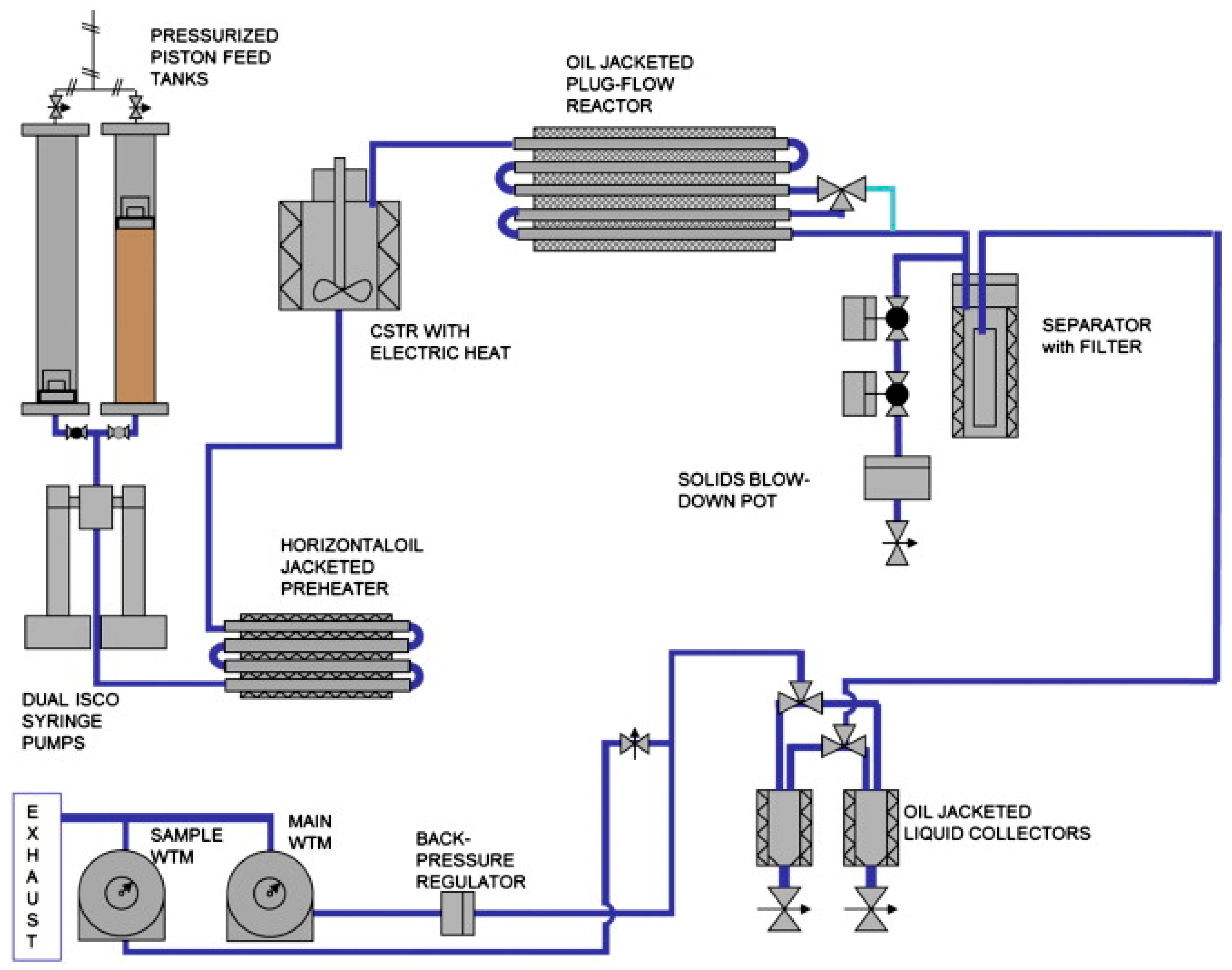
Figure 5.
Process scheme of the Continuous Bench-Scale (CBS1) plant built at Aalborg University, Denmark. Reproduced from [27], with permission from Elsevier, © Elsevier 2015.
Figure 5.
Process scheme of the Continuous Bench-Scale (CBS1) plant built at Aalborg University, Denmark. Reproduced from [27], with permission from Elsevier, © Elsevier 2015.

Figure 6.
Operations of the Hydrofaction™ process at the pilot plant at Aalborg University, operated by Steeper Energy. Reproduced from [13], with permission from Springer, © Springer-Verlag 2017.
Figure 6.
Operations of the Hydrofaction™ process at the pilot plant at Aalborg University, operated by Steeper Energy. Reproduced from [13], with permission from Springer, © Springer-Verlag 2017.

Figure 7.
Energy ratio vs. bio-crude yields for the continuous HTL studies in the open literature. Curves represent points with the same energy ratio. Circles: algal biomass; Squares: waste biomass; Triangles: wood; Diamonds: lignin.
Figure 7.
Energy ratio vs. bio-crude yields for the continuous HTL studies in the open literature. Curves represent points with the same energy ratio. Circles: algal biomass; Squares: waste biomass; Triangles: wood; Diamonds: lignin.

Figure 8.
Effect of dry matter concentration on the energy ratio and bio-crude yields for the continuous HTL studies in the open literature. Percentages indicate the dry matter concentration of biomass in the feed.
Figure 8.
Effect of dry matter concentration on the energy ratio and bio-crude yields for the continuous HTL studies in the open literature. Percentages indicate the dry matter concentration of biomass in the feed.

Figure 9.
Energy ratio vs. bio-crude yields for the continuous HTL studies in the open literature. Same symbolic nomenclature as in Figure 7.
Figure 9.
Energy ratio vs. bio-crude yields for the continuous HTL studies in the open literature. Same symbolic nomenclature as in Figure 7.

Figure 10.
Extent of deoxygenation (a) and denitrogenation (b) achieved in the HTL and following hydrotreating of the biocrude. Information on feedstock and catalyst can be found in Table 2.
Figure 10.
Extent of deoxygenation (a) and denitrogenation (b) achieved in the HTL and following hydrotreating of the biocrude. Information on feedstock and catalyst can be found in Table 2.


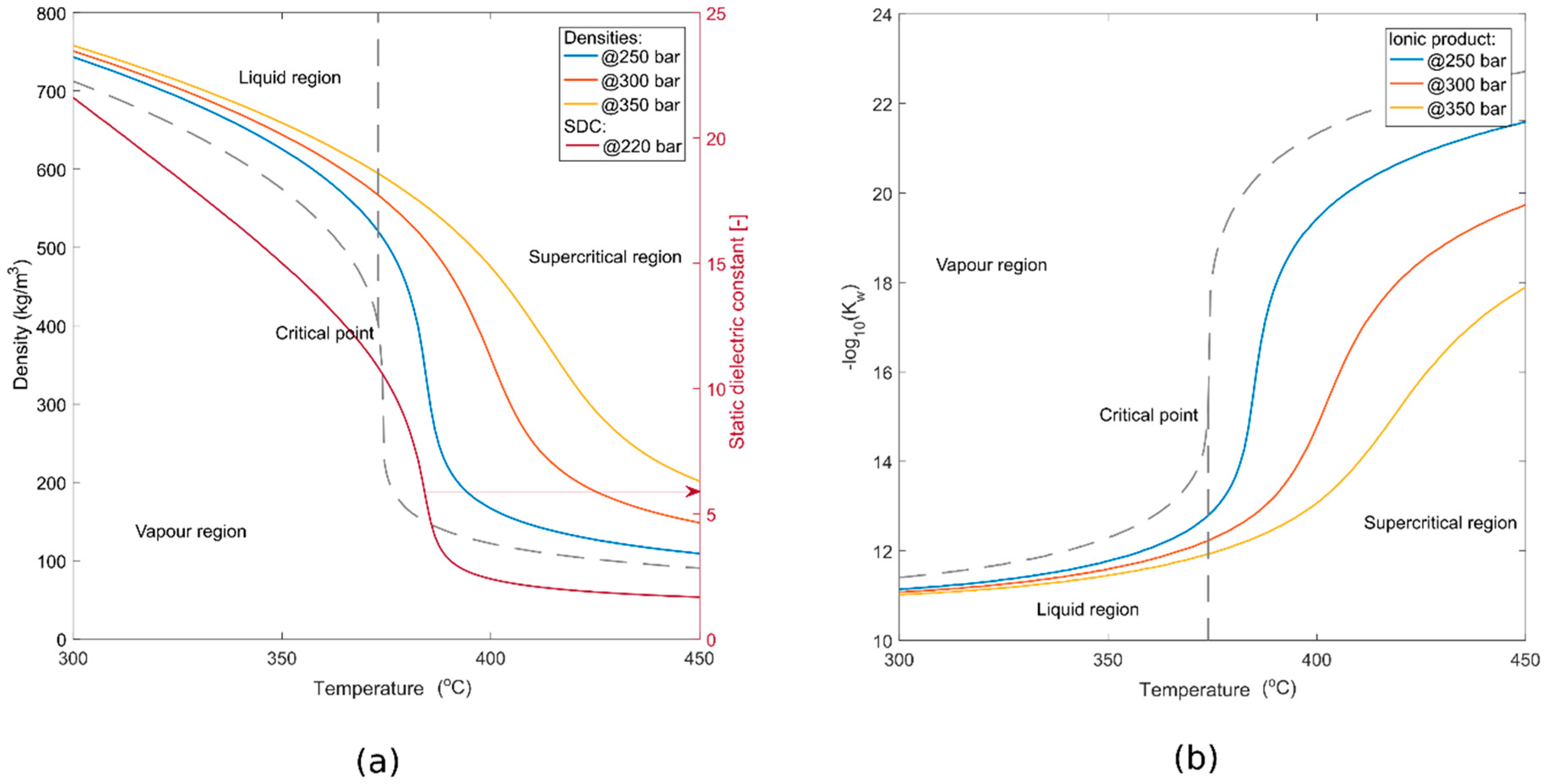
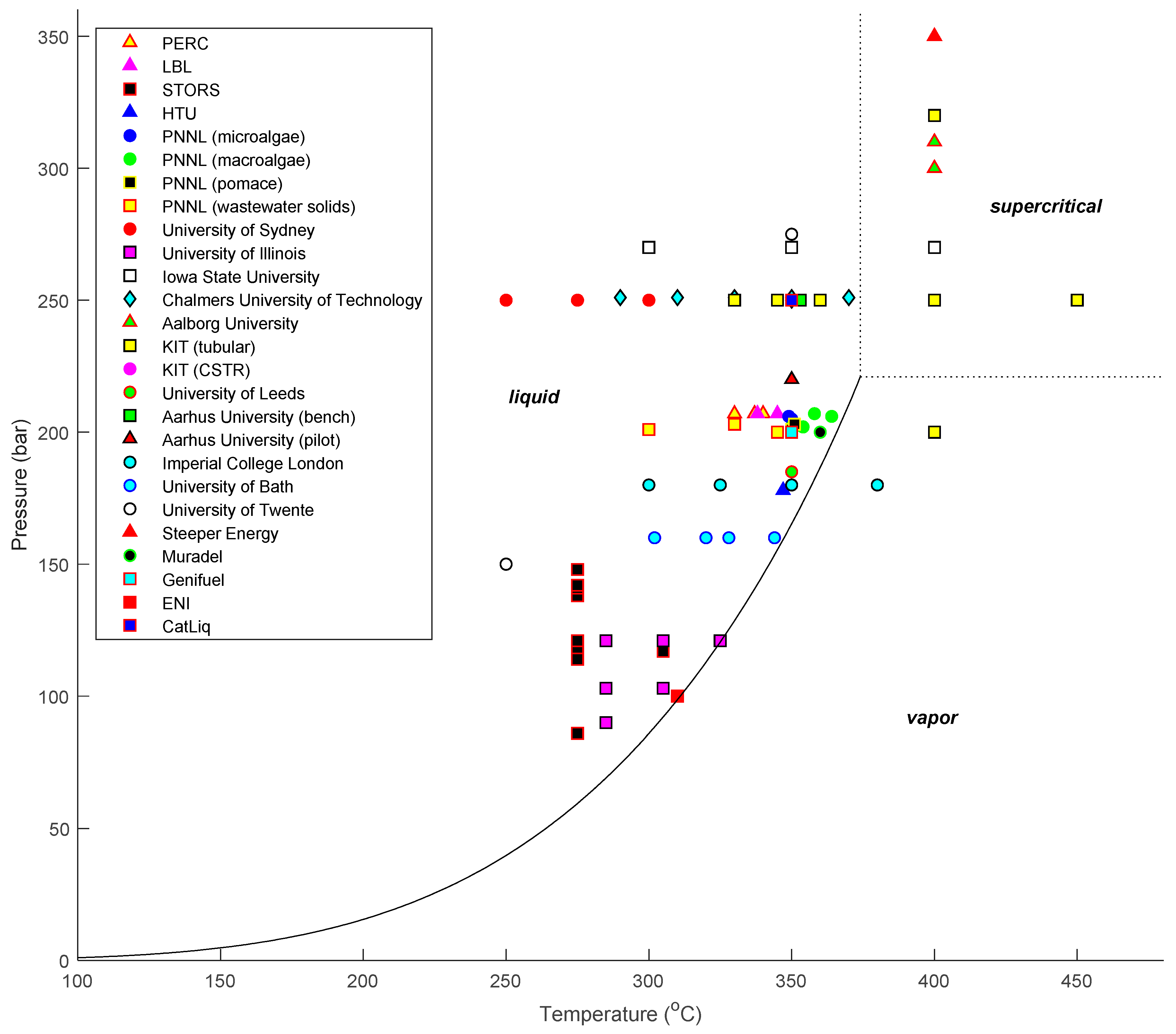
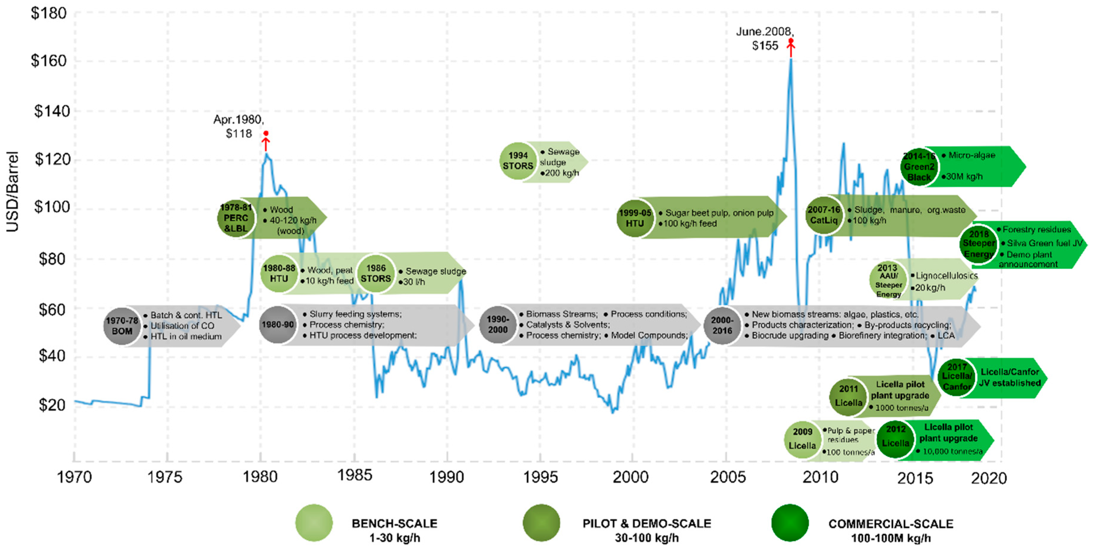
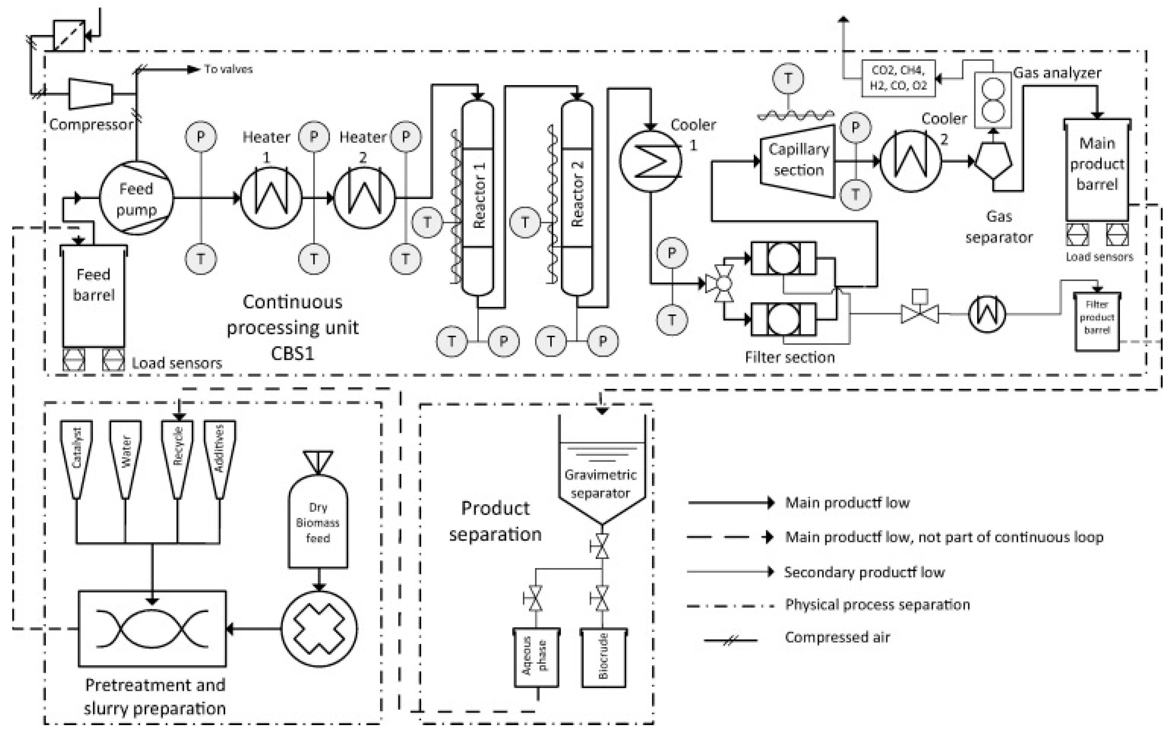
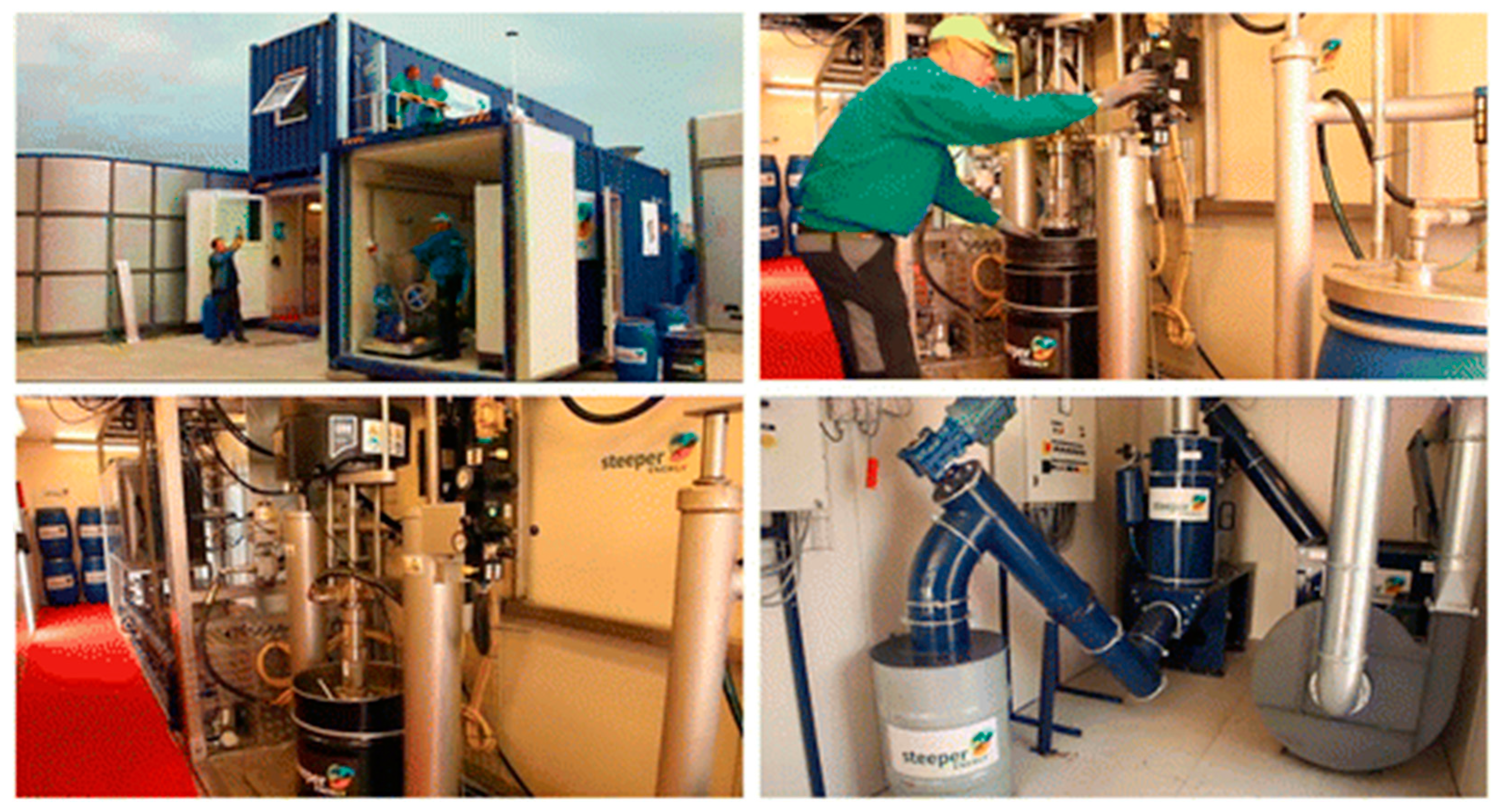
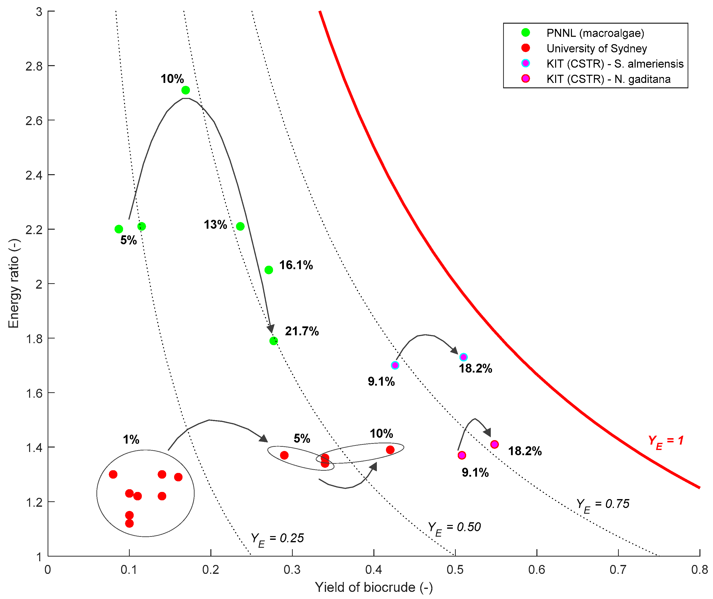
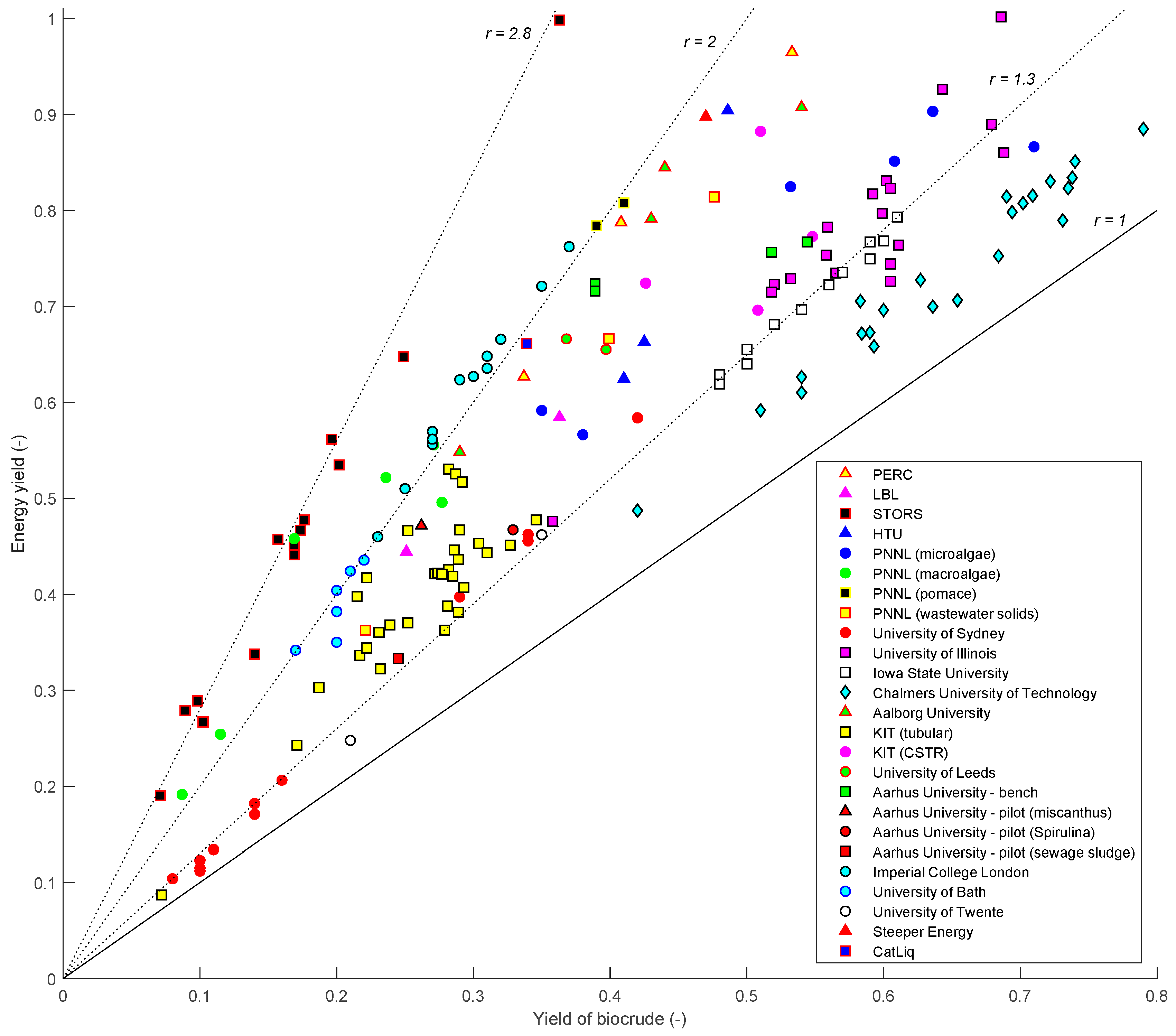
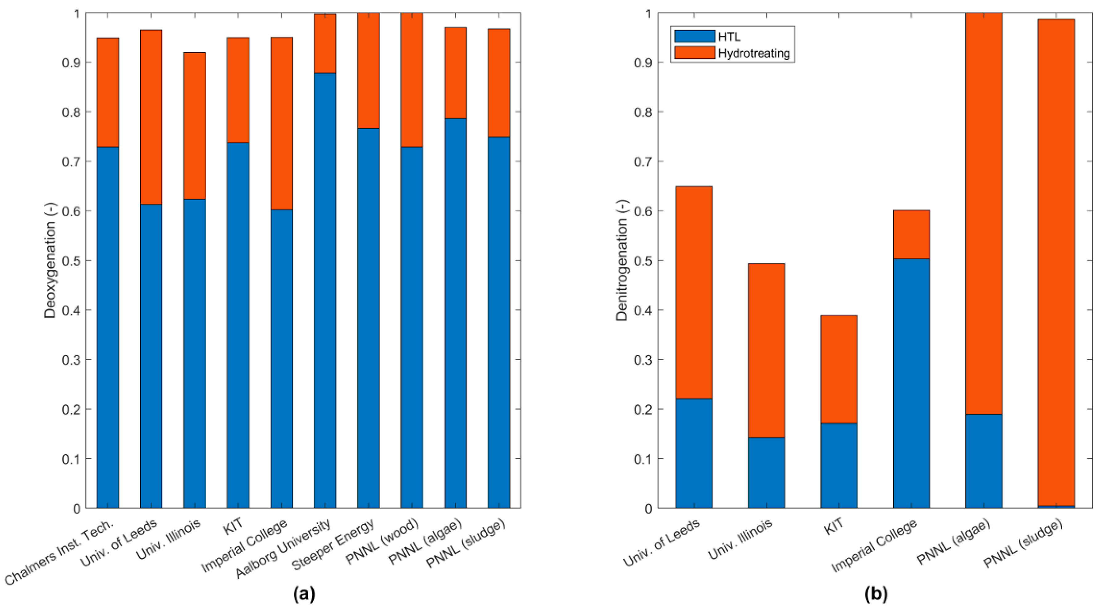
Table 1.
Continuous hydrothermal liquefaction (HTL) plants and setups documented in the literature.
| Process/Plant | Reactor Concept | Biomass | Throughput (kg/h) | Pressure (bar) | Temp. (°C) | Residence Time (min) | Catalyst | Ref. |
|---|---|---|---|---|---|---|---|---|
| PDU–PERC Albany, USA | Tubular/stirred | Wood | 230–270 | 207 | 330–340 | 19–100 | Na2CO3 | [36] |
| PDU–LBL Albany, USA | Tubular/stirred | Wood | 43–360 | 207 | 340–345 | 11.3–465 | Na2CO3 | [36] |
| LBL Berkeley, USA | Stirred | Wood | ~1 | 200–230 | 330–350 | ~20 | - | [37] |
| STORS–EPA, USA | Column | Sewage sludge | 30 | 86–148 | 275–305 | 90 | Na2CO3 | [38] |
| STORS–Organo Corp., Japan | Column | Sewage sludge | 240 | 88–98 | 290–300 | N/A | - | [39] |
| HTU® process Shell, The Netherlands | Tubular | Wood | 10 | 180 | 350 | 6 | - | [40] |
| HTU® process Biofuels B.V., The Netherlands | Tubular | Sugar beet pulp, onion pulp | 100 | 180 | 350 | 15 | - | [41] |
| Pacific Northwest National Laboratories (PNNL), USA | Stirred + tubular | Algae | 1.5 | 200 | 350 | 27–50 | - | [42,43] |
| Macroalgae | - | [44] | ||||||
| Grape pomace | Na2CO3 | [45] | ||||||
| Wastewater solids | - | [46] | ||||||
| University of Sydney, Australia | Coils in sandbath | Algae | 24–40 | 200–250 | 350 | 15–20 | - | [47,48] |
| University of Illinois, USA | Stirred | Swine manure | 0.9–2.0 | 103 | 305 | 40–80 | - | [49,50] |
| Iowa State University, USA | Tubular | Fungi | 3.0–7.5 | 270 | 300–400 | 11–31 | - | [51] |
| Chalmers University of Technology, Sweden | Fixed bed, with recycle loop | Kraft lignin | 1–2 | 250 | 350 | 6–11 | ZrO2, K2CO3 | [52,53,54,55,56] |
| Aalborg University, Denmark | Tubular | Wood/glycerol | 20 | 300–350 | 390–420 | 15 | K2CO3 | [27] |
| Wood | [28] | |||||||
| Karlsruhe Institute of Technology (KIT), Germany | Tubular, with recirculation | Waste biomass | 0.29–0.63 | 250 | 330–350 | 5–10 | K2CO3, ZrO2 | [57] |
| Tubular, with MeOH gasifier | Yeast, pomace | 0.06–0.61 | 200–250 | 330–450 | 1–30 | K2CO3, ZrO2 | [58,59] | |
| Stirred | Algae | 0.76 | 200 | 350 | 15 | - | [60] | |
| University of Leeds, UK | Coils in sandbath | Chlorella | 0.6–2.4 | 185 | 350 | 1.4–5.8 | - | [61] |
| Aarhus University, Denmark | Tubular (bench) | Dried digested grains with solubles | 0.36–1.44 | 250 | 250–350 | ~20 | K2CO3 | [62,63] |
| Tubular (pilot), with oscillator | Wood, sewage sludge, Spirulina | 60 | 220 | 350 | 10 | KOH, no | [64] | |
| Imperial College London, UK | Tubular, hexane as co-solvent | Algae | 0.03–0.24 | 180 | 300–380 | 0.5–4 | - | [65] |
| Bath University, UK | Concentric tubular | Wastewater algae | 0.18–0.42 | 160 | 302–344 | 17.7–41.8 | - | [66] |
| University of Twente, The Netherlands | Coils in sandbath | Scenedesmus sp. | 0.06–0.33 | 150–300 | 250–350 | 7–30 | - | [67] |
| Cat-HTR™ process Licella, Australia | N/A | Pulp/paper, plastics | 10,000 t/y 2 | N/A | N/A | N/A | Yes | [68] |
| Hydrofaction™ process Steeper Energy 3, Denmark-Canada | Tubular | Wood | 20 | 300–350 | 390–420 | 15 | K2CO3 | [13] |
| Green2black™ process Muradel, Australia | Tubular | Tires, algae | 168 | 200 | 360 | 10 | N/A | [69] |
| HTP process Genifuel, USA | Stirred + tubular 1 | Sewage sludge | N/A | 200 | 350 | 45 | N/A | [70,71] |
| W2F process ENI S.p.A., Italy | N/A | Organic fraction of municipal solid waste | 1–5 | 100 | 250–310 | 60–120 | N/A | [72,73] |
| CatLiq® process SCF Technologies, Denmark | Stirred | Wet digested grains with solubles | 30 | 250 | 350 | 1–15 | ZrO2 | [74] |
| CatLiq® process Altaca Enerji, Turkey | N/A | Different wastes and residues | 15,000 2 | 250 | 350 | N/A | Yes | [75,76] |
| TDP process Changing World Technologies, USA | N/A | Turkey waste | 8500 | N/A | 200–300 4 | N/A | - | [77,78] |
1 Genifuel utilizes the HTL concept developed at PNNL. 2 Announced scale-up throughput. 3 Reported activities by Steeper Energy take place in the same plant as Aalborg University. 4 Temperature of the first stage. The process includes a second stage for thermal cracking at 500 °C.
Table 2.
Main performance data of the biocrude upgrading studies based on continuous HTL.
| Location | Biomass | HTL Bio-Crude | Catalyst | Upgraded Bio-Crude | Overall Yield (wt. %) | C Yield (wt. %) | Ref. | ||
|---|---|---|---|---|---|---|---|---|---|
| HHV (MJ/kg) | H/C (-) | HHV (MJ/kg) | H/C (-) | ||||||
| Chalmers Institute of Technology, Sweden 1 | Wood | 36.3 | 1.38 | CoMo/Al2O3 | 42.5 | 1.44 | N/A | N/A | [106,108] |
| University of Leeds, UK | Algae (Chlorella) | 36.1 | 1.55 | NiMo | 41.5 | 1.57 | 34.3 | 49.0 | [61] |
| University of Illinois, USA 2 | Algae (Chlorella) | 35.7 | 1.45 | Pd/C | 43.1 | 1.64 | 26.5 | 38.7 | [110] |
| Karlsruhe Institute of Technology, Germany | Algae (Scenedesmus) | 36.3 | 1.52 | Pt/Al2O3 | 41.9 | 1.60 | 31.5 | 54.9 | [112] |
| HZSM-5 | 40.7 | 1.50 | 31.5 | 54.2 | |||||
| Algae (Nannochloropsis) | 37 | 1.63 | Pt/Al2O3 | 43.2 | 1.67 | 33.9 | 52.6 | ||
| HZSM-5 | 42.3 | 1.62 | 27.6 | 42.5 | |||||
| Imperial College London, UK | Algae (Nannochloropsis) | 36.5 | 1.58 | NiMo/Al2O3 | 38.3 | 1.89 | 35.7 | 60.0 | [111] |
| Ru/Al2O3 | 43.9 | 1.67 | 23.5 | 45.0 | |||||
| Pt/Al2O3 | 45.4 | 1.78 | 23.5 | 45.2 | |||||
| Pd/Al2O3 | 44.2 | 1.73 | 24.1 | 45.7 | |||||
| Pt/C | 44.9 | 1.78 | 24.1 | 46.0 | |||||
| Ru/C | 43.7 | 1.77 | 25.9 | 48.5 | |||||
| Pd/C | 42.2 | 1.76 | 26.6 | 48.8 | |||||
| Aalborg University, Denmark | Aspen wood | 38.6 | 1.40 | NiMo/Al2O3 | 41.1 | 1.57 | N/A | N/A | [114] |
| Hardwood | 40.4 | 1.48 | NiMo/Al2O3 | 43.9 | 1.67 | N/A | N/A | [113] | |
| Steeper Energy, Denmark-Canada | Pine/spruce | 37.2 | 1.34 | NiMo/Al2O3 | 42.2 | 1.57 | 36.0 | 63.3 | [25] |
| 38.0 | 1.34 | NiMo/Al2O3 | 43.2 | 1.71 | 38.1 | 66.1 | |||
| 38.6 | 1.26 | NiW/SiO2/Al2O3 Pd/Al2O3 | 43.5 | 1.58 | N/A | N/A | |||
| Pacific Northwest National Laboratory (PNNL), USA | Wood 1 | 36.3 | 1.29 | CoMo/Al2O3 | 45.2 | 1.75 | N/A | 68.9 | [106] |
| Algae (Solix) | 39.5 | 1.52 | CoMo/Al2O3 | 46.3 | 2.00 | 42.3 | 72.3 | [116] | |
| Algae (NB238) | 39.8 | 1.59 | CoMo/Al2O3 | 45.4 | 1.87 | 32.1 | 57.5 | ||
| Algae (Cellana low lipid) | 39.5 | 1.62 | CoMo/Al2O3 | 45.2 | 1.92 | 51.4 | 83.5 | ||
| Algae (Cellana high lipid) | 39.9 | 1.63 | CoMo/Al2O3 | 45.7 | 2.00 | 51.3 | 83.9 | ||
| Algae (Chlorella standard lipid) | 39.4 | 1.47 | CoMo/Al2O3 | 45.6 | 1.98 | 30.1 | 53.1 | [43] | |
| Algae (Chlorella high lipid) | 39.4 | 1.72 | CoMo/Al2O3 | 47.1 | 2.04 | 63.9 | 86.8 | ||
| Primary sludge | 37.9 | 1.57 | CoMo/Al2O3 | 46.1 | 2.00 | 28.6 | 50.7 | [46] | |
| Digested solids | 38.1 | 1.40 | CoMo/Al2O3 | 45.7 | 1.92 | 32.0 | 70.5 | ||
1 Biocrudes obtained from the campaigns at the Albany process development unit (PDU-PERC, PDU-LBL). 2 HTL experiments performed at the University of Leeds.
© 2018 by the authors. Licensee MDPI, Basel, Switzerland. This article is an open access article distributed under the terms and conditions of the Creative Commons Attribution (CC BY) license (http://creativecommons.org/licenses/by/4.0/).
Share and Cite
MDPI and ACS Style
Castello, D.; Pedersen, T.H.; Rosendahl, L.A. Continuous Hydrothermal Liquefaction of Biomass: A Critical Review. Energies 2018, 11, 3165. https://doi.org/10.3390/en11113165
AMA Style
Castello D, Pedersen TH, Rosendahl LA. Continuous Hydrothermal Liquefaction of Biomass: A Critical Review. Energies. 2018; 11(11):3165. https://doi.org/10.3390/en11113165
Chicago/Turabian StyleCastello, Daniele, Thomas Helmer Pedersen, and Lasse Aistrup Rosendahl. 2018. "Continuous Hydrothermal Liquefaction of Biomass: A Critical Review" Energies 11, no. 11: 3165. https://doi.org/10.3390/en11113165
Note that from the first issue of 2016, this journal uses article numbers instead of page numbers. See further details here.