Article

Research on Commutation and Coordination Control Strategy of Excitation Power Supply Based on Bidirectional Reduced Matrix Converter for Ion Accelerator

1
School of Automation and Information Engineering, Xi’an University of Technology, Xi’an 710048, Shaanxi, China
2
Institute of Modern Physics Chinese Academy of Sciences, Lanzhou 730000, China
3
State Key Laboratory of Large Electric Drive System and Equipment Technology, Tianshui, Gansu 741020, China
*
Author to whom correspondence should be addressed.
Energies 2018, 11(12), 3396; https://doi.org/10.3390/en11123396
Submission received: 28 October 2018 / Revised: 26 November 2018 / Accepted: 26 November 2018 / Published: 4 December 2018
(This article belongs to the Section F: Electrical Engineering)

Abstract

:
The contribution of this paper is putting forward a kind of ion accelerator magnet excitation power supply with bidirectional reduced matrix converter (BRMC) as well as a coordination control strategy with bipolar current space vector modulation strategy, which is utilized to realize bidirectional power flow for a BRMC system to solve problems such as low input power factor, large input current harmonics and no bidirectional energy in the conventional ion accelerator magnet excitation power supply. Meanwhile, a hybrid commutation strategy combining the simplified three-step commutation with zero vector commutation was proposed to solve the commutation problem for a matrix-type first stage in BRMC. The feasibility and effectiveness of the proposed strategy, which can achieve bidirectional energy flow and safer commutation, have been verified by the experimental results.

1. Introduction

Ion accelerators have been widely used in scientific research, medicine, aerospace, military and other fields. The output power range of accelerator magnet excitation power supplies ranges from several thousand watts to megawatts. Ion accelerator has broad application prospects in engineering physics and medical field, for which the key device is the excitation power supply. The new accelerator proposes higher criteria requirement for excitation power such as energy bidirectional flow, energy saving characteristics, sinusoidal input current, unit power factor and grid green pollution-free. Therefore, it is imperative to find a “green” and energy-saving excitation power supply with high regulation accuracy and fast dynamic response in order to solve the above-mentioned problems.
The conventional topology used for this excitation power supplies are mainly Buck DC chopper converter, H bridge DC chopper topology, multi pulse rectifier and so on [1,2,3,4]. However, conventional ion accelerator magnet excitation power supplies have some disadvantages. These include low power factor, large harmonic pollution and the energy not being able tobe recovered [5,6]. At the same time, this kind of accelerator requires that the power supply have the function of energy feedback which can reclaim excess energy in the magnet to the grid. Then a “green” power supply with high power factor, sinusoidal input current and the function of energy feedback to overcome these aforementioned problems is necessary.
Reference [7] proposed a dipole magnet power supply which can convert AC into DC based on phase-controlled rectifier with thyristor-technology. However, the problems of low power factor, large volume and low energy conversion efficiency still exist. Reference [8] proposed a multilevel voltage type rectifier + half bridge inverter + voltage doublers rectifier topology with great improvements on grid side performance, but this topology also has the disadvantages of more converter stages with low efficiency and complex close-loop control. In addition, these conventional excitation power supplies cannot realize bidirectional power flow. BRMC evolving from matrix converter (MC) is a new-type power electronic converters topology. Reference [9,10] indicated that Reduced Matrix Converter (RMC) system had excellent input and output performance involving unit power factor and sinusoidal input current; and it can achieve less conversion stage and higher power density. Therefore, the BRMC system is used as the magnet excitation power supply for ion accelerator in this paper. Meanwhile the paper also proposes a coordination control strategy with bipolar current space vector modulation strategy to realize bidirectional power flow without complex close-loop control and extra hardware circuits.
It is known that commutation should be achieved without causing short circuits for the input phases and open circuits for the inductive load current, which will cause over current and voltage to destroy the devices in a matrix-type matrix. Reference [11] proposed a four-step commutation method based on the direction of output current. However, this method will cause the problem of commutation failure and short circuits when the direction information of small currents is wrongly judged. Reference [12] proposed a four-step commutation method based on input voltage of relative size, however, the disadvantages of this method are that the requirement of the voltage detection device is high, temperature drift and zero drift of the detection device can easily cause judgment mistakes, and a short-circuit would occur if there is a voltage reversal during the commutation. There are also other commutation strategies as presented in papers such as references [13,14]. But this paper puts forward a new hybrid commutation strategy combining simplified three-step commutation with zero vector commutation to solve an important problem for the reliable and safe operation of BRMC.
The contribution of this paper is the proposition of a BRMC excitation power topology with bidirectional energy flow and its coordinated control method according to the requirement of the accelerator performance and the variation law of the exciting current. Meanwhile, in order to improve the reliability of BRMC, a more appropriate hybrid commutation strategy combining simplified three-step commutation with zero vector commutation is proposed according to the characteristics of BRMC modulation strategy and the actual situation of the load. Finally, an experimental prototype based on DSP + CPLD was built to verify the effectiveness of the proposed methods.
This article is divided into 7 parts as follows: Section 1 gives a general account of the research background and problems that need to be solved. This paper outlines the improvements it makes on the basis of existing theories. Section 2 compares the proposed topology with the existing ones. Meanwhile, it highlights the advantages of BRMC, which is more suitable for ion accelerator power supplies. Section 3 introduces the coordinated modulation strategy presented in detail in this paper. It includes the B-C-SVM for the front stage and the coordination strategy of the latter stage to achieve bidirectional energy flow. Section 4 introduces the new hybrid commutation proposed in this paper. Section 5 and Section 6 are to verify the effectiveness of the methods proposed in this paper and the experimental waveforms strongly proved their correctness. Section 7 is the conclusion of this paper.

2. Topology of BRMC

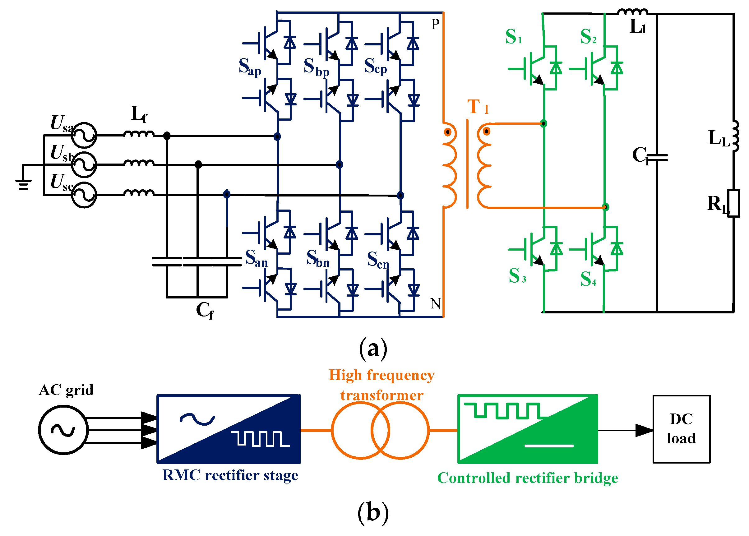
There are two kinds of AC/DC converter topologies which can meet the aforementioned requirements for ion accelerator magnet excitation power supplies. One is the conventional converter consisting of PWM Rectifier Bridge + Dual Active Bridge (PRB-DAB) as shown in Figure 1a. Its schematic diagram of power flow is shown in Figure 1b. The other is the topology of BRMC as shown in Figure 2a, whose schematic diagram is shown in Figure 2b. It consists of three parts: a matrix converter stage, a high frequency transformer and a controlled rectifier bridge. Comparing Figure 1b with Figure 2b, it is easy to determine that the converter stage can efficiently reduce the three stages in PRB-DAB to two stages in BRMC.
Comparing the two topologies, it can be found that BRMC leaves out the intermediate full bridge inverter with energy storage capacitor. Moreover, BRMC has lots of advantages such as high efficiency and power density, electrical isolation, low cost and voltage regulation using a high-frequency transformer with small volume and low cost. Some results of the comparative evaluation of these two topologies are compiled in Table 1.

3. Coordinated Control Strategy for BRMC

The BRMC coordinated control strategy is designed to meet the performance requirement of ion accelerator magnet citation power supplies. The strategy of the BRMC rectifier stage adopts bipolar current space vector modulation (B-C-SVM), and its function is to convert three-phase alternating current into a symmetrical and periodic square wave [15]. The latter controlled rectifier bridge should be synchronized with the BRMC rectifier stage to achieve bidirectional power flow.

3.1. B-C-SVM for the BRMC Rectifier Stage

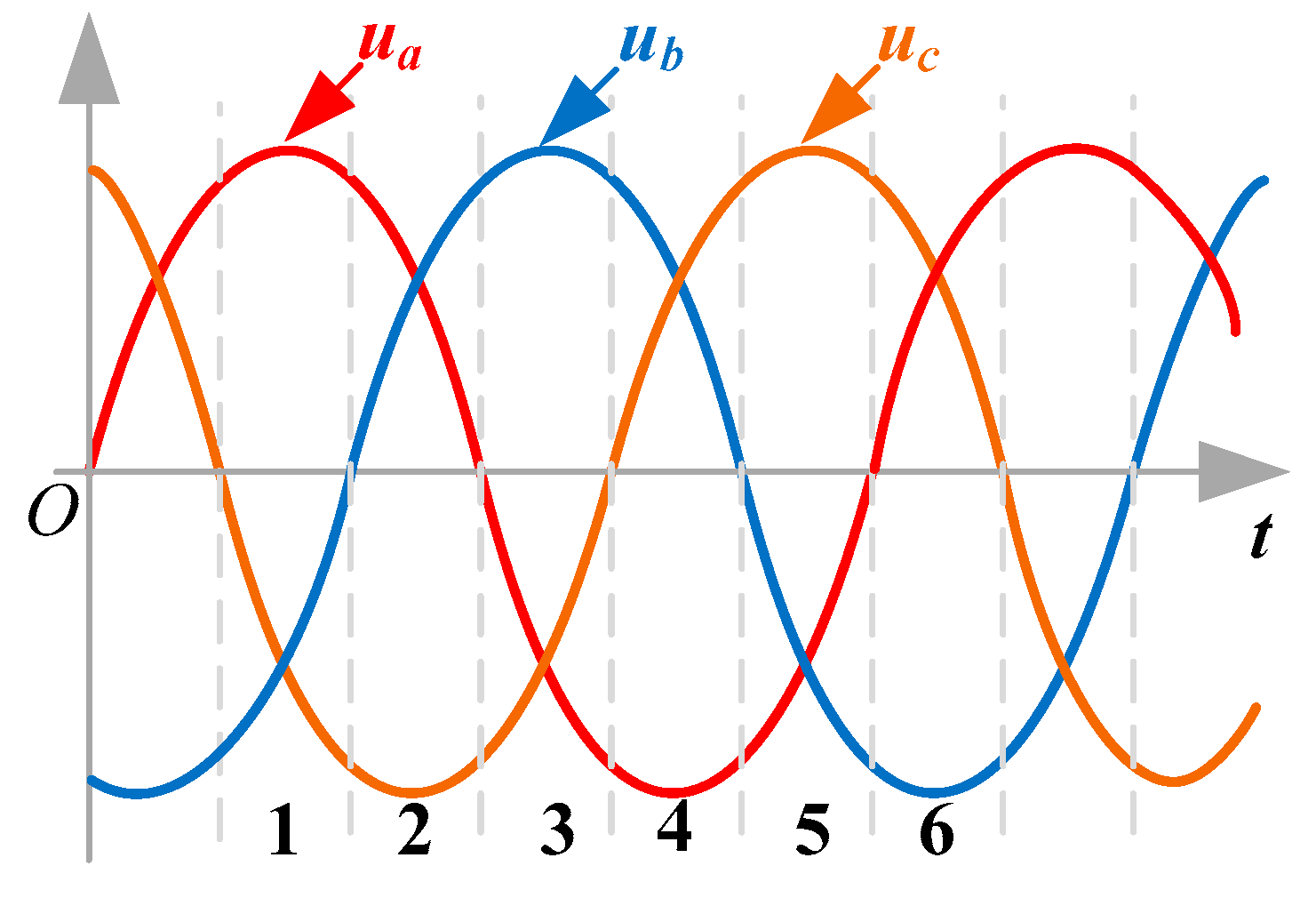
Sector division of B-C-SVM is shown in Figure 3. The input voltages are divided into 6 sectors. In each sector, the mode of the phase with maximum amplitude is a constant, and the other two phases are modulated. In a conventional current source converter, two adjacent active vectors and one zero vector are enough to generate the desired output current. But for BRMC, it is necessary to generate not only the desired three phase input current but also the desired output square wave current. In consequence, at least five vectors are needed: two adjacent vectors to generate the positive part of Iout; two opposite vectors to generate the negative part of Iout and a zero vector to complete the array [16,17]. Take the first sector as an example. Active vectors Iab, Iac and zero vector Iaa composite vector Iref in the first half switching period; Active vectors Iba, Ica and zero vector Iaa composite vector −Iref in another first half period of switching period. The vector diagram is shown in Figure 4. Vector Iref and −Iref have the same amplitude, but opposite direction and actuation duration (half the switching period).
Suppose the three-phase input voltages are as follows:
{ u s a = U i cos ( ω i t ) u s b = U i cos ( ω i t 2 π / 3 ) u s c = U i cos ( ω i t + 2 π / 3 )
where Ui is the phase voltage of grid side and ωi is the angular frequency of phase voltage.
In order to get unit power factor on grid side, the phase current of grid side can be expressed as:
i s = [ i s a i s b i s c ] = I i n [ cos ω i t cos ( ω i t 2 π / 3 ) cos ( ω i t + 2 π / 3 ) ]
where Iin is the phase current amplitude on grid side.
The reference current is composed by vectors (Iab, Iac and Iaa) in first sector at the positive half period of the current. According to the rule of space vector synthesis shown in Figure 4, the action time of each vector can be derived as follows:
{ t x = m s s i n ( π / 3 θ in ) T s 2 t y = m s s i n ( θ in ) T s 2 t 0 = ( 1 d γ d δ ) T s 2
Therefore, the duty cycle of each vector can be derived as:
{ d α = 2 T s t α = m s s i n ( π / 3 θ i n ) d β = 2 T s t β = m s s i n ( θ i n ) d 0 = 1 d α d β
where ms is the modulation index and θin is the angle of the oriented current vector.
In order to obtain the unity power factor and considering that the phase error between the three-phase reference input current and the three-phase voltage is zero; θin can be obtained in the first sector as:
θ i n = ω i t + π / 6
It can be obtained from Equation (5) to (4) that:
{ d α = m s c o s ( ω i t 2 π / 3 ) d β = m s c o s ( ω i t + 2 π / 3 ) d 0 = 1 m s c o s ( ω i )
In order to facilitate calculation, the three-phase reference input phase current is defined as:
{ i s a = c o s ( ω i t ) i s b = c o s [ ( ω i t 2 π / 3 ) ] i s c = c o s [ ( ω i t + 2 π / 3 ) ]
According to Equations (6)–(8), the duty cycle of the first sector can be calculated as:
{ d x = 2 T s t x = m s i s b d y = 2 T s t y = m s i s c d 0 = 1 d x d y = 1 m s i s a
The duty cycle formulas of the other 5 sectors are shown in Table 2. The output voltage in BRMC is the current in the high frequency transformer. In this case, the polarity of the adjacent vectors is changed to achieve square waveform. The effect brought by the alternation of this switching signal is compensated by the full bridge.
Figure 5 shows the operating modes of BRMC rectifier stage when the active vectors work in the first sector. As aforementioned, one period is split into two equal periods. The primary voltage of the transformer is positive when Sap is normally turned on and is negative when San is normally turned on in the first sector. In the positive half period, the primary voltage of transformer is Uab as shown in Figure 6, when the current operating mode is Uab as shown in Figure 5a. Similarly, the next primary voltages of transformer are Uac and Uaa, respectively. And they correspond to mode of Uac and mode of Uaa in Figure 5, respectively. There is the same form of the primary transformer voltage when the switch San normally turned on in the negative half period. The primary transformer voltages Uba, Uca and Uaa in Figure 6 correspond to the mode in Figure 5d–f, respectively.

3.2. CoordinationStrategy of Controlled Rectifier Bridge

Considering of the particularity of BRMC topology and the bidirectional power flow of the magnet load, the control signals of the controlled rectifier bridge are different in the energy forward mode and the energy feedback mode.

3.2.1. Energy Forward Mode

The principle waveforms of energy forward mode and energy feedback mode in the first sector are shown in Figure 7. The waveforms belong to three-phase voltage, switching state of the BRMC rectifier stage, primary voltage of transformer UPN, primary current of transformer IPN, drive signals of IGBT S1 and S4, drive signals of IGBT S2 and S3, output voltage U0 and output current I0repectively. In the first sector, the control signals of the BRMC rectifier stage follow the upper part of the B-C-SVM. The primary voltage of the transformer is positive and the primary side current of the transformer is in phase with the voltage when switch Sap is normally turned on and Sbn, Scn, San are sequentially turned on in the phase A. Then the primary voltage of the transformer is negative and the primary side current of the transformer is in phase with the voltage when switch San is normally turned on and then Sbp, Scp, Sap are sequentially turned on with the opposite active vector. All other control signals of the controlled rectifier bridge are closed.
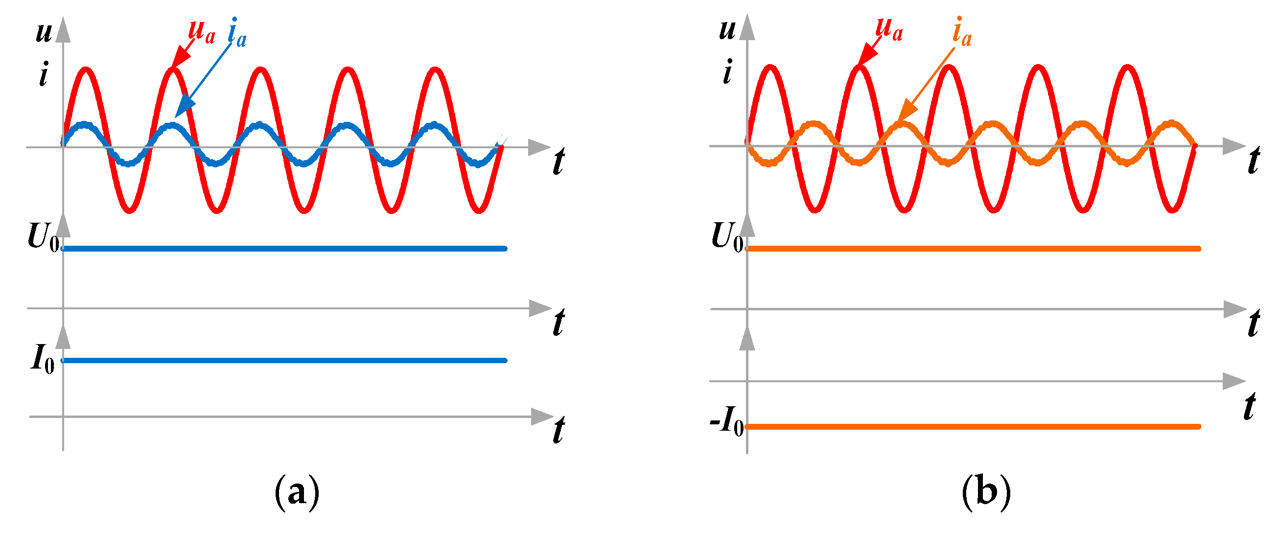
As shown in Figure 8a, the input voltage and current present unit power factor and the output voltage and current are both positive. The system works in energy forward mode.

3.2.2. Energy Feedback Mode

The symmetrical and periodic square wave signal of the BRMC first stage output is shown in Figure 5. The drive signals of the second stage of BRMC need to be coordinated with the output voltage signal of the first stage to realize the energy feedback function in feedback mode.
Figure 7 shows the three-phase voltage in the first sector, switching state of the BRMC rectifier stage, primary voltage of transformer UPN, primary current of transformer IPN, drive signals of IGBT S1 and S4, drive signals of IGBT S2 and S3, output voltage U0 and output current I0 respectively. In energy feedback mode, the drive signals of the BRMC rectifier stage are the same as those in energy forward transmission mode. When the switching signal is turned on, switch tubes S1 and S4 turn on, and switch S2 and S3 turn off when the switching signal is turned off. Thus, the voltage and current of the primary side of the transformer are reversed, the output voltage is positive, the output current is negative, and the energy feedback is realized. As shown in Figure 8b, the input voltage and current present the opposite phase and the output voltage and current are positive and negative, respectively. The system is in energy feedback mode. The specific conduction rule of the switches is shown in Table 3.
The aforementioned control of switches (S1, S2, S3 and S4) is only related to the polarity of transformer primary voltage. As shown in Figure 6a, the positive transformer primary voltage is Uab in energy forward transmission mode. Also, the current flows through the parallel diode of this switch for the controlled rectifier bridge.
So, S1 and S4 are opened as shown in Figure 6 when the system is in energy feedback mode. Current flows through the IGBT of the second stage of BRMC. Similarly, the negative transformer primary voltage is Uba shown in Figure 5d in energy forward transmission mode and S2 and S3 are opened in energy feedback mode. Figure 9 shows two new operating modes under different transformer primary voltage operating conditions.

3.2.3. Comparison between the Proposed Method and the Other Methods

Reference [18] presented a bidirectional power flow control method based on two loops mode switching according to different duty cycle ratio for an interleaved three-level bi-directional DC-DC converter for an application in the energy storage system, but the regulator parameters of two loops must be the same to ensure smoothly switching of power flow direction, which is at the cost of performance. Reference [19] presented a voltage and current regulation control method with a two-mode conversion for a bi-directional power flow solution in energy storage system fed by isolated AC-DC matrix converter, this bi-directional power flow function is realized by using a mode conversion between a set-current and DC-link voltage control based on a complex closed loop system. The coordination control is adopted in this paper for BRMC to make the energy flow in both directions as shown in Figure 10, which can be flexible switching between two modes according to the magnetic field energy requirements of the ion accelerator. It not only ensures the normal operation of the accelerator, but also ensures that the input current harmonic is still small, which meets the requirements of the power grid. Furthermore, the proposed method can realize bidirectional power flow to save energy without sacrificing performance or adding complex close-loop control compared with reference [18,19]. Moreover, this strategy is simple to implement, and is more reliable in practical application.

4. Hybrid Commutation Strategy of BRMC

Since BRMC is evolved on the basis of the conventional matrix converter (MC), both of them follow the same commutation constraints, that is, the load cannot be in an open circuit due to its inductive nature and input phase cannot be in a short circuit. According to the B-C-SVM above, the commutation problem and the exchange of positive and negative current vector can both cause voltage spike. Such as, one of the key technologies of BRMC is to ensure the safe commutation for bidirectional switches to realize the stability of input and output as the output of the BRMC rectifier stage is high frequency AC symmetrical pulse and the current direction switch is very fast. Aiming at BRMC commutation problems, the four-step commutation strategy of voltage and current is also analyzed and improved. Then a hybrid commutation strategy combining three-step commutation with zero vectors is proposed.
The BRMC topology adopts B-C-SVM strategy, and the positive and negative direction of the primary side current of the transformer can be obtained by the current polarity switching signal, so the current direction doesn’t need to be detected. Compared with the current four-step commutation, it avoids the risk of small current detection failure, ensures the safety of the commutation process, and improves the reliable operation of BRMC. Considering that the turn-off time of the IGBT is much longer than the turn-on time in practice, the two steps of the four-step commutation can be merged into one step, which will reduce the time interval of the commutation and form a three-step commutation. Suppose that the Sap is normally turn-on, the current is switched from B to C, and the commutation process is shown in Figure 11. Where as shown in Figure 12, Sbn+ represents the lower switch of the B bridge arm bidirectional switch Sbn and Sbn− represents the upper switch of the B bridge arm bidirectional switch Sbn.
With the above-mentioned commutation logic relation between the two phases, the commutation processes of each phase can be deduced as in Figure 13. In each switching period, there is one normally opened switch with three switches usa, usb and usc opened in turn at the contrary bridge arm. The 6 bits shown in Figure 12 represent three sequential switch tubes. For example, when Sap normally turns on, 6 bits represent the switch state of San, Sbn and Scn. Its order is San+-San−-Sbn+-Sbn−-Scn+-Scn−. 1 represents that the corresponding bidirectional switch is turn on, and 0 represents the turn off. Take the first sector in positive process as an example, Sap+and Sapare always turn-on. The 6-digit number represents the switching state of San+-San−-Sbn+-Sbn−-Scn+-Scn− in turn. It means that San+ and San- are turned-on and others are turned-off. Similarly, 00-11-00 represents that Sbn+ and Sbn are turned-on and others are turned-off. So the process of usa converting to usb is divided into three step. The first step is closing the San− drive. The second step is opening the Sbn+ drive and closing San+ drive. The third step is opening the Sbn− drive. The whole process is from 110000 to 100000, then to 001000, and finally to 001100.
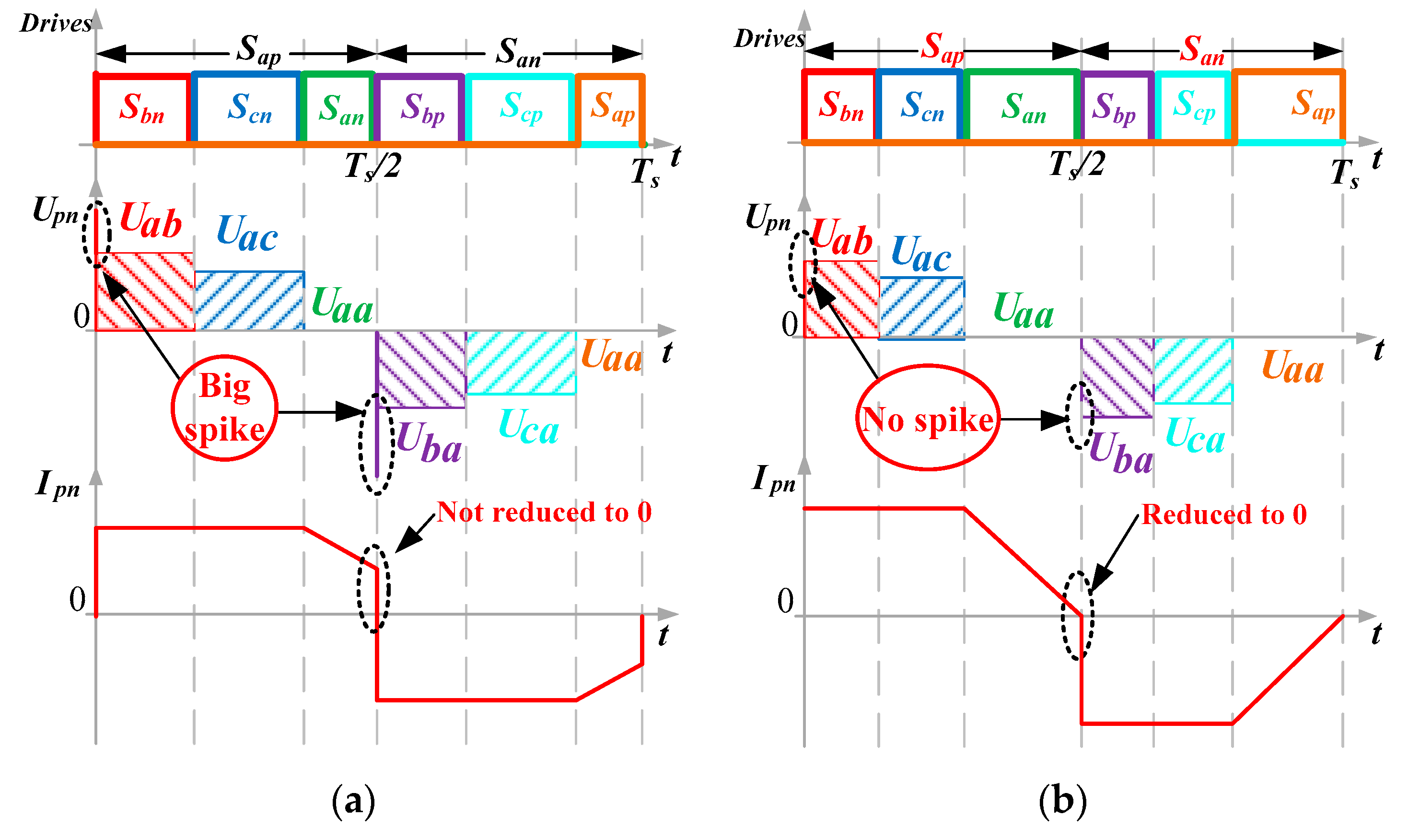
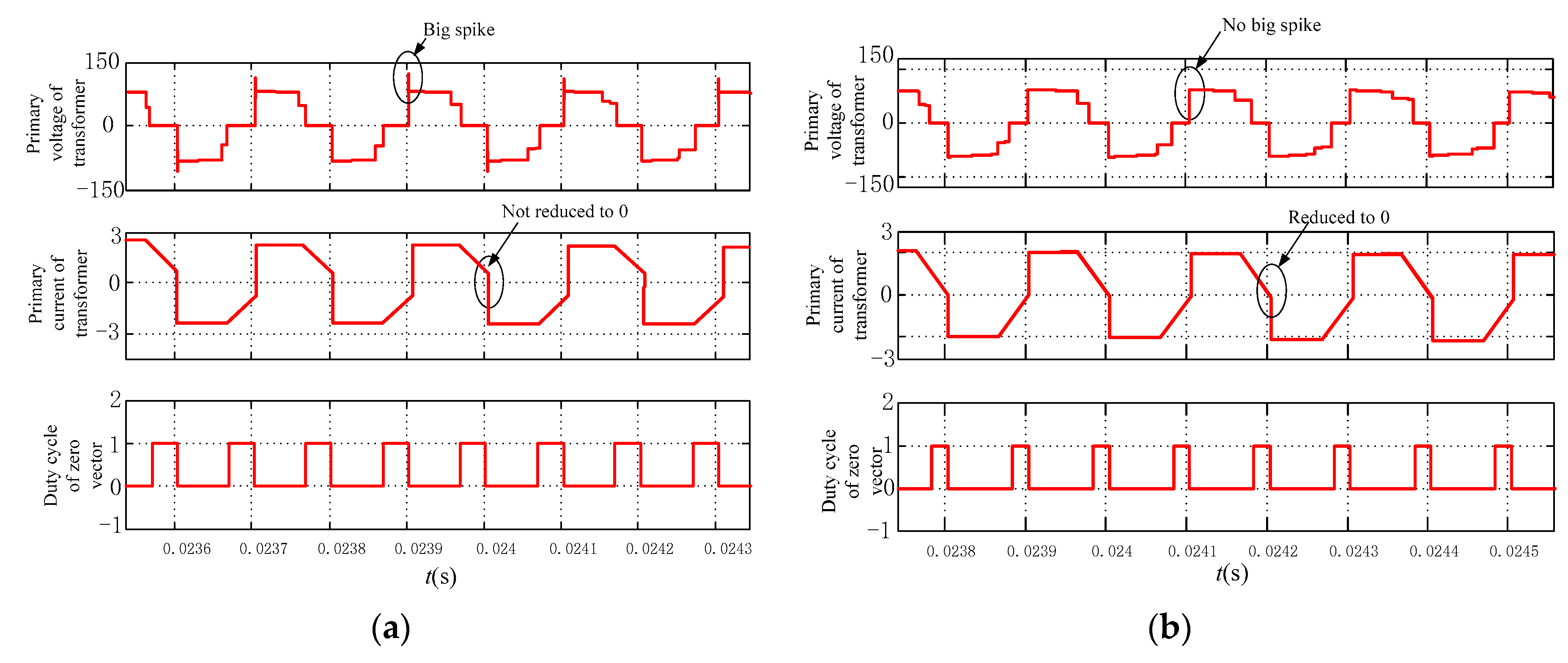
There are two types of transformer primary voltage spikes. One is “big spike” caused by currents switching from one bridge arm to another bridge arm in the same pole vector. The other is “small spike” caused by current switching from positive to negative in one cycle. The three-step commutation can guarantee commutation safety of the same pole vector. But it has nothing to do with the big spike. The current has a large amount of changes from positive to negative. Therefore, in this paper, the zero vector commutation is proposed to ensure the safety commutation at current switch-over point between positive and negative currents.
As shown in Figure 14a, the big spike of the transformer primary voltage exists when the transformer primary current doesn’t reduce to zero in the positive and negative switch-overas the zero vectors is too small in a cycle. In the respect of the big spike, this paper put forward a commutation method of increasing the action time of zero vectors. As shown in Figure 14b, the transformer primary current reduces to zero at the positive and negative switch-over point because of the longer action time of zero vectors. Thus, the current variation will be reduced at the positive and negative switch-over point. So, the larger the duty ratio of zero vectors is, the smaller the change of current is, and the minimum the voltage spike is.
The comparison between the hybrid commutation method and the other methods mentioned in literatures are carried out. Reference [20] introduced a two-step commutation method based on field-programmable gate array in which the output current direction was needed. However, the measurement and implementation hardware are complex and expensive. Reference [21] proposed an improved four-step commutation method based on the traditional four-step commutation. It simplifies the first and fourth steps and raises the effective working time of matrix converter, but a four-step commutation board is needed. Therefore, a hybrid commutation method combining three-step commutation with zero vector commutation is proposed in this paper. Among them, the three-step commutation guarantees commutation safety for the same pole vector while the zero vector commutation guarantees commutation safety for the positive and negative switch-over point. As for the particularity of BRMC, the existence of positive and negative switching signals saves the measurement of output current. Meanwhile, compared with the four-step commutation, the commutation introduced in this paper reduces commutation time. Finally, on the premise of safe commutation with the same polarity, a zero vector commutation is proposed to reduce the voltage spike at the positive and negative switching points. Thus, this hybrid commutation scheme combining three-step commutation with zero vectors is used to ensure safe commutation.

5. Implementation and Prototype of BRMC System

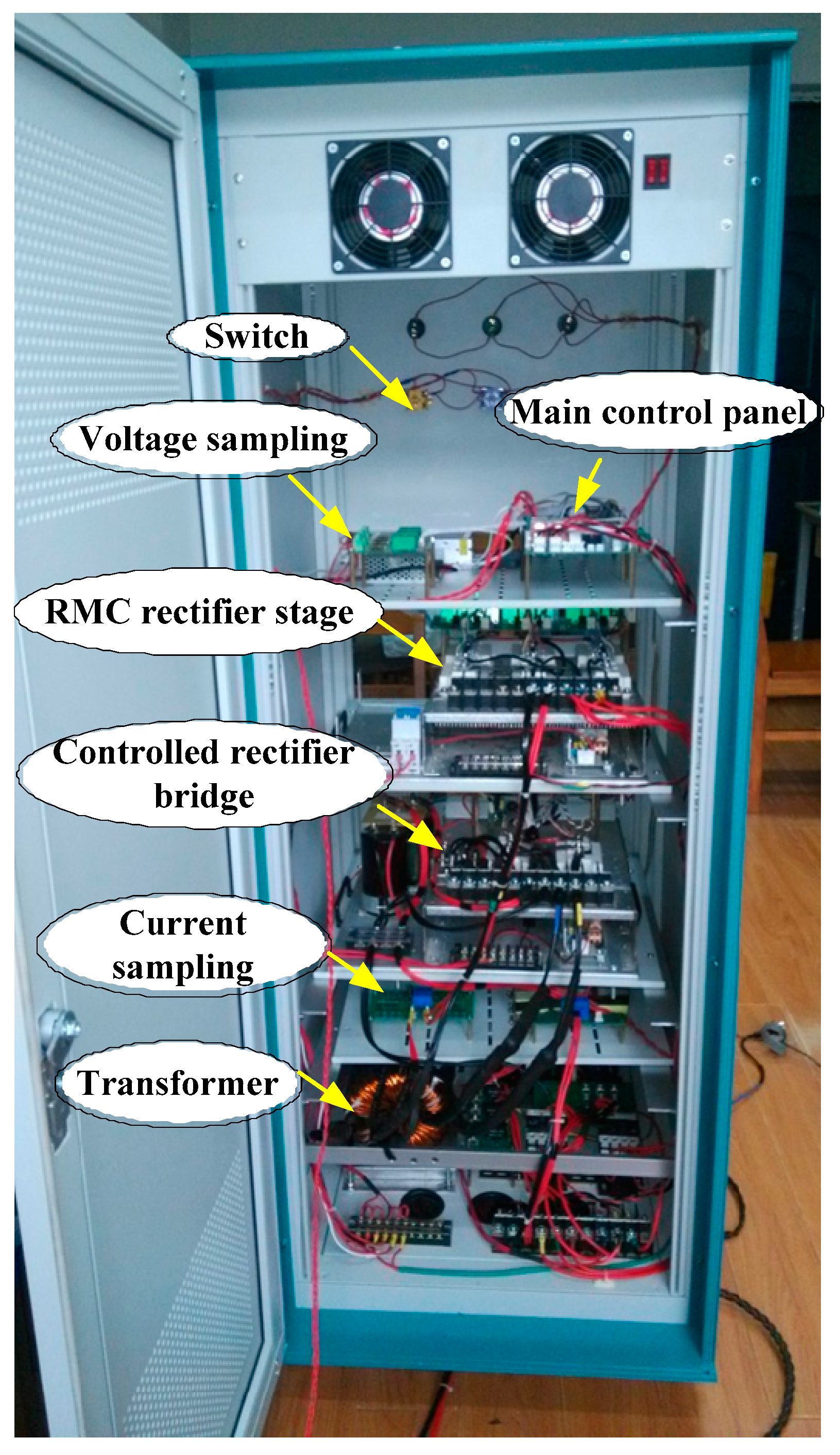
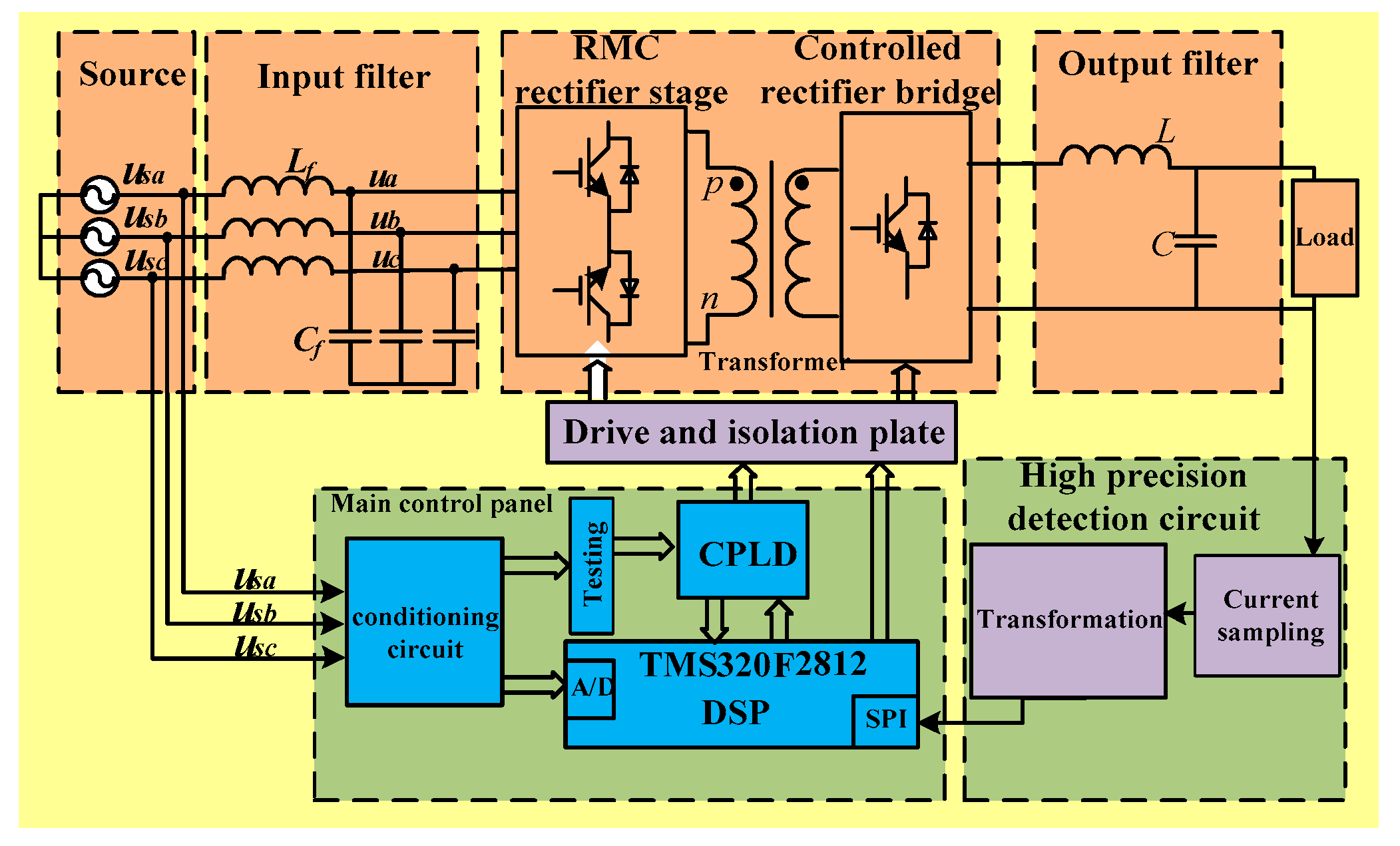
To verify the feasibility of the proposed strategy, a simulation was performed based using the MATLAB/Simulink environment, a BRMC experimental prototype was built as shown in Figure 15 and the block diagram of this experimental system is shown in Figure 16.

6. Simulation and Experimental Verification

The simulation and experimental parameters are shown in Table 4.

6.1. Validation of the New Commutation Strategy

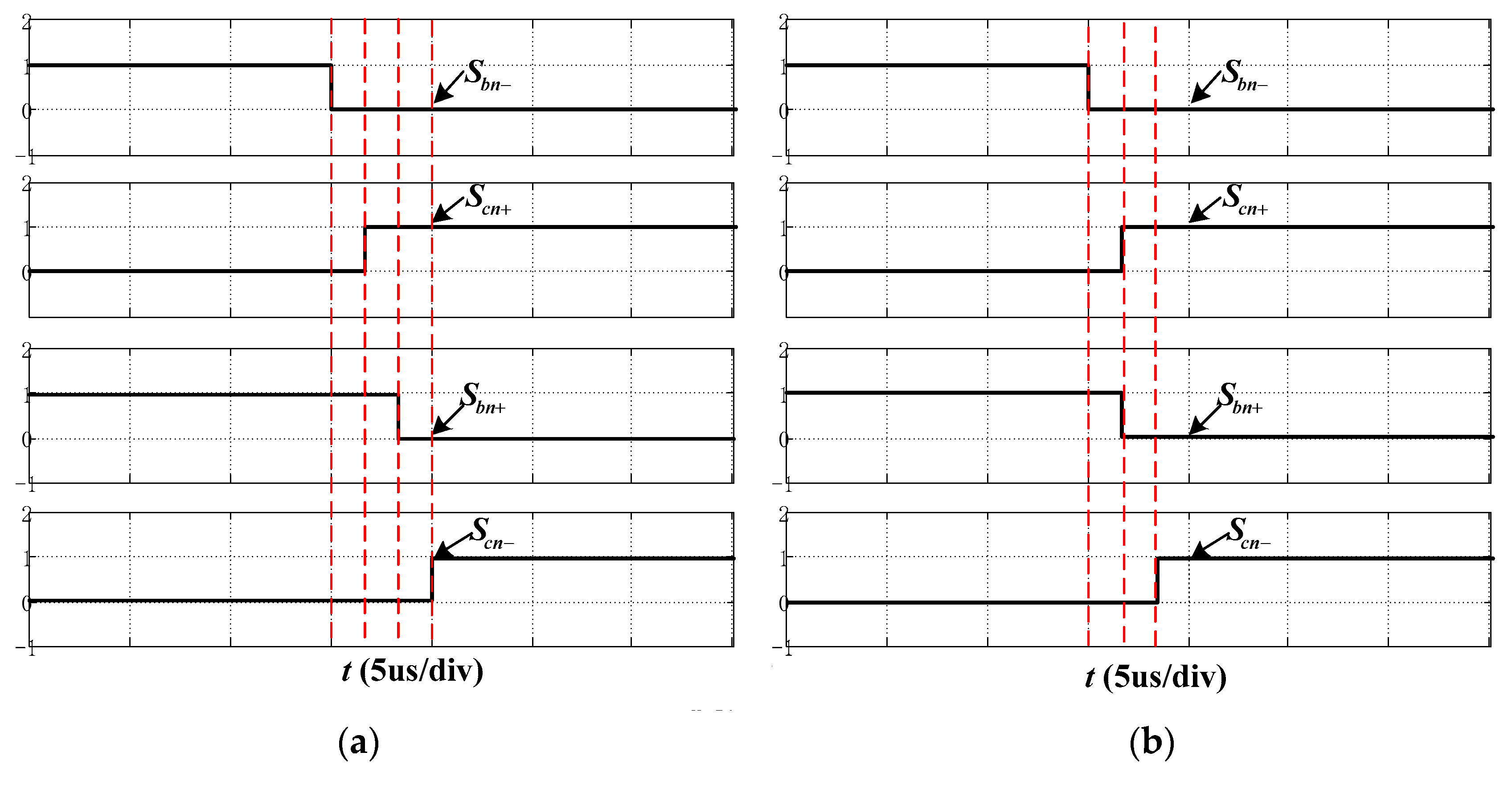
The interval time for each step commutation is set to 2 us according to the data manual of the used IGBT SK60GM123. The three-step commutation algorithm is the main commutation strategy, and the simulation and experimental results and analyses are shown as follows.
Figure 17 and Figure 18 show the simulation and experimental driving waveforms of the four-step commutation and the three-step commutation when Sbn switches to Scn in the positive half period. The experimental results are in agreement with the simulation results, therefore it can be found that the commutation interval is 2 us and the three-step commutation saves more time than the four-step commutation. Three-step commutation is used in the following simulation and experiments.
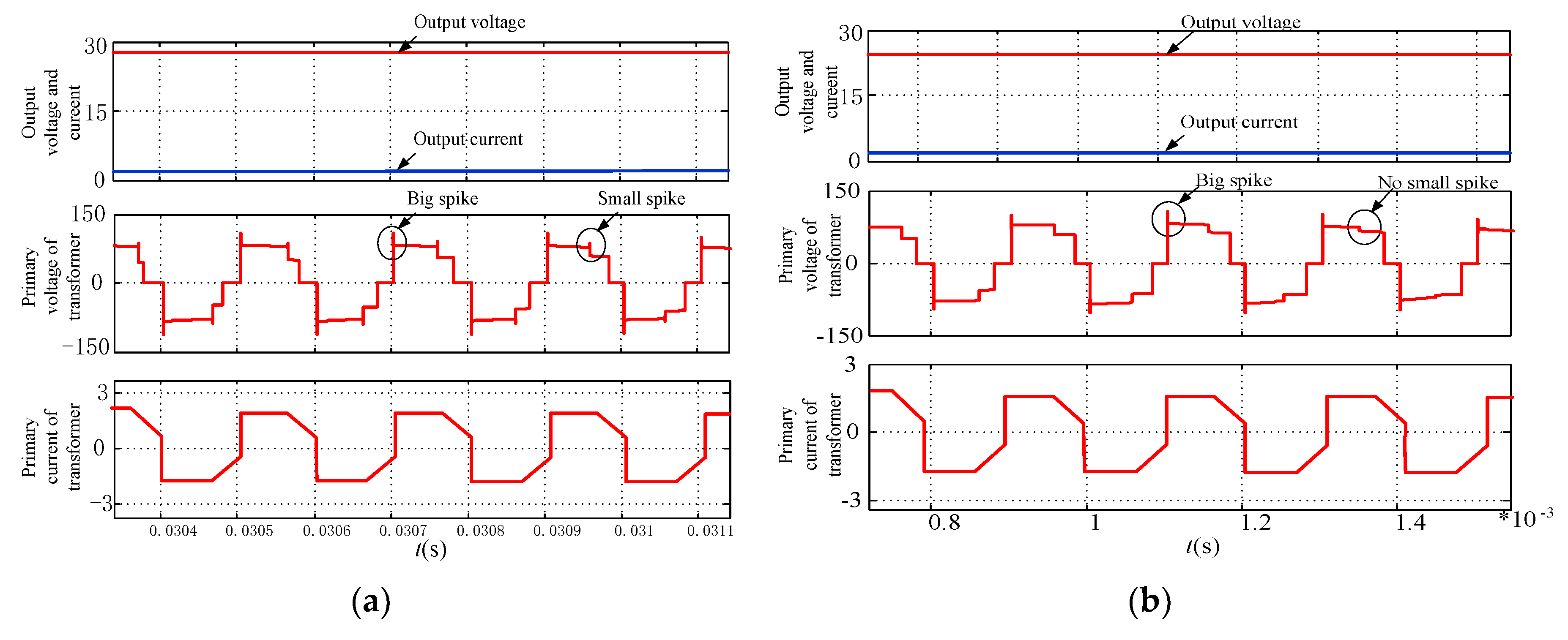
Figure 19 and Figure 20 show the simulation and experimental waveforms of the output voltage, current, primary voltage and current of the transformer. Comparing Figure 19b and Figure 20b with Figure 19a and Figure 20a, the results show that the big spike still exists and small spikes are eliminated as a result of vectors switching after using the three-step commutation. This proves that the three-step commutation can eliminate the small spike of the vector switchover.
At the positive and negative switching point, the current changes greatly, and the multi-step commutation algorithm cannot completely eliminate the voltage spike since the three-step commutation algorithm is semi-forced commutation. In order to eliminate this big spike by using the zero vectors commutation, the operating time of zero vector at positive and negative switch-over point is increased. It is the three-step commutation with zero vector mixed commutation strategy that first reduces the primary current of the transformer to zero and then uses three-step commutation.
Figure 21 and Figure 22 show the simulation and experimental waveform contrast before and after changing the action time of zero vectors. It can be found in Figure 21b and Figure 22b that the primary current of transformer has reduced to 0 relative to small action time of the zero vector shown in Figure 21a and Figure 22a when increasing action time of the zero vector. The safe commutation is realized when the positive and negative switching has no big spike.

6.2. Validation of Bidirectional Energy Flow

6.2.1. Energy Forward Mode

Figure 23 and Figure 24 show simulation and experimental waveforms of BRMC in energy forward mode at 5 kHz switching frequency. Seen from Figure 23a and Figure 24a, the input phase current is in phase with input voltage resulting in high power factor. It can be seen from Figure 23b and Figure 24b that the system gets a stable output voltage and current. At the same time, the polarity of voltage and current on the primary side of the transformer is consistent. This shows that energy is transmitted from the grid to the load. It’s convenient to observe the waveforms, the input current and output current in simulation is magnified 4 and 10 times respectively.
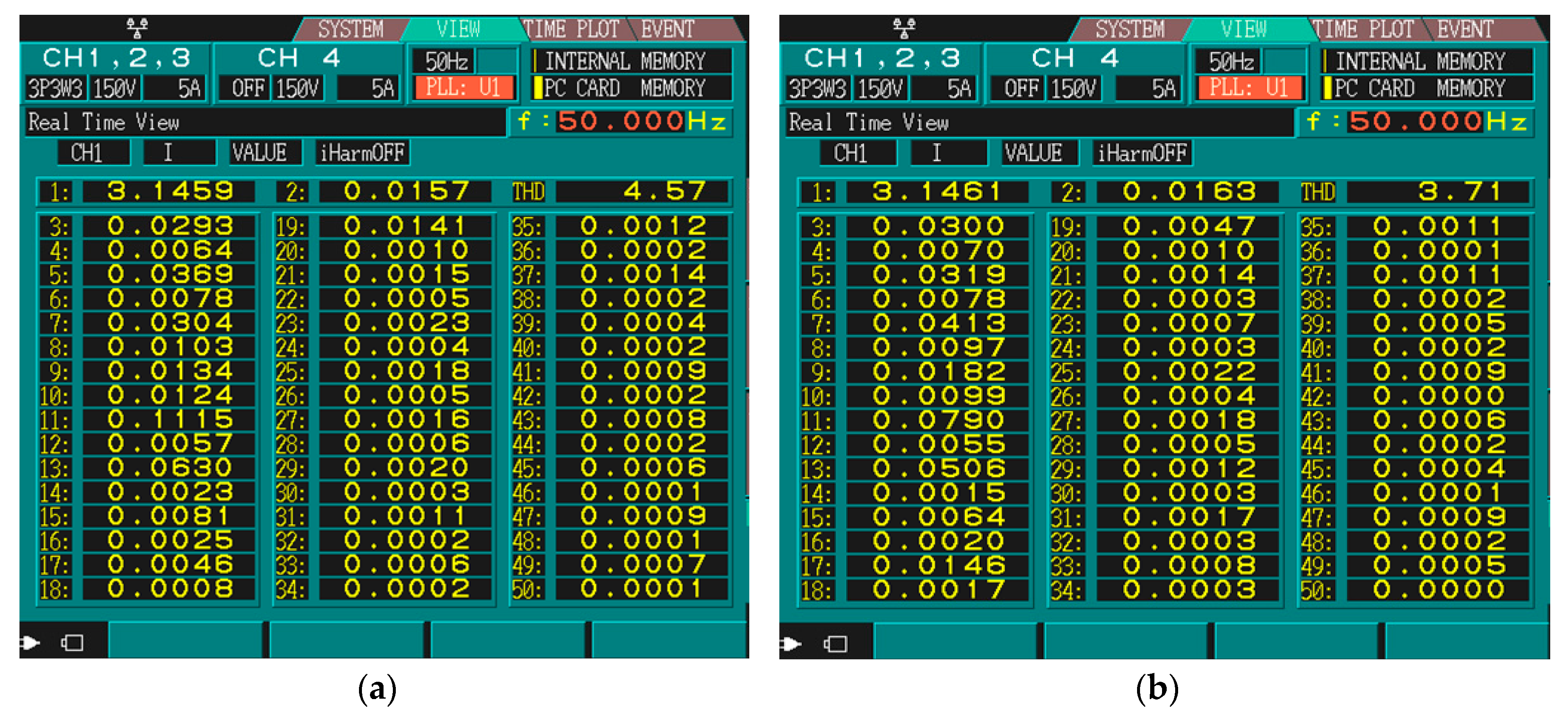
However, Figure 25 shows the harmonic magnitude of the input phase current at different switching frequency separately, obtained using a power analyzer. Figure 25a shows the input phase current THD at 4 kHz switching frequency and is 4.57%, which is higher than the THD at 5 kHz switching frequency. But this THD value is also lower than THD = 5% with the supply-side criterion in my country. The fifth harmonic, the eleventh harmonic, and the thirteenth harmonic of the input phase current are 0.0369, 0.1115, and 0.0630, respectively. Figure 25b shows the input phase current THD at 5 kHz switching frequency and is 3.71%. The fifth harmonic, the eleventh harmonic, and the thirteenth harmonic of the input phase current are 0.0319, 0.0790, and 0.0506, respectively.
Figure 26 shows a harmonic comparison using a relative value at different switching frequency. Comparing the fifth harmonic, the eleventh harmonic, and the thirteenth harmonic in the two conditions, it can be seen that the higher switching frequency enables the system to get a lower THD.

6.2.2. Energy Feedback Mode

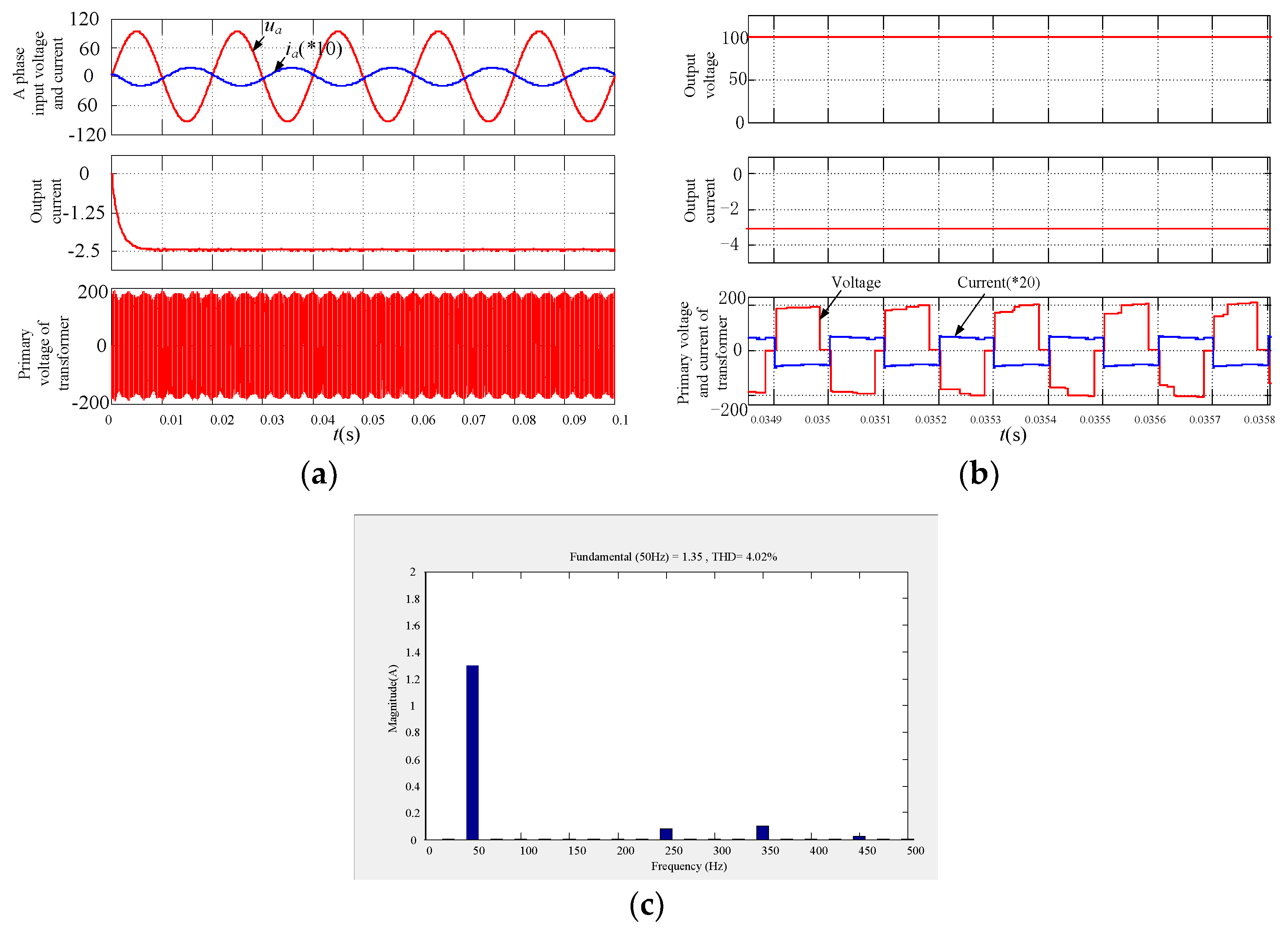
In general simulations, energy feedback modes can be easily realized. But in actual experiments, due to the limited experimental conditions, no larger inductances can meet the experimental requirements. In this paper, the method of a rectifier power series connection is used to simulate the energy in the accelerator, so as to verify the function of bidirectional BRMC energy feedback mode. The experimental verification is carried out with the input voltage of 100 V.
Figure 27 and Figure 28 show the simulation and experimental waveform in energy forward mode. Seen from Figure 27a and Figure 28a, the input phase voltage and current keep the same frequency and an 180° phase difference. It can be seen from Figure 27c and Figure 28c that the input current keeps its sinusoidal characteristics and the total harmonic is less than 5%. The system gets a good performance at the grid-side. Figure 27b and Figure 28b shows that the voltage on the load side stays positive and the current is negative. Meanwhile, the voltage and current of primary side of the transformer get the opposite polarity. The above conclusions show that the proposed method achieves the function of energy feedback.

6.3. Dynamic Experiment

Figure 29 shows the dynamic simulation and experimental waveforms of input voltage, current, output current and primary current of transform at a reference current jump from 1 A to 1.5 A. From the result, it can be seen that the output current can track the change of the reference with a jump from 1 A to 1.5 A, and the input current and primary current of transform also change with the jump of the reference. The input current is sinusoidal before and after the change of the output reference.

7. Conclusions

The contribution of this paper is to present a coordination control strategy based on bipolar current space vector modulation strategy and its hybrid commutation strategy for bidirectional reduced matrix-type exciting power supply in ion accelerator system. The expression of duty cycle of the BRMC rectifier stage is deduced and the schematic diagram of coordination control and the switch state table are given. An experimental prototype with DSP + CPLD controller as the control core is designed and built. The experimental results verify the effectiveness and feasibility of the coordinated control strategy and the new commutation strategy. The proposed scheme solves the problems of the large harmonic pollution of the power grid and the challenges recovering the energy of the ion accelerator, furthermore, safer commutation is achieved for industrial application. Thus, it can also be applied to charging piles, elevators and other places where bidirectional energy flow is needed.

Author Contributions

writing—original draft preparation and writing—review and editing, W.S and J.L; supervision, X.S.

Funding

This research was funded by National Natural Science Foundation of China (51877176). Shaanxi international exchange and cooperation project (2017KW-035). Shaanxi Provincial Education Department of Service Local Special Plan Project (18JC024). State Key Laboratory of Large Electric Drive System (SKLLDJ022016008). Research funding for Xi’an University of Technology (2016CX034).

Conflicts of Interest

The authors declare no conflict of interest.

References

  1. Furukawa, T.; Shirai, T.; Inaniwa, T.; Sato, S.; Takeshita, E.; Mizushima, K.; Hara, Y.; Noda, K.; Kakutani, N.; Kanai, Y.; et al. Development of Fast Scanning Magnets and Their Power Supply for Particle Therapy. IEEE Trans. Appl. Supercond. 2013, 24, 1–4. [Google Scholar] [CrossRef]
  2. Hays, S.; Pfeffer, H.; Claypool, B. Design Considerations of a Power Supply System for Fast Cycling Superconducting Accelerator Magnets of 2 Tesla B-Field Generated by a Conductor of 100kA Current. IEEE Trans. Appl.Supercond. 2008, 18, 1411–1414. [Google Scholar] [CrossRef]
  3. Zhang, G.; Dai, S.; Song, N.; Zhu, Z.; Zhang, J.; Guo, W.; Zhang, D.; Zhang, Z.; Xiao, L.; Lin, L. The Construction Progress of a High-Tc Superconducting Power Substation in China. IEEE Trans. Appl.Supercond. 2011, 21, 2824–2827. [Google Scholar] [CrossRef]
  4. Kumar, A.; Kumar Sadhu, P.; Kumar Mohanta, D.; Bharata Reddy, M. An Effective Switching Algorithm for Single Phase Matrix Converter in Induction Heating Applications. Electronics 2018, 7, 149. [Google Scholar] [CrossRef]
  5. Chen, Y.; Zhang, N.; Wang, K. A Series Resonant Filament Power Supply with Variable Structure and Oscillation-Free Switching Strategy for High-Voltage Accelerator Application. IEEE Trans. Power Electron. 2017, 32, 8229–8236. [Google Scholar] [CrossRef]
  6. Zhang, M.; Zhang, X.L.; Xia, L.L. Modeling and Analysis of Inverter-Type High Voltage Power Supply for NBI Accelerator Grid. IEEE Trans. Plasma. Sci. 2016, 44, 1716–1721. [Google Scholar] [CrossRef]
  7. Garcés, A.; Molinas, M. Reduced Matrix Converter Operated as Current Source for Off-Shore Wind Farms. In Proceedings of the 14th International Power Electronics and Motion Control Conference, Ohrid, Macedonia, 6–8 September 2010. [Google Scholar]
  8. Wang, C.; Liao, D.; Cai, H. Design and Research of DC Feedback Type of DC Electronic Load. Electr. Meas. Instrum. 2017, 54, 23–29. (In Chinese) [Google Scholar]
  9. Singh, A.K.; Jeyasankar, E.; Das, P.; Panda, S.K. A Single-Stage Matrix-Based Isolated Three-Phase AC–DC Converter with Novel Current Commutation. IEEE Trans. Transp. Electrif. 2017, 3, 814–830. [Google Scholar] [CrossRef]
  10. Wang, Y.; Ding, J.; Shi, L.; Gao, D. Devolopment of Power Supply for HIRFL-CSR Dipole Magnet. Atomic Energy Sci. Technol. 2015, 44, 90–92. (In Chinese) [Google Scholar]
  11. Burany, N. Safe Control of Four-quadrant Switches. In Proceedings of the IEEE Conference on the Industry Applications Society Annual Meeting, San Diego, CA, USA, 1–5 October 1989; pp. 1190–1194. [Google Scholar]
  12. Mahlein, J.; Igney, J.; Weigold, J. Matrix Converter Commutation Strategies with and without Explicit Input Voltage Sign Measurement. IEEE Trans. Ind. Electron. 2002, 49, 407–414. [Google Scholar] [CrossRef]
  13. Sayed, M.A.; Iqbal, A. Pluse Width Modulation Technique for A Three-to-Five Phase Matrix Converter with Reduced Commutations. IET Power Electron. 2015, 9, 466–475. [Google Scholar] [CrossRef]
  14. Hamouda, M.; Blanchette, H.F.; Al-Haddad, K. Indirect Matrix Converter’ Enhanced Commutation Method. IEEE Trans. Ind. Electron. 2015, 62, 671–679. [Google Scholar] [CrossRef]
  15. Singh, A.K.; Deshpande, P.P.; Panda, S.K. A Single-Stage Isolated Bidirectional Matrix Based AC-DC Converter for Energy Storage. In Proceedings of the IECON 2017-43rd Annual Conference of the IEEE Industrial Electronics Society, Beijing, China, 29 October–1 November 2017; pp. 2744–2749. [Google Scholar]
  16. Shi, T.; Wu, L.; Yan, Y.; Xia, C. Harmonic Spectrum of Output Voltage for Space Vector Pulse Width Modulated Ultra Sparse Matrix Converter. Energies 2018, 11, 390. [Google Scholar] [CrossRef]
  17. Guo, Z.; Zheng, C.; Zhao, L.; Qi, X. Control strategy study of Bi-directional energy storage converter. In Proceedings of the 12th IEEE Conference on Industrial Electronics and Applications (ICIEA), Siem Reap, Cambodia, 18–20 June 2017; pp. 567–571. [Google Scholar] [CrossRef]
  18. Kan, Z.; Li, P.; Yuan, R.; Zhang, C. Interleaved three-level bi-directional DC-DC converter and power flow control. In Proceedings of the 3rd International Conference on Intelligent Green Building and Smart Grid (IGBSG), Yi-Lan, Taiwan, 22–25 April2018; pp. 1–4. [Google Scholar] [CrossRef]
  19. Varajao, D.; Araujo, R.E.; Miranda, L.M. Modulation Strategy for a Single-Stage Bidirectional and Isolated AC-DC Matrix Converter for Energy Storage System. IEEE Trans. Ind. Electron. 2018, 65, 3458–3468. [Google Scholar] [CrossRef]
  20. Wheeler, P.W.; Clare, J.C.; Empringharn, L.; Bland, M.; Apap, M. Gate drive level intelligence and current sensing for matrix converter current commutation. IEEE Trans. Ind. Electron. 2002, 49, 382–389. [Google Scholar] [CrossRef]
  21. Guo, Y.; Guo, Y.; Deng, W.; Zhu, J.; Blaabjerg, F. An improved 4-step commutation method application for matrix converter. In Proceedings of the 17th International Conference on Electrical Machines and Systems (ICEMS), Hangzhou, China, 22–25 October 2014; pp. 3590–3593. [Google Scholar] [CrossRef]
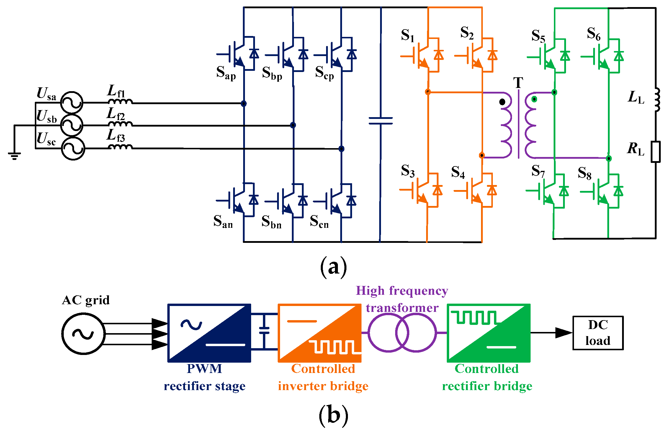
Figure 1. Conventional AC-DC converter:(a) Topology; (b) Schematic diagram.
Energies 11 03396 g001
Figure 2. Bidirectional reduced matrix converter:(a) Topology; (b) Schematic diagram.
Energies 11 03396 g002
Figure 3. Division of input voltage sectors.
Energies 11 03396 g003
Figure 4. Space vector diagram.
Energies 11 03396 g004
Figure 5. Operating mode of BRMC rectifier stage in the first sector (a) Mode of Uab; (b) Mode of Uac; (c) Mode of Uaa; (d) Mode of Uba; (e) Mode of Uca; (f) Mode of Uaa.
Energies 11 03396 g005
Figure 6. Sequence diagram of BRMC output voltage.
Energies 11 03396 g006
Figure 7. Principle waveforms of two different modes in the first sector.
Energies 11 03396 g007
Figure 8. Voltage and current of input and output(a) Energy forward mode; (b) Energy feedback mode.
Energies 11 03396 g008
Figure 9. Operating mode of BRMC in energy feedback mode: (a) Positive transformer primary voltage; (b) Negative transformer primary voltage.
Energies 11 03396 g009
Figure 10. The diagram of coordinated control strategy.
Energies 11 03396 g010
Figure 11. Commutation process: (a) Positive process; (b) Negative process.
Energies 11 03396 g011
Figure 12. Topology of commutation.
Energies 11 03396 g012
Figure 13. The switching logic diagram between input phase voltages.
Energies 11 03396 g013
Figure 14. Schematic diagram of the zero vector commutation: (a) Before the zero vector commutation; (b) After the zero vector commutation.
Energies 11 03396 g014
Figure 15. Experimental prototype.
Energies 11 03396 g015
Figure 16. The block diagram of BRMC magnet power supply system.
Energies 11 03396 g016
Figure 17. Commutation driving simulation diagram: (a) Four-step commutation; (b) Three-step commutation.
Energies 11 03396 g017
Figure 18. Commutation driving experiment diagram: (a) Four-step commutation; (b) Three-step commutation.
Energies 11 03396 g018
Figure 19. Simulation waveform contrast before and after the three-step commutation: (a) Before commutation; (b) After commutation.
Energies 11 03396 g019
Figure 20. Experimental waveform contrast before and after the three-step commutation: (a) Before commutation; (b) After commutation.
Energies 11 03396 g020
Figure 21. Simulation waveform contrasts of different zero vector: (a) Small zero vector; (b) Big zero vector.
Energies 11 03396 g021
Figure 22. Experimental waveform contrasts of different zero vector: (a) Small zero vector; (b) Big zero vector.
Energies 11 03396 g022
Figure 23. Simulation waveform of energy forward mode at 5 kHz switching frequency: (a) Input voltage and current (magnified 4 times); (b) Primary voltage and current (magnified 10 times) of transformer.
Energies 11 03396 g023
Figure 24. Experimental waveform of energy forward mode at 5 kHz switching frequency: (a) Input voltage and current; (b) Primary voltage and current of transformer.
Energies 11 03396 g024
Figure 25. Harmonic analysis of input current under different switching frequency: (a) 4 kHz switching frequency; (b) 5 kHz switching frequency.
Energies 11 03396 g025
Figure 26. Harmonic comparison in different frequency.
Energies 11 03396 g026
Figure 27. Simulation waveforms of energy feedback mode: (a) Input voltage and current (magnified 10 times); (b) Primary voltage and current of transformer; (c) Harmonic analysis of input current (magnified 20 times).
Energies 11 03396 g027
Figure 28. Experimental waveform of energy feedback mode: (a) Input voltage and current; (b) Primary voltage and current of transformer; (c) Harmonic analysis of input current.
Energies 11 03396 g028
Figure 29. Dynamic waveform of input voltage, current, output current and primary current of transform at a reference current jump from 1A to 1.5 A: (a) simulation waveform (input current is magnified 10 times); (b) experimental waveform.
Energies 11 03396 g029
Table 1. Comparisons of two topologies.
Comparison IndexPRB-DABBRMC
High-frequency transformerYesYes
Power densityNormalHigh
Converter stage32
EfficiencyNormalHigh
Lifetime NormalLong
Table 2. Duty cycle of each sector.
Sectorsdxdyd0
1 m s i s b m s i s c 1 m s i s a
2 m s i s a m s i s b 1 + m s i s c
3 m s i s c m s i s a 1 m s i s b
4 m s i s b m s i s c 1 + m s i s a
5 m s i s a m s i s b 1 m s i s c
6 m s i s c m s i s a 1 + m s i s b
Table 3. Modulation rule of the positive primary voltage of the transformer.
SectorNormally Opened SwitchSequential SwitchUPNSwitches of Controlled Rectifier Bridge
1Energy forwardSapSbn, Scn, Sanuab, uac, uaaS1, S4
Energy feedbackSanSbp, Scp, Sapuba, uca, uaaS2, S3
2Energy forwardScnSap, Sbp, Scpuac, ubc, uccS1, S4
Energy feedbackScpSan, Sbn, Scnuca, ucb, uccS2, S3
3Energy forwardSbpScn, San, Sbnubc, uba, ubbS1, S4
Energy feedbackSbnScp, Sap, Sbpucb, uab, ubbS2, S3
4Energy forwardSanSbp, Scp, Sapuba, uca, uaaS1, S4
Energy feedbackSapSbn, Scn, Sanuab, uac, uaaS2, S3
5Energy forwardScpSan, Sbn, Scnuca, ucb, uccS1, S4
Energy feedbackScnSap, Sbp, Scpuac, ubc, uccS2, S3
6Energy forwardSbnScp, Sap, Sbpucb, uab, ubbS1, S4
Energy feedbackSbpScn, San, Sbnubc, uba, ubbS2, S3
Table 4. Parameters.
ParametersValues
Input Voltage100 V/50 Hz
Input filter1.41 mH, 6 uF
Output filter10 mH, 450 uF
Switching frequency5 kHz
Load10 Ω, 10 mH