Coordination Control Method Suitable for Practical Engineering Applications for Distributed Power Flow Controller (DPFC)

Abstract
:1. Introduction
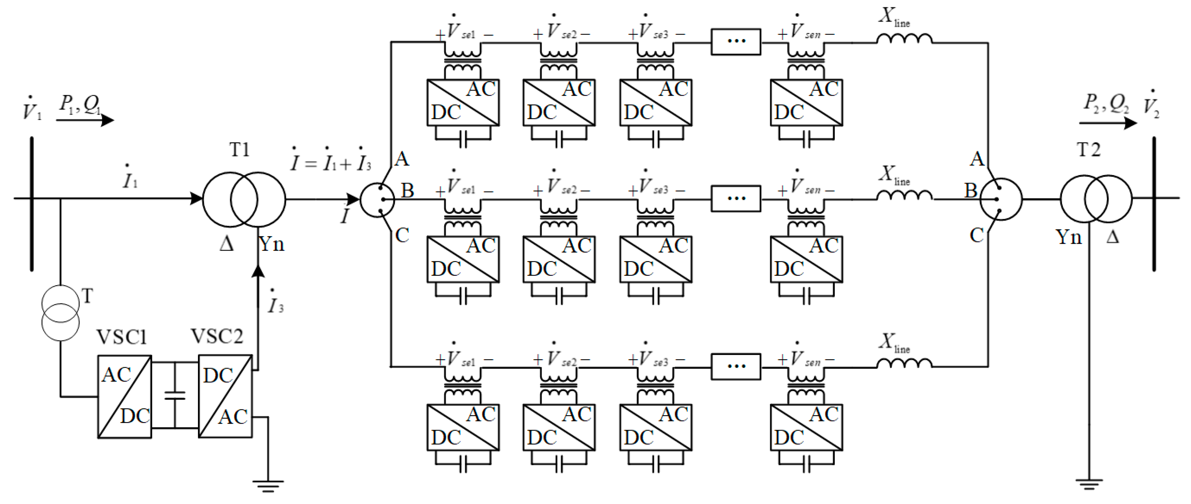
2. Basic Principle of the DPFC
3. Coordination Control System of a DPFC
3.1. The Computation of Reference Compensated Voltage
- Setting the number of DPFC series units to be n, the total base-frequency impedance between the sending-end and receiving-end of the power transmission system is , the short circuit reactance of each series unit is , and the initial current phasor of transmission line is
- Corresponding to the target power flow, and represent the RMS value of and phase angle that leads , respectively.where denotes the conjugate complex of the targeted current line .Supposing that the voltage phasors at the sending-end and receiving-end of the transmission system are unchanged during one control cycle, then we have
- The corresponding series-compensated voltage generated by each DPFC series unit is , where is the RMS value of the and is the phase angle that surpasses the voltage phasor . From the view of the total system, the effect of can be regarded as an equivalent series impedance injected by each series unit. Then, another expression of the transmission line isAccording to the obvious assumption and analysis, the series-compensated voltage is
- At the initial stable state t = t0, the phase angle that surpasses is , and all these measurements are saved in the upper-level controller.
- The RMS value and phase angle of the corresponding series-compensated voltage , and the phase angle are transferred to each series unit via a power line carrier communication link.
3.2. The Control Scheme of DPFC Series Units
3.2.1. The Single-Phase Locked Loop (SPLL)
3.2.2. The Reproduced Real-Time Phase for Reference Series-Compensated Voltage
3.2.3. The DC Capacitor Voltage Control
3.2.4. The Power Flow Control
4. The Simulation and Analysis of the DPFC Coordination Control System
4.1. Simulation of the DPFC Control System
4.1.1. Test Case 1
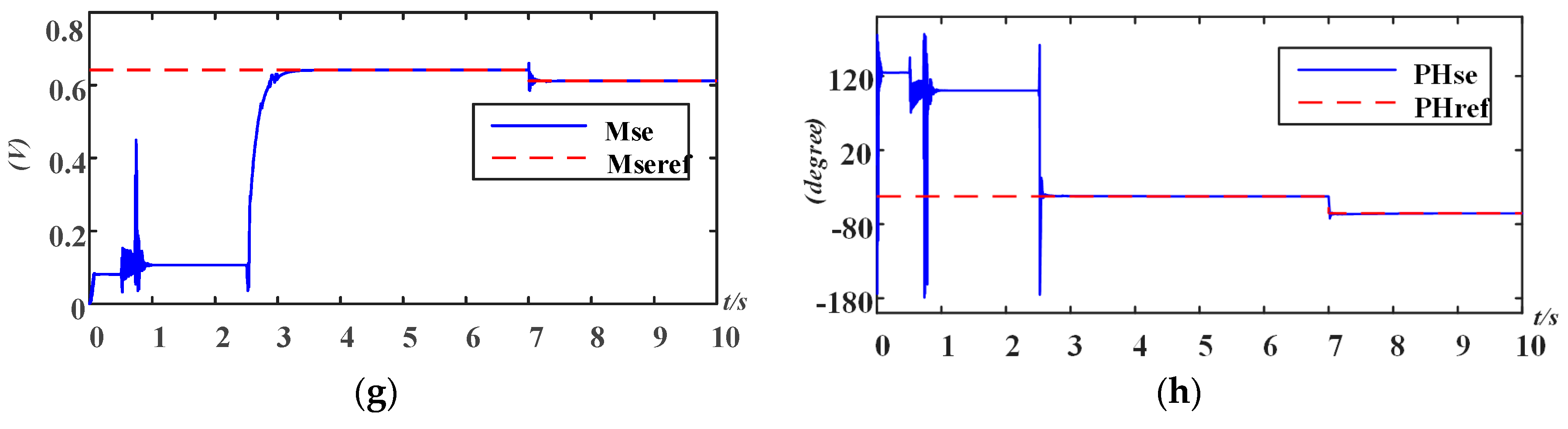
4.1.2. Test Case 2
4.2. Comparison of the Proposed Method with the State-of-the-Art
5. Conclusions
Author Contributions
Funding
Conflicts of Interest
References
- Hingorani, N.G. High power electronics and flexible ac transmission system. IEEE Power Eng. Rev. 1988, 50, 3–4. [Google Scholar] [CrossRef]
- Hingorani, N. Flexible AC Transmission. IEEE Spectr. 1993, 30, 40–45. [Google Scholar] [CrossRef]
- Hingorani, N.G.; Gyugyi, L. Understanding FACTS: Concepts and Technology of Flexible AC Transmission Systems; IEEE Press: New York, NY, USA, 2000. [Google Scholar]
- Gyugyi, L. Unified power-flow control concept for flexible AC transmission systems. IEE Proc. C-Gener. Transm. Distrib. 1992, 139, 323–331. [Google Scholar] [CrossRef]
- Gyugyi, L.; Schauder, C.; Williams, S.; Rietman, T.; Torgerson, D.; Edris, A. The unified power flow controller: A new approach to power transmission control. IEEE Trans. Power Deliv. 1995, 10, 1085–1097. [Google Scholar] [CrossRef]
- Li, P.; Wang, Y.; Feng, C.; Lin, J. Application of MMC-UPFC in the 500 kV power grid of Suzhou. J. Eng. 2017, 13, 2514–2518. [Google Scholar] [CrossRef]
- Albatsh, F.M.; Mekhilef, S.; Ahmad, S.; Mokhlis, H. Fuzzy-Logic-Based UPFC and Laboratory Prototype Validation for Dynamic Power Flow Control in Transmission Lines. IEEE Trans. Ind. Electron. 2017, 64, 9538–9548. [Google Scholar] [CrossRef]
- Pereira, M.; Zanetta, L.C. A current based model for load flow studies with UPFC. IEEE Trans. Power Syst. 2013, 28, 677–682. [Google Scholar] [CrossRef]
- Jena, M.K.; Samantaray, S.R. Data-Mining-Based Intelligent Differential Relaying for Transmission Lines Including UPFC and Wind Farms. IEEE Trans. Neural Netw. Learn. Syst. 2016, 27, 8–17. [Google Scholar] [CrossRef] [PubMed]
- Yuan, J.; Liu, L.; Fei, W.; Chen, L.; Chen, B.; Chen, B. Hybrid Electromagnetic Unified Power Flow Controller: A Novel Flexible and Effective Approach to Control Power Flow. IEEE Trans. Power Deliv. 2018, 33, 2061–2069. [Google Scholar] [CrossRef]
- Sayed, M.A.; Takeshita, T. Line Loss Minimization in Isolated Substations and Multiple Loop Distribution Systems Using the UPFC. IEEE Trans. Power Electron. 2014, 29, 5813–5822. [Google Scholar] [CrossRef]
- Divan, D.; Brumsickle, W.; Schneider, R.; Kranz, B.; Gascoigne, R.; Bradshaw, D.; Ingram, M.; Grant, I. A distributed static series compensator system for realizing active power flow control on existing power lines. In Proceedings of the IEEE PES Power Systems Conference and Exposition, New York, NY, USA, 10–13 October 2004; Volume 2, pp. 654–661. [Google Scholar]
- Divan, D.; Brumsickle, W.E.; Schneider, R.S.; Kranz, B.; Gascoigne, R.; Bradshaw, D.; Ingram, M.; Grant, I. A Distributed Static Series Compensator System for Realizing Active Power Flow Control on Existing Power Lines. IEEE Trans. Power Deliv. 2007, 22, 642–649. [Google Scholar] [CrossRef]
- Divan, D.; Johal, H. Distributed FACTS—A New Concept for Realizing Grid Power Flow Control. IEEE Trans. Power Electron. 2007, 22, 2253–2260. [Google Scholar] [CrossRef]
- Dorostkar-Ghamsari, M.; Fotuhi-Firuzabad, M. Probabilistic Worth Assessment of Distributed Static Series Compensators. IEEE Trans. Power Deliv. 2011, 26, 1734–1743. [Google Scholar] [CrossRef]
- Dorostkar-Ghamsari, M.; Fotuhi-Firuzabad, M. Optimal distributed static series compensator placement for enhancing power system loadability and reliability. IET Gener. Transm. Distrib. 2015, 9, 1043–1050. [Google Scholar] [CrossRef]
- Brissette, A.; Maksimović, D.; Levron, Y. Distributed Series Static Compensator Deployment Using a Linearized Transmission System Model. IEEE Trans. Power Deliv. 2015, 30, 1269–1277. [Google Scholar] [CrossRef]
- Raythaththa, K.G.; Vyas, B.Y. System parameters improvement of transmission line using Distributed Static Series Compensator (DSSC). In Proceedings of the International Conference on Energy Efficient Technologies for Sustainability (ICEETS), Nagercoil, India, 7–8 April 2016; pp. 459–463. [Google Scholar]
- Gaigowal, S.R.; Renge, M.M. Distributed power flow controller using single phase DSSC to realize active power flow control through transmission line. In Proceedings of the 2016 International Conference on Computation of Power Energy Information and Commuincation (ICCPEIC), Chennai, India, 20–21 April 2016; pp. 747–751. [Google Scholar]
- Yuan, Z.; de Haan, S.W.H.; Ferreira, J.B.; Cvoric, D. A FACTS Device: Distributed Power-Flow Controller (DPFC). IEEE Trans. Power Electron. 2010, 25, 2564–2572. [Google Scholar] [CrossRef]
- Yuan, Z.; de Haan, S.W.H.; Ferreira, J.B. Control scheme to improve DPFC performance during series converter failures. In Proceedings of the IEEE Power and Energy Society General Meeting, Providence, RI, USA, 25–29 July 2010; pp. 1–6. [Google Scholar]
- Yuan, Z.; de Haan, S.W.H.; Ferreira, J.B. Construction and first result of a scaled transmission system with the Distributed Power Flow Controller (DPFC). In Proceedings of the European Conference on Power Electronics and Applications, Barcelona, Spain, 8–10 September 2009; pp. 1–10. [Google Scholar]
- Divya, S.; Shyamala, U. Power Quality Improvement in Transmission Systems Using DPFC. In Proceedings of the IEEE 2nd International Conference on Electronics and Communication System (ICECS), Coimbatore, India, 26–27 February 2015. [Google Scholar]
- Jamshidi, A.; Barakati, S.M.; Ghahderijani, M.M. Power quality improvement and mitigation case study using distributed power flow controller. In Proceedings of the 2012 IEEE International Symposium on Industrial Electronics (ISIE), Hangzhou, China, 28–31 May 2012; pp. 464–468. [Google Scholar]
- Ramya, K.; Rajan, C.C.A. Analysis and Regulation of System Parameters Using DPFC. In Proceedings of the IEEE International Conference on Advances in Engineering, Science and Management (ICAESM), Nagapattinam, Tamil Nadu, India, 30–31 March 2012; pp. 505–509. [Google Scholar]
- Tang, Y.; Liu, Y.; Ning, J.; Zhao, J. Multi-Time Scale Coordinated Scheduling Strategy with Distributed Power Flow Controllers for Minimizing Wind Power Spillage. Energies 2017, 10, 1804. [Google Scholar] [CrossRef]
- Tang, A.; Shao, Y.; Huang, Y.; Xu, Q. A new topology of the distributed power flow controller and its electromagnetic transient characteristics. Electr. Power Syst. Res. 2018, 163, 280–287. [Google Scholar] [CrossRef]
- Tang, A.; Lu, J.; Xuan, J.; Yuan, W.; Wang, S. Study of the power control ability of the distributed power flow controller. Power Syst. Prot. Control 2012, 40, 15–20. [Google Scholar]
- Tang, A. Study on a new distributed power flow control method. Power Syst. Prot. Control 2011, 39, 89–94. [Google Scholar]
- Picardi, C.; Sgrò, D.; Gioffré, G. A simple and low-cost PLL structure for single-phase grid-connected inverters. In Proceedings of the 2010 International Symposium on Power Electronics Electrical Drives Automation and Motion (SPEEDAM), Pisa, Italy, 14–16 June 2010; pp. 358–362. [Google Scholar]


| Items | Parameter | |
|---|---|---|
| System fundamental frequency | 50 Hz | |
| Magnitude of third harmonic current | 6 A | |
| Number of series units | 10 | |
| Magnitude of and | 380 V | |
| Phase angle of voltage at sending-end δ | 8.92° | |
| Phase angle of voltage at receiving-end | 0° | |
| Transformer T1 | 380 V/380 V, 1 kVA, 0.1 p.u, ∆-YN | |
| Transformer T2 | 380 V/380 V, 1 kVA, 0.1 p.u, YN-∆ | |
| Single-turn transformer of series unit | 20 V/100 V, 0.5 kVA, 0.1 p.u | |
| Reference value of DC capacitor voltage | 20 V | |
| Value of DC capacitor of VSC in series unit | 2200 μF | |
| LC filter of VSC in series unit | 1.33 mH, 100 μF | |
| Switch frequency of Insulated-gate bipolar transistor (IGBT) | 2100 Hz | |
| Zline | Rline = 0.279 Ω, Lline = 0.0127 H | |
| Initial phase angle φ | 5.03° | |
| Starting time for the breaker of series unit | 0.5 s | |
| Starting time for the power flow control | 2.5 s | |
| Targeted power flow | t = 2.5–5.0 s | Pset1 = 800 W, Qset1 = −100 Var |
| t = 5.0–10.0 s | Pset2 = 1000 W, Qset2 = −100 Var | |
| Fcn1 | Fcn2 | Fcn3 | Fcn4 |
| = 5 | = 5 | = 10 | G = 0.1 |
| = 5 × 10^−5 s | = 5 × 10^−5 s | = 0.2 s | T = 0.02 s |
| Fcn5 | Fcn6 | Fcn7 | Fcn8 |
| = 10 | G1 = 0.2 | = 0.95 | G2 = 1 |
| = 0.005 s | T1 = 0.02 s | = 0.5 s | T2 = 0.02 s |
© 2018 by the authors. Licensee MDPI, Basel, Switzerland. This article is an open access article distributed under the terms and conditions of the Creative Commons Attribution (CC BY) license (http://creativecommons.org/licenses/by/4.0/).
Share and Cite
Xiao, M.; Wang, S. Coordination Control Method Suitable for Practical Engineering Applications for Distributed Power Flow Controller (DPFC). Energies 2018, 11, 3406. https://doi.org/10.3390/en11123406
Xiao M, Wang S. Coordination Control Method Suitable for Practical Engineering Applications for Distributed Power Flow Controller (DPFC). Energies. 2018; 11(12):3406. https://doi.org/10.3390/en11123406
Chicago/Turabian StyleXiao, Mengmeng, and Shaorong Wang. 2018. "Coordination Control Method Suitable for Practical Engineering Applications for Distributed Power Flow Controller (DPFC)" Energies 11, no. 12: 3406. https://doi.org/10.3390/en11123406