1. Introduction
Lithium-ion batteries are favored by the electric vehicle market because of their high energy density, long cycle life, and the fact that they have no memory effect [
1,
2]. The nominal voltage of single cell is between 3.2 V and 3.7 V. A large number of lithium-ion batteries need to be connected in series to meet the voltage requirements [
3,
4,
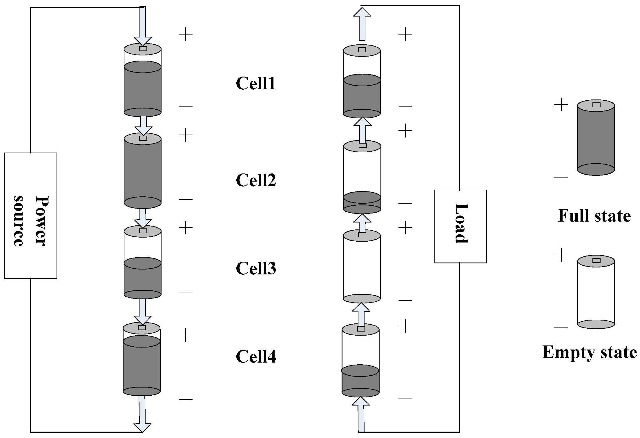
5]. However, due to differences in the working environment and the performance of each single cell, their energy is inconsistent, as shown in
Figure 1. In the charging process, the single cell with the highest energy becomes full first, and in the discharging process, the single cell with the lowest energy is emptied first. With the increase of charging and discharging times, the charging and discharging capacity of the battery pack will get smaller and smaller. In addition, over-charging and over-discharging are not allowed in each single cell to prevent battery life reduction, however, this creates a risk of explosion when the single cell is over-charged [
4]. Therefore, effective balance measures must be taken to solve the problem of energy inconsistencies between single cells and to prolong the life and improve the charging and discharging capacity of the battery pack.
The existing balance methods can be divided into energy consumption balance and the non-energy consumption balance methods. The energy consumption balance method is simpler, but it depends on energy consumption to achieve balance. The non-energy consumption balance includes the inductance balance [
2,
3,
4,
5,
6,
7,
8,
9,
10], the capacitance balance [
11], the inductance-capacitance balance [
12,
13,
14], and the transformer balance [
15,
16]. The battery pack has three different working states, including the charging state, the discharging state and the static state. Each working state has its own characteristics, and a balance method may not be suitable for the three different working states simultaneously. The existing balance methods focus more on how to achieve the balanced result, while the different working states of the battery and the rapidity and security of the balance for the different working states are often ignored.
In this paper, an energy equalizer for lithium-ion batteries is studied in terms of the balanced speed, the controllability of the balanced energy, the realization of the balance circuit, and the security of the balanced system. According to each working state of the battery, different balancing strategies are developed to realize a multi-mode energy equalizer that is suitable for each working state of the battery simultaneously. The equalizer suggested by this paper can rapidly control the energy rising rate of the strongest single cell in the charging state, and can rapidly control the energy declining rate of the weakest single cell in the discharging state.
2. Balance Strategy
2.1. Relationship between Balanced Control Object and Battery Working State
The strongest/weakest single cell limits the charging/discharging capacity of the battery pack in the battery charging/discharging state. The strongest single cell or the weakest single cell was selected as the balanced control object under the same charging current and stop charging conditions, and the state of charge (
SOC) curves of three lithium-ion battery cells are shown in
Figure 2. Compared with
Figure 2b, the charging time in
Figure 2a is extended by
t12, that is, the charging capacity of the battery pack increased when the strongest cell was selected as the balanced control object. The charging capacity of the battery pack represents its ability to absorb energy; the more energy it can absorb, the stronger the charging capacity.
The strongest single cell or the weakest single cell was selected as the balanced control object under the same discharging current and stop discharging conditions, and the
SOC curves of three lithium-ion battery cells are shown in
Figure 3. Compared with
Figure 3a, the discharging time of
Figure 3b was extended by
t12, that is, the discharging capacity of the battery pack increased when the weakest cell was selected as the balanced control object. The discharging capacity of the battery pack represents its ability to release energy; the more energy that can be released, the stronger the discharging capacity.
Assuming that a battery pack is composed of
n single battery cells in a series, and its initial
SOC value, maximum
SOC value, and minimum
SOC value are respectively represented as
,
, and
, their expressions can be represented by the following equations:
The average balance current is
Ib and the balance time is
, assuming that the
SOC value of Cell-x/Cell-y is still the maximum/minimum at the end of the balance. When the
SOC value of the battery pack reaches
SOCA/
SOCB, the charging/discharging ends. When no balance measures are taken, the charging/discharging capacity of the battery pack can be expressed by the following equations
where
C is the rated capacity of a single battery cell.
When the balance measure in
Figure 2a/
Figure 3b is adopted, the charging/discharging capacity of the battery pack can be expressed by the following equations:
Obviously,
is bigger than
, and
is bigger than
.
2.2. Energy Transfer Forms
The balanced energy should be transmitted continuously throughout the balanced period, T. Continuous balanced energy is conducive to the fast and effective transfer of energy, thus rapidly improving the charging and discharging capacity of the battery pack and the balanced speed. As shown in
Figure 4b, if energy (E) transferred under the energy discontinuous mode is equal to the energy transferred under the continuous mode at the same time (T), the amount of energy transferred should be increased in the energy intermittent mode. In other words, the current value is increased. Although the energy discontinuous mode can achieve the same balanced result in continuous mode by increasing the current value, a larger current will increase the burden of the balance circuit, the capacity of the corresponding switch device, and the security problem of the equalizer will be introduced. Therefore, continuous balanced energy is more conducive to the realization of balance.
2.3. Balance Strategies
In order to improve the charging/discharging capacity and the balanced speed of the battery pack quickly and effectively, the balance strategies were studied from the controlled object and the energy transfer forms under the different working states of the battery in this paper. In the battery charging state, the strongest battery cell was selected as the balanced control object to be discharged. Conversely, in the battery discharging state, the weakest battery cell was selected as the balanced control object to be charged, while in the battery static state, the strongest or the weakest battery cell was selected as the balanced control object to be discharged or charged. In all working states of the battery, the balanced energy was continuous and controllable.
3. The Circuit Topology and Principle of the Equalizer
3.1. Circuit Topology of the Equalizer
Based on the above balance strategies, the circuit topology of the equalizer was constructed in this paper as shown in
Figure 5. The circuit topology of the equalizer is composed of a bidirectional power switch matrix and a balanced main circuit. The bidirectional power switch matrix consist of 2*n bidirectional switch units, namely k11 to k1n and k21 to k2n, which can be controllable bidirectional switches or relays. The balanced main circuit consists of an inductor (L), two master control switches, M1 and M2, and a voltage source (E) that it is obtained from the battery pack through a DC/DC convertor and was adjustable. When the two master control switches are controlled by the pulse-width modulation (PWM) signal separately, the balanced main circuit is equivalent to two completely different chopper circuits. Regardless of the type of chopper circuit, the inductor L is always in the same loop as the controlled object in balance thus the balanced energy of the controlled object can be continuous. Therefore, the balance-controlled object is selected by the bidirectional power switch matrix, and the continuous controllable bidirectional balanced energy is realized by the balanced main circuit.
3.2. Principle of Balance
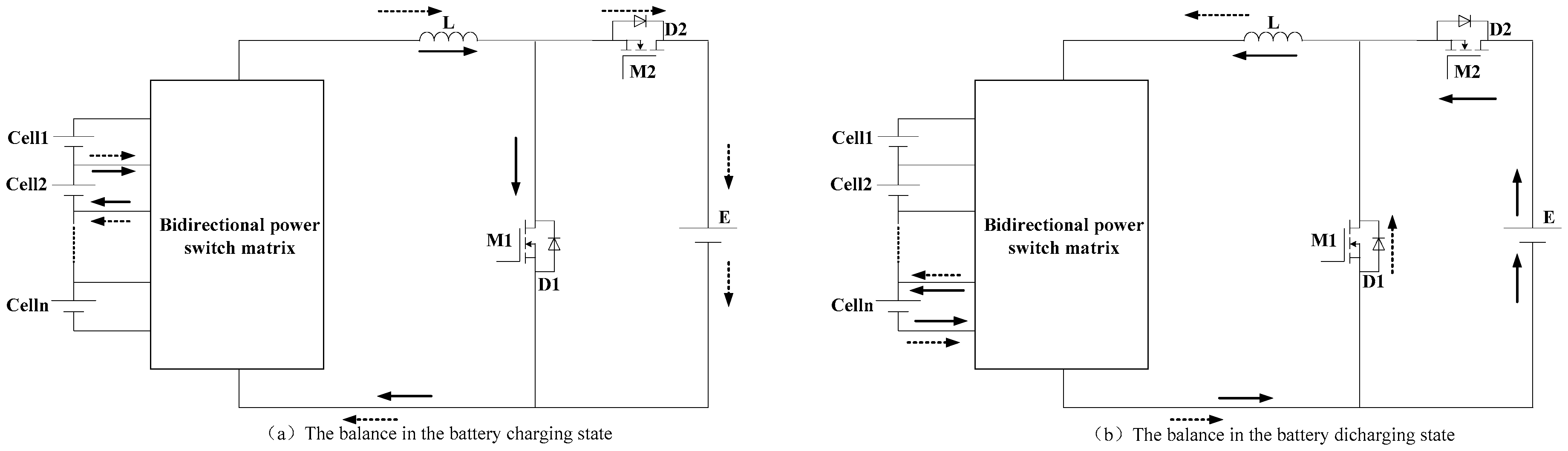
In the battery charging state, the strongest battery cell or several adjacent cells of a battery pack are selected as the balanced control object through the switch matrix, meanwhile the PWM signal is performed on the master control switch M1, then the balanced energy is transferred from the control object to the voltage source E. As shown in
Figure 6a, when the M1 is turned on, the energy of the control object is transferred to the inductor L and the energy flow direction is shown by the solid line arrow. When the M1 is turned off, the energy stored in the L is transferred to the voltage source E via the antiparallel diode D2 of the M2, and the energy flow direction is shown by the dotted line arrow.
In the battery discharging state, the weakest battery cell or several adjacent cells of a battery pack are selected as the balanced control object through the switch matrix, meanwhile, the PWM signal is performed on the master control switch M2, then the balanced energy is transferred from the voltage source E to the control object. As shown in
Figure 6b, when the M2 is turned on, the energy flow direction is shown by the solid line arrow. When the M2 is turned off, the energy stored in the L is transferred to the control object via the antiparallel diode D1 of the M1, and the energy flow direction is shown by the dotted line arrow.
In the battery static state, there are two kinds of balance strategies that can be adopted, and the strongest battery cell/s is/are balanced to be discharged as shown in
Figure 6a, or the weakest battery cell/s is/are balanced to be charged as shown in
Figure 6b. However, in order to improve the charging and discharging capacity of the battery pack, the former strategy is adopted in the battery static state that happens before the battery charging, and the latter strategy is adopted in the battery static that happens before or during the battery discharging.
3.3. Characteristics of the Equalizer
First, the working state of the battery is considered by the equalizer, and the different balance strategies are proposed for the three working states of the battery. Second, the control object is selected according to the principle of decreasing the energy changing rate of the balanced battery, which can not only effectively improve the charging and discharging capacity of the battery pack, but is also conducive to using the battery healthily. Third, the continuous balanced energy is realized, that is, the balanced energy emitted and absorbed by the balanced battery is always continuous. Therefore, a new topology circuit for a multi-mode energy equalizer was constructed for this paper. The above three points are also the characteristics of the equalizer proposed in this paper that are different from existing equalizers.
As shown in
Figure 5, when the PWM signal is applied to M1, the continuous energy is transferred from the balanced battery on the left to the voltage source E on the right, and when the PWM signal is applied to M2, the continuous energy is transferred from the voltage source to the balanced battery on the left. In the battery charging state, the strongest battery cell or several adjacent cells of a battery pack is/are selected to be discharged, and in the battery discharging state, the weakest battery cell or several adjacent cells of a battery pack is/are selected to be charged. In the battery static state, the strongest or weakest battery cell/s of a battery pack is/are selected to be discharged/charged.
4. Balance Experiment
4.1. Experimental Platform
In this paper, the balance experiments carried out under the three battery working states were carried out for a battery pack composed of four serially connected lithium iron phosphate battery cells. The rated voltage of the battery cell was 3.2 V, and the rated capacity was 21 Ah. The battery was charged or discharged through the charging/discharging instrument in the laboratory, as shown in
Figure 7, in addition, the experimental platform also included the batteries, equalizer, voltage source, current sensor, and the oscilloscope, and the laboratory temperature was about 25 °C. Among them, the master control switches of the equalizer were MOSFETs with a low on-resistance of IRF3205, and the internal resistance of the master switch was 8 mΩ. The charging/discharging current was 10 A, which was provided by the charging/discharging instrument. The charging balance experiment was stopped until the
SOC value of the battery pack reached 70%, and the discharging experiment was stopped until the
SOC value of the battery pack dropped to 10%.
4.2. Balance Experiments in the Battery Static and the Charging State
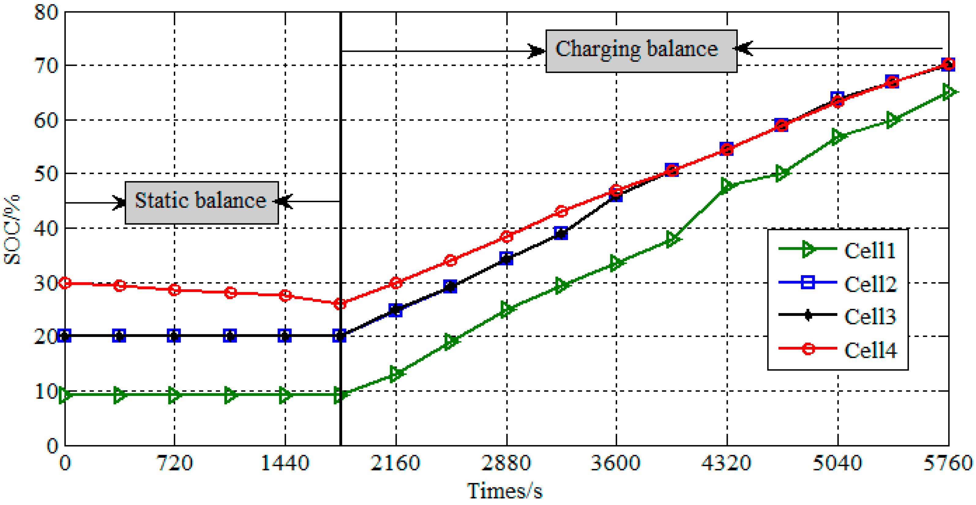
The initial
SOC values of Cell1, Cell2, Cell3 and Cell4 were 9.3%, 20%, 20%, and 30%, respectively, and the switching frequency of the switch M1 was 20 kHz. The balance experiment in the battery static state was carried out first, and the static time was 1800 s. In the static balance, the battery Cell4 was selected as the control object to be discharged, the duty ratio of the switch M1 was 58.85%, and the average balanced current was about 2.09 A. The balanced current waveform of the battery Cell4 and the PWM waveform of the switch M1 are shown in
Figure 8.
After the static balance, the balance experiment in the battery charging state was carried out, and the charging current was 10 A. In the charging balance, the battery Cell4 was selected to be balanced and the average balanced current was about 2.02 A. The balanced current waveform and the PWM waveform are shown in
Figure 9.
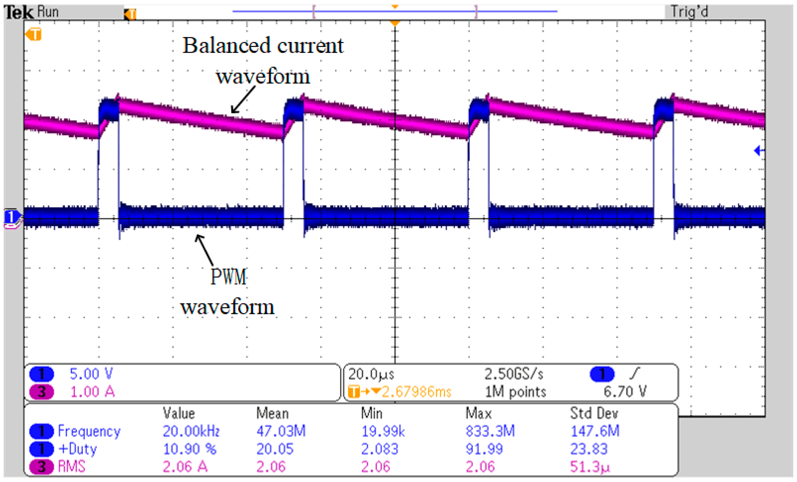
After 1800 s, the batteries Cell2, Cell3 and Cell4 had the same energy, so the three cells were selected as the balanced control object to discharge, the duty ratio of the switch M1 was 10.9%, and the average balanced current was about 2.06 A. The balanced current waveform of the control object and the PWM waveform of the switch M1 are shown in
Figure 10. The balanced experiment was stopped until the
SOC value of the battery pack reached 70%, the balanced time was 5760 s, and the
SOC values of each battery cell were 65%, 70%, 70%, and 70.2%, respectively, at the end of the balanced experiment. The
SOC curves during the experiment of the static and the charging state are shown in
Figure 11.
4.3. Balance Experiments in the Battery Static and Discharging State
After the charging experiment, the static balance experiment of 1800 s was carried out. During the experiment, the weakest battery Cell1 was balanced and the average current was about 2 A. The balanced charging current waveform of the battery Cell1 and the PWM waveform of the switch M2 are shown in
Figure 12.
The
SOC values of each battery cell were 70%, 70%, 70%, and 70.2%, respectively, at the end of the static balanced experiment, and the
SOC values of the four battery cells became more consistent. The discharging experiment without the balance was then carried out until the SOC value of the battery pack dropped to 10%, and the discharging current in the experiment was a constant current of 10 A. The experiment time was 6120 s, the
SOC values of each battery cell were 9.5%, 9.5%, 9.5%, and 9.7%, respectively, at the end of the experiment, and the
SOC curves are shown in
Figure 13.
5. Analysis of the Experimental Results
In this paper, the different balanced strategies are adopted respectively under the three different working states of the battery, the strongest battery cell/s is/are the control object to be discharged in the battery charging state, and the weakest battery cell/s is/are the control object to be charged in the battery discharging state. Therefore, the charging/discharging capacity of the battery pack will be effectively and quickly improved, which will also increase the balance speed of the equalizer. The balance current is continuous and controllable, as shown in
Figure 8,
Figure 9,
Figure 10 and
Figure 12. The balance energy of the balanced control object can be transferred stably and continuously, therefore, the security of the equalizer is higher and the balanced speed will be faster.
The results of the charging balance experiment, the discharging balance experiment, and the static balance experiment were set out in this paper. The initial SOC values of the four serially-connected battery cells were 9.3%, 20%, 20%, and 30%, respectively, and the SOC values were changed to 9.5%, 9.5%, 9.5%, and 9.7%, respectively, after the balance experiments in this paper. The average value of the balanced current from the balance experiments was about 2 A, and the maximum energy difference between single battery cells was reduced from 20.7% to 0.2% after one charging/discharging cycle balance experiment and a static balance experiment of 3600 s. In practice, both the number of single battery cells in the series and the degree of energy inconsistency between them will affect the balance speed and the balance time. If the number of single battery cells is larger and the degree of the energy inconsistency between them is more serious, multiple balanced charging/discharging cycles will be needed to make the energy between single battery cells consistent. In addition, the value of the balance current can be adjusted according to the degree of energy inconsistency between battery cells, and the higher the balance current value, the faster the balance speed, or the fewer cycles of balanced charging/discharging will be needed.
6. Conclusions
The energy balance strategies were studied in terms of the balanced control object and the balanced energy transferred forms based on three different working states of the battery in this paper. In order to improve the charging and discharging capacity of the battery pack and increase the balance speed, the following requirements were set for the equalizer: First, the balance energy should be continuous and controllable; second, the strongest battery cell or cells of the battery pack were selected as the control object to be balanced in the battery charging state, and the weakest battery cell or cells were selected as the control object to be balanced in the battery discharging state. This study described in this paper constructed an equalizer and topology circuit satisfying the above requirements, built a balance experiment platform, and completed the balance experiments. Different balance strategies were proposed for the three working states of the battery, and the balance energy was continuous and controllable, resulting in a fast balance speed. In addition, as the balance energy was continuous and stable and the energy changing rate of the balanced battery always decreased, even a larger balance current will not affect the service life of the battery.
Author Contributions
H.L. proposed the main idea of this paper. C.D. and S.C. completed the paper writing. B.L., Y.G., and S.L. set up the experimental platform and completed the balanced experiments of the paper.
Funding
This research received no external funding.
Acknowledgments
The research is supported in part by National Science Foundation of China (Grant Nos. 51707088 and 51607081).
Conflicts of Interest
The authors declare no conflicts of interest.
References
- Liu, W.; Wu, H.S.; He, Z.C.; Yang, G. A multistage current charging method for li-ion battery considering balance of internal consumption and charging speed. Trans. China Electrotech. Soc. 2017, 32, 112–120. [Google Scholar]
- Liu, H.R.; Xia, C.Y. An investigation into a new battery balancing solution for electric vehicles. Automot. Eng. 2013, 35, 934–938. [Google Scholar]
- Li, W.; Kang, L.; Guo, X.; Yao, Y. Multi-objective predictive balancing control of battery packs based on predictive current. Energies 2016, 9, 298. [Google Scholar] [CrossRef]
- Hua, C.C.; Fang, Y.H.; Huang, J.F. Inductor based equalizer with a chain structure of switched capacitor to improve balancing speed. In Proceedings of the 2015 18th International Conference on Electrical Machines and Systems (ICEMS), Pattaya, Thailand, 25–28 October 2015; pp. 2151–2154. [Google Scholar]
- Gao, Z.; Chin, C.S.; Chiew, J.H.K.; Jia, J.; Zhang, C. Design and implementation of a smart lithium-ion battery system with real-time fault diagnosis capability for electric vehicles. Energies 2017, 10, 1503. [Google Scholar] [CrossRef]
- Zheng, Z.; Wang, K.; Xu, L.; Li, Y. A hybrid cascaded multilevel converter for battery energy management applied in electric vehicles. IEEE Trans. Power Electron. 2014, 29, 3537–3546. [Google Scholar] [CrossRef]
- Liu, H.R.; Li, Y.Z.; Chen, S.L.; Shuai, C.Y. Lithium-ion battery charging and discharging equalizer and balancing strategies. Acta Electron. Since 2016, 44, 1981–1987. [Google Scholar]
- Xia, J. Design of balance protection and hardware of BMS based on LTC6802. J. Tianjin Univ. Technol. 2016, 32, 20–33. [Google Scholar]
- Han, J.F.; Long, Z.Y.; Guo, Y.F.; Pan, S.H.; Yang, C. Research of charging equalization circuit and equilibrium strategy for Li-ion battery series. Chin. J. Power Sources 2016, 40, 2439–2443. [Google Scholar]
- Gao, Z.C.; Chin, C.S.; Ton, W.D.; Chiew, J.; Jia, J. State-of-charge estimation and active cell pack balancing design of lithium battery power system for smart electric vehicle. J. Adv. Transp. 2017, 2017, 6510747. [Google Scholar] [CrossRef]
- Daowd, M.; Antoine, M.; Omar, N.; Van den Bossche, P.; Van Mierlo, J. Single Switched Capacitor Battery Balancing System Enhancements. Energies 2013, 6, 2149–2179. [Google Scholar] [CrossRef]
- Shang, Y.; Zhang, C.; Cui, N.; Guerrero, J.M.; Sun, K. A crossed pack-to-cell equalizer based on quasi-resonant LC converter with adaptive fuzzy logic equalization control for series-connected lithium-ion battery strings. In Proceedings of the 2015 IEEE Applied Power Electronics Conference and Exposition (APEC), Charlotte, NC, USA, 15–19 March 2015; pp. 1685–1692. [Google Scholar]
- Liu, H.R.; Li, Y.Z.; Li, S.Q.; Shuai, C.Y.; Pang, L. Study on equalizer for serially connected battery cells based on cuk chopper circuit. J. Kunming Univ. Sci. Technol. 2016, 41, 71–75. [Google Scholar]
- Liu, J.G.; Zhao, M.H. Design and implementation of dynamic matching equalizer for electric vehicle power battery packs. Chin. J. Automot. Eng. 2017, 7, 188–195. [Google Scholar]
- Chang, Y.N.; Shen, Y.S.; Cheng, H.L.; Chan, S.Y. The optimized capacity for Lithium battery balance charging/discharging strategy. In Proceedings of the 2014 IEEE 23rd International Symposium on Industrial Electronics (ISIE), Istanbul, Turkey, 1–4 June 2014; pp. 1842–1847. [Google Scholar]
- Zhang, X.S. Research on the active bidirectional equalization technology of battery pack based on DC/DC converter. Electr. Meas. Instrum. 2017, 54, 117–122. [Google Scholar]
© 2018 by the authors. Licensee MDPI, Basel, Switzerland. This article is an open access article distributed under the terms and conditions of the Creative Commons Attribution (CC BY) license (http://creativecommons.org/licenses/by/4.0/).


