1. Introduction
Efficiency and operational costs are key factors driving the non-road mobile machine (NRMM) industry today. However, the European Union (EU) [
1] members and the United States (USA) [
2], among other countries, are demanding new solutions by applying tighter regulations. In response, there is an increasing amount of proposals arising for more eco-friendly technological solutions. The academic and industrial sectors are actively proposing solutions for mining, goods manufacturing, forest harvesting, cargo logistics, construction, and agriculture. For instance, academic studies related to construction are concentrating on electrification and hybridization [
3,
4,
5,
6,
7]. In response to these demands, the NRMM market has created new products with fully and partially electrified machines [
8,
9,
10,
11]. However, most of these market examples concentrate on meeting regulation demands while at the same time achieving attractive cost reductions, whereas academic studies mostly concentrate on efficiency. Commonly applied methods to improve efficiency are electrifying the power train [
12] and/or changing the working hydraulics in order to capture potential and/or kinetic energy [
7,
13], and applying control-based energy-saving strategies [
5]. All of these mentioned methods require significant changes in NRMM and monitoring of expenses.
To overcome these limitations, this work addresses alternative methods and investigates the effect of hydraulic oil on system efficiency as an affordable solution. In references [
14,
15,
16], the authors demonstrated that the proper selection of fluid with an optimal viscosity–temperature relationship could improve efficiency and reduce gasoline consumption in excavators and forklifts. In reference [
17], it was demonstrated that hydraulic fluids play a major role in this context in temperature ranges above 0 °C. It should be considered that the NRMM ambient operating outdoor temperatures may vary between +50 °C and −40 °C, depending on the location in the world. Therefore, the utilized test temperature range appears to be inappropriate and unrealistic.
It is apparent that research related to sub-zero (0 °C) conditions in this area is rather limited. For instance, a research series in arctic conditions was undertaken in Finland at the end of the 1980s. This research included testing different pumps [
18], hydraulic motors [
19], cylinder seals [
20], O-rings [
21], and hose assemblies [
22] in an outdoor environment with a temperature range of −20 °C to −50 °C. Another independent experimental study [
23,
24] from Kracow University demonstrated that operating in low temperatures required the proper selection of hydraulic fluids and careful design of the pump suction systems.
Therefore, attempting to find solutions to maintain the high efficiency of an NRMM in sub-zero conditions is both attractive and challenging. In this study, it was proposed to utilize a simplified version of an NRMM—the direct driven hydraulic drive (DDH). It was shown in earlier publications that the DDH drive benefits NRMM as a compact solution, which provides high hydraulic power and flexible control of the electric motor [
25,
26,
27].
Therefore, this paper addresses the effect of hydraulic oil on system efficiency for sub-zero conditions with the example of the direct driven hydraulic drive. The remainder of this paper is organized in the following manner.
Section 2 describes the scheme and principles of the DDH system and the experimental procedures used to obtain the measurements. Measurements with conventional multi-grade and high-performance oils were carried out at different temperatures. The results are illustrated in
Section 3. The differences in efficiency between the different temperature ranges are discussed from an energy-saving point of view in
Section 4. Finally, conclusions are given.
2. Test Case and Experimental Procedure
This section contains a description of the test setup and experimental procedure and the definitions of various efficiencies.
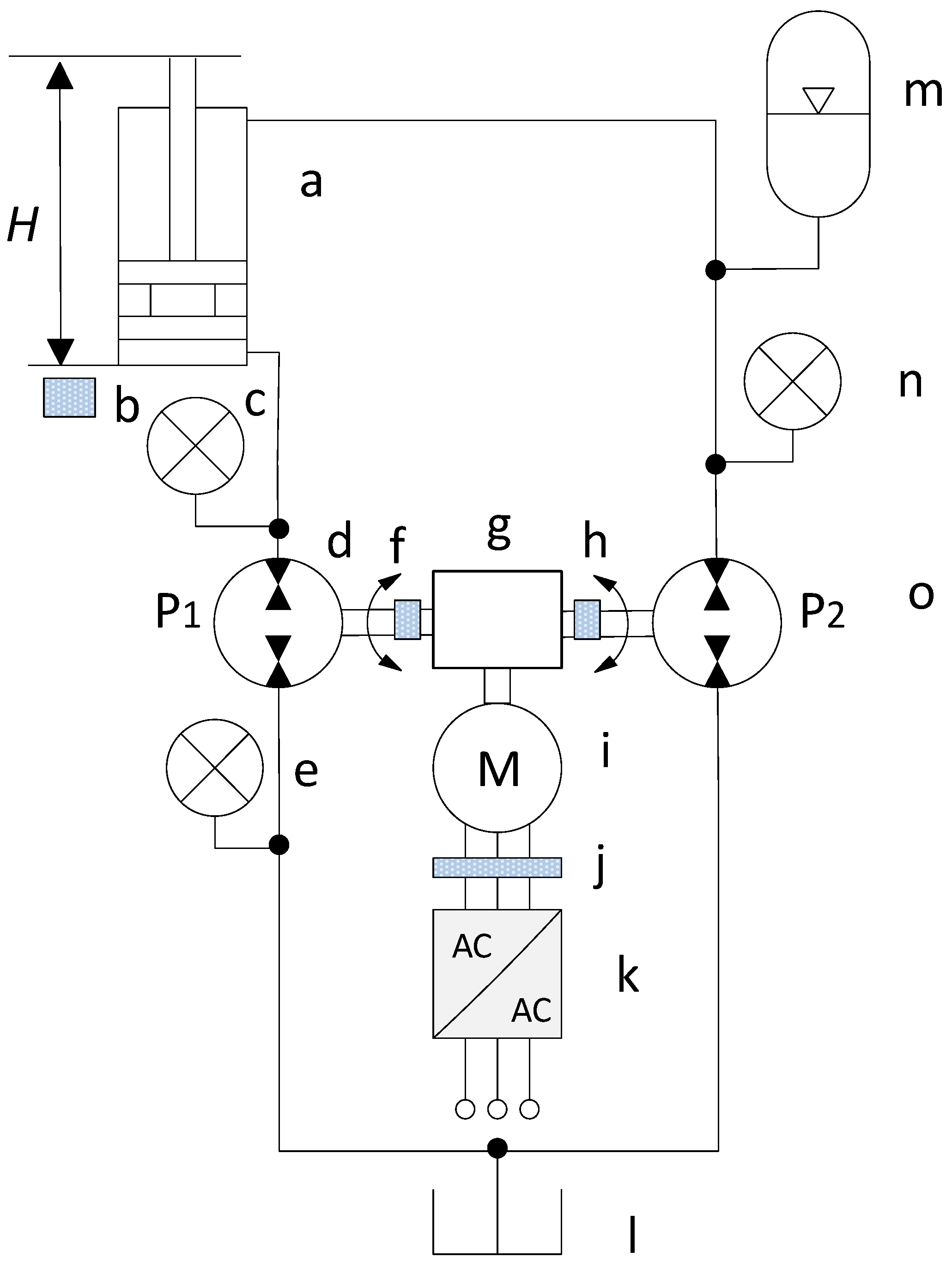
Figure 1 illustrates the simplified experimental test setup of DDH. The setup used a speed-controlled electric servo motor and a frequency converter. The electric motor rotated two hydraulic pump/motors in order to directly control the position of the double-acting cylinder in an open loop control. The lifting–lowering movement cycle, which occurred at different speeds and payloads, was enabled with a program for the electric drive which controlled both the electrical and hydraulic sides of the DDH setup.
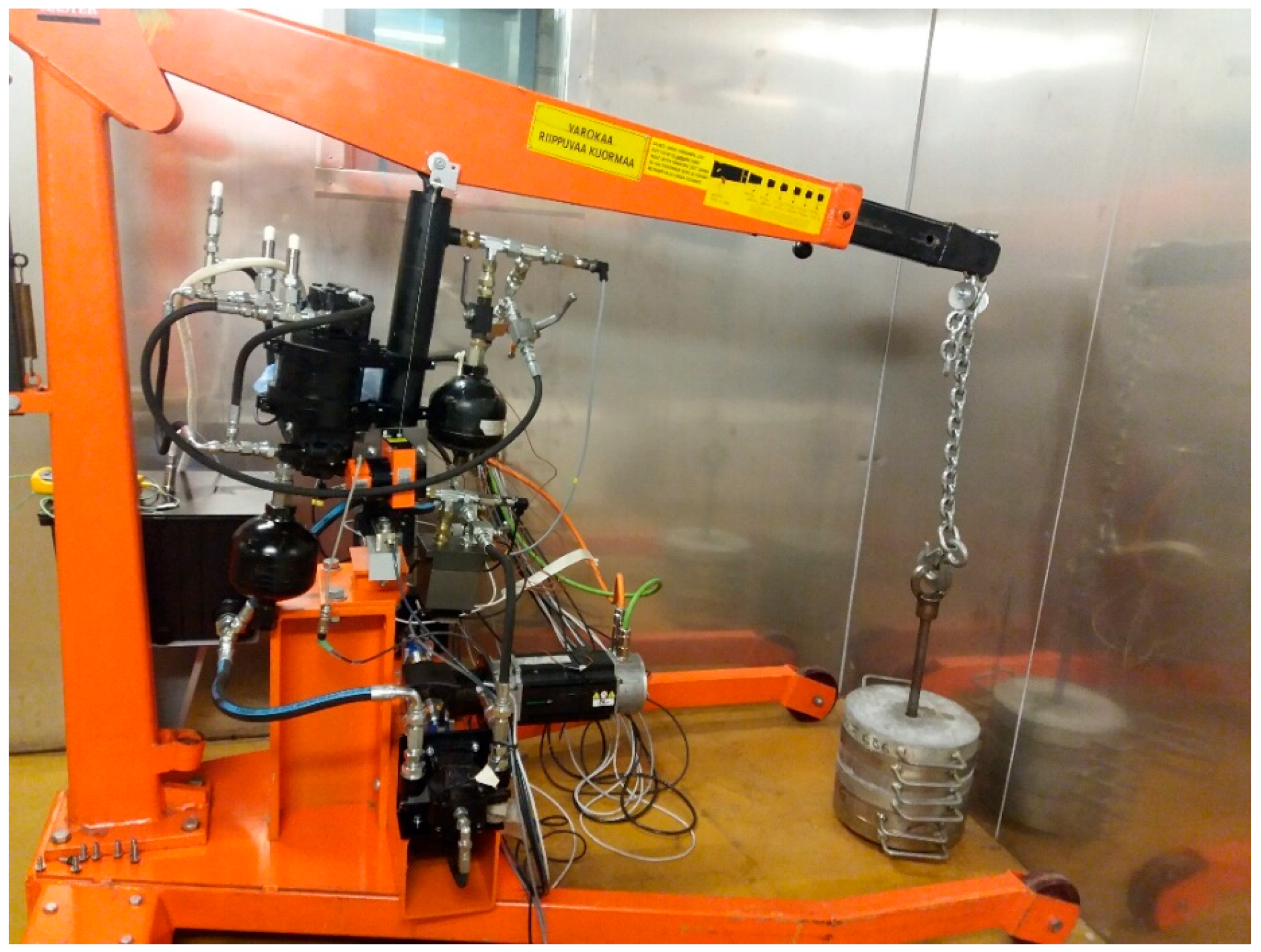
The DDH setup (illustrated in
Figure 1 and
Figure 2) was tested under various conditions in a cold chamber. The cold chamber used for these tests had an adjustable ambient temperature range from −50 °C to +30 °C. The selected ambient temperatures for the experimental investigations were +22 °C, +3 °C, and −10 °C. For each temperature, a set of measurements were performed by varying the payload (0 kg to 120 kg) and motor speed (600 rpm, 800 rpm, 1000 rpm). Thermocouples were used to monitor the initial temperatures on the surfaces and within the test setup at the beginning of each measurement sequence. Each measurement sequence consisted of five actuator lifting–lowering cycles. Each measurement set was only repeated twice due to time constraints related to cold chamber use.
In order to avoid the condensation of moisture in the system, the measurement sets were started at warmer temperatures, progressing to colder temperatures. It took 24 h for the system temperature to equalize from one temperature to the next. System temperatures were allowed to settle for 30 min between measurement sequences. After performing tests with Oil A, the system was returned to room temperature, emptied, cleaned (flushed with fresh oil three times), and refilled with Oil B. The DDH setup was bled, and initial test cycles were performed before starting measurements again to ensure the functionality of the setup after the oil change.
In addition to the temperatures, system oil pressures and flow rates, motor speeds and torques, and cylinder position were all recorded for calculating efficiency values. For efficiency analysis, the rotating speed and torque of the permanent magnet synchronous motor (PMSM) were measured via a frequency converter software.
Figure 1 illustrates the locations of all sensors. Trafag pressure transducers [
28], installed at the pump’s inlet and outlet, were employed to measure the system’s pressures. The actual position of the cylinder’s piston rod was measured by the wire-actuated encoder SIKO SGI (IV58M-0039) [
29], and velocity was calculated later in the control program.
The analysis of efficiency was performed at constant speed areas of upwards motion. At each measurement point, momentary power values were calculated for the system analysis. Power values were used for calculating the efficiency of the system at each measurement point. Due to unpredictable noises in the measurement signals caused by the electric drive, the average values of the calculated efficiencies were used.
The total efficiency of the DDH system was calculated using the equation below, where
ηsystem total is the total system efficiency during the lifting stage of the cycle:
where
PElectric motor is the power input into the system by the electric motor and drive in W, and
PMechanical load is the output power of the system to lift the payload in W. Mechanisms changing geometry during the lifting cycle and its own mass components and inertias were considered in the calculations of the mechanical power output.
The electro-hydraulic efficiency
ηelectro-hydraulic was calculated with the following equation:
where
PHydraulic is the hydraulic power in the system in W.
The hydro-mechanical efficiency
ηhydro-mechanical was calculated with the following equation:
The following section demonstrates the results of the experimental investigation.
3. Results of the Experimental Investigation
Temperature is a determinant parameter in terms of performance, lifespan, and safety. Therefore, the DDH test setup was investigated in a cold chamber with the ambient temperature changing from −10 °C to +22 °C. For this study, two types of oil were utilized: Oil A was a conventional multi-grade hydraulic oil (Super 32), and Oil B was a high-performance oil.
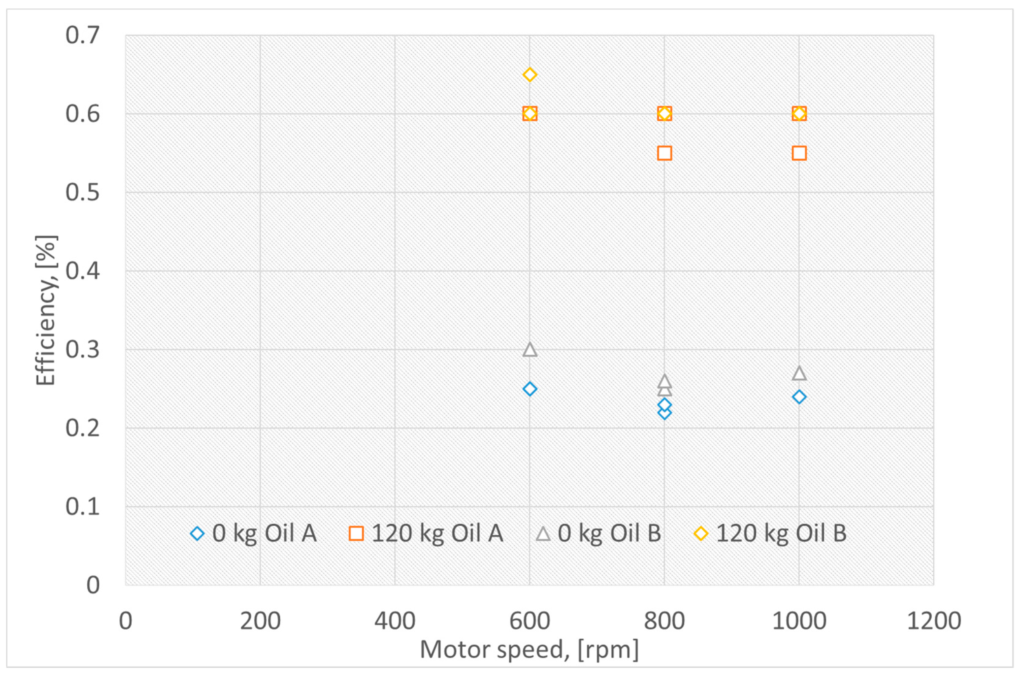
Figure 3 illustrates the effect of temperature on the lifting system total efficiency with oils A and B under various payloads and with an ambient temperature of +22 °C.
Figure 3 shows an improvement of total system efficiency due to Oil B at all motor speeds and loads at the ambient temperature of +22 °C. There was on average a 35%-unit increase in efficiency due to an increase in the payload. With the change of oil under zero payload, there was a 5%-unit increase in efficiency.
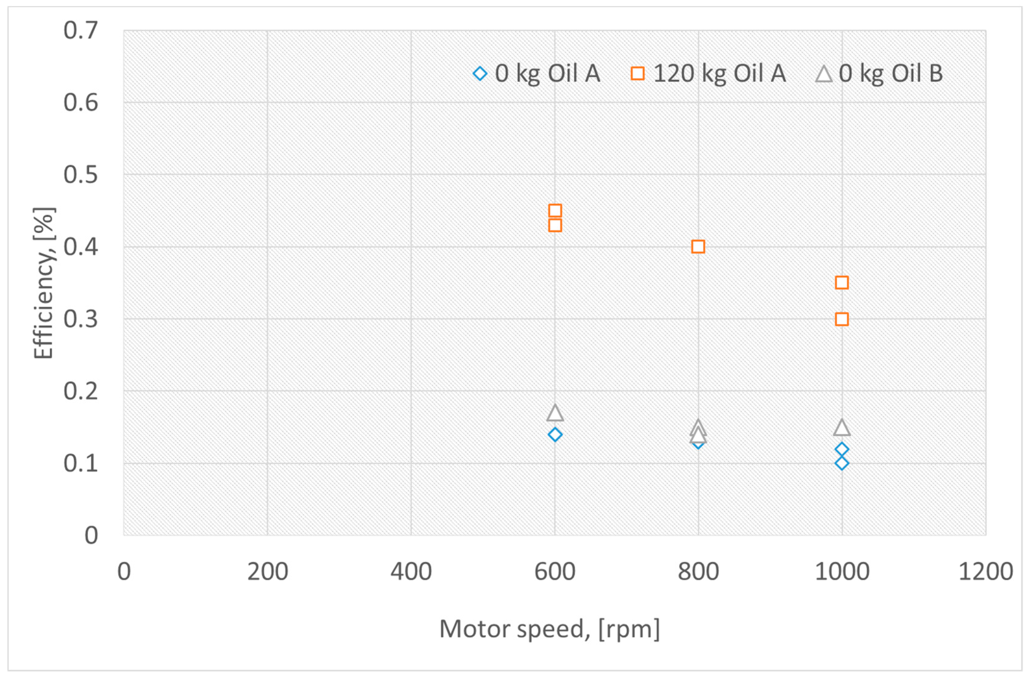
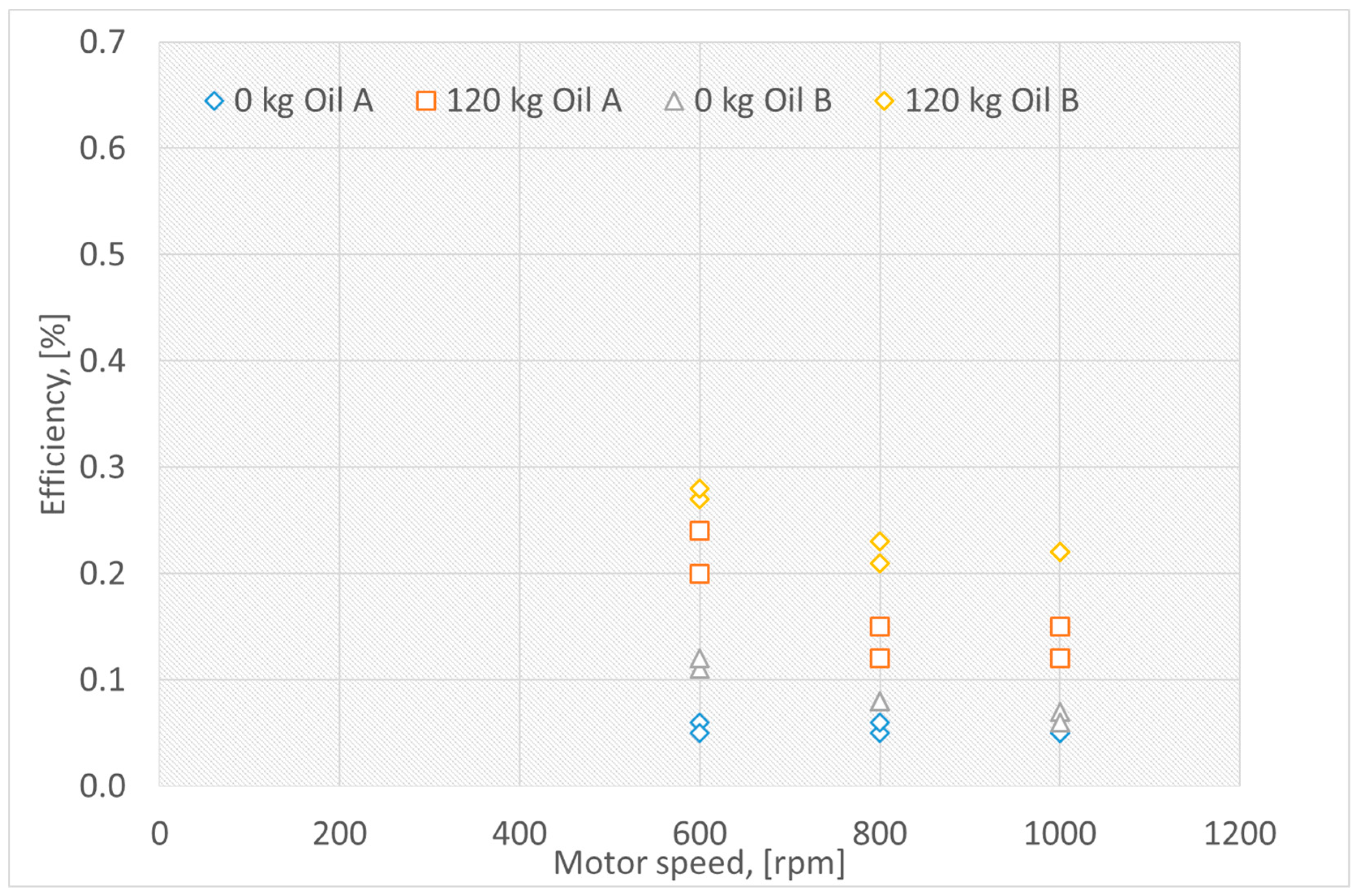
Figure 4 illustrates the effect of temperature on the lifting system total efficiency with oils A and B under various payloads and with an ambient temperature of +3 °C.
In
Figure 4, an increase from 2%-unit to 5%-unit in efficiency with 0 kg of payload can be seen. However, due to technical measurement issues, the new oil measurements for a payload of 120 kg were not available. The difference in efficiencies between zero load and 120 kg load was approximately 29%-unit. The total system efficiency under all payloads and motor speeds dropped with a change from +22 °C to +3 °C in ambient temperature.
Figure 5 illustrates the lifting system total efficiency with oils A and B under various payloads and with an ambient temperature of −10 °C.
In
Figure 5, a significant drop in total system efficiency can be seen compared to temperatures of +22 °C and +3 °C. However, Oil B again resulted in a better system efficiency, with almost a 10%-unit difference compared to the old oil.
Table 1 presents the laboratory test results of the two tested oils before and after the tests. Both oils A and B are hydraulic fluids of viscosity grade ISO VG 32.
Table 1 illustrates that Oil A has a very high viscosity index (VI), which is expected to provide a higher volumetric efficiency. Oil B has a moderate VI and excellent low temperature properties, both of which favor mechanical efficiency.
Figure 6 illustrates an example of the torque curves of two movement cycles of the electric motor of the DDH actuator with both oils at 22 °C and −10 °C and with a payload of 120 kg at 600 rpm. In
Figure 6, the dotted line corresponds to Oil A, and the solid line corresponds to Oil B.
Figure 6 shows that at the same temperature, with Oil B the system used less torque than Oil A. At −10 °C, the system needed a higher torque in order to force the actuator to move downwards. In this case, the electric machine was working in the motoring mode quadrant (negative speed and negative torque). This mode was not required for operation at 22 °C. This applied to both oils.
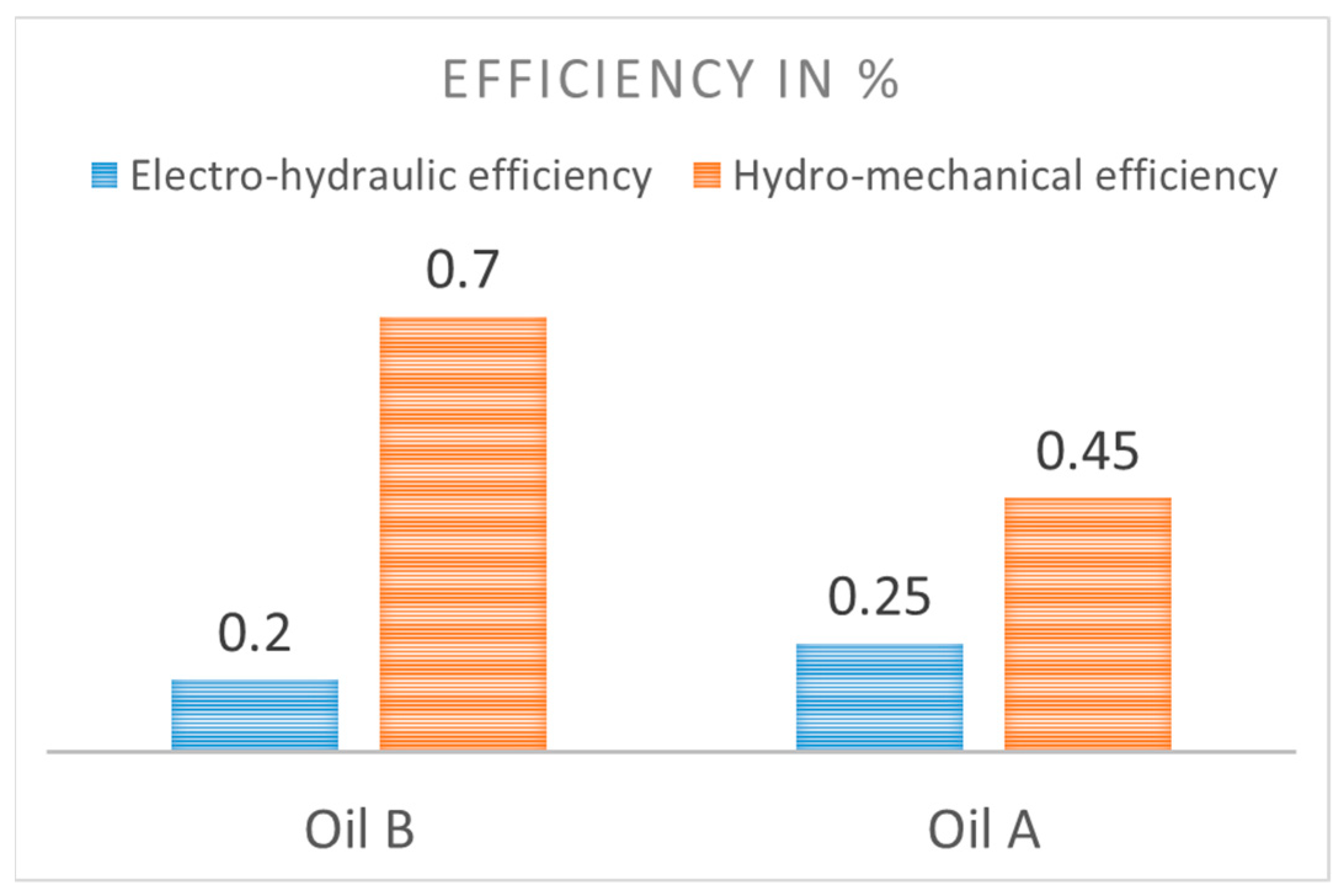
Figure 7 demonstrates the effect of oil on the lifting system efficiency with oils A and B at an ambient temperature of +3 °C. In
Figure 7, electro-hydraulic losses comprise mechanical (shaft, motor, gear) and electric and pump losses. Hydro-mechanical losses in the DDH system were composed of pipe friction losses, elbows and other fittings, entrance and exit losses, losses from changes in pipe size by a reduction in diameter, and cylinder losses. According to
Figure 7, the hydro-mechanical efficiency with Oil B at ambient temperature +3 °C increased compared to values obtained with Oil A, and at the same time there was a minor decrease in electro-hydraulic efficiency.
4. Discussion
The above experiments demonstrated an improvement of the overall system efficiency due to Oil B at all motor speeds and loads and at all tested ambient temperatures. At +22 °C, the change of payload from 0 to 120 kg increased the total system efficiency by an average of 35%-unit. In addition, the difference between oils with 0 kg payload at the same temperature showed a 5%-unit increase in efficiency. At a temperature of +3 °C and 0 kg payload, an increase from 2%-unit to 5%-unit in efficiency was observed. At +3 °C, the increase of efficiencies between 0 and 120 kg payload was approximately 29%-unit. An overall reduction of efficiencies under all combinations of payload and motor speed was observed when lowering the ambient temperature from +22 °C to +3 °C. Also, at an ambient temperature of −10 °C, a significant drop in the overall system efficiency was observed compared to temperatures +22 °C and +3 °C. At −10 °C, despite the overall drop in efficiency, Oil B again gave a better efficiency with nearly a 10%-unit difference when compared to Oil A.
Figure 6 illustrates that the electric motor applied less torque with Oil B than with Oil A at the same temperature. When operating at −10 °C, a motor with a higher torque was needed for both oils to move the actuator downwards due to the lower temperature, and the associated change in oil viscosity appeared to cause more stiffness in the system. It is a known fact that oil viscosity largely depends on the temperature. Cold temperatures are just as dangerous as overheating; extremely cold temperatures affect the lubrication of the system through changes in viscosity. Too high a viscosity in cold temperatures could cause a catastrophic failure of the pump at start-up, while too low a viscosity in high temperatures could accelerate the pump wearing due to compromising the thickness of the protective oil films, causing metal-to-metal contact. The degradation of the oil viscosity is accelerated with temperature variation. In conventional systems, excessive temperatures will oxidize the oil and lead to sludge deposits in the system. As shown in
Figure 7, the hydro-mechanical efficiency with Oil B was better at +3 °C compared to Oil A. However, at the same time, there was a decrease in the electro-hydraulic efficiency.
Serious problems affecting cold weather operations are a direct result of the interaction between cold temperatures and moisture. For instance, running systems in low temperatures will allow condensation to occur in the reservoir, increasing the likelihood of pump cavitation. In addition, the possibility of thermal shocks, which result from a too rapid increase or decrease in temperature, exposes frame components to stress that can lead to damage or permanently reduced service life.
These results are applicable to most non-road mobile machinery for Scandinavian countries, Russia, Canada, and the USA (Alaska). Cold conditions are common in these regions, and considering the expansion of searches for natural resources and the tightening of TIER regulations, this research is becoming increasingly important. These results can help to create future NRMM that are suitable for extreme climate conditions. Furthermore, the investigation of potential aging effects of temperature cycles on selected components and oils with long-term tests and the creation of DDH models in extreme cold conditions are required.
5. Conclusions
Today’s governments of leading countries are applying tighter regulations for the NRMM industry. In response, there is a rising trend to produce more eco-friendly technological solutions. However, in order to meet regulations without significant changes to the NRMMs and without drastically increasing expenses, improving efficiency becomes an important topic to address.
To meet these requirements, this work addresses alternative methods and investigates the effect of hydraulic oil on system efficiency as an affordable solution. A considerable amount of literature on the subject demonstrated that research relating to sub-zero (0 °C) conditions in this area is rather limited. Therefore, to make results more realistic, the utilized temperature test range were set both above and below 0 °C in order to meet the NRMM ambient operating outdoor temperatures, which vary between +50 °C and −40 °C.
In this study, a simplified version of an NRMM—the direct driven hydraulic drive—was utilized.
This research concentrated on analyzing the efficiency of a DDH system in sub-zero environments. In DDH hydraulic systems, the oil flow is controlled directly by the rotational speed of the pump. An experimental investigation proved that the oil properties were important for DDH efficiency, and the efficiency of a DDH system in a cold environment could be significantly improved by switching to high-performance oil (Oil B). Efficiencies were improved by 5%-unit at +22 °C, by 2%-unit to 5%-unit at +3 °C, and by almost 10%-unit at temperatures below zero (−10 °C) by changing from Oil A to Oil B. The results of this study also demonstrated that with the high-performance oil (Oil B), the system used less torque than with the conventional multi-grade oil (Oil A) at the same temperature. However, at sub-zero temperatures (in this case, −10 °C), the system needed higher torque to force the actuator to move downwards in order to follow the requested actuator position. This phenomenon was not observed at 22 °C with either of the oils.
Author Contributions
T.M. performed the experimental investigation, J.H. analyzed the simulation data, and T.S. performed the oil analysis. J.H. and T.M. wrote the paper. M.P. contributed in the discussion of the results.
Funding
The research was enabled by the financial support of Academy of Finland (ArcticWEll project, grant number 289613) and internal funding from the Department of Mechanical Engineering at Aalto University, Finland.
Acknowledgments
This research was enabled by the financial support of the ArcticWEll project (Academy of Finland) and internal funding at the Department of Mechanical Engineering at Aalto University. The fluids were provided by Evonik, a multinational company concentrating on high-growth megatrends, especially health, nutrition, resource efficiency, and globalization.
Conflicts of Interest
The authors declare no conflicts of interest. The founding sponsors had no role in the design of the study; in the collection, analyses, or interpretation of data; in the writing of the manuscript, or in the decision to publish the results.
References
- A Roadmap for Heavy-Duty Engine CO2 Standards within the European Union Framework. September 2017. Available online: https://www.theicct.org/sites/default/files/publications/EU-HDV-CO2-engine-stds_ICCT-Briefing_04092017_vF.pdf (accessed on 4 October 2018).
- DieselNet. United States: Nonroad Diesel Engines, Tier 4 Emission Standards. Available online: https://www.dieselnet.com/standards/us/nonroad.php#tier4 (accessed on 8 March 2018).
- Casoli, P.; Riccò, L.; Campanini, F.; Bedotti, A. Hydraulic Hybrid Excavator—Mathematical Model Validation and Energy Analysis. Energies 2016, 9, 1002. [Google Scholar] [CrossRef]
- Liukkonen, M.; Lajunen, A.; Suomela, J. Comparison of different buffering topologies in FC-hybrid non-road mobile machineries. In Proceedings of the 7th IEEE Vehicle Power and Propulsion Conference, Chicago, IL, USA, 6–9 September 2011. [Google Scholar]
- Lin, T.; Huang, W.; Ren, H.; Fu, S.; Liu, Q. New compound energy regeneration system and control strategy for hybrid hydraulic excavators. Autom. Constr. 2016, 68, 11–20. [Google Scholar] [CrossRef]
- Zimmerman, J.D.; Pelosi, M.; Williamson, C.A.; Ivantysynova, M. Energy consumption of an LS excavator hydraulic system. In Proceedings of the ASME 2007 International Mechanical Engineering Congress and Exposition, Seattle, WA, USA, 11–15 November 2007; pp. 117–126. [Google Scholar]
- Hassi, T.; Korva, A.; Markkula, S.; Partanen, T.; Sourander, T.; Kiviluoma, P.; Korhonen, A.; Kuosmanen, P.; Otto, T. Improving Energy Efficiency of an Electric Mini Excavator. In Proceedings of the International DAAAM Baltic Conference, Industrial Engineering, Tallinn, Estonia, 20–22 April 2016. [Google Scholar]
- JCB’s first ‘electric’ excavator breaks ground. Available online: https://www.agriland.ie/farming-news/jcbs-first-electric-excavator-breaks-ground/ (accessed on 20 March 2018).
- 17VXE Electric Mini Excavator. Available online: http://ihicompactexcavator.com/product/17vxe-electric-mini-excavator/ (accessed on 15 June 2018).
- Sennebogen. Electric Excavator. 2018. Available online: https://www.sennebogen.com/en/products/electric-excavator.html (accessed on 30 June 2018).
- Volvo. Volvo Ce Unveils 100% Electric Compact Excavator Prototype. 2017. Available online: https://www.volvoce.com/global/en/news-and-events/news-and-press-releases/volvo-ce-unveils-100-percent-electric-compact-excavator-prototype/ (accessed on 30 June 2018).
- Edamura, M.; Ishida, S.; Imura, S.; Izumi, S. Adoption of Electrification and Hybrid Drive for More Energy-Efficient Construction Machinery. Hitachi Rev. 2013, 62, 118–122. [Google Scholar]
- Kagoshima, M. The Development of an 8 Tonne Class Hybrid Hydraulic Excavator SK80H. Kobelco Technol. Rev. 2012, 31, 6–11. [Google Scholar]
- Minav, T.; Schimmel, T.; Murashko, K.; Åman, R.; Pyrhönen, J.; Pietola, M. Towards better energy efficiency through systems approach in an industrial forklift. Proc. Inst. Mech. Eng. Part D 2014. [Google Scholar] [CrossRef]
- Minav, T.A.; Schimmel, T.; Pietola, M. Towards Better Energy Regeneration and Efficiency through Hydraulic Fluid Selection in an Electro-Hydraulic Forklift; IFK: Aachen, Germany, 2014. [Google Scholar]
- Minav, T.; Bonato, C.; Sainio, P.; Pietola, M. Direct Driven Hydraulic Drive; IFK: Aachen, Germany, 2014. [Google Scholar]
- Alibert, M.J.; Deneen, D.H.; Herzog, S.N.; Neveu, C.D. Impact of Hydromechanical Losses on Hydraulic Pump Efficiency as a Function of Pressure, Temperature and Fluid Viscometric Properties; STLE Paper; STLE: Park Ridge, IL, USA, 2010. [Google Scholar]
- Soudunsaari, R. Hydrauliöljy ja Hydraulipumppu Arktissa Olosuhteissa; VTT: Espoo, Finland, 1985. [Google Scholar]
- Karlen, H. Hydarulimoottori Arktisissa Oloissa; VTT: Espoo, Finland, 1983. [Google Scholar]
- Välttilä, J. Radial Shaft Seals in Arctic Conditions; SAE Technical Paper 940099; SAE: Warrendale, PA, USA, 1994. [Google Scholar] [CrossRef]
- Mikkonen, S.; Soudunsaari, R. Hydraulikomponenttien O-Rengastiivisteet Arktisissa Olosuhteissa; VTT: Espoo, Finland, 1985; p. 25. [Google Scholar]
- Kauhaniemi, I.; Mikkonen, S. Hydrauliletkut Arktisissa Olosuhteissa; VTT: Espoo, Finland, 1985; p. 27. [Google Scholar]
- Stecki, J.S.; Szewczyk, K.; Lisowski, E. Research on the Behavior of Heavy Mobile Machinery in Simulated Subzero Conditions; SAE Technical Paper; SAE: Warrendale, PA, USA, 1992. [Google Scholar]
- Stecki, J.S.; Szewczyk, K.; Lisowski, E. The Behavior of Hydraulic Systems in Low Operating Temperatures; SAE Technical Paper; SAE: Warrendale, PA, USA, 1992. [Google Scholar]
- Minav, T.A.; Bonato, C.; Sainio, P.; Pietola, M. Efficiency Direct Driven Hydraulic Drive for Non-Road Mobile Working Machines. In Proceedings of the 2014 International Conference on Electrical Machines (ICEM), Berlin, Germany, 2–5 September 2014. [Google Scholar]
- Lodewyks, J.; Zurbrügg, P. Decentralized energy-saving hydraulic concepts for mobile working machines. In Proceedings of the 10th International Fluid Power Conference, Dresden, Germany, 8–10 March 2016. [Google Scholar]
- Weber, J.; Beck, B.; Fischer, E.; Ivantysyn, R.; Kolks, G.; Kunkis, M.; Lohse, H.; Lübbert, J.; Michel, S.; Schneider, M.; et al. Novel System Architectures by Individual Drives. In Proceedings of the 10th International Fluid Power Conference, Dresden, Germany, 8–10 March 2016. [Google Scholar]
- Trafag Sensors Transmitter NAT 8252. Available online: https://www.trafag.com/en/products/product/product/show/8252-nat-industrial-pressure-transmitter/ (accessed on 7 September 2017).
- SIKO SGI (IV58M-0039). Available online: http://www.siko-global.com/en-de (accessed on 12 October 2013).
© 2019 by the authors. Licensee MDPI, Basel, Switzerland. This article is an open access article distributed under the terms and conditions of the Creative Commons Attribution (CC BY) license (http://creativecommons.org/licenses/by/4.0/).


