Grounding System Cost Analysis Using Optimization Algorithms
Abstract
1. Introduction
2. Representation of the Grounding System Material Cost Function to Prevent Electric Shocks
- (1)
- Current that causes a slight tingling sensation when it passes through the fingertips is called a perception current [7]. The minimum current that can be felt is known as the perception current threshold. Note that the threshold is not related to the duration of the current flow. The American National Standards Institute (ANSI) Std. 80 identifies the perception current threshold as 1 mA [3], and the International Electrotechnical Commission (IEC) sets the threshold at 0.5 mA (IEC 479-1) [6].
- (2)
- Current that causes discomfort but does not hinder muscle control is referred to as a let-go current. As the current increases, heat and tingling sensations increase, and when the current reaches a certain level, the muscles contract, causing muscle spasms, and the current-carrying body becomes unable to let go of the contact point. Generally, let-go currents do not cause adverse effects. The let-go current threshold represents the current value that a human body can tolerate without adverse effects. The ANSI Std. 80 sets the let-go current threshold for women and men at 6 and 9 mA, respectively, and the IEC sets the threshold value at 10 mA for both men and women. When the current exceeds this threshold, people may panic and experience unbearable pain. Depending on the duration, currents that exceed the threshold may result in a coma, suffocation, and even death.
- (3)
- The current that causes a rapid disorganized electrical activity in the heart is called a ventricular fibrillation current. The heart functions in humans are controlled by an internal electrical system, and when an external current exceeds the let-go threshold and continues to increase, the heart’s normal electrical signals become disturbed and myocardial vibration is induced (i.e., ventricular fibrillation occurs). If the heart cannot pump blood normally, death can occur within minutes.
3. System Structure
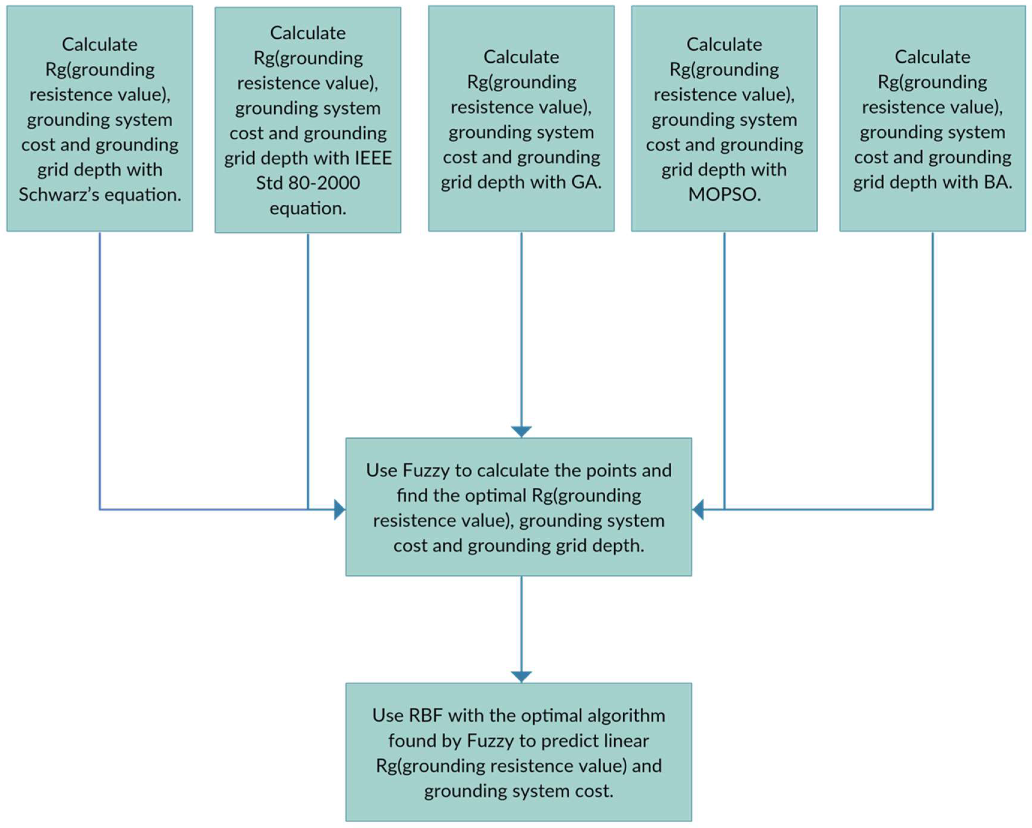
3.1. Grounding Prediction System
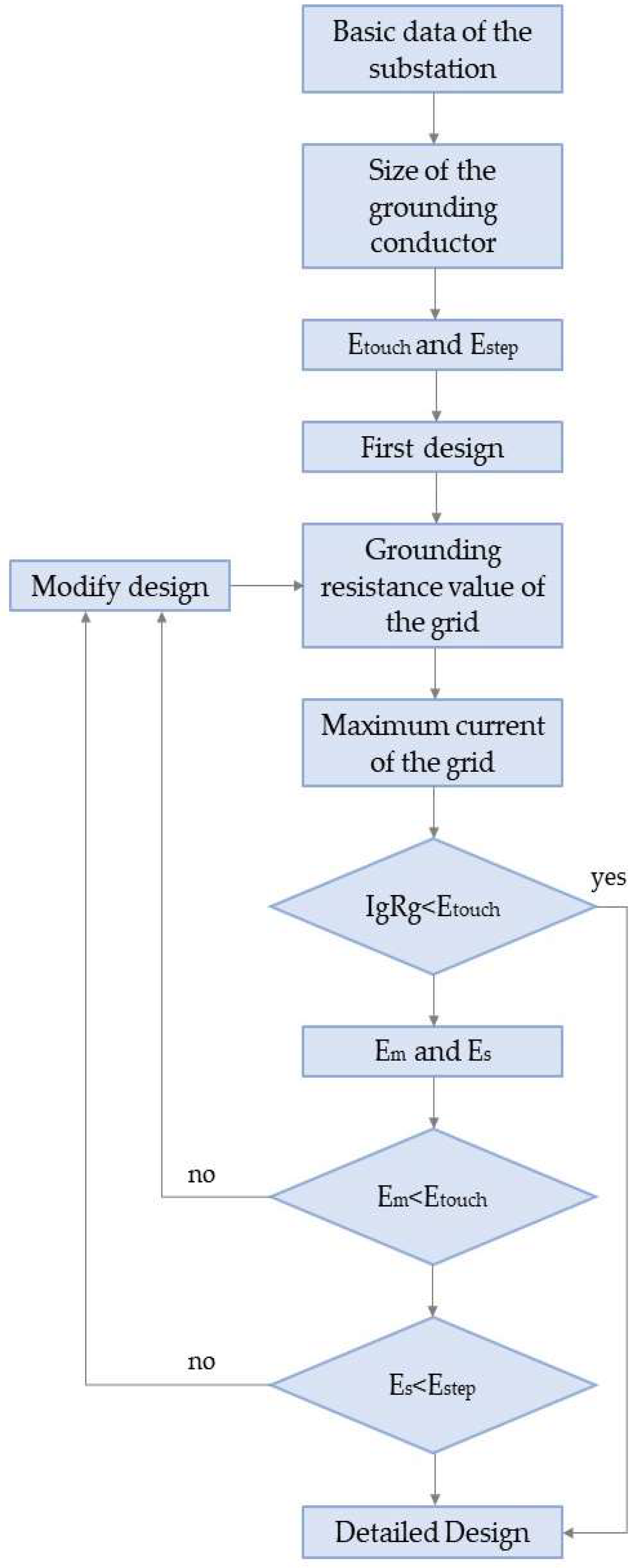
3.2. Grounding Resistance Design
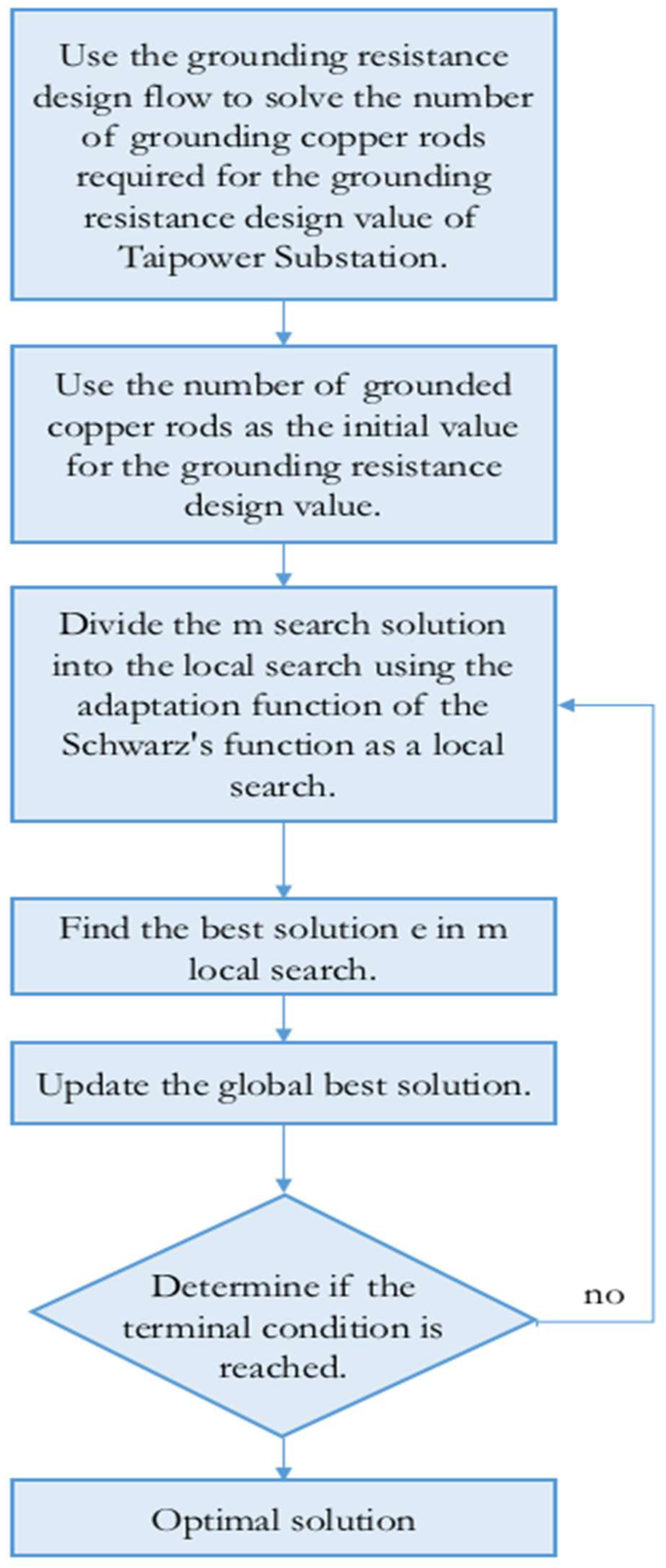
3.3. GA Optimization Flow Chart
3.4. MOPSO Flow Chart
3.5. Artificial Bee Swarm Algorithm Flowchart
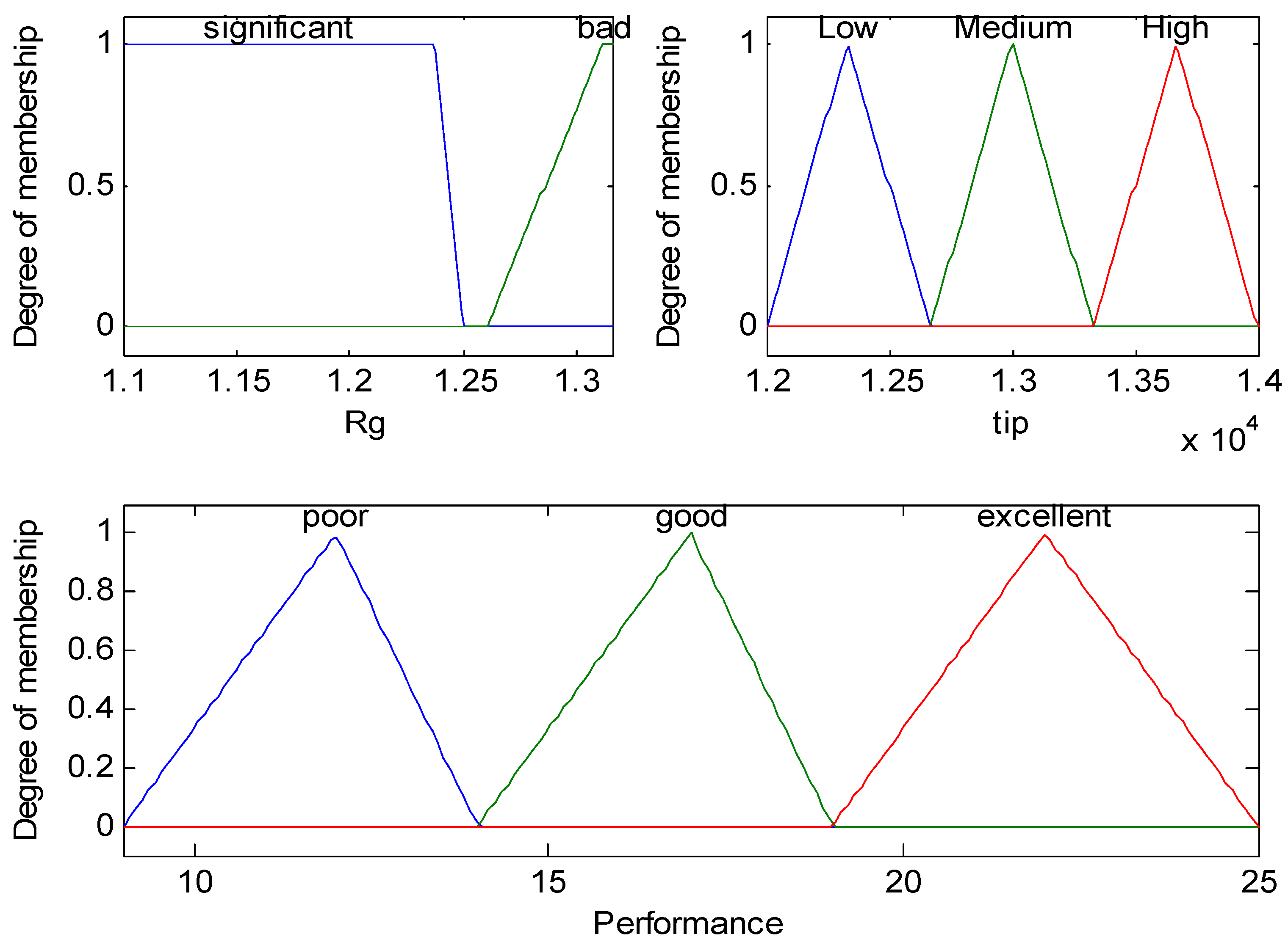
3.6. Fuzzy Integral
3.7. RBF Neural Network
4. System Simulation
5. Conclusions
- (1)
- The grounding system data were optimized with numerous set solutions for GA, MOPSO, and Bees for same grounding target values.
- (2)
- By establishing a fuzzy integral table to count the score of the optimization algorithms, IEEE Std 80-2000, and Schwarz, we identified a suitable algorithm for optimizing the grounding system.
- (3)
- Using the RBF neural network as the prediction line of the grounding system is conducive to different soil layer resistivity in different regions, and it can predict the optimal grounding resistance and grounding system cost.
Author Contributions
Funding
Acknowledgments
Conflicts of Interest
Appendix A
| A. Target Value of Grounding Resistance | ||
| 1. Maximum single-phase grounding malfunction current If | 34.3 kA | |
| 2. Main neutral point shunt In | 0 kA | |
| 3. Grounding current shunt rate at fault K | 0.9 | |
| 4. Maximum allowable touch voltage value (consider surface resistance coefficient = 3000 Ω-m) Et = 902 V | ||
| 5. Safety coefficient (the fence is not connected to the ground network) α = 5 | ||
| 6. Target value of grounding resistance () | ||
| (a) Fault current flowing into the earth through the ground network is Ie = (If − In) × (1 × k) | 3430 A | |
| (b) Ground network allowable maximum voltage rise value V = Et × α, 902 × 5 = 4510 V | ||
| (c) | 1.315 Ω | |
| B. Design Data | ||
| 1. Earth resistance coefficient | 176 Ω-m | |
| 2. Grounding wire of the grid | 80 cm2 | 1650 m |
| 3. Laying area of the grid | 75 × 27 = 5025 m2 | |
| 4. Grounding copper rod (diameter:14mm ∮ length: 2.4 m) | 82 pieces | |
| C. Formulas | ||
| = | ||
| = | ||
| = | ||
| D. Calculation Results | ||
| Laying depth of grids | 0.6 m | |
| R11 | 1.25 Ω | |
| R22 | 1.72 Ω | |
| R12 | 1.17 Ω | |
| Synthetic resistance | 1.238 Ω (design value ≤ target value) | |
References
- IEEE. Std 80TM-2013: Revision of IEEE Std 80-2000, IEEE Guide for Safety in AC Substation Grounding; American National Standards Institute (ANSI): Washington, DC, USA, 2015. [Google Scholar]
- Dalziel, C.F.; Mansfield, T.H. Effect of frequency on perception currents. Trans. Am. Inst. Electr. Eng. 1950, 69, 1161–1168. [Google Scholar] [CrossRef]
- Dalziel, C.F.; Ogden, E.; Abbott, C.E. Effect of frequency on let-go currents. Trans. Am. Inst. Electr. Eng. 1943, 62, 745–750. [Google Scholar] [CrossRef]
- Alik, B.; Teguar, M.; Mekhaldi, A. Optimization of grounding system of 60/30 kV substation of Ain el-Melh using GAO. In Proceedings of the 4th International Conference on Electrical Engineering (ICEE), Boumerdes, Algeria, 13–15 December 2015. [Google Scholar]
- Alik, B.; Teguar, M.; Mekhaldi, A. Minimization of grounding system cost using PSO, GAO, and HPSGAO techniques, IEEE Trans. Power Deliv. 2015, 30, 2561–2569. [Google Scholar] [CrossRef]
- IEC TS 60479-1(1994-09), Effect of Current Passing through Human Body—Part I: General Aspects. Available online: https://webstore.iec.ch/publication/16330 (accessed on 29 September 1994).
- Dalziel, C.F. Dangerous electric currents. Trans. Am. Inst. Electr. Eng. 1946, 65, 579–585. [Google Scholar] [CrossRef]
- Dalziel, C.F.; Massoglia, F.P. Let-go currents and voltages. AIEE Trans. Part II Appl. Ind. 1956, 75, 49–56. [Google Scholar] [CrossRef]
- Dalziel, C.F.; Lagen, J.B.; Thurston, J.L. Electric shock. Trans. Am. Inst. Electr. Eng. 1941, 60, 1073–1079. [Google Scholar] [CrossRef]
- Dalziel, C.F. Electric Shock Hazard. IEEE Spectr. 1972, 9, 41–50. [Google Scholar] [CrossRef]
- Dalziel, C.F.; Lee, W.R. Reevaluation of lethal electric currents. AIEE Trans. Ind. Gen. Appl. 1968, IGA–4, 467–476. [Google Scholar]
- El-Tous, Y.; Alkhawaldeh, S.A. An efficient method for earth resistance reduction using the Dead Sea water. Energy Power Eng. 2014, 6, 47–53. [Google Scholar] [CrossRef]
- Schwarz, S.J. Analytical expressions for the resistance of grounding systems. Trans. Am. Inst. Electr. Eng. Part III Power Appar. Syst. 1954, 73, 1011–1016. [Google Scholar]
- Holland, J. Adaptation in Natural and Artificial System; University of Michigan Press: Ann Arbor, MI, USA, 1975. [Google Scholar]
- Kennedy, J.; Eberhart, R. Particle swarm optimization. In Proceedings of the Fourth IEEE International Conference on Neural Networks, Perth, Australia, 27 November–1 December 1995; pp. 1942–1948. [Google Scholar]
- Shi, Y.; Eberhart, R.C. A modified Particle swarm optimization. In Proceedings of the IEEE International Conference on Evolutionary Computation (ICEC), Anchorage, Alaska, 4–9 May 1998; pp. 69–72. [Google Scholar]
- Hu, X.; Shi, Y.; Eberhart, R.C. Recent advances in particle swarm. In Proceedings of the IEEE Congresson Evolutionary Computation, Portland, OR, USA, 19–23 June 2004; Volume 2, pp. 90–97. [Google Scholar]
- Pham, D.T.; Ghanbarzadeh, A.; Koc, E.; Otri, S.; Rahim, S.; Zaidi, M. “The Bees Algorithm,” Technical Note; Manufacturing Engineering Centre, Cardiff University: Cardiff, UK, 2005. [Google Scholar]
- Zadeh, L.A. Fuzzy sets. Inform. Control 1965, 8, 338–353. [Google Scholar] [CrossRef]
- Chang, Y.W.; Hsieh, C.J.; Chang, K.W.; Ringgaard, M.; Lin, C.J. Training and testing low-degree polynomial data mappings via linear SVM. J. Mach. Learn. Res. 2010, 11, 1471–1490. [Google Scholar]
- Tabatabaei, N.M.; Mortezaeei, S.R. Design of grounding systems in substations by ETAP intelligent software. Int. J. Tech. Phys. Probl. Eng. (IJTPE) 2010, 2, 45–49. [Google Scholar]
- Lee, H.S.; Kim, J.H.; Dawalibi, F.P.; Ma, J. Efficient ground designs in layered soils. IEEE Trans. Power Deliv. 1998, 13, 745–751. [Google Scholar]



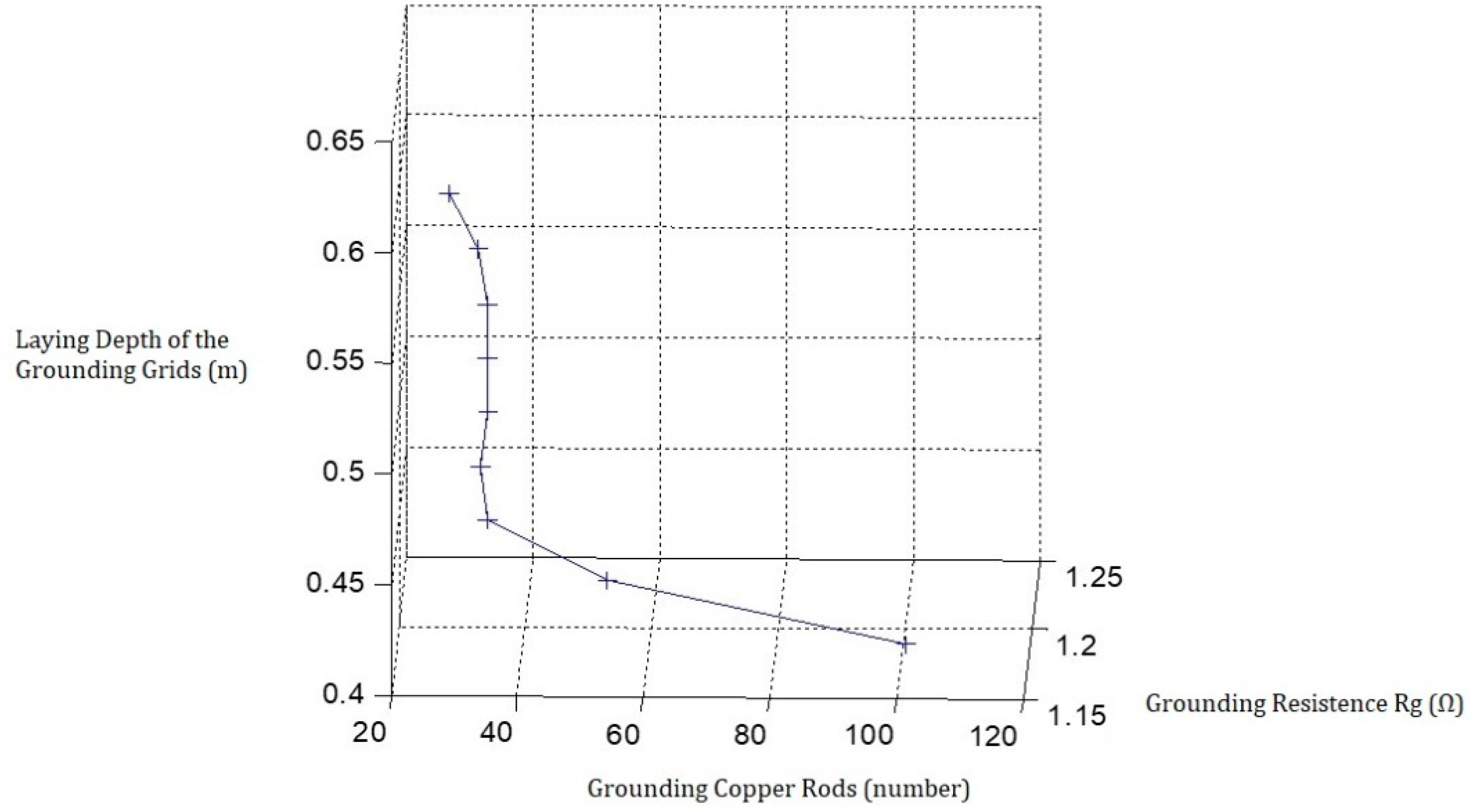
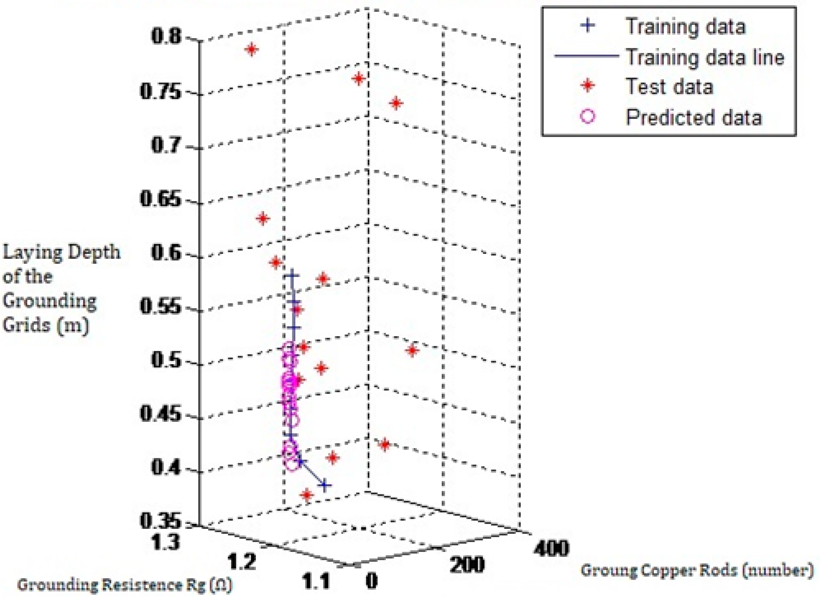
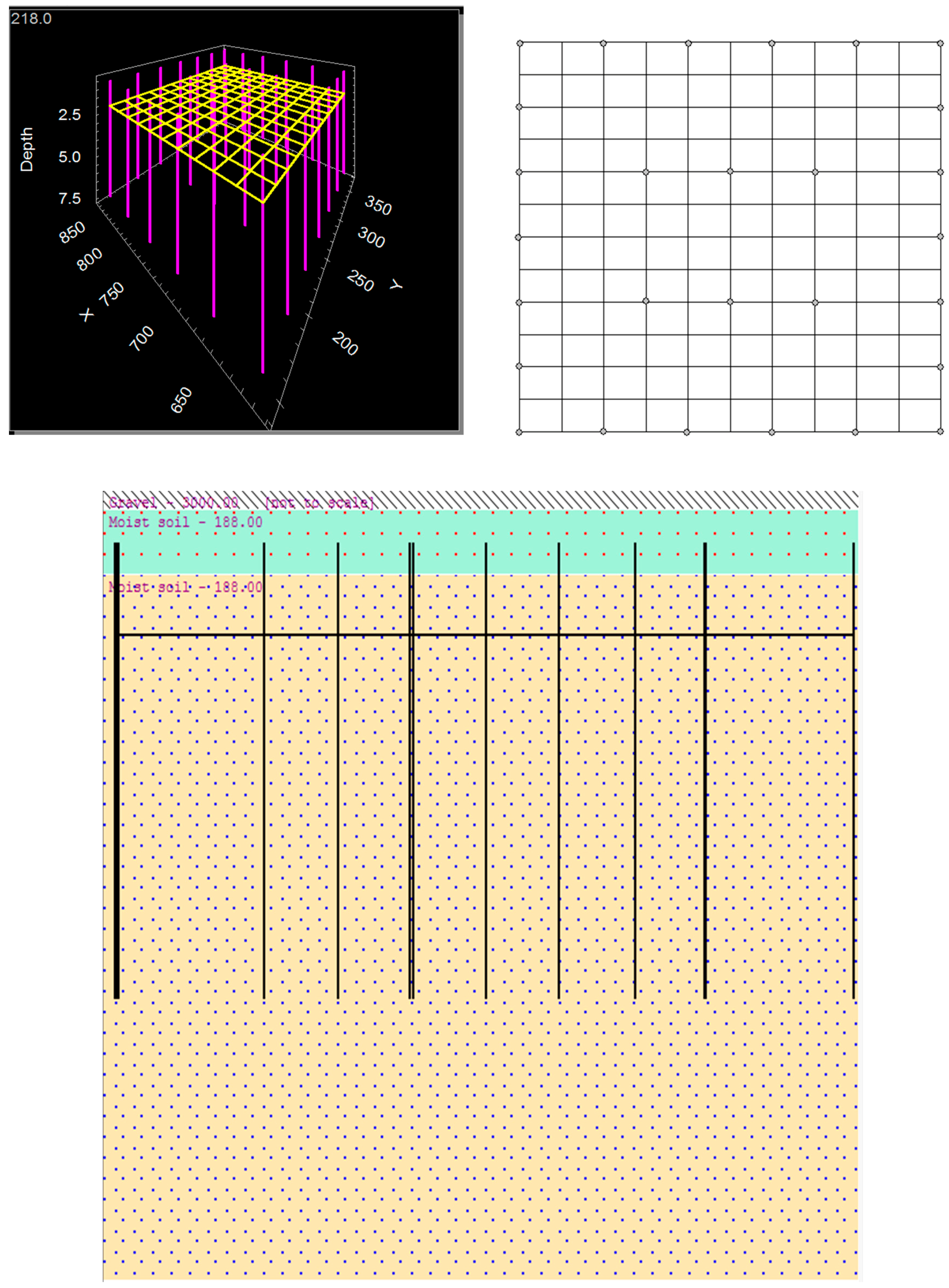


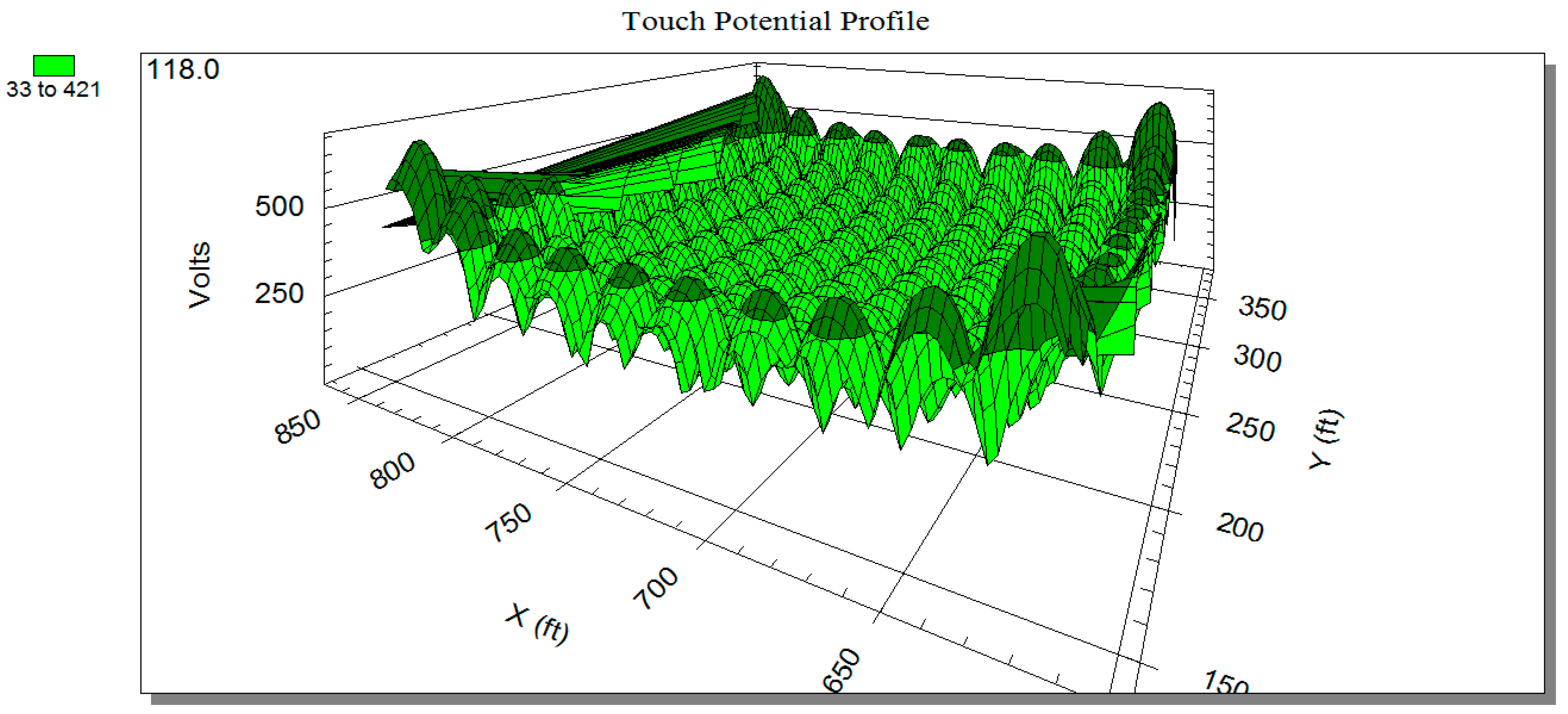
| Parameters of the Grounding-Parameter Algorithm | Grounding Copper Rod (n) | Ground Network Excavation Depth (m) | Grounding Resistance (Ω) | Project Cost | Fuzzy Integral |
|---|---|---|---|---|---|
| Schwarz’s equation | 82 | 0.6 | 1.24 | 13,136.76 USD | 15.0000 |
| IEEE Std. 80-2000 | 82 | 0.6 | 1.19 | 13,136.76 USD | 15.0000 |
| GA | 61 | 0.6 | 1.25 | 12,832.05 USD | 15.0000 |
| MOPSO | 28 | 0.6 | 1.24 | 12,353.22 USD | 19.9989 |
| Bees | 139 | 0.6 | 1.14 | 13,963.83 USD | 13.2965 |
| Laying Depth of Grid (m) | Grounding Copper Rod (n) | Grounding Resistance Rg (Ω) |
|---|---|---|
| h = 0.4 m | 101 | 1.1897 |
| h = 0.425 m | 53 | 1.1949 |
| h = 0.45 m | 34 | 1.1967 |
| h = 0.475 m | 33 | 1.1960 |
| h = 0.5 m | 34 | 1.1950 |
| h = 0.525 m | 34 | 1.1942 |
| h = 0.55 m | 34 | 1.1934 |
| h = 0.575 m | 33 | 1.1927 |
| h = 0.6 m | 28 | 1.1926 |
© 2018 by the authors. Licensee MDPI, Basel, Switzerland. This article is an open access article distributed under the terms and conditions of the Creative Commons Attribution (CC BY) license (http://creativecommons.org/licenses/by/4.0/).
Share and Cite
Perng, J.-W.; Kuo, Y.-C.; Lu, S.-P. Grounding System Cost Analysis Using Optimization Algorithms. Energies 2018, 11, 3484. https://doi.org/10.3390/en11123484
Perng J-W, Kuo Y-C, Lu S-P. Grounding System Cost Analysis Using Optimization Algorithms. Energies. 2018; 11(12):3484. https://doi.org/10.3390/en11123484
Chicago/Turabian StylePerng, Jau-Woei, Yi-Chang Kuo, and Shih-Pin Lu. 2018. "Grounding System Cost Analysis Using Optimization Algorithms" Energies 11, no. 12: 3484. https://doi.org/10.3390/en11123484
APA StylePerng, J.-W., Kuo, Y.-C., & Lu, S.-P. (2018). Grounding System Cost Analysis Using Optimization Algorithms. Energies, 11(12), 3484. https://doi.org/10.3390/en11123484


