Article

Redirection Waveguide having Discrete Translational Symmetry for Photovoltaic Systems with Solar-Cell Units Placed at the Periphery

Research Institute for Electronic Science, Hokkaido University, N20W10 Sapporo, Hokkaido 001-0020, Japan
*
Author to whom correspondence should be addressed.
Energies 2018, 11(12), 3498; https://doi.org/10.3390/en11123498
Submission received: 13 November 2018 / Revised: 8 December 2018 / Accepted: 13 December 2018 / Published: 14 December 2018
(This article belongs to the Section A: Sustainable Energy)

Abstract

:
We have investigated a new type of redirection waveguides for concentration solar-cell systems. The solar cell units are to be placed in the peripheral region of the waveguide. The redirection waveguide converts three-dimensionally propagating (3D) photons into 2D photons that propagate in a planar waveguide which serves as the mainstream of the redirection waveguide. In this new type, the cladding layer on one side of the planar waveguide, not being spatially continuous, tangentially touches the core of the planar waveguide which, having an open geometry, is connected, through tributary waveguides, to the bottom plane where the 3D-photons come in vertically. Based on simulations, we have shown not only that good mainstream-to-mainstream propagation of light-wave can be obtained but also that the light propagation from the tributary waveguides to the mainstream is well done. We also have confirmed that light-waves from the tributary waveguides are well merged with those from the mainstream waveguide at the junction of the cores of the mainstream and the tributary waveguides. Light-waves injected from tributary waveguides propagates well in the core of the mainstream waveguide passing those junctions. The light-wave merging can be fulfilled in the waveguide with the discrete translational symmetry. Photons are shown to be well conveyed in the new waveguide losslessly for a distance of ~1 mm. The redirection waveguide is promising for the concentration photovoltaic systems with solar-cell units placed at its periphery.

1. Introduction

Many types of conventional solar cells studied so far [1,2,3], including tandem solar cells, have difficulty in converting the full spectrum of sunlight into electrical energy. Achieving an ultimate conversion efficiency as high as the thermodynamic limit is one of the major challenges. In an approach to achieve potentially lower cost in solar photovoltaic generation, luminescent solar concentrators were developed [4,5,6], to the edges of which solar cells are attached. Except for a couple of studies [7,8], direction of the photon propagation being orthogonal to its PN junction, the photo-carrier diffusion is parallel to the photon propagation. In those structures, we need a thick layer to fully absorb the solar light, while we need to have a layer thin enough to collect photo-generated electrons and as many holes as possible, because the lifetimes of those carriers are finite. The conventional solar cells are in a state of trade-off in tuning the semiconductor thickness with respect to the photo-absorption and the collection of photocarriers. Thus, we had proposed a new solar-cell called orthogonal photon-photocarrier-propagation solar cell, in which the light propagates in the direction orthogonal to that of the photocarriers no matter what the type is, i.e., either spiral [9,10,11,12] or planar [13,14]. In the solar cell, photons are absorbed in the direction perpendicular to that of the carrier drift/diffusion, and the aforementioned trade-off between the light absorption and the photocarrier collection could be avoided. Exploiting the orthogonality, we can make the semiconductor stripe wide enough to absorb all the photons maintaining the distance between the p- and N-electrodes (i.e., semiconductor thickness) narrow enough to have most of the photocarriers reach the metal electrodes, which is further assured by placing multiple semiconductor stripes with different energy-gaps in such an order that the incoming photons first meet the widest gap semiconductor, then medium-gaps, and the narrowest in the end, as depicted in the bottom of Figure 1. The structure of our new photovoltaic system being shown in Figure 1 has a translational symmetry along the y-direction. The cross-section in xz-plane is depicted in the bottom of Figure 1. The waveguide plane is set so that the sunlight impinges upon the surface perpendicularly at noon of a day. The photons coming to the whole area of the waveguide shown in the top of Figure 1 are eventually led to the edge of the solar cell units placed at the edge of the waveguide. The redirection waveguide converts the three-dimensionally (3D) propagating sunlight into two-dimensional (2D) light-waves, as depicted in the bottom of Figure 1. The redirection waveguide has following two functions: (1) to make the 3D photons coming with various incident angles go vertically to the 2D waveguide plane, and (2) to change the light-wave propagation direction from vertical to lateral in the 2D waveguide. Note that when the first function is fulfilled, we can forget about the Sun’s angle of elevation defined with respect to the xy-plane in analyzing the light-propagation in region ② and thereafter in Figure 1. Our first model system was a diffraction-based redirection waveguide exploiting refractive index modulation which has a symmetric structure and has a fundamental difficulty [14]. Because the diffraction-based structure is symmetric, there are as many left-going photons (LGPs) as right-going photons (RGPs). The fact that LGPs could be regarded as time-reversed RGPs means that any symmetric structure that makes the 3D propagating photons go right in the 2D waveguide also lets the two dimensional LGPs go back into the 3D space, at the same time, due to the spatial symmetry. Thus, for the symmetric redirection waveguide, the 3D to 2D convertibility cannot be high resulting from this fundamental reason. Accordingly, we have proposed asymmetric redirection waveguides, in which the photons propagate, for example, only toward right-hand side in the 2D waveguide, as is the case in Figure 1.

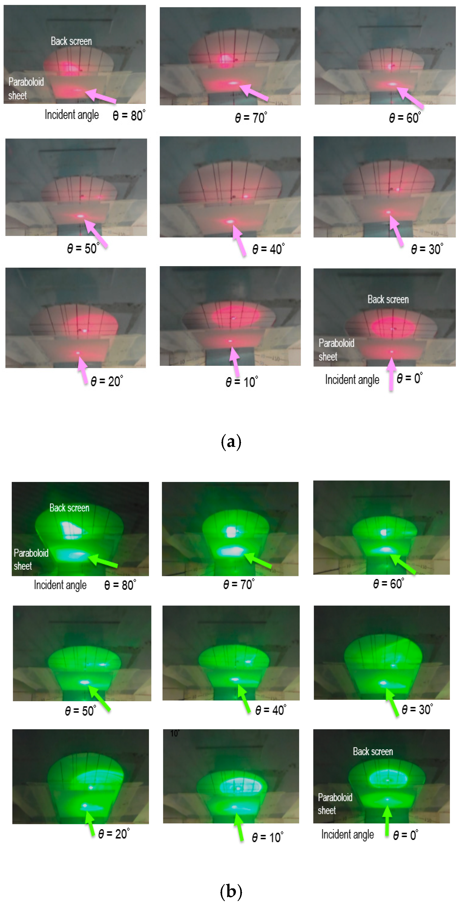
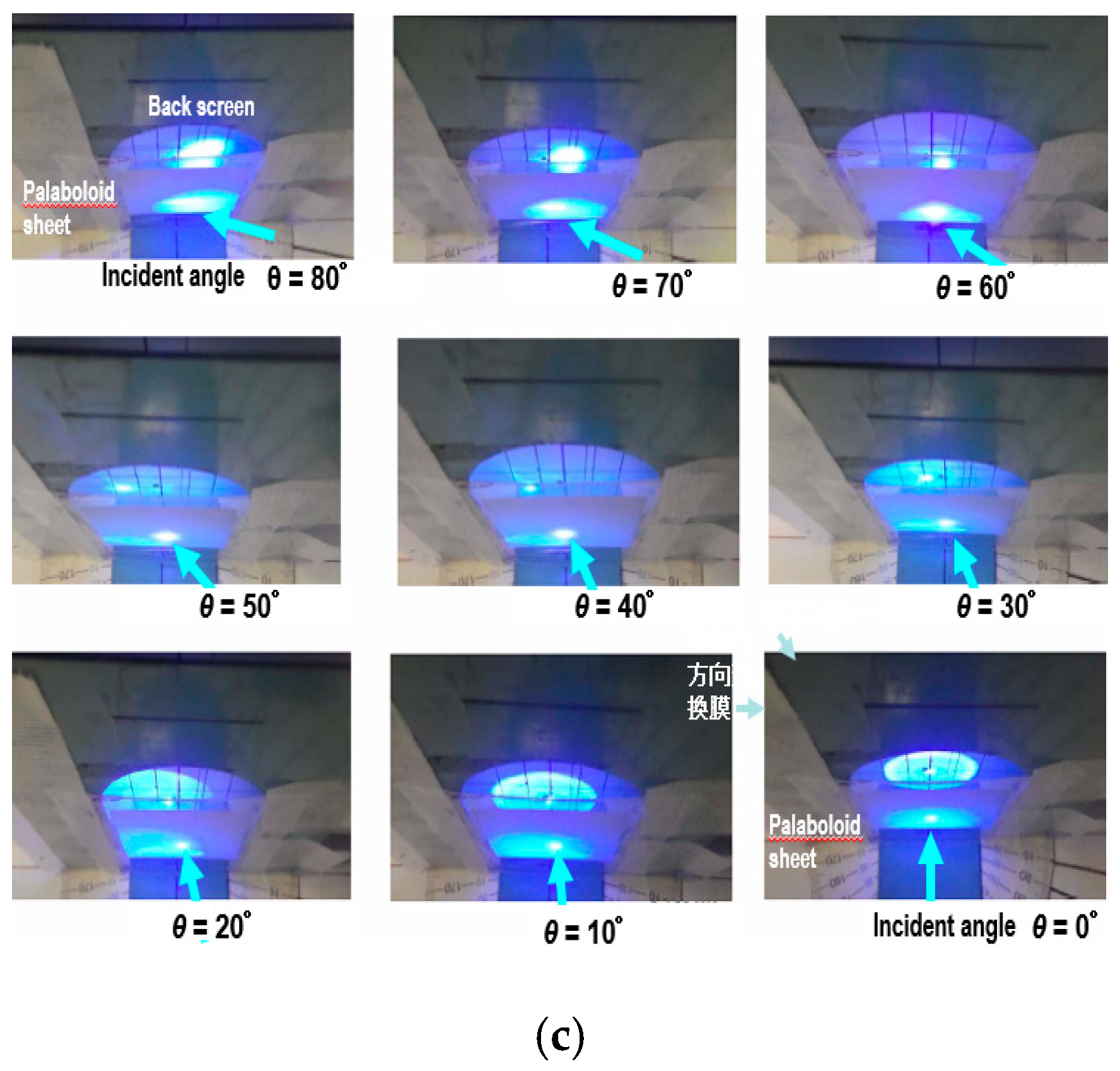
2. Experiments on Photon Propagation-Direction Control with Paraboloid Sheets

Depending on the time in a day, the sunlight comes from the sky above with various incidence angles and the first layer of the redirection waveguide (the region ① shaded with thin vertical lines) in the bottom of Figure 1 is so designed as to make those photons coming with various angles go perpendicularly into the 2D waveguide by, for example, using a thin slab one side of which is covered with densely packed paraboloids (parabola cross-sectioned structures). We have performed simulations for parabola cross-sectioned structures with translational symmetry, i.e., line-and-space structures [15]. One of the advantages of paraboloids over the line-and-space structure having a parabolic cross-section is that as discussed in Section 1, we can forget about the Sun’s angle of elevation defined with respect to the xy-plane because of the circular symmetry of the paraboloid around the z-axis. One of those paraboloid sheets was fabricated using imprinting. Both the height and bottom width of the paraboloid are ~100 μm in the sheet used in the experiment. In Figure 2a,c, we show the results of experiments in which laser beams with different wavelengths coming from beneath impinge on the slab with the aforementioned parabola structure, behind which we put a screen and we can measure how the direction of the laser beam is changed. As shown in Figure 2a–c, for almost all incidence angles of the red laser beam, a strong optical spot is observed on the screen right behind the spot of the impingement of the laser beam on the slab with parabola structures. Although the beam is a little bit weak in intensity and its orthogonality to the screen is not perfect for incidence angles around 40 degrees, the slab structure used as the first layer of the redirection waveguide is now shown experimentally to have the function, in a qualitative agreement with the simulation [15], to make three-dimensionally (3D) photons coming with various angles go almost perpendicularly into the 2D waveguide.

3. Simulations and Discussions.

The second layer of the redirection waveguide (the region ② shaded with thin oblique lines in the bottom of Figure 1) converts the 3D-propagating sunlight into wave-guided 2D-photons that eventually go into the stripe from the edge along the PN junction. For this we propose the structure shown in Figure 3. Thanks to the translational symmetry along the y-direction in Figure 1 and the aforementioned first function of the redirection waveguide of our new photovoltaic system, we can solve the light-propagation by considering only the electromagnetic field in xz-plane, shown in Figure 1 or Figure 3, without losing generality. Simulation of light propagation in the new waveguide for MOP3SC is performed with the Finite-Difference Time-Domain (FDTD) method [16]. In general, in a waveguide [17], photons can propagate in the waveguide with virtually zero-loss to reach out to the other end of the waveguide thanks to the cladding layer that, surrounding/sandwiching the core, has continuous translational symmetry, which, on one hand, ensures the aforementioned characteristics that the light that propagates long distance in the core with extremely low optical losses. On the other hand, however, the conventional structure has a drawback that it is very difficult for external photons to join the core at any intermediate regions between the two ends of the waveguide. Using the structure shown in Figure 3, we face the challenge of realizing a new waveguide structure in which photons can go into the waveguide from the intermediate regions of the 2D waveguide as depicted in the bottom of Figure 1. Note that in this new structure, the bottom cladding layer for the mainstream waveguide being not spatially continuous (see the bottom figure of Figure 3), the mainstream’s core has an open geometry and is connected, through the tributary-waveguide’s cores, to the bottom plane where photons come in vertically thanks to the first layer of the redirection waveguide described in Section 2. The whole waveguide structure has a discrete translational symmetry in marked contrast to the conventional waveguides that has continuous translational symmetry. Due to the discrete cladding structure, the structure can receive the photons coming vertically from beneath along z-axis as depicted in the top of Figure 3.

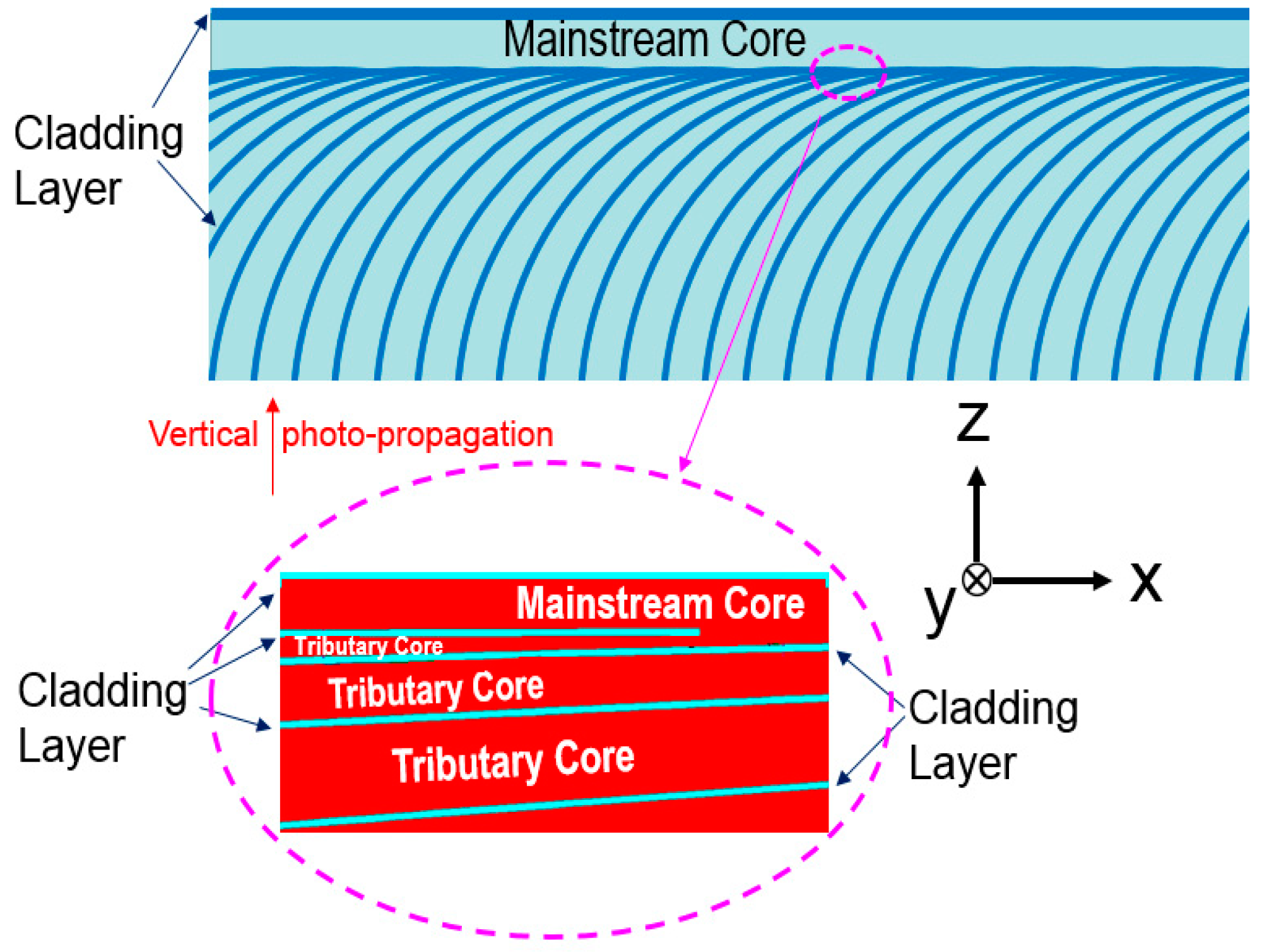
3.1. Light Propagation from the Core to Core of the Mainstream Waveguide

Concerning the new waveguide with the discrete translational symmetry, we have calculated the light propagation based on the aforementioned FDTD. We have cross-checked the simulation result with ‘eigenmode’—expansion propagation tool [18], and confirmed that a fairly good agreement is obtained in calculating the light propagation in the redirection waveguide. Shown in Figure 4 are the structure (top), the optical-field calculated (middle), and the optical field intensity (bottom). The horizontal axis of the bottom figure, being in proportion to the time after the light-wave is emitted from the light source, is roughly equal to the distance the light-wave has traveled when divided by the refractive index n ≈ 2.0. In the calculation, the refractive index of the core of the mainstream and/or tributary curved waveguides is set to be 2.0 and that of the cladding layers 1.35. In this simulation, as shown in the top of Figure 4, the light source is set adjacent to the monitor A, and we placed two monitors A and B to calculate the optical field intensity. We have set the discrete bottom cladding layers to touch the horizontal core tangentially, and as a result the light propagation is not affected much by the openness (discreteness) of the core (the cladding layer) as shown in the middle of Figure 4. As can be seen in the bottom of Figure 4, the intensities evaluated by monitors A and B are identical, showing that photons are not lost even after passing through the open region, located at X ≈ 300 μm, in the mainstream core of this structure.

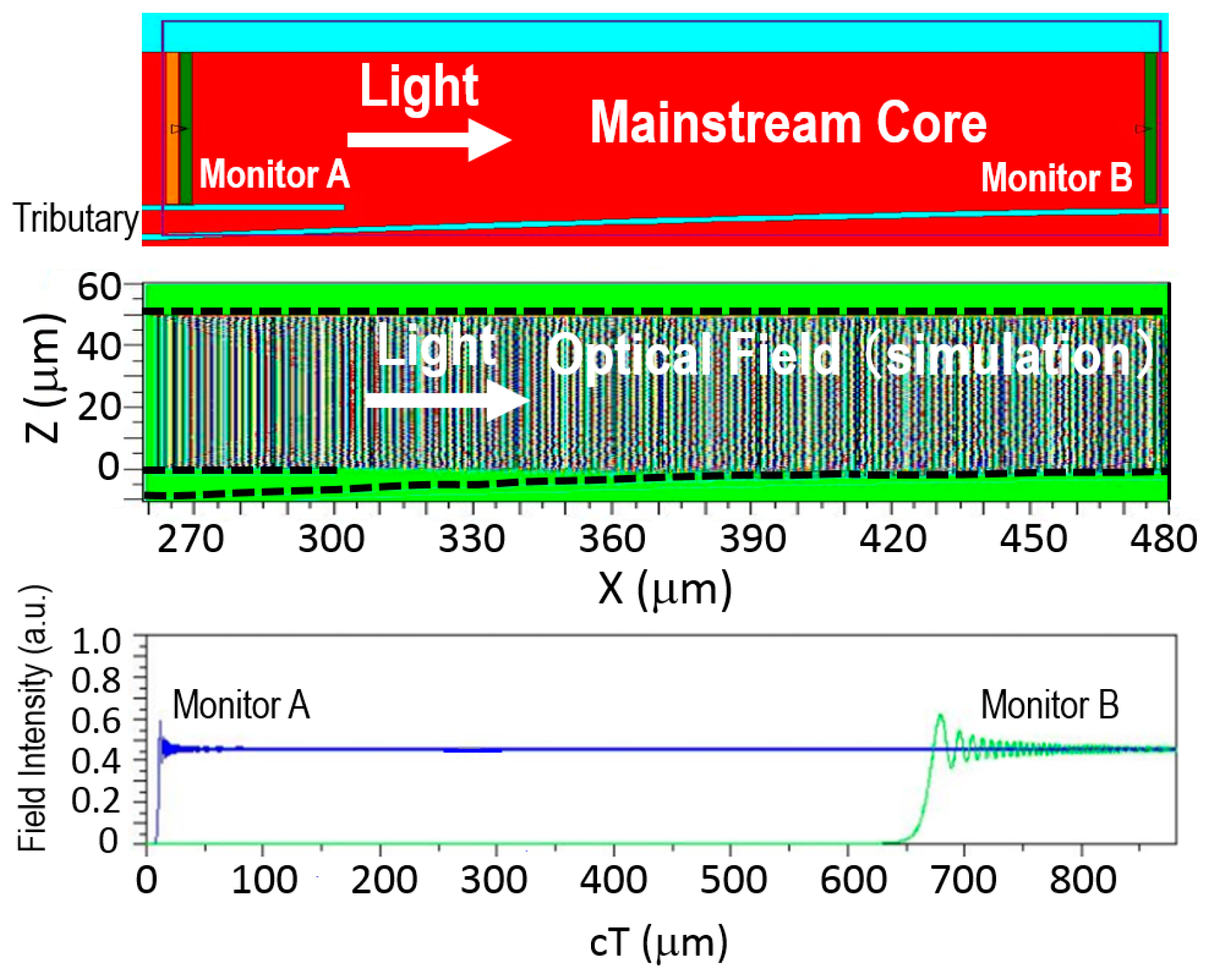
3.2. Light Propagation from Tributary to Mainstream

Next, as shown in Figure 5, we have calculated the light propagation from one of tributary waveguides to the mainstream 2D-waveguide. The structure, including the monitoring positions (top), the optical-field calculated (middle), and the optical field intensity (bottom) is shown in Figure 5. To investigate the light propagation from the tributary waveguide to the mainstream, we set the light source in the tributary. Monitors A, B and C are placed next to the light source, at the merging zone (junction) of the two cores, and at the right end of the structure, respectively, in this calculation. As shown in the middle of Figure 5, indeed diffraction takes place due to the openness at the region where the tributary waveguide merges into the mainstream’s core but by carefully designing the structure so that the incident angle, to the upper cladding layer, of the most diffracted photon is still less than the critical angle, we can make the merge-loss minimum as seen in the bottom of Figure 5, where the intensities evaluated by monitors A, B and C are almost identical. The intensity at Monitor B seems somewhat less than that at Monitor A suggesting there is some loss at the junction around X ≈ 0, but it turns out that it is not the case, as we discuss later in Figure 7 in larger scale. In the bottom of Figure 5, again, cT of the horizontal axis is roughly equal to the distance the light-wave has traveled after the light-wave is emitted from the light source when divided by the refractive index n ≈ 2.0.

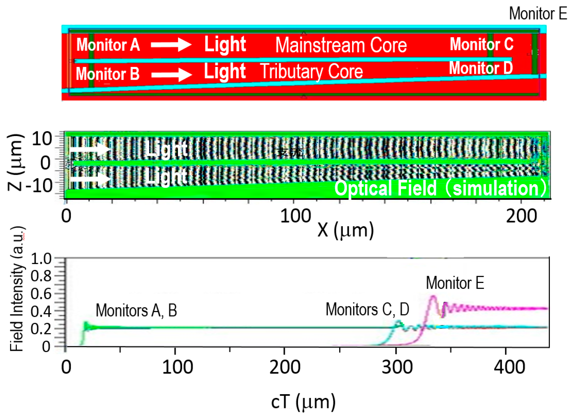
3.3. Merging of Light-Wave from the Mainstream and that from the Tributary

We then have calculated the merging of the light-wave from the mainstream and that from a tributary waveguide. The structure including monitoring positions (top), the optical-field calculated (middle), and the optical-filed intensity (bottom) are shown in Figure 6. To investigate the light propagation in this configuration, we set the light sources both in the mainstream 2D-waveguide and also in the tributary waveguide. Monitors A, and B are placed next to the light source. Monitors C and D are located just before merging at the junction, and monitor E right after the merging of the two cores of the mainstream and tributary. It is natural that the field intensity is the same for monitors A and C, since they are placed at the mainstream whose core is just a simple slab. We note that the intensity at monitor D is same as that at monitor B even if the width of the tributary core is narrowed before the junction around X ≈ 190 μm. The intensity at monitor E at X ≈ 210 μm is doubled when compared to those at Monitors A and B (or at Monitors C and D), which manifests that the light-wave merging can be fulfilled losslessly in the waveguide with the discrete translational symmetry, as intended.

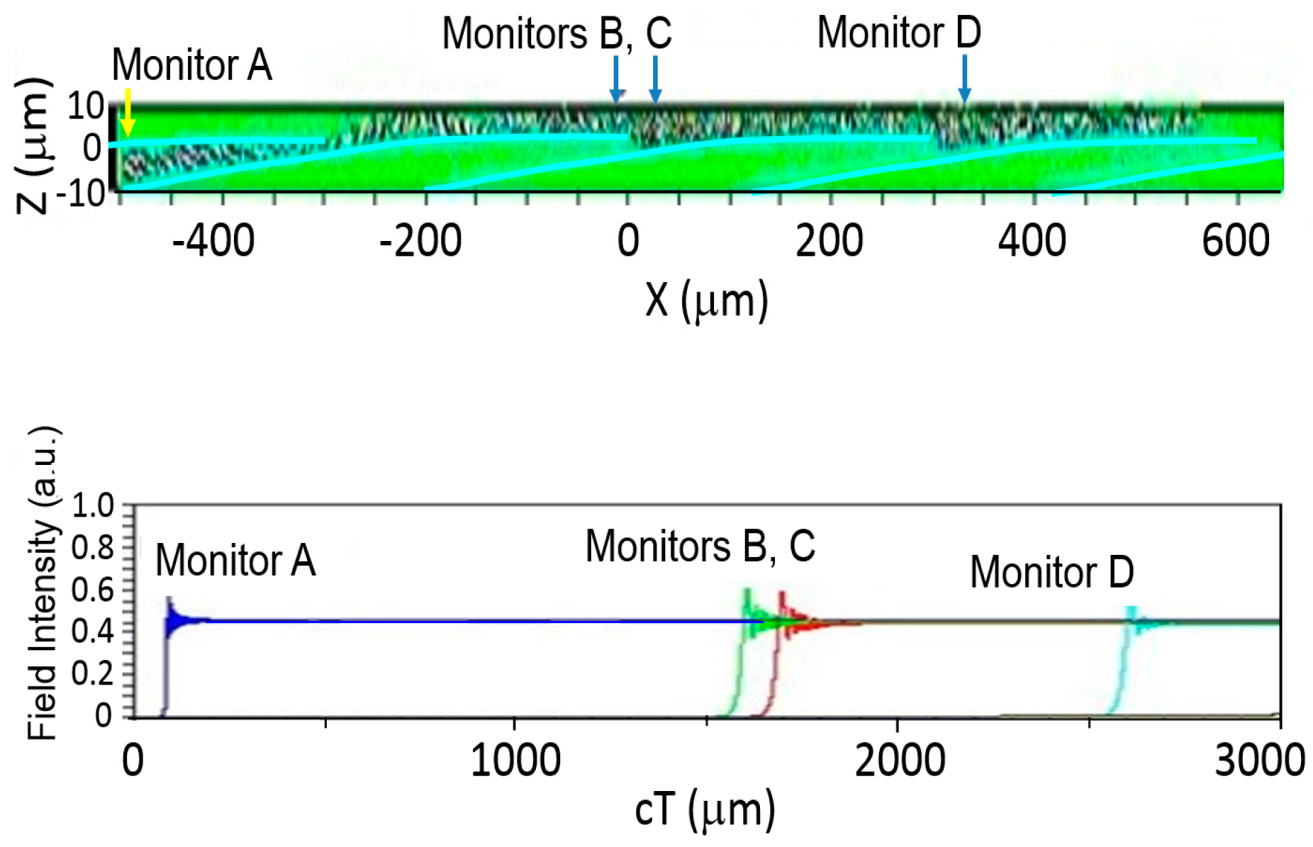
3.4. Light Propagation from Tributary to Mainstream in a Long Distance

Finally, we simulate how light-wave propagate after being introduced from one of the tributary waveguides and going into the mainstream 2D-wavegide. Figure 7 shows the results of the simulation of letting light-waves be introduced from one tributary, propagate in the main planar waveguide for a distance of ~1 mm after passing three junctions of the mainstream and the tributaries. The top figure is the calculated optical field, and the bottom figure shows the optical filed intensities at four monitoring locations A, B, C and D. Monitor A is neighboring to the light source, and monitors B and C are, respectively, right before and after the second junction. Monitor D is placed about 50 microns downstream from the third junction. As shown in the bottom of Figure 7, the optical intensity at monitor D is the same as those at monitors C, B and A, which demonstrates the photons are well conveyed in the new waveguide losslessly for a distance of ~1 mm. By further improving the new waveguide structure that has discrete translational symmetry due to the cladding layer being discontinued periodically, we would be able to make photons coming from the bottom of the structure shown in the top of Figure 3 reach out the right end of the structure where solar-cell units including MOP3SC or other conventional tandem cells are to be placed.

4. Conclusions

For orthogonal photon-photocarrier propagation solar cell (MOP3SC) in which light propagates in the direction orthogonal to that of the photo carriers, we have investigated an asymmetric redirection waveguide that performs 3D to 2D photon-conversion by (1) making the photons coming from various directions go vertically into the 2D waveguide, and (2) by changing the vertically going photons into those that are laterally propagating in the 2D waveguide. Experimentally we have shown that the first layer of the redirection waveguide, i.e., a thin slab with densely packed paraboloids can make those photons that come with various angles go, to a good approximation, perpendicularly to the 2D waveguide that is to convey the light to the solar cell units located at the periphery of the redirection waveguide. As for the second function of the redirection waveguide, we have proposed a new asymmetric waveguide with discrete translational symmetry. The cladding layer on one side of the mainstream core of the asymmetric waveguide is not spatially continuous and tangentially touching the asymmetric waveguide’s 2D core which, then, has an open geometry and is connected, through the tributary waveguides, to the bottom plane where photons come in vertically thanks to the first function of the redirection waveguide. Based on simulations, we have shown that good mainstream-to-mainstream and tributary-to-mainstream propagation of photons would be obtained in the redirection waveguide. Also, the light-wave merging can be fulfilled in the waveguide with the discrete translational symmetry. The photons are well conveyed in the new waveguide losslessly for a distance of ~1 mm. The new waveguide with the discrete translational symmetry would serve, in near future, as a key component for excellent concentration photovoltaic systems with high conversion efficiencies.

5. Patents

PCT/JP2018/035015 “Optical waveguide, photovoltaic device, mobile electronic device, and waveguide for electromagnetic waves” (filed on 21 September 2018) has resulted from the work reported in this paper.

Author Contributions

Conceptualization is done by A.I.; experiments by T.K., calculations by N.S. and A.I. methodology, and writing-review and editing by A.I.

Funding

This research was funded by 2010–2012 Grant-in-Aid for Scientific Research (B) [22350077], 2013–2015 Grant-in-Aid for Scientific Research (B) [25288112], and 2016–2018 Grant-in-Aid for Scientific Research (B) [16H04221] from the Japan Society for the Promotion of Science (JSPS).

Acknowledgments

The authors are thankful to H. Yamagata, Impritecs Corp. for materials for photon-propagation direction-modulation. This work is supported, in part, by Special Education & Research Expenses from Post-Silicon Materials and Devices Research Alliance; JST Seeds Innovation Program; Post-Silicon Materials and Devices Research Alliance; Nano-Macro Materials, Devices and System Research Alliance; Dynamic Alliance for Open Innovation Bridging Human, Environment and Materials; Network Joint Research Center for Materials and Devices; 2010-2012 Grant-in-Aid for Scientific Research (B) [22350077], 2013-2015 Grant-in-Aid for Scientific Research (B) [25288112], and 2016-2018 Grant-in-Aid for Scientific Research (B) [16H04221] from the Japan Society for the Promotion of Science (JSPS).

Conflicts of Interest

The authors declare no conflict of interest.

References

  1. Sze, S.M. Solar cells, In Physics of Semiconductor Devices, 2nd ed.; John Wiley & Sons: New York, NY, USA, 1981; pp. 790–838. [Google Scholar]
  2. Green, M.A.; Hishikawa, Y.; Dunlop, E.D.; Levi, D.H.; Ebinger, J.H.; Ho-Baillie, A.W. Solar cell efficiency tables (version 51). Prog. Photovolt. Res. Appl. 2018, 26, 3–12. [Google Scholar] [CrossRef]
  3. Liu, M.; Jonson, M.B.; Snaith, H.J. Efficient planar heterojunction perovskite solar cells by vapour deposition. Nature 2013, 501, 395–398. [Google Scholar] [CrossRef] [PubMed]
  4. van Sark, W.G.J.H.M.; Barnham, K.W.J.; Slooff, L.H.; Chatten, A.J.; Büchtemann, A.; Meyer, A.; McCormack, S.J.; Koole, R.; Farrell, D.J.; Bose, R.; et al. Luminescent solar concentrators—A review of recent results. Optics Express 2013, 16, 21773–21792. [Google Scholar] [CrossRef]
  5. Li, C.; Chen, W.; Wu, D.; Quan, D.; Zhou, Z.; Hao, J.; Qin, J.; Li, Y.; He, Z.; Wang, K. Large stokes shift and high efficiency luminescent solar concentrator incorporated with CuInS2/ZnS quantum dots. Sci. Rep. 2015, 5, 1–9. [Google Scholar] [CrossRef] [PubMed]
  6. Luminescent Solar Concentrators. Available online: http://uml.chemistry.unimelb.edu.au/research-2/luminescent-solar-concentrators/ (accessed on 7 December 2018).
  7. Suemori, K.; Miyata, T.; Hiramoto, M.; Yokoyama, M. Vertical junction type organic photovoltaic cells. Jpn. J. Appl. Phys. 2004, 43, 1094–1096. [Google Scholar] [CrossRef]
  8. Parrott, J.E. The limiting efficiency of an edge-illuminated multigap solar cell. J. Phys. D: Appl. Phys. 2001, 12, 441. [Google Scholar] [CrossRef]
  9. Ishibashi, A. Solar Cells and Photovoltaic Devices. Jpn. Pat. 4022631, 2007. [Google Scholar]
  10. Ishibashi, A.; Kawaguchi, N.; Kondo, K.; Kaiju, H.; White, S. Spiral-heterostructure-based new high-efficiency solar cells. In Proceedings of the International Symposium on Environmentally Conscious Design and Inverse Manufacturing (Ecodesign 2009), Sapporo, Japan, 7–9 December 2009; pp. 55–57. [Google Scholar]
  11. Ishibashi, A. Solar Cells and Photovoltaic Devices. Jpn. Pat. 5392795, 2013. [Google Scholar]
  12. Ishibashi, A. Solar Cells. Jpn. Pat. 5252147, 2013. [Google Scholar]
  13. Ishibashi, A.; Matsuoka, T. Photovoltaic Devices, Buildings, and Electronic Devices. Jpn. Pat. 6261088, 2017. [Google Scholar]
  14. Ishibashi, A.; Kobayashi, H.; Sawamura, N.; Kondo, K.; Kasai, T. Symmetric and asymmetric wave-guides for multi-striped orthogonal photon-photocarrier-propagation solar cells. In Proceedings of the 2017 International Conference on Applied System Innovation (ICASI), Sapporo, Japan, 13–17 May 2017; pp. 1477–1479. [Google Scholar]
  15. Ishibashi, A.; Kobayashi, H.; Taniguchi, T.; Kondo, K.; Kasai, T. Optical simulation for multi-striped orthogonal photon-photocarrier-propagation solar cell (MOP3SC) with redirection waveguide. 3D Res. 2016, 7, 1–5. [Google Scholar] [CrossRef]
  16. FullWAVE. Available online: https://www.synopsys.com/optical-solutions/rsoft/passive-device-fullwave.html (accessed on 8 December 2018).
  17. Chuang, S.L. Physics of Optoelectronic Devices; John Wiley & Sons: New York, NY, USA, 1995; pp. 242–282. [Google Scholar]
  18. ModePROP. Available online: https://www.synopsys.com/optical-solutions/rsoft/passive-device-modeprop.html (accessed on 8 December 2018).
Figure 1. Top view of the waveguide-coupled multi-striped orthogonal photon-photocarrier-propagation solar-cell (top) and cross-section in xz-plane of the redirection waveguide and solar-cell units located at the right end of the waveguide (bottom).
Energies 11 03498 g001
Figure 2. (a) Results of the experiments to check how the direction of red laser beam propagation is changed with the slab, having parabola structures on one side, placed between the screen and the light source; (b) Results of the experiments with a green laser. The beam propagation is changed with the slab having parabola structures on one side to impinge on the screen vertically especially for large incident angles as well as for low angles; (c) Results of the experiments with a blue laser. After passing through the slab with paraboloids the beam propagation is changed to impinge on the screen vertically except for θ ≈ 45 ± 5 degrees.
Energies 11 03498 g002aEnergies 11 03498 g002b
Figure 3. Asymmetric redirection waveguide with discrete translational symmetry (top) and enlarged view (bottom).
Energies 11 03498 g003
Figure 4. Simulation results for mainstream core to core propagation of photons: the structure (top), calculated optical field (middle), and optical filed intensity (bottom).
Energies 11 03498 g004
Figure 5. Simulation results for mainstream core to core propagation of photons: the structure (top), calculated optical field (middle), and optical filed intensity (bottom).
Energies 11 03498 g005
Figure 6. Simulation results for merging of two light-waves from the mainstream and a tributary: the structure (top), calculated optical field (middle), and optical filed intensity (bottom).
Energies 11 03498 g006
Figure 7. Simulation result of letting light wave be introduced from a tributary, propagate in the main planar waveguide for a distance of ~1 mm: calculated optical field (top), and optical filed intensities at four monitoring locations (bottom).
Energies 11 03498 g007

