Abstract
A marine energy system, which is fundamentally not paired with electric grids, should work for an extended period with high reliability. To put it in another way, by employing electrical utilities on a ship, the electrical power demand has been increasing in recent years. Besides, fuel cells in marine power generation may reduce the loss of energy and weight in long cables and provide a platform such that each piece of marine equipment is supplied with its own isolated wire connection. Hence, fuel cells can be promising power generation equipment in the marine industry. Besides, failure modes and effects analysis (FMEA) is widely accepted throughout the industry as a valuable tool for identifying, ranking, and mitigating risks. The FMEA process can help to design safe hydrogen fueling stations. In this paper, a robust FMEA has been developed to identify the potentially hazardous conditions of the marine propulsion system by considering a general type-2 fuzzy logic set. The general type-2 fuzzy system is decomposed of several interval type-2 fuzzy logic systems to reduce the inherent highly computational burden of the general type-2 fuzzy systems. Linguistic rules are directly incorporated into the fuzzy system. Finally, the results demonstrate the success and effectiveness of the proposed approach in computing the risk priority number as compared to state-of-the-art methods.
1. Introduction
Fuel cell systems, which are a scalable and also commercial available renewable energy system, have long duration energy, low pollution, and high reliability. There are a variety of applications of fuel cells in stationary and mobile power generation systems, to be applied in automotive, aerospace, and marine industries [1,2].
One important type of fuel cells is the proton exchange membrane, which was advanced by General Electric Corporation in the early 1960s [3]. Due to the numerous advantages of the Proton Exchange Membrane Fuel Cell (PEMFC) system, including a high power density and energy conversion efficiency, environmental friendliness, fast startup, and low sensitivity to orientation, such systems have attracted increased attention [4].
The transformation of chemical energy to electrical power in a PEMFC is established through a direct electrochemical oxidation. A direct electrochemical oxidation is needed to change the chemical energy to the electrical power in a PEMFC. The core of a PEMFC is the Membrane Electrode Assembly (MEA), which includes a membrane, anode, and cathode, which are both covered by catalyst layers [4,5]. The membrane functions to transports the hydrogen ions (protons) and also apparently separates the hydrogen and oxygen gases.
It is undeniable that inactivity of ships as transport utilities that is caused by unplanned maintenance system highly decreases the existing transportation equipment performance, especially the motor carrier utilities. A PEMFC, which is considered as a motor in a ship, has the advantages, such as operational and environmental robustness, as well as efficient performance. These properties distinguish them as a proper choice for dangerous-environment industries and moving applications. Despite the PEMFC’s identified reliability, some operational concerns necessitate the monitoring of the system components to enhance the overall availability of them. The cost of the life cycle and the reliability of the PEMFC are largely influenced by the design and manufactories phase [6,7]. In order to enhance the reliability of the PEMFC system, detailed Failure Mode and Effects Analysis (FMEA) can be used as references to priority assessments and risk analyzing of failure model [8,9].
The main goal of an FMEA is to analyze the risk of a failure, accident, or treatment in a system. For a marine power system, the risk is estimated based on the possible accidents and the life-cycle of the marine ship. If the risk remains at a pre-given level threshold, then the marine system will operate securely [10,11]. Generally, hazards must be identified systematically for a marine propulsion system by answering the “what-may-go-wrong-in-marine-propulsion-system” fundamental question about the safety issues. In this regard, several methods are proposed, including the HAZard IDentification (HAZID) [12], the HAZardous OPerability (HAZOP), the Structured What IF Technique (SWIFT) [13], as well as the FMEA [14]. After the hazards of the marine propulsion system are identified, accident models should be built to assess the frequency and consequences of the accidents and perform safety measures. The aforementioned approaches are highly dependent on qualitative evaluations during the initial design stage and the manufacturing phase, in which the details are established. The drawback of the existing methods is that even experts may fail to predict what can occur in real conditions correctly. Explicit answers to safety issues are not straightforward because of the existing stochastic uncertainties that complicate predicting specific outcomes [15,16]. This type of uncertainty appears when a system designer creates an inaccurate mathematical model to describe an accident. The stochastic uncertainty stands for deficiency of the available information. Uncertainties and a lack of information necessitate that risk analysts make a decision on the basis of their subjective expertise, which is not always-correct in general and for any situations [17]. This drawback necessitates proposing a robust risk analysis procedure to provide risk measures for a system.
One way to enhance the FMEA is to involve the fuzzy model-free approaches in the procedure of evaluating the risk. After the advent of fuzzy logic systems, known as type-1 systems, the new generation of fuzzy logic, named type-2, has been proposed by Zadeh [18]. The main inherent feature of general type-2 fuzzy sets and systems is their robustness to systems uncertainties and the external disturbances that make them an interesting and practical approach [19,20,21]. However, the high computational burden of such approaches is the main obstacle in employing them in practice [22,23,24,25]. Recently, interval type-2 fuzzy logic systems (IT2FLSs) have been proposed and efficiently applied to engineering areas, thanks to their calculation simplicity [26,27,28]. It is shown that the IT2FLSs provide better performance than type-1 fuzzy logic systems (T1FLS) in the presence of various uncertainties, like dynamic uncertainties, external disturbances, noises, as well as fuzzy rule uncertainties [29,30,31]. Though, the efficiency of IT2FLSs in handling the rule uncertainties is less than the general type-2 fuzzy logic systems (GT2FLSs) [32,33,34]. In other words, the GT2FLSs can better handle the rule uncertainties when compared with IT2FLSs and fuzzy type-1 ones [25]. Since the general type-2 fuzzy systems (GT2FSs) consume a high computational time, the IT2FLSs have been usually utilized in the literature. However, by applying the recently proposed plane representation theory, an efficient, fast process for computing centroid and type reduction of GT2FS was suggested by Liu [35]. Several applications of such fuzzy techniques can be found in [22,36,37].
Matching with the above discussions, this study applies a general type-2 fuzzy theory to improve the existing results of the FMEA. Because the PEMFC is rarely used as the propulsion system in the marine, an FMEA should be developed in accordance with risk-based ship design. General type-2 fuzzy system helps to better overcome the uncertainty of the FMEA process and to provide more accurate results. The contribution and novelty of this study are providing a framework to propose a novel type of marine propulsion system from the viewpoint of safety.
2. The Model of Proton Exchange Membrane Fuel Cell (PEMFC)
A polymer electrolyte membrane or Proton Exchange Membrane Fuel Cell (PEMFC)-Polymer Electrolyte Membrane is the structural and Proton Exchange Membrane is the functional name of the semi-permeable layer that is utilized in the PEM fuel cells is an electrochemical energy generation device that directly uses the H2 and O2 to create electrical and heat energy. In another word, the PEMFCs are electrochemical apparatuses that convert the chemical energy through the reaction of the H2 and O2 to the electrical power, water, and heat. The overall reaction that takes place in a PEMFC is shown as follows [3,4]:
H2 (gas) + 1/2O2 (gas) → H2O (liquid) + heat + electricity
The H2 is crossed over the catalyst layer of the Pt at the negative electrode (anode) side, which breaks the H2 molecule down into the protons 2H+ and the electrons 2e−, thus creating an oxidation. The electrons pass through the anode to an external circuit to create the electrical current as specified by [3,4]:
H2 → 2H+ + 2e− (oxidation reaction)
At the positive electrode (cathode) side, the O2 gas crosses over the Pt catalyst in the layer, which breaks the O2 down into two oxygen atoms with a negative charge, creating a decrease oxidation. The negative charge pulls the hydrogen protons through the electrolyte membrane to encounter the electrons and the O2 atoms at the cathode side to form water and complete the reaction, as shown in (3) [3,4]:
1/2O2 + 2e− + 2H+ → H2O (reduction reaction)
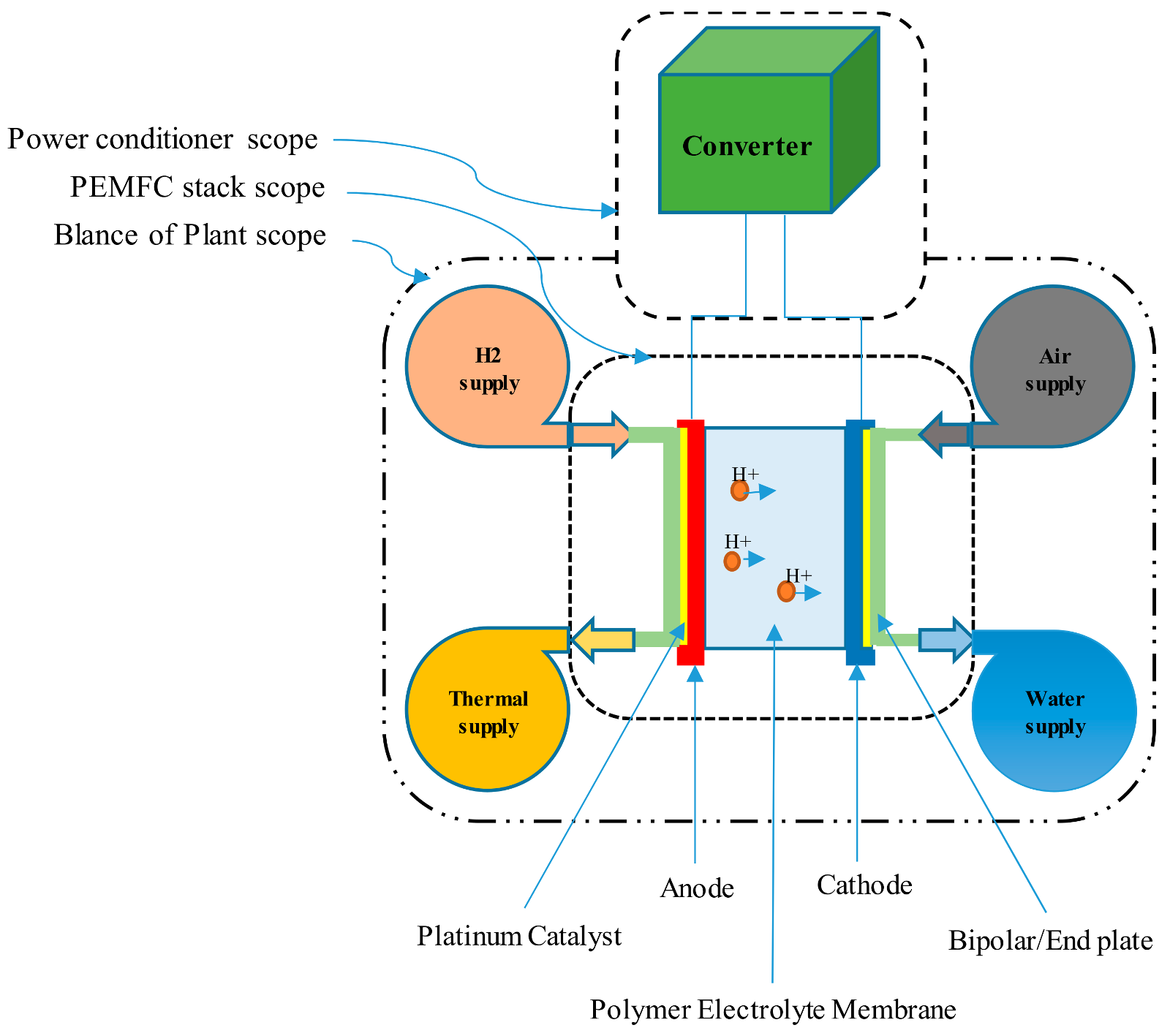
The oxidation reaction (2) and the reduction reaction (3) completer the general readout reaction of the PEMFC. The main subsystems of a PEMFC system for the electricity production (PEMFC stack) and the transfer of H+ are illustrated in Figure 1.
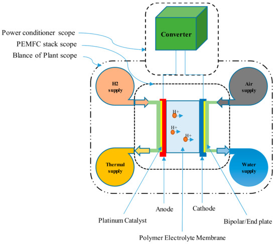
Figure 1.
Proton Exchange Membrane Fuel Cell (PEMFC) system overview with the scope to describe main subsystems and main components of the stack.
The cells are stacked in series to get desired amount of energy. On the other hand, because the PEMFC generates power in the range of a Watt to hundreds of Megawatts, they can be used in almost any application, from stationary power to vehicles of all sizes, such as marine power systems on naval ships, with the level of power 100 kW–1 MW [3].
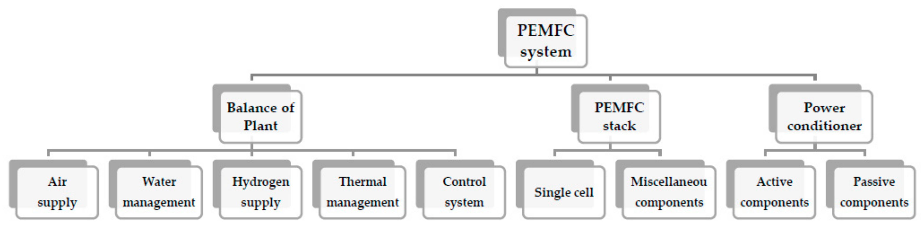
Figure 2 illustrates the PEMFC system main subsystems and components, which are essential in the forthcoming analysis in the next sections. Generally, the system contains three subsystems and nine components and 38 parts that are all listed in Table 1. The Balance-of-Plant (BoP), the PEMFC stack, and the power conditioner are three main subsystems of the PEMFC system. The BoP, which itself is comprised of auxiliary parts, is an instrumented system witch serves to control, manage, and supply of the hydrogen, air, water, and the thermal condition of the PEMFC stack. The PEMFC stack is an assembly of a number of single cells, each of which producing less than 1 V, bipolar plates, cooling plates, end plates, bolts, and gaskets, which convert the chemical energy to the electricity. The power conditioner includes active and passive components and uses DC/DC converters to regulate the output from the PEMFC stack to a fixed DC voltage [1,2,3,4].
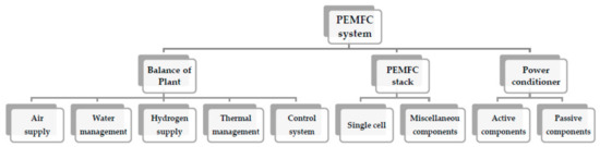
Figure 2.
Critical components of PEMFC main subsystems (i.e., Balance of Plant, PEMFC stack, and Power conditioner).

Table 1.
Parts, components, and subsystems present in a PEMFC system.
3. General Type-2 Fuzzy Systems
The following relations describe a GT2FS in a universal set [21,25]:
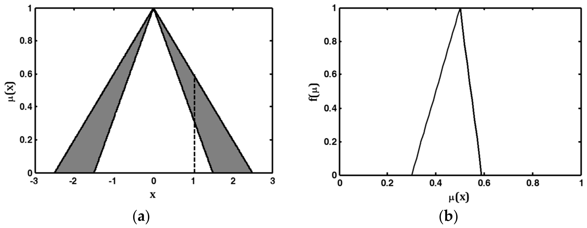
where and are the secondary fuzzy membership function, and secondary grade, respectively; is the primary membership and the domain of the secondary fuzzy membership function; and, is the fuzzy set varying in the interval [38]. Figure 3 illustrates a GT2FS in which the upper and lower fuzzy membership functions, as well as their secondary membership function, are chosen to be triangular.
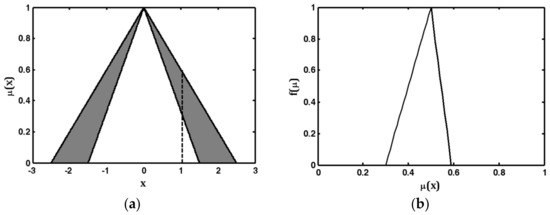
Figure 3.
A general type-2 fuzzy set with triangular upper and lower MFs where the secondary MF is triangular: (a): domain of the secondary membership function; (b): secondary membership function and secondary grade.
When , an interval type-2 fuzzy system (IT2FS), which shows a uniform uncertainty in the primary membership function, is obtained [19,30]. The IT2FS can be described based on its lower and upper fuzzy membership functions. Thanks to the computation simplicity of the type reduction, many researchers are persuaded to employ the IT2FSs instead of the GT2FSs [39]. However, Liu [35] introduced a GT2FSs new representation method, which benefits the low computation and effective performance and is preferable for both theoretical and computational viewpoints. This method is similar to the α-cut for type-1 fuzzy sets and is known as the -plane for type-2 fuzzy sets. A -plane representation for a GT2FS , denoted by , is the union of all the primary fuzzy membership functions with secondary grades greater than or equal to the special value :
The -plane-based GT2FS is expressed by
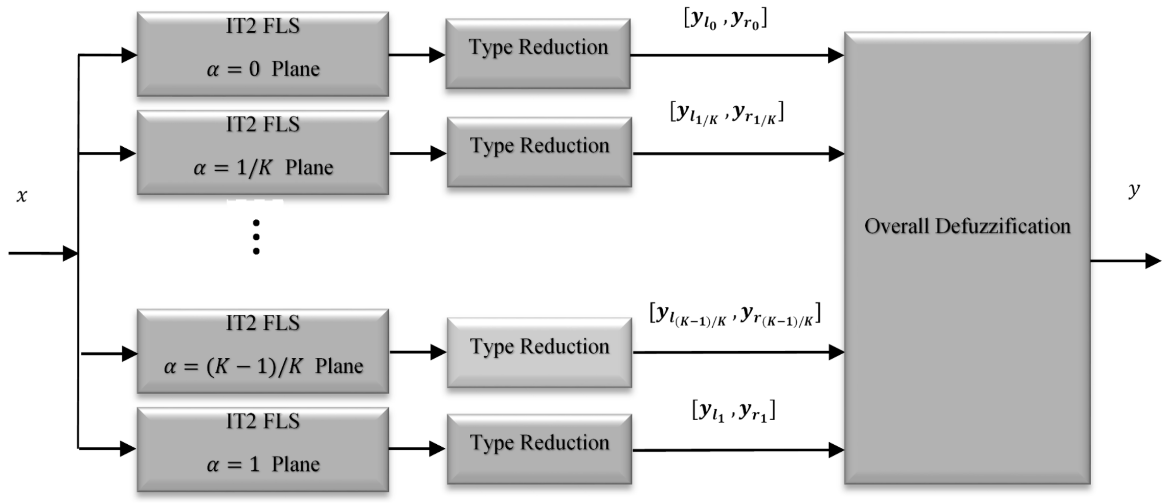
The representation (9) is very fruitful; since can be considered as an IT2FS with the second grade of the level . A GT2FS can be decomposed into several IT2FSs, each of which corresponds to a specific level of satisfying . Therefore, a GT2FS can be regarded as a collection of a high number of IT2FLSs. Meanwhile, Liu [10] used only 5 to 10 -planes and demonstrated that the required accuracy of centroid calculation is achieved. The new architecture for the GT2FS based on the -plane representation is illustrated in Figure 4 [23].

Figure 4.
Architecture for a general type-2 fuzzy Logic system.
The overall GT2FLS is constructed by a fuzzifier, a fuzzy rule-base, a fuzzy inference engine, a type reducer, and a defuzzifier. In this paper, the singleton fuzzifier is used to convert real crisp values into the fuzzy sets. The resulting output is a single point of a unity membership grade. The fuzzy rule base contains a finite number of IF-THEN fuzzy rules that are introduced by the experts. The jth rule of the GT2FLS is of the form:
where xi (i = 1,2, …, n) and y are the inputs and outputs of the GT2FS, respectively; and are antecedent and the consequent sets of the jth rule, respectively. The inference engine uses the fuzzy rule base to provide a nonlinear transformation from the GT2FS input to the output. For the α-plane representation, the fuzzy sets of each IT2FS are fired as:
where and are the lower and upper membership functions in the jth rule of the level , respectively, and × denotes the product t-norm. The output of the inference engine is a type-2 fuzzy set. Therefore, a type reducer is employed to reduce such type-2 fuzzy sets into a type-1 one [36]. The type reducer output in the IT2FS is characterized by its left-end and right-end points yl and yr, respectively. To compute these two endpoints, the KM iterative algorithms can be considered [36]. Among the type reduction methods, the center-of-sets (COS) is widely used, because it can be computed easily by the KM iterative algorithm [37]. By considering the singleton fuzzifier, the product t-norm in the inference engine and the COS type reducer, the left and right endpoints of the GT2FS is obtained by
and
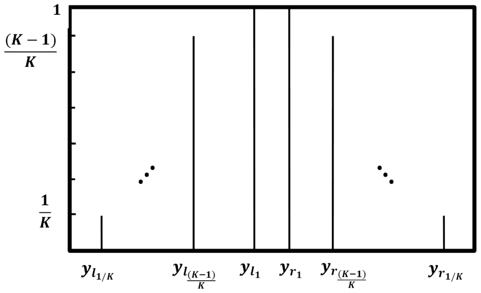
where is the left-endpoint of jth rule set with the level α, , , and . In addition, is the right endpoint of jth consequent set with level of α, , , and . In addition, R and L can be computed by employing the KM iterative algorithm for each of individual IT2FLSs with level α. Then, all of the intervals are merged into a type-1 fuzzy set, as shown in Figure 5. Finally, a crisp output is calculated through a centroid defuzzification as [25]:
where K + 1 shows the number of the α-planes or in other words, it determines the number of individuals.
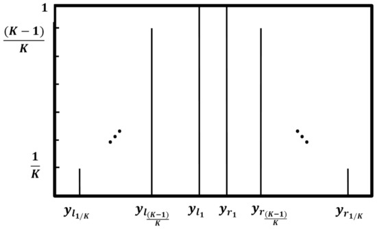
Figure 5.
Output of each individual IT2FLSs.
4. Failure Mode and Effect Analysis (FMEA)
The procedure of detecting, evaluating, and estimating possible failure in systems is known as the so-called FMEA. The FMEA is a proactive method, including qualitative and inductive approaches that avoid system faults before they happen [40]. The main objective of the FMEA is to enhance the design, test, control, and verification tasks. It is preferably used primarily in the development phase in order to determine key failure modes that can be designed out as early as possible. In the FMEA, instead of investigating the overall system through a top-to-down point of view, the individual components are analyzed by a down-to-top viewpoint [41].
Generally, three risk factors, including occurrence (), detectability (), and severity () are used in FMEA. The three input parameters are usually scored by 3, 5, and 10-point scale, depending on the case study and which standard that we use. For example, the standard MIL-STD-1629A was first developed in the US military that are used to classify different failures. It is the most commonly used standard used throughout the world for the past half a century [42]. Each failure is initially classified into three categories, which are further subcategorized.
Recently, 5-point scales for the risk factors has been attracting attention. Each grade scale gives a value from one to five and may have various ranges depending on the designers’ definition and the case study. Table 2, Table 3 and Table 4 show the classification options for the occurrence, detectability, and severity, respectively. The first classification is based on the occurrence of the failure. The more frequent a failure occurs, the more severe that it is. The Second category is on the basis of the detection of the failure. Moreover, the third category is dependent on the severity of a failure. For a bigger failure, the value of the severity is higher [11,43].
Table 2.
Occurrence Rating Scale [11].
Table 3.
Detection Rating Scale [11].
Table 4.
Severity Rating Scale [11].
It should be noted that the classification of the occurrence, detectability, and severity is completely case dependent. In other words, the descriptions in Table 2, Table 3 and Table 4 vary for different case studies. This paper uses the same standard as [11] for the application of a PEMFC in a marine power system.
The result of the FMEA is the risk priority number (RPN), which is mainly computed by the multiplication of the mentioned three factors. The RPN of each component shows the criticality of the failure effect of the associated component on the system continuity. These results comfort specialists to identify failures and their causes and address an agreed-upon percentage of total issues [44,45,46]. It should focus on the higher RPNs and reduce them by adding suitable safeguards or altering the system design.
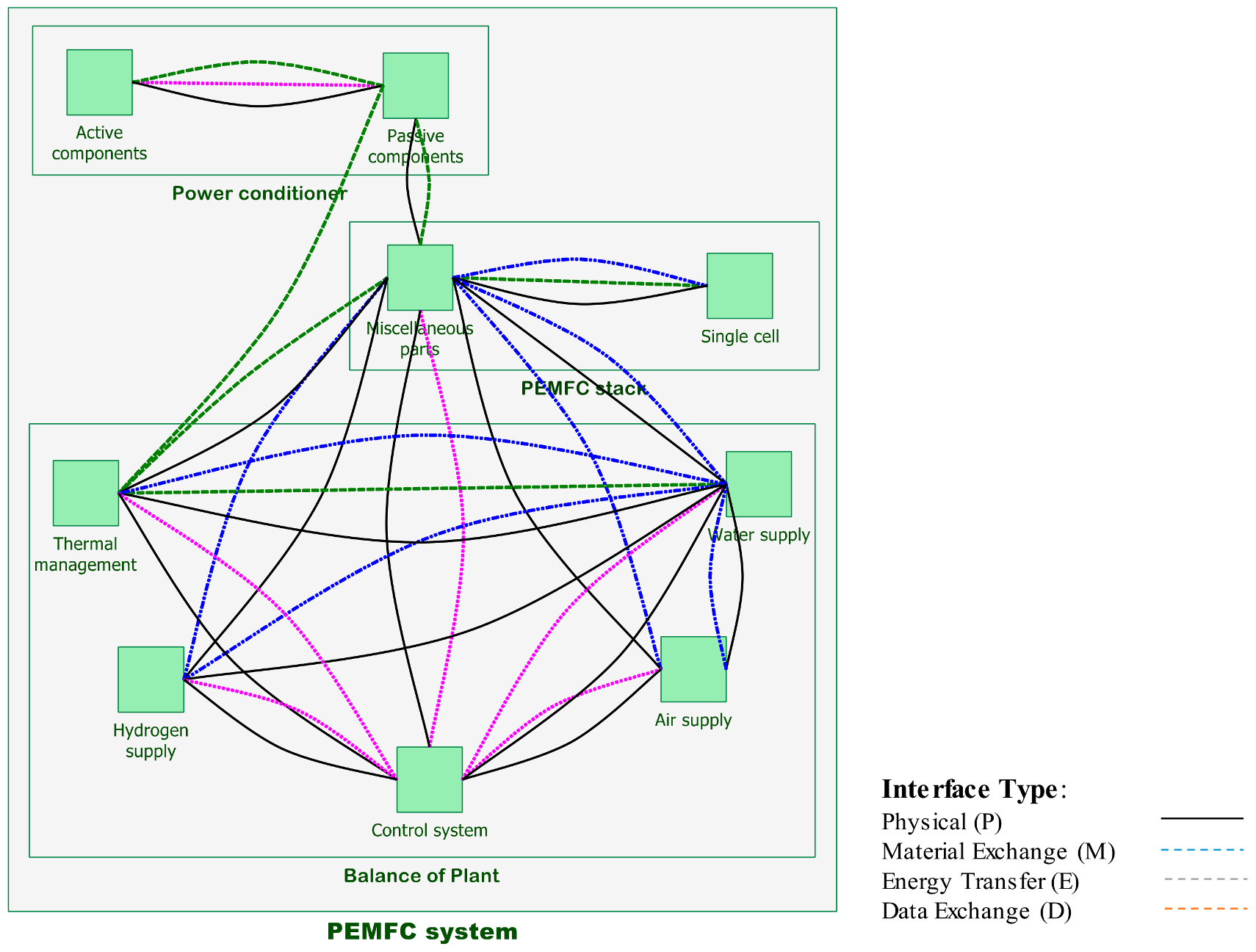
In practice, many failures degrade the power production of the PEMFC and the other generators and its transition to the desired load. Usually, more than half of all failure modes of a system occur at its interfaces. So, it is vital that an FMEA precisely investigates the connective links among the system subsystems and components, as well as their content [42]. In this regard, an FMEA block diagram is used to visually demonstrate the connecting links between the various subsystems and components. The FMEA interface matrix, which is a chart comprising vertical and horizontal axes, shows the kind of interface and determines which of them must be investigated through the examination. A material exchange, physical connection, energy transfer, and data exchange are four major kinds of interfaces. Table 5 demonstrates the FMEA interface matrix for the significant components of a PEMFC system, and the FMEA block diagram is illustrated in Figure 6.
Table 5.
FMEA interface matrix for components of PEMFC system.

Figure 6.
Failure modes and effects analysis (FMEA) block diagram for the main components of a PEMFC system.
General Type-II Fuzzy Based Failure Mode and Effect Analysis
The designer’s experiences highly influence the conventional FMEA of a new system, so that different multidisciplinary experts may provide different a RPN and make different decisions for an identical failure mode [47]. However, because of the practical imprecision and uncertainty, conventional FMEA techniques lead to low reliability and inaccurate results [48]. Recently, fuzzy type-1 logic techniques are considered for the FMEA [11] to improve the conventional results. However, these techniques still may lead to inaccurate results due to their inherent sensitivity with respect to the uncertainty. However, the fuzzy type-II logic is a good alternative to handle such inaccuracies and uncertainties and to establish a better risk picture of the propulsion marine system, which has not been experienced. The proposed technique uses fuzzy theory to determine an RPN for each failure mode. The conventional FMEA has several drawbacks, including the outcome of an identical RPN for different rating scales may lead to and ignoring some causative factors in the RPN computation procedure. Meanwhile, the fuzzy type-2 modeling overcomes such restrictions. The fuzzy-based FMEA approach employs linguistic descriptions of all potential failure modes. Three rating scales likelihood, severity, and detection, which were rated in Table 2, Table 3 and Table 4, are considered as the system input and fuzzified. Also, the RPN is the system output and is divided into five membership functions “very small”, “small”, “moderate”, “high”, and “very high”. Based on the inputs rates and the output membership functions, 125 IF-THEN fuzzy rules are introduced in the fuzzy inference. For example, the fuzzy implication rules are as follows:
- IF “likelihood is improbable” & “severity is minor” & “detectability is very high”, THEN “RPN is very small”.
- IF “likelihood is occasional” & “severity is major” & “detectability is remote”, THEN “RPN is medium”.
- IF “likelihood is frequent” & “severity is major” & “detectability is never”, THEN “RPN is high”.
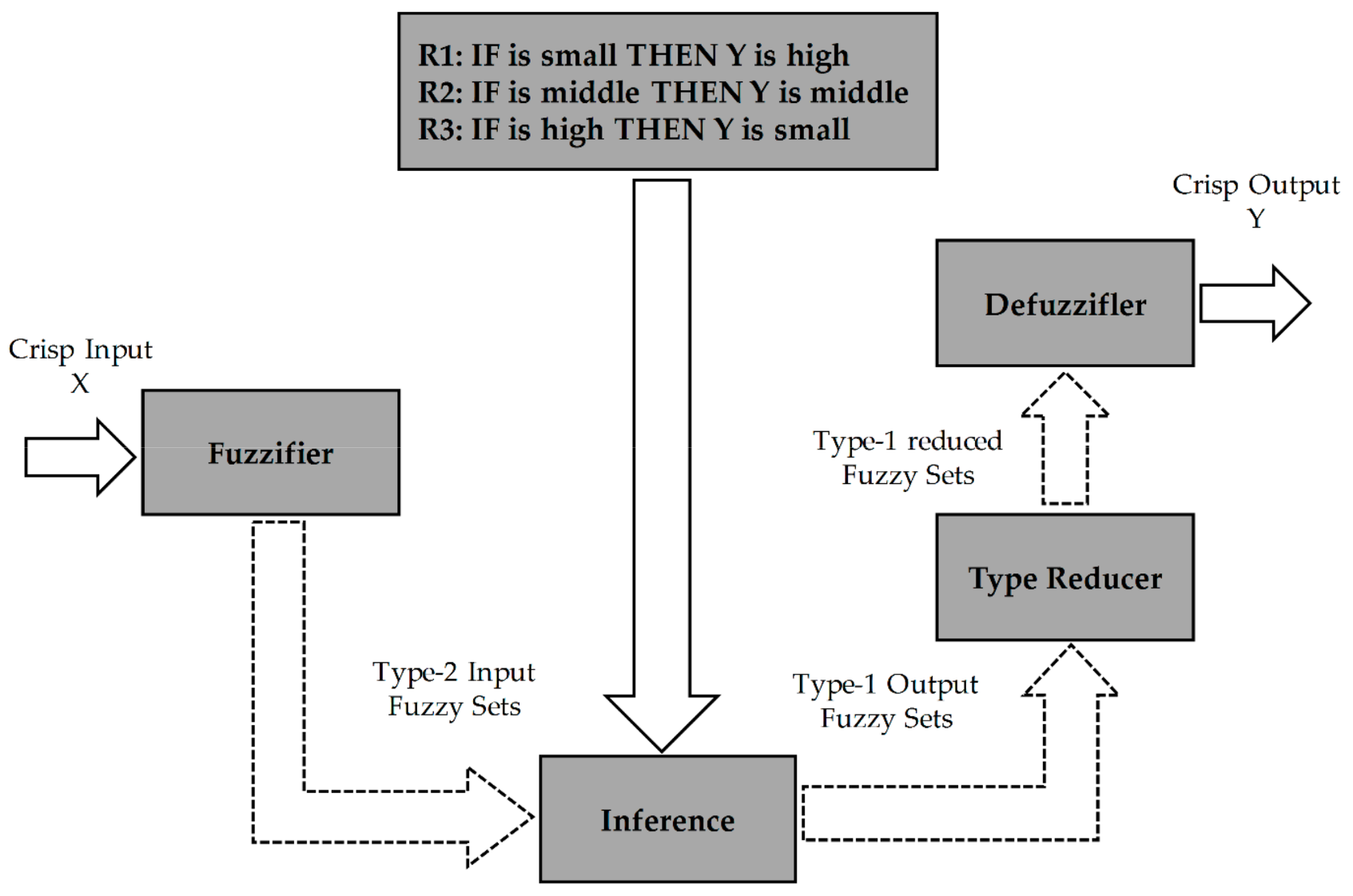
The overall proposed approach for computing the output RPN form the inputs occurrence, detectability, and severity is shown in Figure 7. As demonstrated in Figure 7, first the crisp inputs are fuzzified to obtain fuzzy type-2 input set. Then, such fuzzy sets are applied to the fuzzy interface engine to provide the fuzzy type-2 output set. Finally, by considering a type reducer and defuzzification, a crisp RPN is computed.
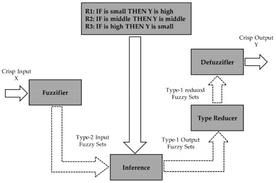
Figure 7.
The proposed fuzzy type-2 scheme for the FMEA.
5. Results and Discussion
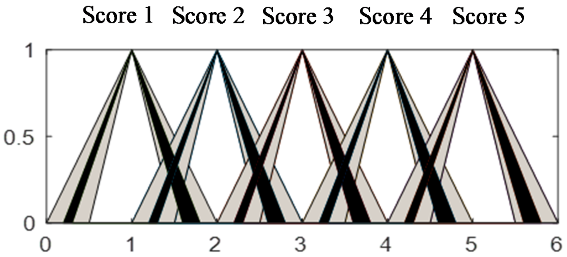
Fuzzy-based FMEA is conducted by the five-rating-scales as their fuzzy membership functions parameters are given in Figure 8. Furthermore, the output membership functions are plotted in Figure 9.
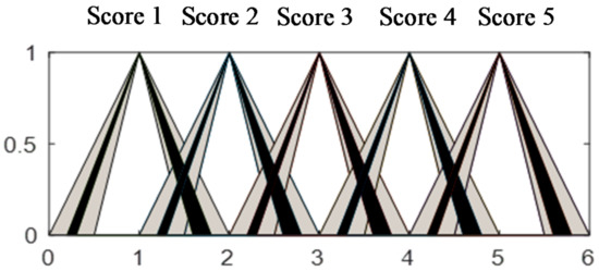
Figure 8.
The fuzzy type-2 memberships of the likelihood, severity, and detectability.
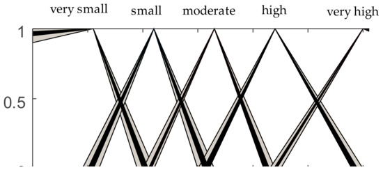
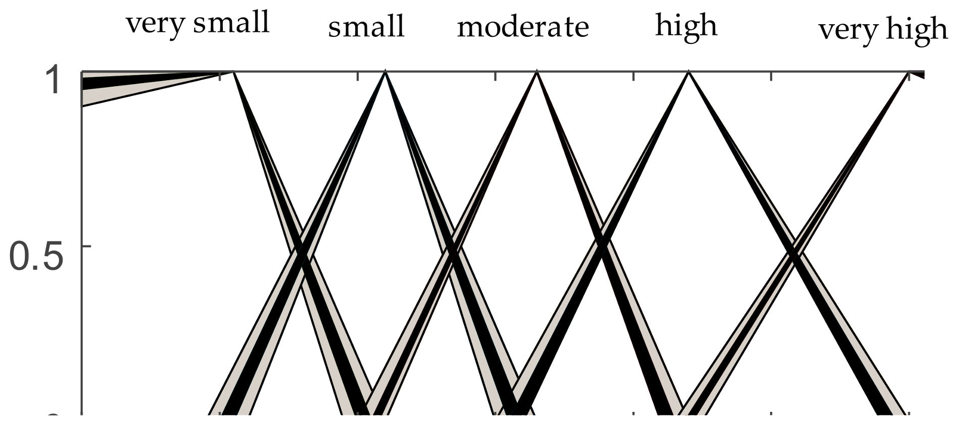
Figure 9.
The fuzzy membership functions of risk priority number (RPN).
This paper presents a new approach to estimate the PEMFC installed in a ship system. The PEMFC system has three main subsystems (Balance of Plant, PEMFC stack, Power conditioner), which consists of nine components and 38 parts, which are shown in Table 6, in which the conventional RPN and fuzzy type-1 and -2 RPNs are demonstrated. The analysis investigates more than 90 potential failure modes according to the API 580 (American Petroleum Institute), JEDEC (Joint Electron Device Engineering Council), NDI (Non-Destructive Inspection), and normal cause and failure in the industry standards. Actually, each failure mechanism causes a failure mode and a Failure mode is the procedure by which a failure with at least one case is observed.
Table 6.
FMEA results with calculated RPNs for PEMFC system.
Table 6 indicates that the proposed approach can better distinguish between the failure modes. For instance, the failure modes related to the water supply and active electrical components are obtained equal based on the conventional RPN and fuzzy type-1 approaches. Though, their occurrence (), detectability (), and severity (S) differs. Meanwhile, the proposed fuzzy type-2 method results in different RPN values for these two failure modes. Since the fuzzy type-2 employs a more complex structure for the fuzzy membership functions than type-1, one can expect small differences in the risk factors (i.e., occurrence, detectability, and severity) can better be sensed by the proposed approach and result in different RPNs, which provides a more accurate plan to remove or decrease those failure modes with the high risk and enhances the durability of the overall system operation. This is one of the main advantages of the proposed approach to the state-of-the-art methods that are unable to differentiate failures with roughly the same factors.
The highest RPN occurs in the control system that are considered as a monitoring, steering, and controls all of the systems and after that single cell, thermal management, and passive components, respectively. The FMEA produced the criticality of failure modes as relative predominance for more attention. There is some medium priority causes critical failures, such as excessive heat, overloading, and so on. Also, low priority causes with more types of critical failure, such as oxidation, humidity, and so on, which some of them cause system serious damage.
The PEMFC stack module will fail to generate electric power due to many failure modes that the 10 most significant of them is: overheating, leakage, fractured, extruded, stress corrosion cracking, erosion, deposits, cavitation, inadequate structural support, and fails to function as intended. Even if the severity is comparatively high, the detectability compensates for failure; thus, the estimated RPN is low. The highest RPN relatively more occurs in the PEMFC stack. This result illustrates that the mechanical failures of the PEMFC stack effectively influence the system functionality and are seldom (or maybe not) observable. The thermal management component is also one critical component. Because management of the fuel cell stack and power conditioner temperature function are very important for the safety and operation of the system. Fan, coolant pump, condenser, thermal connectors, anode cooler, and radiator, are the base of items in this component. Control system for this kind of device is very important and critical. In other words, because the monitoring and control utilities explicitly identify any failure mode, failures have relatively low RPNs and the overall stability increases.
Results from the proposed study indicate that, although the classic FMEA is an appropriate method for obtaining RPN, it assumes that S, O, and D parameters are equally important in calculating the RPN. However, in practice, the importance of these parameters differs and must be considered in the calculation procedure. These parameters basically come from qualitative numbers, which are usually obtained by expert judgments. Although the fuzzy type-1 tries to address this property, there still are some cases that are not distinguished by the fuzzy type-1. This drawback can be effectively decreased by employing the fuzzy type-2. This improvement is reasonable in the risk analysis. Because the goal of the risk analysis is to determine which phenomena have a higher risk and attempt to alleviate that. By employing the proposed approach, the differences in the RPN numbers can be better highlighted and one can simply find the failure mode with higher RPN. Meanwhile, by the conventional approach or the type-1 fuzzy, the roughly same failure modes results from an exact RPN value and one cannot evaluate which phenomena have a higher risk.
According to Table 6, for the items “Water supply/management” and “Active electrical components”, the conventional approach results RPN = 6 and the type-1 computes RPN = 14. However, it can be seen that the fuzzy type-2 computes two different values of 15.5 and 16.2, respectively. Consequently, the active electrical components item with RPN = 16.2 is more vital to have the higher risk than the water supply/management item with RPN = 15.5 in the PEMFC system. The same conclusion can be understood from the items “Thermal supply/management” and “Passive electrical components”.
6. Conclusions
This study has proposed an FMEA and a new general type-2 fuzzy structure well line for the PEMFC in a marine power system. The considered GT2FS was decomposed into multiple interval type-2 fuzzy logic systems with a pre-defined level of α for each to reduce the inherent highly computational burden of the general type-2 fuzzy systems. By considering the occurrence, detectability, and severity factors, which are categorized specifically for the PEMFC of the marine system, as the fuzzy linguistic inputs, a novel robust and effective method was proposed to compute the PRN. The obtained results have illustrated the advantages of the proposed approach over state-of-the-art techniques. Specifically, different RPNs are achieved for several failure modes with roughly equal risk factors, which the proposed approach, can be better highlighted the differences in the RPN numbers and it can simply find the failure mode with a higher RPN. For the future work, when considering a detailed FMEA to address the effect of marine motion on the subsystems and the components that are involved in the FMEA is an important research area.
Author Contributions
The main idea for the paper was proposed by Sajjad Bahrebar, and he wrote the first draft of the paper. Sajjad Bahrebar, Navid Vafamand and Sima Rastayesh has developed the concept of the original proposal and designed, performed the real time implementation. Frede Blaabjerg and Huai Wang provided the guidelines for theoretical validation in line with the developed theoretical background. Sima Rastayesh, Mohammad-Hassan Khooban and Dao Zhou provided the support for technical validation for the mathematical background and validation with results. Frede Blaabjerg, Huai Wang, Dao Zhou, Mohammad-Hassan Khooban and Sima Rastayesh thoroughly reviewed the paper. All authors contributed for articulate the research work in its current form as full research manuscript.
Conflicts of Interest
The authors declare no conflict of interest.
References
- Yuan, X.Z.; Li, H.; Zhang, S.; Martin, J.; Wang, H. A review of polymer electrolyte membrane fuel cell durability test protocols. J. Power Sources 2011, 196, 9107–9116. [Google Scholar] [CrossRef]
- Barbir, F. PEM Fuel Cells: Theory and Practice; Academic Press: Cambridge, MA, USA, 2013; ISBN 9780123877109. [Google Scholar]
- Zhang, J. PEM Fuel Cell Electrocatalysts and Catalyst Layers: Fundamentals and Applications; Springer: Berlin, Germany, 2008; ISBN 9781848009356. [Google Scholar]
- Zhang, J.; Zhang, H.; Wu, J.; Zhang, J. PEM Fuel Cell Testing and Diagnosis; Elsevier: Amsterdam, The Netherlands, 2013; ISBN 9780444536884. [Google Scholar]
- Jayakumar, A.; Sethu, S.P.; Ramos, M.; Robertson, J.; Al-Jumaily, A. A technical review on gas diffusion, mechanism and medium of PEM fuel cell. Ionics (Kiel) 2015, 21, 1–18. [Google Scholar] [CrossRef]
- Zhou, D.; Wang, H.; Blaabjerg, F.; Kær, S.K.; Blom-hansen, D. System-level Reliability Assessment of Power Stage in Fuel Cell Application. In Proceedings of the 2016 IEEE Energy Conversion Congress and Exposition (ECCE), Milwaukee, WI, USA, 18–22 September 2016. [Google Scholar]
- Lee, S.; Zhou, D.; Wang, H. Reliablity assessment of fuel cell system—A framework for quantitative approach. In Proceedings of the 2016 IEEE Energy Conversion Congress and Exposition (ECCE), Milwaukee, WI, USA, 18–22 September 2016. [Google Scholar] [CrossRef]
- Ma, K.; Wang, H.; Blaabjerg, F. New approaches to reliability assessment: Using physics-of-failure for prediction and design in power electronics systems. IEEE Power Electron. Mag. 2016, 3, 28–41. [Google Scholar] [CrossRef]
- Huai, W.; Liserre, M.; Blaabjerg, F.; De Place Rimmen, P.; Jacobsen, J.B.; Kvisgaard, T.; Landkildehus, J. Transitioning to physics-of-failure as a reliability driver in power electronics. IEEE J. Emerg. Sel. Top. Power Electron. 2014, 2, 97–114. [Google Scholar] [CrossRef]
- Rafie, M.; Samimi Namin, F. Prediction of subsidence risk by FMEA using artificial neural network and fuzzy inference system. Int. J. Min. Sci. Technol. 2015, 25, 655–663. [Google Scholar] [CrossRef]
- Ahn, J.; Noh, Y.; Park, S.H.; Choi, B., II; Chang, D. Fuzzy-based failure mode and effect analysis (FMEA) of a hybrid molten carbonate fuel cell (MCFC) and gas turbine system for marine propulsion. J. Power Sources 2017, 364, 226–233. [Google Scholar] [CrossRef]
- Casson Moreno, V.; Cozzani, V. Integrated hazard identification within the risk management of industrial biological processes. Saf. Sci. 2018, 103, 340–351. [Google Scholar] [CrossRef]
- Dunjó, J.; Fthenakis, V.; Vílchez, J.A.; Arnaldos, J. Hazard and operability (HAZOP) analysis. A literature review. J. Hazard. Mater. 2010, 173, 19–32. [Google Scholar] [CrossRef] [PubMed]
- Kang, J.; Sun, L.; Sun, H.; Wu, C. Risk assessment of floating offshore wind turbine based on correlation-FMEA. Ocean Eng. 2017, 129, 382–388. [Google Scholar] [CrossRef]
- Gerbec, M.; Jovan, V.; Petrovčič, J. Operational and safety analyses of a commercial PEMFC system. Int. J. Hydrog. Energy 2008, 33, 4147–4160. [Google Scholar] [CrossRef]
- Jayakumar, A.; Ramos, M.; Al-Jumaily, A. A Novel Fuzzy Schema to Control the Temperature and Humidification of PEM Fuel Cell System. In Proceedings of the ASME 2015 13th International Conference on Fuel Cell Science, Engineering and Technology, San Diego, CA, USA, 28 June–2 July 2015; p. V001T06A005. [Google Scholar]
- Hora, S.C. Aleatory and epistemic uncertainty in probability elicitation with an example from hazardous waste management. Reliab. Eng. Syst. Saf. 1996, 54, 217–223. [Google Scholar] [CrossRef]
- Zadeh, L.A. The concept of a linguistic variable and its application to approximate reasoning—I. Inf. Sci. 1975, 8, 199–249. [Google Scholar] [CrossRef]
- Khooban, M.H.; Liaghat, A. A time-varying strategy for urban traffic network control: A fuzzy logic control based on an improved black hole algorithm. Int. J. Bio-Inspired Comput. 2017, 10, 33–42. [Google Scholar] [CrossRef]
- Khooban, M.H.; Niknam, T.; Sha-Sadeghi, M. A time-varying general type-II fuzzy sliding mode controller for a class of nonlinear power systems. J. Intell. Fuzzy Syst. 2016, 30, 2927–2937. [Google Scholar] [CrossRef]
- Khooban, M.H.; Niknam, T.; Sha-Sadeghi, M. Speed control of electrical vehicles: A time-varying proportional–integral controller-based type-2 fuzzy logic. IET Sci. Meas. Technol. 2016, 10, 185–192. [Google Scholar] [CrossRef]
- Khooban, M.H.; Vafamand, N.; Liaghat, A.; Dragicevic, T. An optimal general type-2 fuzzy controller for Urban Traffic Network. ISA Trans. 2017, 66, 335–343. [Google Scholar] [CrossRef] [PubMed]
- Tavana, M.R.; Khooban, M.-H.; Niknam, T. Adaptive PI controller to voltage regulation in power systems: STATCOM as a case study. ISA Trans. 2017, 66, 325–334. [Google Scholar] [CrossRef] [PubMed]
- Khooban, M.H.; Niknam, T. A new and robust control strategy for a class of nonlinear power systems: Adaptive general type-II fuzzy. Proc. Inst. Mech. Eng. Part I J. Syst. Control Eng. 2015, 229, 517–528. [Google Scholar] [CrossRef]
- Khooban, M.H.; Ghaemi, M.; Hosseini-Sani, S.K. Direct adaptive general type-2 fuzzy control for a class of uncertain non-linear systems. IET Sci. Meas. Technol. 2014, 8, 518–527. [Google Scholar] [CrossRef]
- Khooban, M.-H.; Niknam, T.; Shasadeghi, M.; Dragicevic, T.; Blaabjerg, F. Load Frequency Control in Microgrids Based on a Stochastic Non-Integer Controller. IEEE Trans. Sustain. Energy 2017, 9, 853–861. [Google Scholar] [CrossRef]
- Khooban, M.-H.; Dragicevic, T.; Blaabjerg, F.; Delimar, M. Shipboard Microgrids: A Novel Approach to Load Frequency Control. IEEE Trans. Sustain. Energy 2017, 9, 843–852. [Google Scholar] [CrossRef]
- Khooban, M.H.; ShaSadeghi, M.; Niknam, T.; Blaabjerg, F. Analysis, control and design of speed control of electric vehicles delayed model: Multi-objective fuzzy fractional-order P I λ D μ controller. IET Sci. Meas. Technol. 2017, 11, 249–261. [Google Scholar] [CrossRef]
- Abadi, D.N.M.; Khooban, M.H. Design of optimal Mamdani-type fuzzy controller for nonholonomic wheeled mobile robots. J. King Saud Univ. Eng. Sci. 2015, 27, 92–100. [Google Scholar] [CrossRef]
- Khooban, M.H.; Niknam, T.; Dehghani, M.; Blaabjerg, F. Free chattering hybrid sliding mode control for a class of non-linear systems: Electric vehicles as a case study. IET Sci. Meas. Technol. 2016, 10, 776–785. [Google Scholar] [CrossRef]
- Khooban, M.H.; Vafamand, N.; Niknam, T. T–S fuzzy model predictive speed control of electrical vehicles. ISA Trans. 2016, 64, 231–240. [Google Scholar] [CrossRef] [PubMed]
- Khooban, M.H.; Niknam, T.; Blaabjerg, F.; Dragičević, T. A new load frequency control strategy for micro-grids with considering electrical vehicles. Electr. Power Syst. Res. 2017, 143, 585–598. [Google Scholar] [CrossRef]
- Niknam, T.; Khooban, M.H. Fuzzy sliding mode control scheme for a class of non-linear uncertain chaotic systems. IET Sci. Meas. Technol. 2013, 7, 249–255. [Google Scholar] [CrossRef]
- Niknam, T.; Khooban, M.H.; Kavousifard, A.; Soltanpour, M.R. An optimal type II fuzzy sliding mode control design for a class of nonlinear systems. Nonlinear Dyn. 2014, 75, 73–83. [Google Scholar] [CrossRef]
- Liu, F. An efficient centroid type-reduction strategy for general type-2 fuzzy logic system. Inf. Sci. 2008, 178, 2224–2236. [Google Scholar] [CrossRef]
- Karnik, N.N.; Mendel, J.M. Type-2 fuzzy logic systems: Type-reduction. In SMC’98 Conference Proceedings, Proceedings of the 1998 IEEE International Conference on Systems, Man, and Cybernetics, San Diego, CA, USA, 14 October 1998; Cat. No. 98CH36218; IEEE: Piscataway, NJ, USA, 1998; Volume 2, pp. 2046–2051. [Google Scholar]
- Karnik, N.N.; Mendel, J.M. Centroid of a type-2 fuzzy set. Inf. Sci. 2001, 132, 195–220. [Google Scholar] [CrossRef]
- Mendel, J.M.; Feilong, L.; Daoyuan, Z. α-Plane Representation for Type-2 Fuzzy Sets: Theory and Applications. IEEE Trans. Fuzzy Syst. 2009, 17, 1189–1207. [Google Scholar] [CrossRef]
- Feili, H.R.; Akar, N.; Lotfizadeh, H.; Bairampour, M.; Nasiri, S. Risk analysis of geothermal power plants using Failure Modes and Effects Analysis (FMEA) technique. Energy Convers. Manag. 2013, 72, 69–76. [Google Scholar] [CrossRef]
- Colli, A. Failure mode and effect analysis for photovoltaic systems. Renew. Sustain. Energy Rev. 2015, 50, 804–809. [Google Scholar] [CrossRef]
- Narayanagounder, S.; Gurusami, K. A New Approach for Prioritization of Failure Modes in Design FMEA using ANOVA. World Acad. Sci. Eng. Technol. 2009, 3, 524–531. [Google Scholar]
- Carlson, C. Effective FMEAs: Achieving Safe, Reliable, and Economical Products and Processes Using Failure Mode and Effects Analysis; John Wiley & Sons: Hoboken, NJ, USA, 2012. [Google Scholar]
- Fattahi, R.; Khalilzadeh, M. Risk evaluation using a novel hybrid method based on FMEA, extended MULTIMOORA, and AHP methods under fuzzy environment. Saf. Sci. 2018, 102, 290–300. [Google Scholar] [CrossRef]
- Mao, L.; Jackson, L.; Davies, B. Investigation of PEMFC fault diagnosis with consideration of sensor reliability. Int. J. Hydrogen Energy 2017. [Google Scholar] [CrossRef]
- Mao, L.; Jackson, L.; Dunnett, S. Fault Diagnosis of Practical Polymer Electrolyte Membrane (PEM) Fuel Cell System with Data-driven Approaches. Fuel Cells 2017, 17, 247–258. [Google Scholar] [CrossRef]
- Carlson, C.S. Effective FMEAs; John Wiley & Sons, Inc.: Hoboken, NJ, USA, 2012; ISBN 9781118312575. [Google Scholar]
- Adar, E.; İnce, M.; Karatop, B.; Bilgili, M.S. The risk analysis by failure mode and effect analysis (FMEA) and fuzzy-FMEA of supercritical water gasification system used in the sewage sludge treatment. J. Environ. Chem. Eng. 2017, 5, 1261–1268. [Google Scholar] [CrossRef]
- Dağsuyu, C.; Göçmen, E.; Narlı, M.; Kokangül, A. Classical and fuzzy FMEA risk analysis in a sterilization unit. Comput. Ind. Eng. 2016, 101, 286–294. [Google Scholar] [CrossRef]
© 2018 by the authors. Licensee MDPI, Basel, Switzerland. This article is an open access article distributed under the terms and conditions of the Creative Commons Attribution (CC BY) license (http://creativecommons.org/licenses/by/4.0/).