Article

Development of Chelating Agent-Based Polymeric Gel System for Hydraulic Fracturing

by
Muhammad Shahzad Kamal
1,*,
Marwan Mohammed
2,
Mohamed Mahmoud
2 and
Salaheldin Elkatatny
2
1
Center for Integrative Petroleum Research, King Fahd University of Petroleum & Minerals, Dhahran 31261, Saudi Arabia
2
Department of Petroleum Engineering, King Fahd University of Petroleum & Minerals, Dhahran 31261, Saudi Arabia
*
Author to whom correspondence should be addressed.
Energies 2018, 11(7), 1663; https://doi.org/10.3390/en11071663
Submission received: 21 May 2018 / Revised: 2 June 2018 / Accepted: 4 June 2018 / Published: 26 June 2018
(This article belongs to the Special Issue Flow and Transport Properties of Unconventional Reservoirs 2018)

Abstract

:
Hydraulic Fracturing is considered to be one of the most important stimulation methods. Hydraulic Fracturing is carried out by inducing fractures in the formation to create conductive pathways for the flow of hydrocarbon. The pathways are kept open either by using proppant or by etching the fracture surface using acids. A typical fracturing fluid usually consists of a gelling agent (polymers), cross-linkers, buffers, clay stabilizers, gel stabilizers, biocide, surfactants, and breakers mixed with fresh water. The numerous additives are used to prevent damage resulting from such operations, or better yet, enhancing it beyond just the aim of a fracturing operation. This study introduces a new smart fracturing fluid system that can be either used for proppant fracturing (high pH) or acid fracturing (low pH) operations in sandstone formations. The fluid system consists of glutamic acid diacetic acid (GLDA) that can replace several additives, such as cross-linker, breaker, biocide, and clay stabilizer. GLDA is also a surface-active fluid that will reduce the interfacial tension eliminating the water-blockage effect. GLDA is compatible and stable with sea water, which is advantageous over the typical fracturing fluid. It is also stable in high temperature reservoirs (up to 300 °F) and it is also environmentally friendly and readily biodegradable. The new fracturing fluid formulation can withstand up to 300 °F of formation temperature and is stable for about 6 h under high shearing rates (511 s−1). The new fracturing fluid formulation breaks on its own and the delay time or the breaking time can be controlled with the concentrations of the constituents of the fluid (GLDA or polymer). Coreflooding experiments were conducted using Scioto and Berea sandstone cores to evaluate the effectiveness of the developed fluid. The flooding experiments were in reasonable conformance with the rheological properties of the developed fluid regarding the thickening and breaking time, as well as yielding high return permeability.

1. Introduction

Hydraulic fracturing and acid fracturing operations are currently considered as one of the most important stimulation methods in the oil and gas industry [1]. In acid fracturing, the acid is spent to create uneven etches (channels) in the rock (fracture face). In acid fracturing, the formation rock must contain minerals that are partially soluble in the acid used to create those etches. On the other hand, in hydraulic fracturing, single or multiple fractures are induced in the formation by injecting a high-pressure fluid to stimulate and enhance the producing wells. These fractures are then kept open using a proppant, thus preventing the closure of those fractures due to stresses that are acting on the formation. After the completion of the process, the injected fluids are broken into low viscosity liquids using breakers to enhance the flow back of the fluid to the surface [2,3,4,5].
Hydraulic Fracturing is prominent amongst permeability-impaired formations (low permeability reservoirs) i.e., shale-gas and tight-gas [6,7,8,9]. Hydraulic fracturing significantly improves the productivity of the wells and the overall recovery factor [10]. Hydraulic fracturing is also widely used in moderate permeability reservoirs (up to 50 mD for oil and 1 mD for gas) with the large skin around the vicinity of the wellbore by bypassing the damaged zone to further enhance the flow of hydrocarbon, allowing for accelerated production without negatively impacting the formation reserves. However, this case relies mostly on the economic feasibility of conducting such operations [11].
The fracturing fluid must be designed and tested carefully in order to avoid incompatibility with the formation. Especially, if the reservoir contains minerals that are water sensitive, such as clay minerals (smectite, illite) found in tight gas or shale gas reservoirs, which can cause fines migration or swelling that results in damaging the reservoir furthermore. Due to the large quantities of gas in those formations, any enhancement on their recovery is of great importance. Tight reservoirs are those reservoirs that are characterized by a low-permeability (i.e., less than 0.5 mD), they are either carbonate or sandstone reservoirs [12,13]. Problems that are associated with tight gas production in drilling or hydraulic fracturing operations include aqueous phase trapping, natural fractures (fluid leak-off), folding and faulting (making the prediction of fracture pressure difficult), and fluid incompatibility with the formation [14]. Water blockage or aqueous phase trapping (APT) is a serious problem in tight formations among others [15,16,17].
Several types of fracturing fluids have been used in oil & gas fields which include but not limited to linear polymer gel, viscoelastic surfactants, crosslinked polymer gels, and foam-based fracturing fluids [18,19,20,21,22,23,24,25,26,27]. Linear and crosslinked polymer fracturing fluids can achieve high viscosity, less fluid leak-off, and good proppant suspension capabilities for varying reservoir permeabilities. Polymer-based fracturing fluids are also thermally stable. At high pressure, filter cake formation further reduces the leak-off of fluids into the formation. However, high residue that is deposited within the fracture after the completion of fracturing process is a major disadvantage of the polymer-based fracturing fluid. Different types of breakers are used to break the viscosity after completion process. The viscoelastic surfactant-based fracturing fluid is thermodynamically stable and it causes less damage to the formation when compared to the polymer-based gel. However, the rheological properties of viscoelastic gels are severely affected by temperature, counterions, and surfactant concentration. The viscoelastic surfactant-based gels have more leak-off due to low molecular weight and absence of filter cake. Therefore, a fracturing fluid with better rheological properties, thermal stability, proppant suspension capability, and less leak-off is required.
In this work, we introduce a new smart fracturing fluid system that can be either used for proppant fracturing (high pH) or acid fracturing (low pH) operations in tight as well as conventional formations. The fluid system consists of glutamic acid diacetic acid (GLDA) that can replace cross-linker, breaker, biocide, and clay stabilizer from fracturing fluid formulation. GLDA could be manufactured in the form of sodium-GLDA or potassium-GLDA, and both sodium and potassium are considered as clay stabilizers. At the same time, GLDA at high pH is gentle to the clay minerals and does not break them like HCl [28,29]. Also, published literature showed that GLDA not only acts as a biocide, but also boosts the activity and efficiency of biocides as well [30,31]. GLDA is compatible and stable with both freshwater and seawater which is advantageous over other fracturing fluids. It is also stable in high-temperature reservoirs (up to 300 °F). GLDA (which is the main constituent of the newly proposed fracturing fluid) is a low-interfacial tension (IFT) fluid, which will reduce the IFT eliminating the APT. At low pH, GLDA reacts as an acid with the carbonate minerals in the formation producing CO2 as a by-product, and at high pH, it will react with the rocks creating a lower IFT fluid than the initial value, which makes the fluid in both pH ranges effective in reducing the APT effect. The new fluid system was tested and evaluated in low and high permeability sandstones core samples (Scioto and Berea). The fracturing fluid was tested with several polymers at several concentrations and pH ranges.

2. Experimental

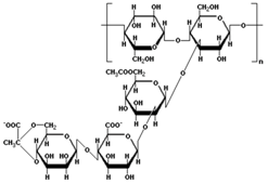
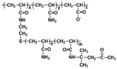
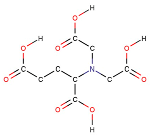
The fracturing fluid formulation was prepared by dissolving the polymer and chelating agent in fresh water. Five different polymers used are shown in Table 1. Partially hydrolyzed polyacrylamide (HPAM) and Copolymer of 2-acrylamido-2-methylpropane sulfonic acid and acrylamide (AMPS) were supplied by SNF FLOERGER, France [32,33,34,35,36]. Thermoviscofying polymer (TVP) was obtained from Hengju Polymer Co., Beijing, China. The structures of the chelating agents are given in Table 2. The GLDA was supplied by AkzoNobel, while other chelating agents were purchased from Sigma Aldrich (Saint Louis, MO, USA). Core sample characteristics and mineral compositions of core samples are given in Table 3 and Table 4, respectively. Thermogravimetric analysis (TGA) was carried out using SDT-Q600 (TA Instruments, New Castle, DE, USA) at a heating rate of 9 °F/min under a nitrogen flow rate of 20 cm3/min. Fourier Transform Infrared Spectroscopy (FTIR) of the solutions at a different pH was conducted using Bruker Tensor27 equipment (Bruker, Billerica, MA, USA). The rheological properties were determined using high temperature and high-pressure rheometer (Grace 5600, Grace Instrument Co., Houston, TX, USA).
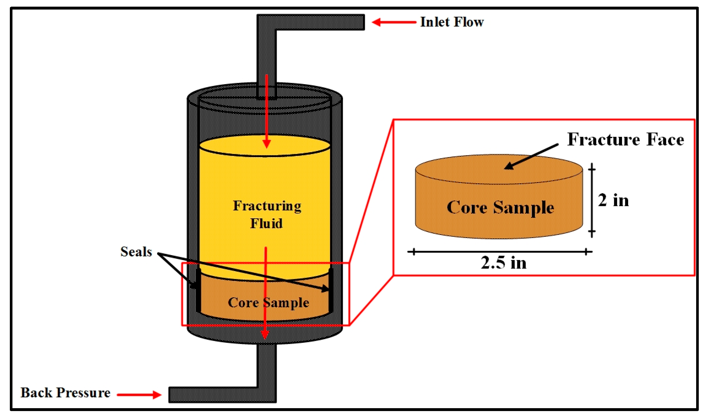
Two different sandstone cores with varying permeability (Table 3) were used in two coreflooding experiments. The cores were cut, polished, and the end faces were ground. The core samples were saturated with 3 wt % potassium chloride (brine water) to prevent damage occurring from clay minerals if contacted by fresh water. The preparations of core consisted of several steps. The cores were dried in an oven at 250 °F for 24 h. The dry cores were weighted and then saturated with brine under vacuum using a pump and a desiccator for 6 h. The saturated cores were weighted and the porosities of the cores were calculated. The permeabilities of the cores were calculated using Darcy’s law. The schematic diagram of coreflooding setup is shown in Figure 1. For Scioto sandstone core samples, 20 wt % GLDA at pH 12 and 45 pounds per thousand gallons (pptg) of AMPS polymer diluted in deionized (DI) water were prepared for the continuous pumping experiment. For Berea sandstone core sample, 20 wt % GLDA at pH 12 and 70 pptg of XC-Polymer diluted in DI water were prepared for the continuous pumping experiment. The following procedure was adopted for coreflooding experiments:
  • Fill the cell from the top with the fracturing fluid, and tighten the cell top and connect the pressure lines coming from the transfer cells (Figure 2).
  • Insert the core sample into the cell and tighten the cell bottom of the cell against the core sample to prevent leaking and attach the pressure lines leading to the back-pressure system.
  • Set the temperature to the required value and allow enough time for the core sample to be heated (about 1 h).
  • Apply the required pressure on the transfer cells, and open the valves leading to the core cell, and apply the required back pressure to the system, and open the valves leading to the core cell.
  • Using the water pump, the injection rate was set to the required value and activated to start flooding the core sample, the pressure drop was monitored with time until the required pore volumes were injected. Effluents from some intervals were collected for analysis.
The inlet pressure, back pressure, and temperature was 500 psi, 200 psi, and 300 °F, respectively, for both cores. The injection rate for Scioto sandstone core was 1 cm3/min and for the Berea sandstone core it was 20 cm3/min.

3. Results & Discussion

The results and discussion section is divided into four different sections. The first section deals with the thermal stability of polymers that were used in this study. The second section describes the rheological properties of different fracturing fluids. The third section represents the FTIR analysis of the fracturing fluid formulations. Finally, the coreflooding results of the selected formulation are given in the fourth section.

3.1. Thermal Stability

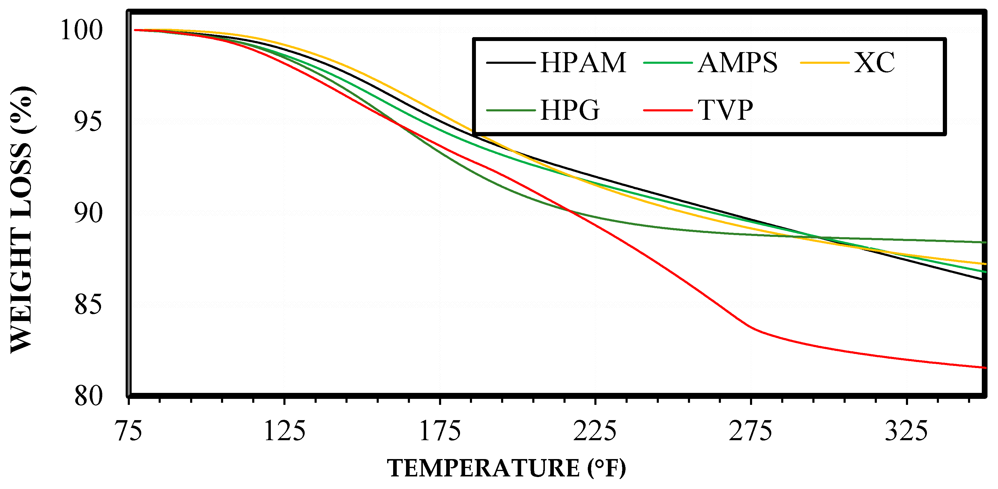
Five different water-soluble polymers from different classes were selected to develop the optimum fracturing fluid formulation using polymer-chelating agent solution. The details of these polymers are given in Table 1. In the first step, the thermal stability of all the polymers was investigated using the thermogravimetric analyzer. Thermogravimetric analysis (Figure 3) showed that HPG polymer had the lowest mass loss of all the tested polymers (11.63%), followed by XC polymer (12.83%), AMPS (13.3%), HPAM (13.8%), and TVP (18.5%). However, the overall tolerance of the five polymers was good when subjected to high temperatures, a 10% average of mass loss of those polymers can be attributed to the residual humidity in the polymer powder and that is indicated by the sharp decline in the mass loss in temperatures up to 212 °F. No severe polymer degradation was noticed in the five polymer samples, which indicates that the polymers are resistive when subjected to temperatures similar to reservoir conditions (up to 350 °F).

3.2. Rheological Properties

The fracturing fluid formulation was developed by evaluating three different chelating agents and five polymers. The performance of three different chelating agents (DTPA, GLDA, and EDTA) with xanthan gum was determined. The apparent viscosity of the xanthan polymer solution in deionized water was measured by adding three different chelating agents at a fixed concentration (20 wt %). The concentration of the polymer was fixed to 0.43 wt % (typical field concentration). Figure 4 shows the apparent viscosity of xanthan gum with three different chelating agents. All of the investigated chelating agents (DTPA, GLDA, and EDTA) exhibited a thickening effect, however, only GLDA experienced breaking behavior without the addition of breakers. Owing to a constant viscosity with time (no breaking), DTPA and EDTA were excluded from further testing. It is, however, worth mentioning that the DTPA and EDTA can be used if a breaker is to be introduced to the system.
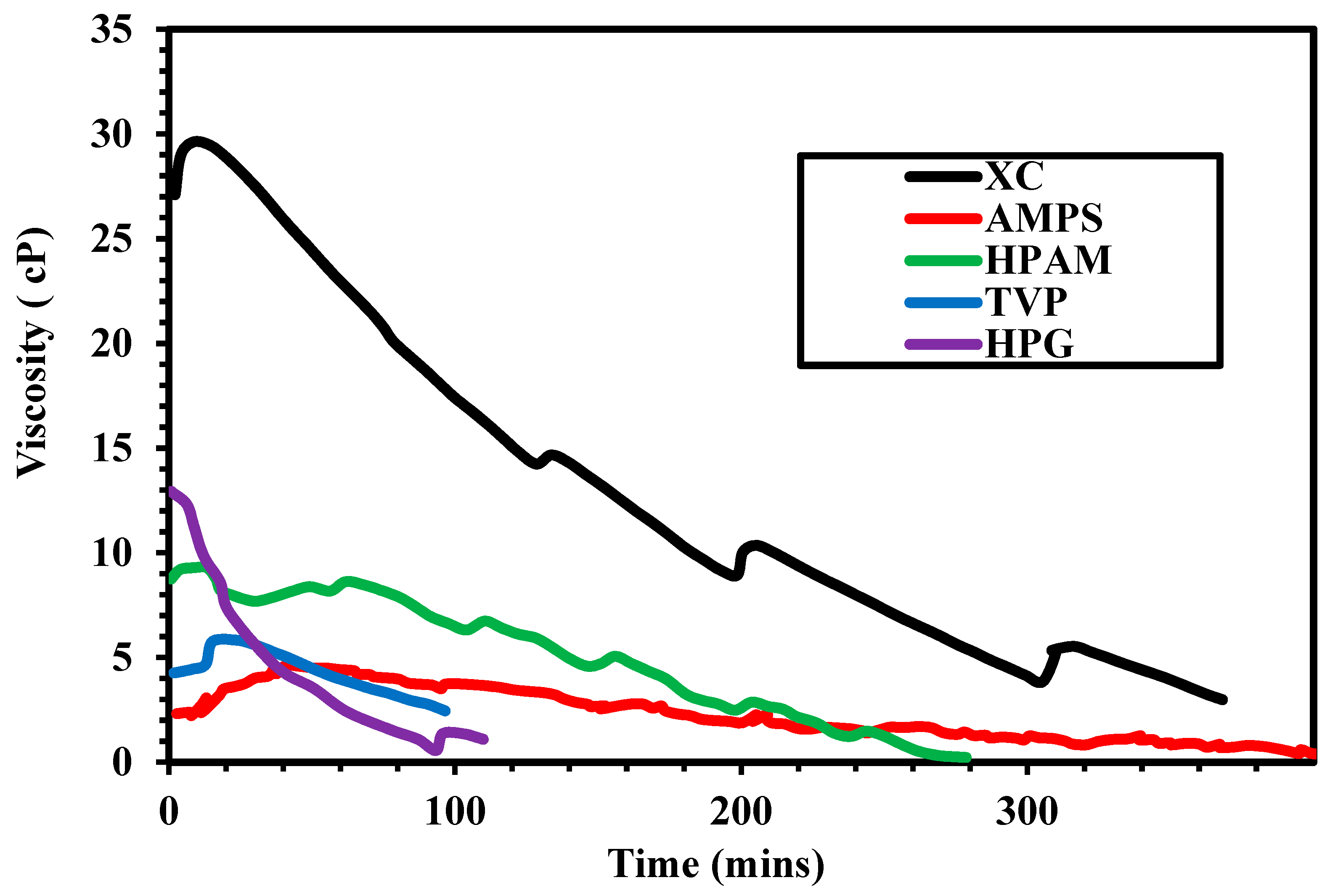
Five different polymers (TVP, HPG, XC, AMPS, and HPAM) at a fixed concentration (20 pptg) were mixed with GLDA (20 wt %) and the apparent viscosity was measured versus time for each sample. Figure 5 shows the viscosity of polymers-GLDA solution in deionized water at 300 °F and 300 psi. The maximum thickening effect was obtained using XC polymer followed by HPAM. The viscosity of the XC polymer was 2.9 cP after 370 min. The HPAM achieved the viscosity of water after 280 min, while the TVP and HPG approached the viscosity of water after 100 min. The minimum thickening effect was achieved using AMPS polymer.
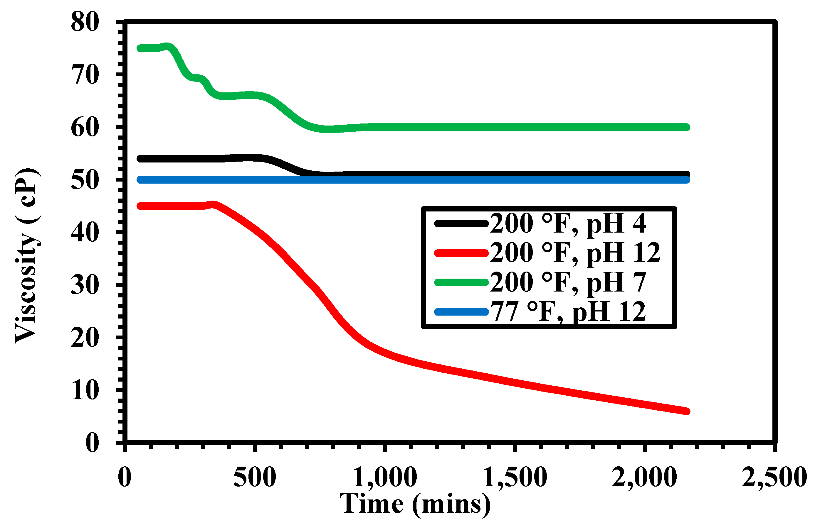
Figure 6 shows the apparent viscosity of GLDA-XC polymer solution at different pH values. The mixing of GLDA with XC increased the apparent viscosity from 33 cP (the apparent viscosity of 0.43 wt % XC alone) to higher values at all investigated pH. At a pH of 4, the apparent viscosity of the GLDA-XC polymer solution increased to 55 cP, which was reduced to 50 cP after 10 h due to breakage of linked branches of the polymer. At a pH of 7, the apparent viscosity increased to 75 cP and reduced to 60 cP after 3.5 h. At a pH of 12, the apparent viscosity of the mixture increased to 45 cP. After 7 h, the viscosity of the mixture was reduced to below the initial value of XC polymer. Only at this pH, both thickening and breaking took place, which is the main requirement in fracturing fluids. This indicates breaking characteristics of GLDA at pH 12. The apparent viscosity of the GLDA-XC polymer solution at room temperature (pH = 12) increased 50 cP and remained intact throughout the entire time of mixing (approx. 40 h), which indicated the failure of breaking at room temperature.
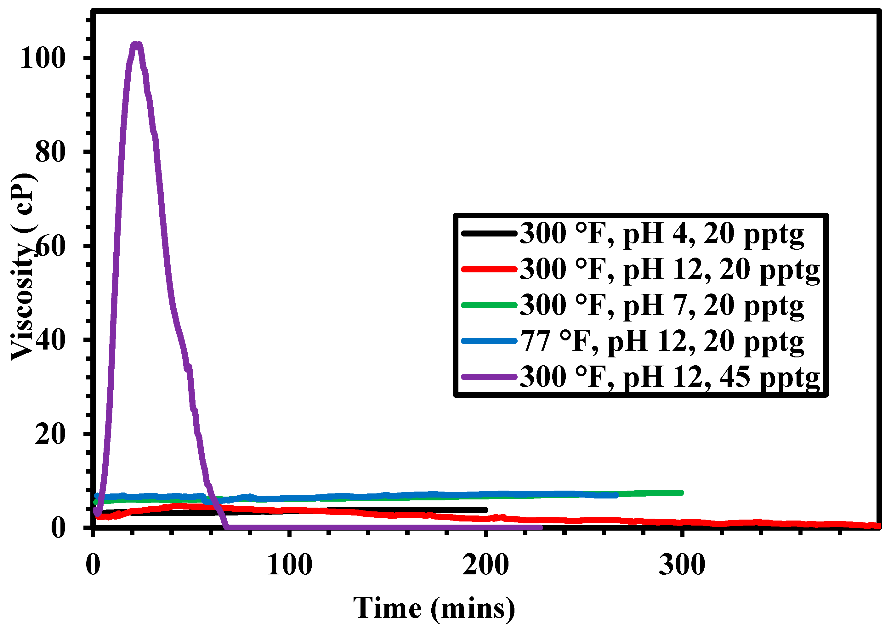
Figure 7 shows the apparent viscosity of the AMPS polymer-GLDA solutions at different pH and temperatures. The viscosity of the AMPS-GLDA solutions is higher when compared to the viscosity of the AMPS solutions. The viscosity at pH 4 and pH 7 was almost constant throughout the experiment and no breakage of the solution viscosity was observed at both pH. However, at pH 12, the viscosity of the AMPS-GLDA solutions was increased initially and then decreased. At low temperature (77 °F), the viscosity of the AMPS-GLDA solution was fluctuating between 6 cP and 7 cP without any breaking. This indicates that, at room temperature, the GLDA thickens the polymer solution but it did not break it. This suggests that viscosity of chelating agent-polymer solution strongly depends on temperature and pH. When the polymer concentration was increased to 45 pptg, the initial viscosity was much higher when compared to the solution with 20 pptg solutions. However, the viscosity declined sharply after 30 min, which indicates the breaking of the polymer chains. As expected, increasing polymer concentration enhanced the viscosity of the thickened fluid. However, the stability of the fluid with time under constant shearing decreased.
The concentration of the GLDA was optimized using 45 pptg of AMPS polymer at 300 °F and pH of 12. The apparent viscosity of GLDA-polymer solutions at a different concentration of GLDA is shown in Figure 8. As observed from Figure, 5 wt % of GLDA yielded a very stable solution under high-temperature high-pressure conditions but the viscosity increase was minimal due to the small concentration of GLDA. The solution’s viscosity is very close to the viscosity of the polymer alone, which indicates that the thickening effect was also minimal on this solution. The similar effect was observed at 10% of GLDA. At higher concentrations (20–40%), the thickening effect was increased significantly. At 40% GLDA, the thickening effect was less compared to the effect at 20% and 30%. The highest viscosity was obtained using a GLDA concentration between 20% to 30% and using 45 pptg of AMPS polymer in fresh water. The results clearly indicate that the viscosity thickening effect can be controlled with the concentration of GLDA, and for optimum conditions, it should not be more than 30 wt %. All of the stimulation operations in the field are performed with a concentration of 20 wt % because it was found to be the optimum in case of stimulation [37,38,39]. In this case, 20% of GLDA also showed the optimum results.

3.3. FTIR Analysis

FTIR analysis was carried out to understand the thickening and breaking mechanism using GLDA. The FTIR analysis of GLDA was conducted at pH 4 and pH 12 (Figure 9). At pH 4, the carboxyl group was identified at the wavenumber 3477 cm−1, which are the functional group of GLDA. It is characterized by a broad spectrum at 3477 cm−1 due to the OH group. The presence of C=O from the carboxyl group was identified at wavenumber 1641 cm−1. At the wave number 1396 cm−1, a peak was found and it was caused by the (C-N) group, however, this group is a non-functional group and it will not contribute to the thickening and breaking of the polymer. At pH 12, two peaks were identified at wavenumbers 1587 cm−1 and 1685 cm−1; the first was associated with C=O of the carboxylate group (COO), while the later was associated with the C=O of a carboxyl group (C(=O) OH). The OH group was also identified at wavenumber 3610 cm−1. Comparison between the two spectra at pH 4 and 12 shows that increasing the pH of GLDA resulted in a reaction between GLDA and base. The reaction between GLDA and base resulted in the partial loss of a proton from COOH group leaving behind the both COOH and COO, which is evident by the two peaks (1587 cm−1 & 1685 cm−1).
FTIR analysis of the polymer in fresh water and polymer/GLDA solution is given in Figure 10. From the spectrum, the amide group (O=C-NH2) was identified as the functional group, with the carbonyl group (C=O) at a wavenumber of 1631 cm−1 and (N-H) at wavenumber 3488 cm−1. A mixture of GLDA (at pH 12) and the polymer in fresh water was prepared, and FTIR analysis was conducted on this fluid at the thickened and breaking stage in order to identify the functional groups responsible for the thickening-breaking effect. The (OH) from GLDA appeared at a wavenumber of 3621 cm−1. The N-H from the AMPS also contributes to this broad peak. The peak around 1670 cm−1 is due to the contribution of carbonyl from amide group of the polymer and COOH from GLDA. The spectrum also shows two distinct (C-N) groups peaks forming at wavenumber 1403 cm−1 and 1322 cm−1, one coming from the GLDA and the other from the polymer. The initial increase in the viscosity is associated with the partial loss of proton at high pH leaving behind the COO. This results in the formation of a complex of GLDA and the polymer that cause an increase in the viscosity. However, there is another competing reaction between the polymer and OH, which will result in the degradation of the polymer chain and viscosity reduction.

3.4. Coreflooding

Two sandstone core samples were cut and prepared for flooding using the continuous pumping setup. The porosity of the core samples was determined by measuring the dry and saturated weight of the core samples. The core samples were dried and weighted, followed by the saturation with 3 wt % KCl. After saturating the core with 3 wt % KCl, the core sample permeability has been measured using the set-up after the flow and pressure difference has been stabilized. The two cores selected were of different permeabilities and different fracturing fluids were evaluated. For high permeability core, 20% GLDA (at pH = 12) with 70 pptg XC polymer was used. For low permeability core, 20% GLDA (pH = 12) with 45 pptg AMPS polymer was injected.

3.4.1. High Permeability Coreflooding

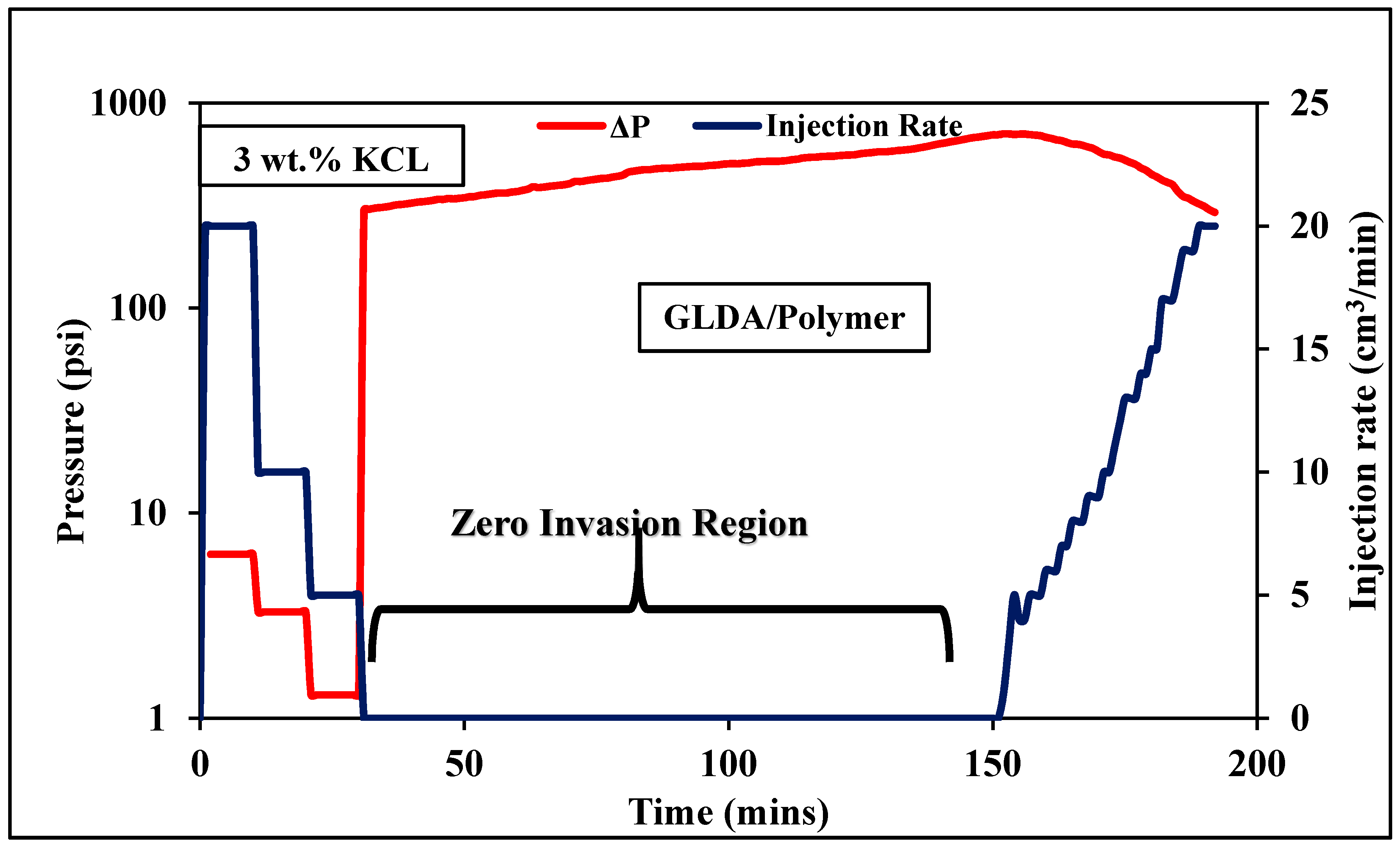
The permeability was calculated using Darcy’s law and the average permeability was found to be 151.2 mD. The fracturing fluid that was used in this core experiment consists of 20 wt % of GLDA (at pH 12) mixed with 70 pptg of XC polymer in fresh water. The reason behind using high polymer concentration is the high permeability of the core sample, which requires a thick fluid system. The viscosity of the developed fluid after thickening reached 200 cP. The experiment was conducted for approximately three hours and the pressure profile is shown in Figure 11. It can be seen from the pressure profile that the fracturing fluid did not flow at the beginning of the experiment due to the high viscosity of the fluid, which suggests that the thickening succeeded. The pressure difference that is required for this fluid to flow was 1048 psi using Darcy’s law. Since the fluid was unable to flow through the core sample, the pressure started to build up until the fluid started to gradually break and hence allowing the fracturing fluid to flow through the core. The pressure started dropping after approximately two hours from the start of the flooding. The return permeability of the core sample was measured by reversing the core and flowing it back with 3 wt % KCl. The average return permeability was found to be 128 mD, and the regained permeability was found to be 85.2% of the original permeability.

3.4.2. Low Permeability Coreflooding

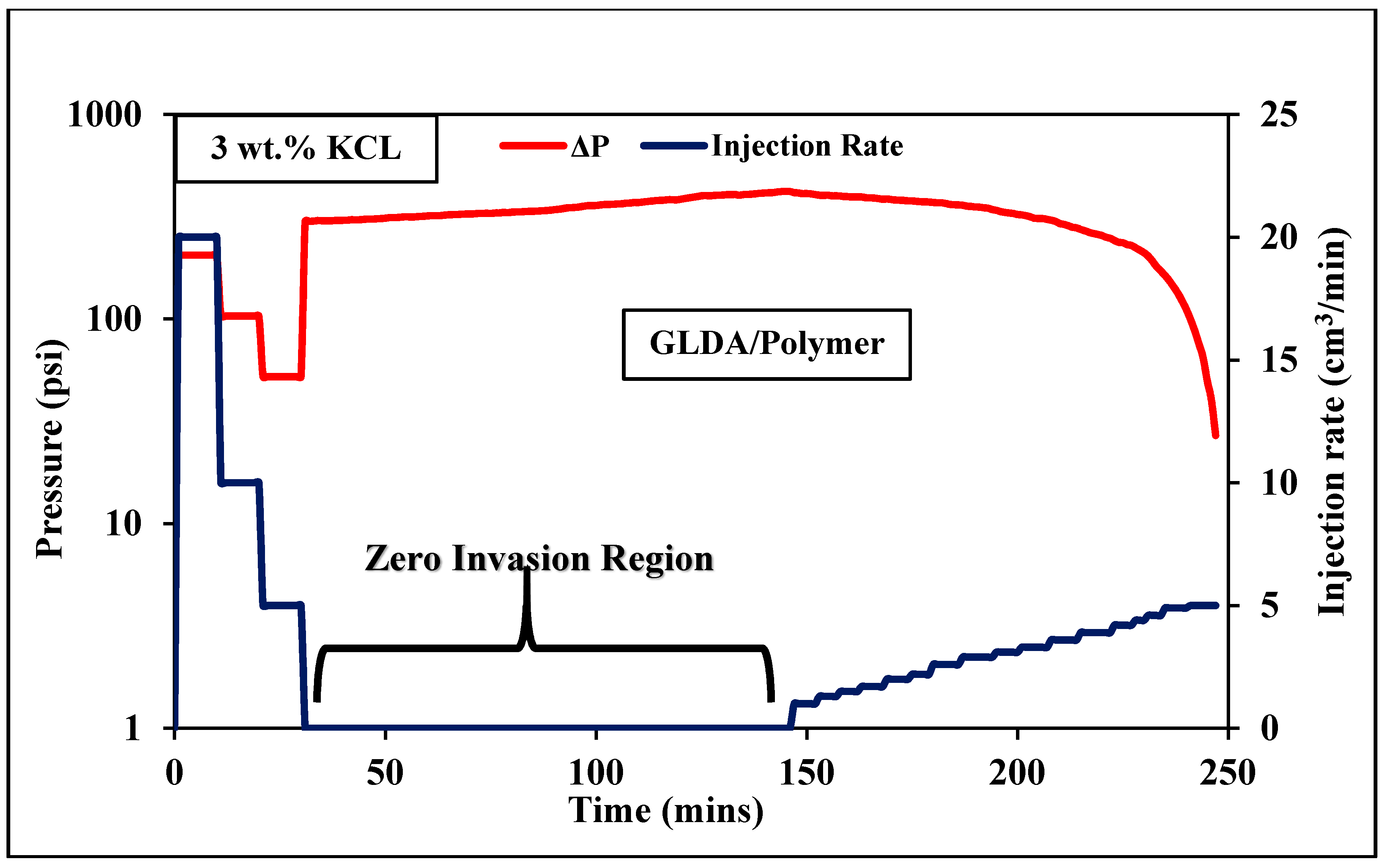
After saturating the core with 3 wt % KCl, the core sample permeability was measured and the average permeability of the core was found to be 3.837 mD. The fracturing fluid was prepared using 20 wt % of GLDA and 45 pptg of AMPS in fresh water. The experiment was conducted for approximately 4 h. It can be seen from the pressure profile (Figure 12) that the fracturing fluid did not flow at the beginning of the experiment due to the high viscosity of the fluid which suggests that the thickening succeeded. The pressure difference that is required for this fluid to flow was 1025 psi using Darcy’s law. Since the fluid was unable to flow through the core sample, the pressure started to build up until the fluid started to gradually break, and hence allowing the fracturing fluid to flow through the core. The pressure started dropping after two hours from the start of the flooding. This result is not with great conformance with the rheology. This is because of the imposed shear rate in a rheological experiment that reduced the stability of the fluid. Whereas, in this case, the fluid was in the static state, which prolonged the breakage of the fluid. The return permeability of the core sample was then measured by reversing the core and flowing it back with 3 wt % KCl. The average return permeability was found to be 3.4067 mD, and the regained permeability was found to be 88.8% of the original permeability.

4. Conclusions

In this work, five different water-soluble polymers and three different chelating agents at various temperature, concentration, and pH were evaluated to develop a new, simple, smart, environmentally-friendly fracturing fluid for fracturing sandstone formations. The fracturing fluid mainly consists of a water-soluble polymer and chelating agent. Thermal stability, rheology, FTIR, and core flooding was performed to determine the optimum conditions and concentration of fracturing fluid. The thermogravimetric analysis reveals that all of the investigated polymers were thermally stable at reservoir temperature. The rheological properties were investigated by changing temperature, pH, shear rate, chelating agent type and concentration, and polymer type and concentration. Among investigated chelating agents, only GLDA shows both thickening and breaking profiles only at basic pH range. EDTA and DTPA showed the thickening behavior but could not break the viscosity. The optimum concentration of the GLDA was found to be between 20% and 30%, and the developed fluid will be more stable at high temperature. Fourier Transform Infrared Spectroscopy analysis was conducted to determine the functional groups that were responsible for the thickening and breaking of the developed fracturing fluid. The main groups that were responsible for the thickening and breaking effect are the amide group (present in the polymer) and the carboxyl group (present in the GLDA). Core flooding experiments were conducted on a low and a high permeability sandstones cores (Scioto & Berea) to prove the effectiveness of the developed fluid, by treating the core surface as the fracture face and studying the invasion of the fluid to the core. The coreflooding of Scioto (low permeability core) yielded a return permeability of 89% and the fluid used composed of 20 wt % of GLDA, 45 pptg of Co-polymer (AMPS) mixed in fresh water. The second coreflooding experiment on Berea sandstone yielded a return permeability of 85% and the fluid that was used to flood composed of 20 wt % GLDA, 70 pptg of XC polymer mixed with fresh water. The developed fluid could result in replacing several additives that are essential in the formulation of typical fracturing fluids, such as cross-linker, breaker, biocide, clay stabilizer, and friction reducer.

Author Contributions

Data curation, M.M. (Marwan Mohammed); Methodology, M.S.K. and S.E.; Project administration, M.M. (Mohamed Mahmoud); Supervision, M.M. (Mohamed Mahmoud); Writing—original draft, M.S.K., and M.M. (Marwan Mohammed); Writing—review & editing, S.E.

Acknowledgments

Mahmoud would like to acknowledge the College of Petroleum Engineering and Geosciences, King Fahd University of Petroleum & Minerals, Saudi Arabia for supporting this work under start-up grant.

Conflicts of Interest

The authors declare no conflict of interest.

References

  1. Li, Q.; Xing, H.; Liu, J.; Liu, X. A review on hydraulic fracturing of unconventional reservoir. Petroleum 2015, 1, 8–15. [Google Scholar] [CrossRef]
  2. Das, A.; Chauhan, G.; Verma, A.; Kalita, P.; Ojha, K. Rheological and breaking studies of a novel single-phase surfactant-polymeric gel system for hydraulic fracturing application. J. Pet. Sci. Eng. 2018, 167, 559–567. [Google Scholar] [CrossRef]
  3. Zhao, J.; Fan, J.; Mao, J.; Yang, X.; Zhang, H.; Zhang, W. High performance clean fracturing fluid using a new tri-cationic surfactant. Polymers 2018, 10, 535. [Google Scholar] [CrossRef]
  4. Fogang, L.T.; Sultan, A.S.; Kamal, M.S. Understanding viscosity reduction of a long-tail sulfobetaine viscoelastic surfactant by organic compounds. RSC Adv. 2018, 8, 4455–4463. [Google Scholar] [CrossRef] [Green Version]
  5. Fogang, L.T.; Sultan, A.S.; Kamal, M.S. Comparing the Effects of Breakers on a Long-tail Sulfobetaine Viscoelastic Surfactant Solution for Well Stimulation. In Proceedings of the Abu Dhabi International Petroleum Exhibition & Conference, Abu Dhabi, United Arab Emirates, 7–10 November 2016. SPE-182915-MS. [Google Scholar]
  6. Ahmed, S.; Elraies, K.A.; Hashmet, M.R.; Alnarabiji, M.S. Empirical modeling of the viscosity of supercritical carbon dioxide foam fracturing fluid under different downhole conditions. Energies 2018, 11, 782. [Google Scholar] [CrossRef]
  7. Fan, M.; Li, J.; Liu, G. New method to analyse the cement sheath integrity during the volume fracturing of shale gas. Energies 2018, 11, 750. [Google Scholar] [CrossRef]
  8. Zhang, C.; Ranjith, P.G. Experimental study of matrix permeability of gas shale: An application to CO2-based shale fracturing. Energies 2018, 11, 702. [Google Scholar] [CrossRef]
  9. Liu, R.; Jian, Y.; Haung, N.; Sugimoto, S. Hydraulic properties of 3d crossed rock fractures by considering anisotropic aperture distributions. Adv. Geo Energy Res. 2018, 2, 113–121. [Google Scholar] [CrossRef]
  10. Parvizi, H.; Rezaei Gomari, S.; Nabhani, F.; Dehghan Monfared, A. Modeling the risk of commercial failure for hydraulic fracturing projects due to reservoir heterogeneity. Energies 2018, 11, 218. [Google Scholar] [CrossRef]
  11. Holditch, S.A. Tight gas sands. J. Pet. Technol. 2006, 58, 86–93. [Google Scholar] [CrossRef]
  12. Assiri, W.; Miskimins, J.L. The Water Blockage Effect on Desiccated Tight Gas Reservoir. In Proceedings of the SPE International Symposium and Exhibition on Formation Damage Control, Lafayette, LA, USA, 26–28 February 2014. SPE-168160-MS. [Google Scholar]
  13. Bennion, D.; Thomas, F.; Schulmeister, B.; Sumani, M. Determination of true effective in situ gas permeability in subnormally water-saturated tight gas reservoirs. J. Can. Pet. Technol. 2004, 43. [Google Scholar] [CrossRef]
  14. Wang, F.; Li, B.; Zhang, Y.; Zhang, S. Coupled thermo-hydro-mechanical-chemical modeling of water leak-off process during hydraulic fracturing in shale gas reservoirs. Energies 2017, 10, 1960. [Google Scholar] [CrossRef]
  15. Civan, F. Analyses of Processes, Mechanisms, and Preventive Measures of Shale-gas Reservoir Fluid, Completion, and Formation Damage. In Proceedings of the SPE International Symposium and Exhibition on Formation Damage Control, Lafayette, LA, USA, 26–28 February 2014. SPE-168164-MS. [Google Scholar]
  16. Middleton, R.S.; Carey, J.W.; Currier, R.P.; Hyman, J.D.; Kang, Q.; Karra, S.; Jiménez-Martínez, J.; Porter, M.L.; Viswanathan, H.S. Shale gas and non-aqueous fracturing fluids: Opportunities and challenges for supercritical CO2. Appl. Energy 2015, 147, 500–509. [Google Scholar] [CrossRef]
  17. Bertoncello, A.; Wallace, J.; Blyton, C.; Honarpour, M.; Kabir, C. Imbibition and Water Blockage in Unconventional Reservoirs: Well management implications during flowback and early production. In Proceedings of the SPE/EAGE European Unconventional Resources Conference and Exhibition, Vienna, Austria, 25–27 February 2014. SPE-167698-MS. [Google Scholar]
  18. Kesavan, S.; Prud’Homme, R.K. Rheology of guar and (hydroxypropyl) guar crosslinked by borate. Macromolecules 1992, 25, 2026–2032. [Google Scholar] [CrossRef]
  19. Jennings, A.R., Jr. Fracturing fluids-then and now. J. Pet. Technol. 1996, 48, 604–610. [Google Scholar] [CrossRef]
  20. Shah, S.; Lord, D.; Rao, B. Borate-crosslinked Fluid Rheology under Various ph, Temperature, and Shear History Conditions. In Proceedings of the SPE Production Operations Symposium, Oklahoma City, Oklahoma, 9–11 March 1997. SPE-37487-MS. [Google Scholar]
  21. Gaillard, N.; Thomas, A.; Favero, C. Novel Associative Acrylamide-based Polymers for Proppant Transport in Hydraulic Fracturing Fluids. In Proceedings of the SPE International Symposium on Oilfield Chemistry, The Woodlands, TX, USA, 8–10 April 2013. SPE-164072-MS. [Google Scholar]
  22. Holtsclaw, J.; Funkhouser, G.P. A crosslinkable synthetic-polymer system for high-temperature hydraulic-fracturing applications. SPE Drill. Complet. 2010, 25, 555–563. [Google Scholar] [CrossRef]
  23. Omeiza, A.; Samsuri, A. Viscoelastic surfactants application in hydraulic fracturing, it’s set back and mitigation—an overview. ARPN J. Eng. Appl. Sci. 2006, 9, 25–29. [Google Scholar]
  24. Samuel, M.; Polson, D.; Graham, D.; Kordziel, W.; Waite, T.; Waters, G.; Vinod, P.; Fu, D.; Downey, R. Viscoelastic Surfactant Fracturing Fluids: Applications in Low Permeability Reservoirs. In Proceedings of the SPE Rocky Mountain Regional/Low-Permeability Reservoirs Symposium and Exhibition, Denver, CO, USA, 12–15 March 2000. SPE-60322-MS. [Google Scholar]
  25. Harris, P. Application of Foam Fluids to Minimize Damage during Fracturing. In Proceedings of the International Meeting on Petroleum Engineering, Beijing, China, 24–27 March 1992. SPE-22394-MS. [Google Scholar]
  26. Ahmed, S.; Elraies, K.A.; Hanamertani, A.S.; Hashmet, M.R. Viscosity models for polymer free CO2 foam fracturing fluid with the effect of surfactant concentration, salinity and shear rate. Energies 2017, 10, 1970. [Google Scholar] [CrossRef]
  27. He, J.; Afolagboye, L.O.; Lin, C.; Wan, X. An experimental investigation of hydraulic fracturing in shale considering anisotropy and using freshwater and supercritical CO2. Energies 2018, 11, 557. [Google Scholar] [CrossRef]
  28. Mahmoud, M.A.; Nasr-El-Din, H.A.; De Wolf, C.A. High-temperature laboratory testing of illitic sandstone outcrop cores with hcl-alternative fluids. SPE Prod. Oper. 2015, 30, 43–51. [Google Scholar] [CrossRef]
  29. Mahmoud, M.A.; Nasr-El-Din, H.A.; De Wolf, C.; Alex, A. Sandstone Acidizing Using a New Class of Chelating Agents. In Proceedings of the SPE International Symposium on Oilfield Chemistry, The Woodlands, TX, USA, 11–13 April 2011. SPE-139815-MS. [Google Scholar]
  30. De Wolf, C.A.; Nasr-El-Din, H.; LePage, J.N.; Mahmoud, M.A.N.-E.-D.; Bemelaar, J.H. Environmentally Friendly Stimulation Fluids, Processes to Create Wormholes in Carbonate Reservoirs, and Processes to Remove Wellbore Damage in Carbonate Reservoirs. U.S. Patent 9150780B2, 6 October 2015. [Google Scholar]
  31. Mahmoud, M.A.N.E.-D.; Gadallah, M.A. Method of Maintaining Oil Reservoir Pressure. U.S. Patent 20140345868A1, 27 November 2014. [Google Scholar]
  32. Kamal, M.S.; Shakil Hussain, S.M.; Fogang, L.T. A zwitterionic surfactant bearing unsaturated tail for enhanced oil recovery in high-temperature high-salinity reservoirs. J. Surfactants Deterg. 2018, 21, 165–174. [Google Scholar] [CrossRef]
  33. Ahmad, H.M.; Kamal, M.S.; Al-Harthi, M.A. High molecular weight copolymers as rheology modifier and fluid loss additive for water-based drilling fluids. J. Mol. Liq. 2018, 252, 133–143. [Google Scholar] [CrossRef]
  34. Shahzad Kamal, M.; Sultan, A. Thermosensitive Water Soluble Polymers: A solution to High Temperature and High Salinity Reservoirs. In Proceedings of the SPE Kingdom of Saudi Arabia Annual Technical Symposium and Exhibition, Dammam, Saudi Arabia, 24–27 April 2017. SPE-188006-MS. [Google Scholar]
  35. Malik, I.A.; Al-Mubaiyedh, U.A.; Sultan, A.S.; Kamal, M.S.; Hussein, I.A. Rheological and thermal properties of novel surfactant-polymer systems for eor applications. Can. J. Chem. Eng. 2016, 94, 1693–1699. [Google Scholar] [CrossRef]
  36. Ahmad, H.M.; Kamal, M.S.; Al-Harthi, M.A. Rheological and filtration properties of clay-polymer systems: Impact of polymer structure. Appl. Clay Sci. 2018, 160, 226–237. [Google Scholar] [CrossRef]
  37. Mahmoud, M.; Abdelgawad, K.Z.; Elkatatny, S.M.; Akram, A.; Stanitzek, T. Stimulation of seawater injectors by glda (glutamic-di acetic acid). SPE Drill. Complet. 2016, 31, 178–187. [Google Scholar] [CrossRef]
  38. Ameur, Z.O.; Kudrashou, V.; Nasr-El-Din, H.; Forsyth, J.; Mahoney, J.; Daigle, B. Stimulation of High Temperature Sagd Producer Wells Using a Novel Chelating Agent (glda) and Subsequent Geochemical Modeling Using Phreeqc. In Proceedings of the SPE International Symposium on Oilfield Chemistry, The Woodlands, TX, USA, 13–15 April 2015. SPE-173774-MS. [Google Scholar]
  39. Braun, W.; De Wolf, C.A.; Nasr-El-Din, H.A. Improved Health, Safety and Environmental Profile of a New Field Proven Stimulation Fluid. In Proceedings of the SPE Russian Oil and Gas Exploration and Production Technical Conference and Exhibition, Moscow, Russia, 16–18 October 2012. SPE-157467-MS. [Google Scholar]
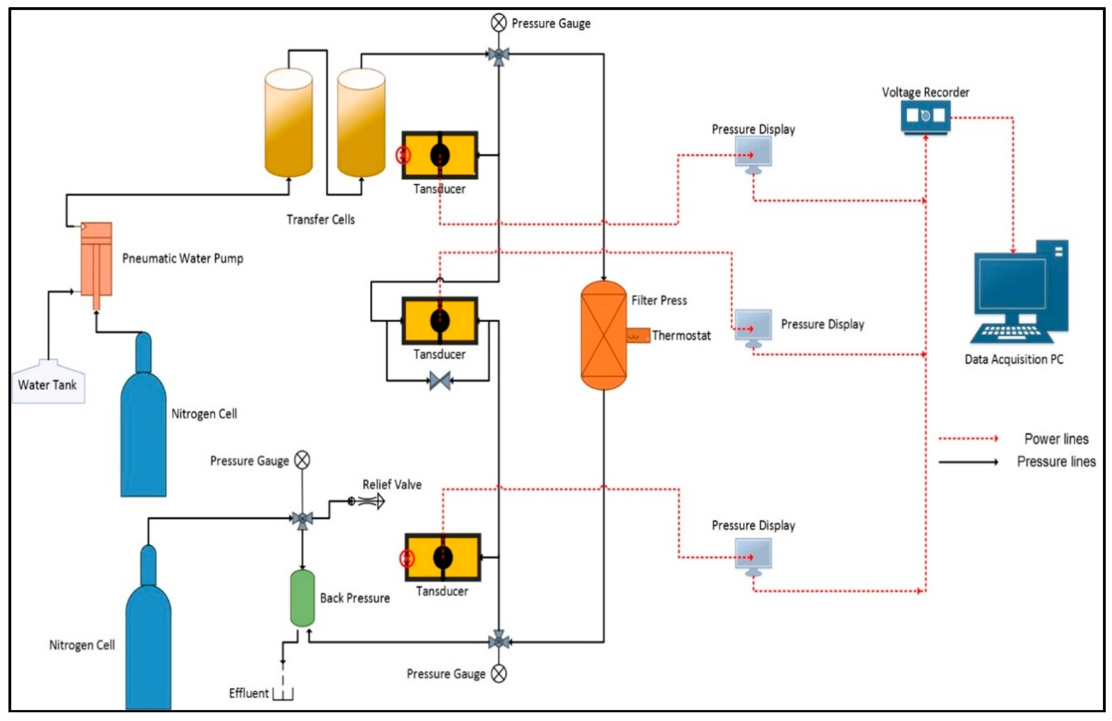
Figure 1. Filter-Press with continuous pumping set-up.
Energies 11 01663 g001
Figure 2. Cell and Core specifications of the continuous pumping set up.
Energies 11 01663 g002
Figure 3. Thermogravimetric analysis of polymers used in this work.
Energies 11 01663 g003
Figure 4. Apparent viscosity of xanthan gum (0.43 wt %) with three different chelating agents (20 wt %) in deionized water (Shear rate- 170.3 s−1, T = 200 °F, P = 300 psi, pH = 12).
Energies 11 01663 g004
Figure 5. Apparent viscosity of different polymers (20 pptg) with glutamic acid diacetic acid (GLDA) (20 wt %) in deionized water (Shear rate = 511 s−1, T = 300 °F, P = 300 psi, pH = 12).
Energies 11 01663 g005
Figure 6. Apparent viscosity XC polymer (0.43 wt %) with GLDA (20 wt %) at different pH values (Shear rate- 170.3 s−1, P = 300 psi).
Energies 11 01663 g006
Figure 7. Apparent viscosity of acrylamide (AMPS) polymer with GLDA (20 wt %) at different conditions (Shear rate = 511 s−1, P = 300 psi).
Energies 11 01663 g007
Figure 8. Apparent viscosity of AMPS polymer with a different concentration of GLDA at 300 °F (Shear rate = 511 s−1, P = 300 psi, pH = 12).
Energies 11 01663 g008
Figure 9. Fourier Transform Infrared Spectroscopy (FTIR) analysis of GLDA at different pH.
Energies 11 01663 g009
Figure 10. FTIR analysis of polymer in deionized water and developed fracturing fluid.
Energies 11 01663 g010
Figure 11. Coreflooding data for the GLDA-XC polymer solution.
Energies 11 01663 g011
Figure 12. Coreflooding data for GLDA-AMPS polymer solution.
Energies 11 01663 g012
Table 1. The structure of the polymers used in this study.
PolymerAbbreviationStructure
Partially hydrolyzed polyacrylamide HPAM Energies 11 01663 i001
Xanthan Gum XC Energies 11 01663 i002
Guar GumHPG Energies 11 01663 i003
Thermoviscofying polymer TVP Energies 11 01663 i004
Copolymer of 2-acrylamido-2-methylpropane sulfonic acid and acrylamideAMPS Energies 11 01663 i005
Table 2. The structure of the chelating agents used in this study.
Chelating Agent Abbreviation Structure
glutamic acid diacetic acid GLDA Energies 11 01663 i006
Ethylenediaminetetraacetic acidEDTA Energies 11 01663 i007
Diethylenetriaminepentaacetic acidDTPA Energies 11 01663 i008
Table 3. Core Sample Characterization.
Sample12
TypeSandstoneSandstone
OriginBereaScioto
Diameter6.35 cm6.35 cm
Length5.08 cm5.08 cm
Pore Volume35.4 cm319.3 cm3
Bulk Volume160.8 cm3160.8 cm3
Porosity22%12%
Pemreability151.2 mD3.837 mD
Table 4. Mineral composition of the core samples.
MineralsBereaScioto
Quartz8670
Dolomite1-
Calcite2-
Feldspar32
Kaolinite5Trace
Illite118
Chlorite24
Plagioclase-5