1. Introduction
Permanent magnet synchronous motors (PMSMs) have the advantages of simple structure, reliable operation, high power density, and have been widely used in many industrial fields, such as aerospace, mechanical manufacturing, rail traffic and other industrial fields [
1,
2,
3]. In recent years, PMSM research has gradually become a hot spot. Reference [
4] adjusts the parameter of a PID controller by using a wavelet algorithm to control a PMSM. References [
5,
6,
7] develop an observer to reduce the number of sensors in the PMSM control system. In order to obtain more accurate parameters in motor control, references [
8,
9] study PMSM parameter identification technologies. Predictive torque control (PTC) is applied to PMSM control systems in order to give comprehensive consideration to the dynamic and steady performance of the motor system, which is simple in principle and easy to implement online, and has received extensive attention in academia and industry [
10,
11].
In the voltage source inverter-permanent magnet synchronous motor (VSI-PMSM) drive system, finite control set predictive torque control (FCS-PTC) takes the discrete nature of inverter switching states into account. FCS-PTC substitutes switching states into the motor predictive model one by one, evaluates prediction results by the cost function, and chooses the switching state minimizes the cost function as the optimal input of the inverter. It is theoretically simple, easy to implement online, and has gained extensive attention in both academia and industry [
12,
13,
14,
15].
The traditional FCS-PTC only uses one set switching state during a control period, making it respond quickly when the torque or flux changes abruptly. However, a two-level three-phase inverter has only eight switching states, limiting the finite control set to only seven voltage vectors (two zero vectors). This results in large ripples in torque and flux at steady state [
16,
17,
18,
19,
20,
21,
22]. In addition, the traditional FCS-PTC needs to substitute all seven voltage vectors into the predictive model one by one in each control period, and then screen out the vector that minimizes the cost function. This step of online optimization needs to be iterated seven times. Worse, in the case of multi-step prediction or multi-level inverter, the number of iterations increases exponentially.
In view of the defects of large torque ripple in the traditional single vector control, many scholars add duty cycle modulation to improve it [
23,
24,
25,
26,
27,
28,
29,
30]. Reference [
24] added duty cycle modulation to the traditional single vector predicative control strategy, so that an effective vector and a zero vector are acted during one control period. The optimal effective vector is determined by the cost function of the traditional predictive torque control, and its action time is determined by torque deadbeat method or torque ripple minimum method [
27]. The remaining time in the control period is taken by zero vector. This predictive torque control with duty cycle modulation, referred to as traditional Duty-PTC in the following text, can reduce torque ripple compared to the single vector predictive torque control.
In fact, according to the motor’s operating conditions, the performance of a combination of two effective vectors outperforms that of a combination of an effective vector and a zero vector. References [
28] proposed a generalized double-vector predictive torque control based on traditional Duty-PTC, where the acted vectors in one control period can be not only a combination of an effective vector and a zero vector, but also two effective vectors. This method reduces torque ripple by optimizing the vector action time, namely, by duty cycle modulation. However, since this method provides 25 vector combinations, it has to calculate 25 duty cycles for each control period. In this way, the optimization step by cost function is conducted 25 times. This leads to a large computation amount, and the switching frequency hasn’t been taken into account in the vector combinations. References [
30,
31] take switching frequency into account on the basis of generalized double-vector predictive torque control, and optimize the selection of the second vector, so as to reduce the torque ripple of the motor without causing a high switching frequency. However, the methods above screen out the first vector first, and then calculate the duty cycle, and then obtain the second action vector. The selection of the two action vectors and the determination of their duty cycles were not carried out simultaneously. In addition, some scholars proposed a method to apply three vectors in one control period to reduce torque ripple [
32,
33,
34], where [
32] used two effective vectors and a zero vector, and optimized the vector action time by duty cycle modulation, thus reducing motor torque and flux ripple, but it needs to calculate two duty cycles within each control period, making its implementation complicated. Worse still, with the increase of the number of vectors in each control period, the switching frequency will increase.
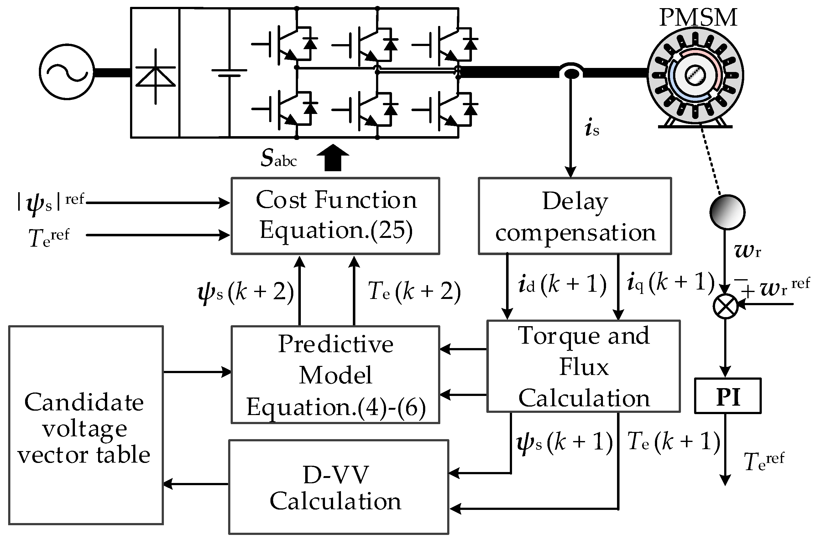
In order to improve the steady-state control accuracy of PMSM and to reduce torque ripple, a dual-vector predictive torque control strategy based on candidate vector table is proposed in this paper. First, this novel strategy takes the inverter switching frequency into account, combines basic voltage vectors, and determines the synthesized vector set comprising double-vector combinations, so as to reduce torque ripple without causing a higher switching frequency. Then, using the position relation between the desired voltage vector and the synthesized vector set, the candidate vector table is constructed offline, and three sets of candidate vectors and their duty cycles are obtained by looking up the table. Finally, through the experimental comparison and analysis of traditional FCS-PTC and Duty-PTC concerning their steady-state and dynamic performance, the proposed strategy is proved feasible and effective.
2. Dual-Vector Predictive Model of PMSM
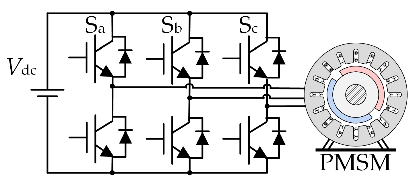
The two-level voltage source inverter-fed PMSM system is shown in
Figure 1. Switch variables are defined as
Si,
i ∈ {a, b, c}, representing the switch state of the inverter bridge arm switch tube:
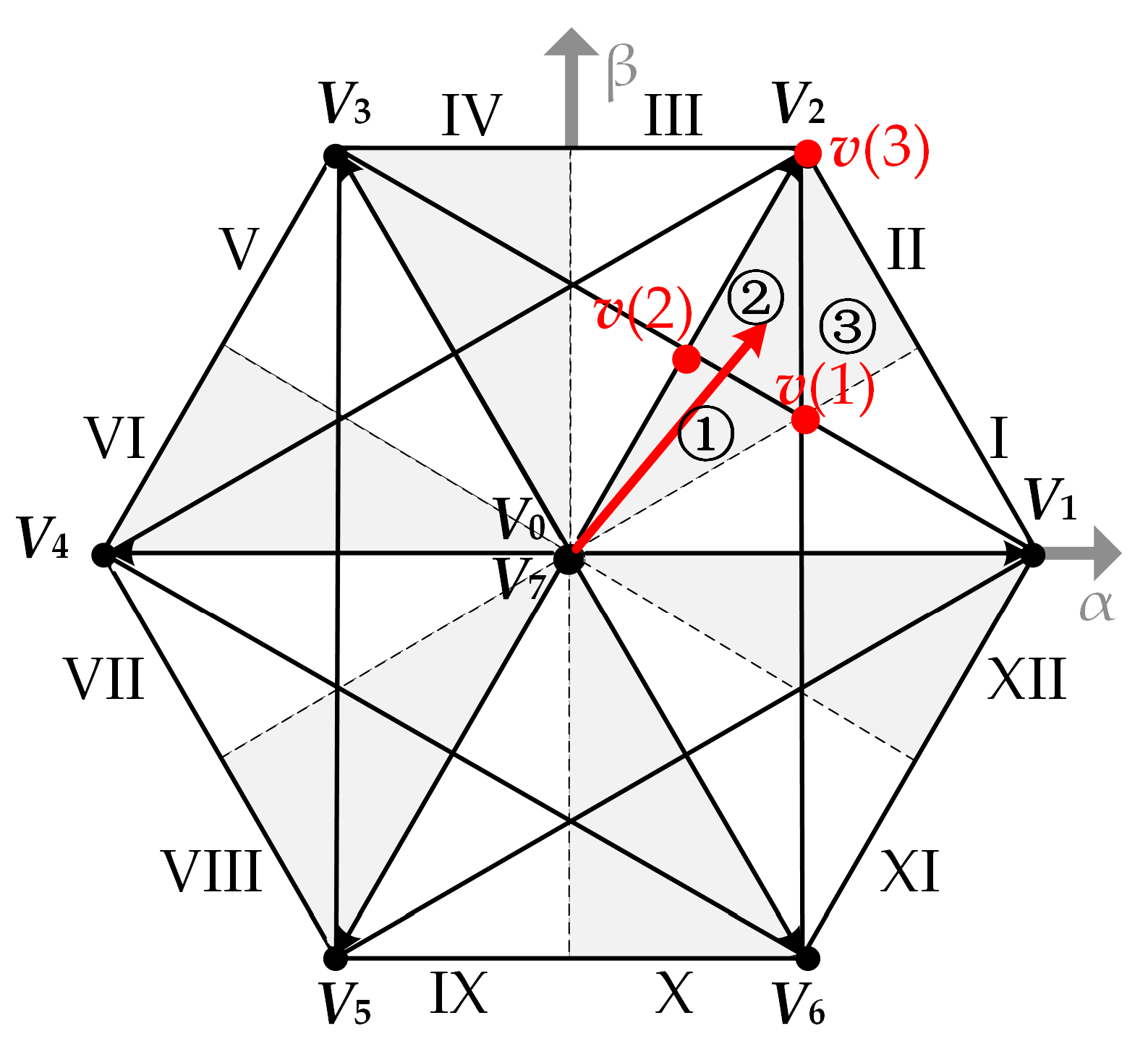
According to the above definition, there are eight optional switch states in total, corresponding to 8 voltage vectors Vm (m ∈ {0, 1, 2, 3, 4, 5, 6, 7}). Among them, V1–V6 are effective vectors, V0 and V7 are zero vectors.
The voltage equations of the PMSM in dq frame are expressed as:
where
usd,
usq,
isd,
isq,
ψsd, and
ψsq are d-axis and q-axis component of stator voltage, stator current and stator flux, respectively; ω
r is the rotor electrical angular speed;
Rs is the stator resistance.
The flux and torque equations are as:
where
ψf is the rotor flux;
Ld,
Lq are d-axis and q-axis inductance respectively;
Te is the electromagnetic torque;
p is pole pairs of motor.
According to the Equations (1) and (2), the stator current is selected as a state variable, and the state-space equation of motor can be obtained. Discretizing the state-space equation, then the stator current predictive model is obtained as:
where
Ts is the control period of the system;
isd (
k),
isq (
k),
isd (
k + 1) and
isq (
k + 1) are d-axis and q-axis components of stator current at
kTs and (
k + 1)
Ts, respectively;
u1sd (
k),
u1sq (
k),
u2sd (
k),
u2sq (
k) are d-axis and q-axis stator voltage of the two voltage vectors at
kTs respectively;
t1 ∈ [0,
Ts] is the action time of the first voltage vector.
Combining (2) and (3), the stator flux predictive model and the torque predictive model are obtained as:
where
ψsd(
k + 1),
ψsq(
k + 1) are d-axis and q-axis stator flux at (
k + 1)
Ts respectively;
ψs (
k + 1),
is (
k + 1),
Te(
k + 1) are stator flux, stator current, and electromagnetic torque at (
k + 1)
Ts respectively.
5. Conclusions
In this paper, the two-level inverter-fed PMSM drive system is taken as the research object. By analyzing the characteristics of the synthesized vector set, a dual vector predictive torque control strategy based on the candidate vector table is proposed.
The action vector combination in one control period can be either an effective-zero combination or an effective-effective combination, so that the torque ripple can be effectively reduced. At the same time, the vector combination takes the switching frequency into account, so it can effectively reduce the torque ripple without causing high switching frequency. In this paper, a candidate vector table is constructed offline, and three sets of candidate vectors and their duty cycles can be determined by looking up the table, so the two vectors acted in a control period and their duty cycles can be obtained simultaneously.
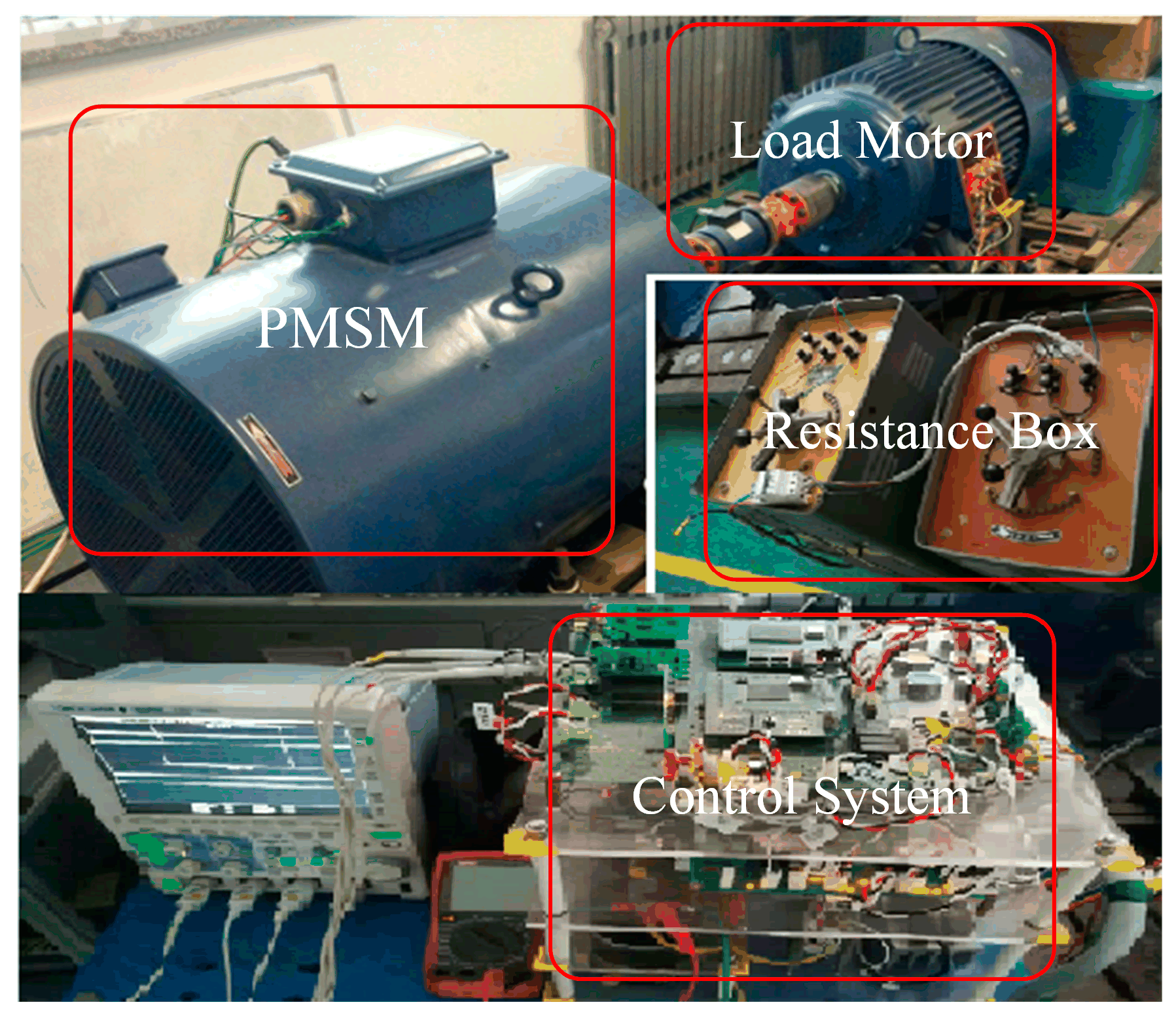
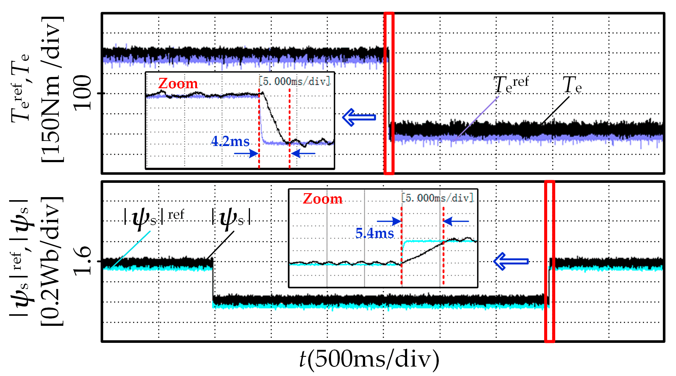
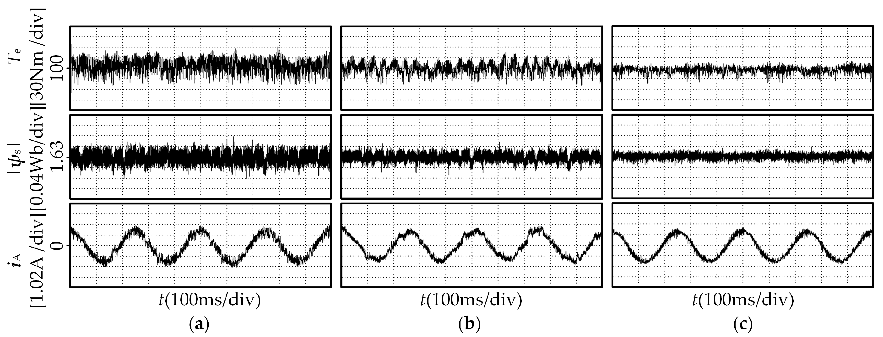
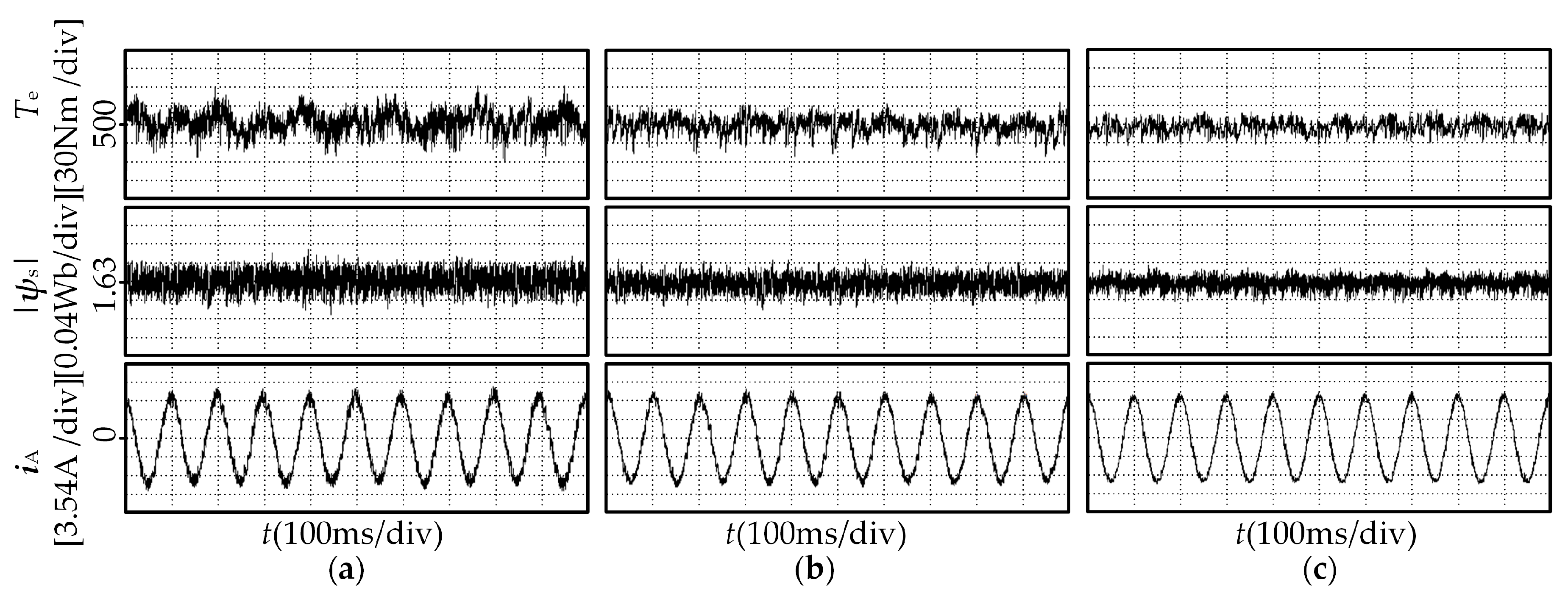
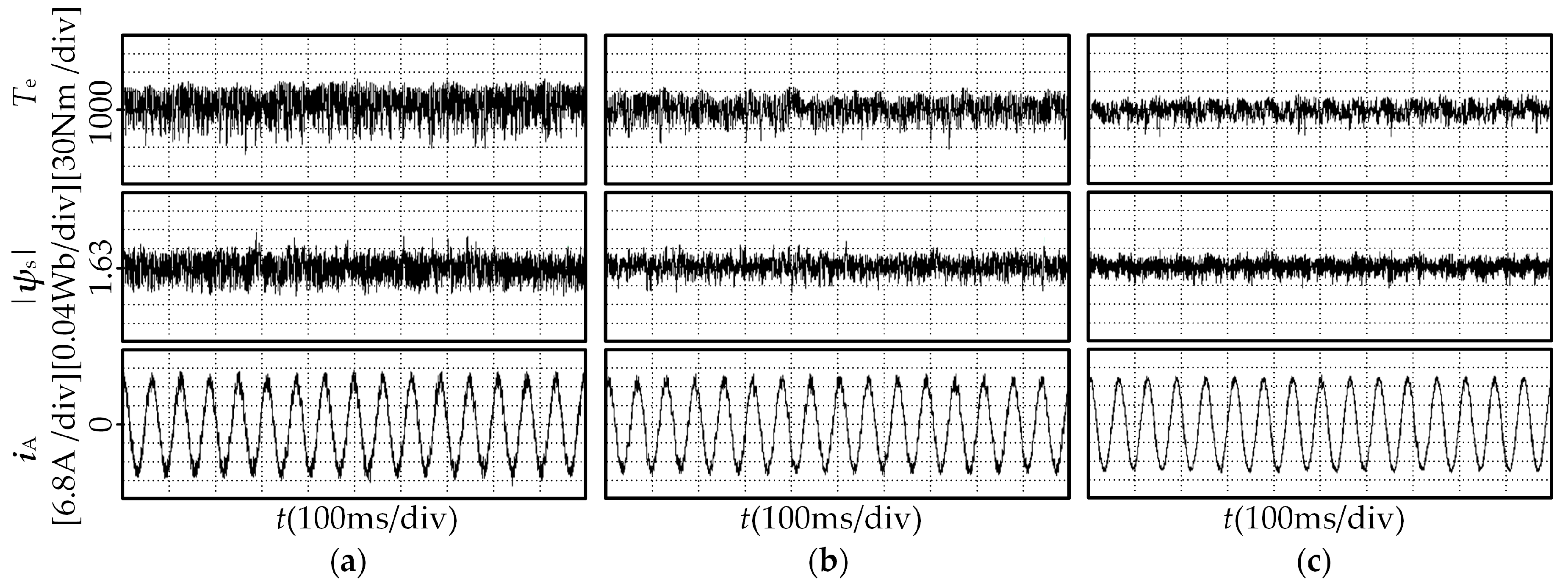
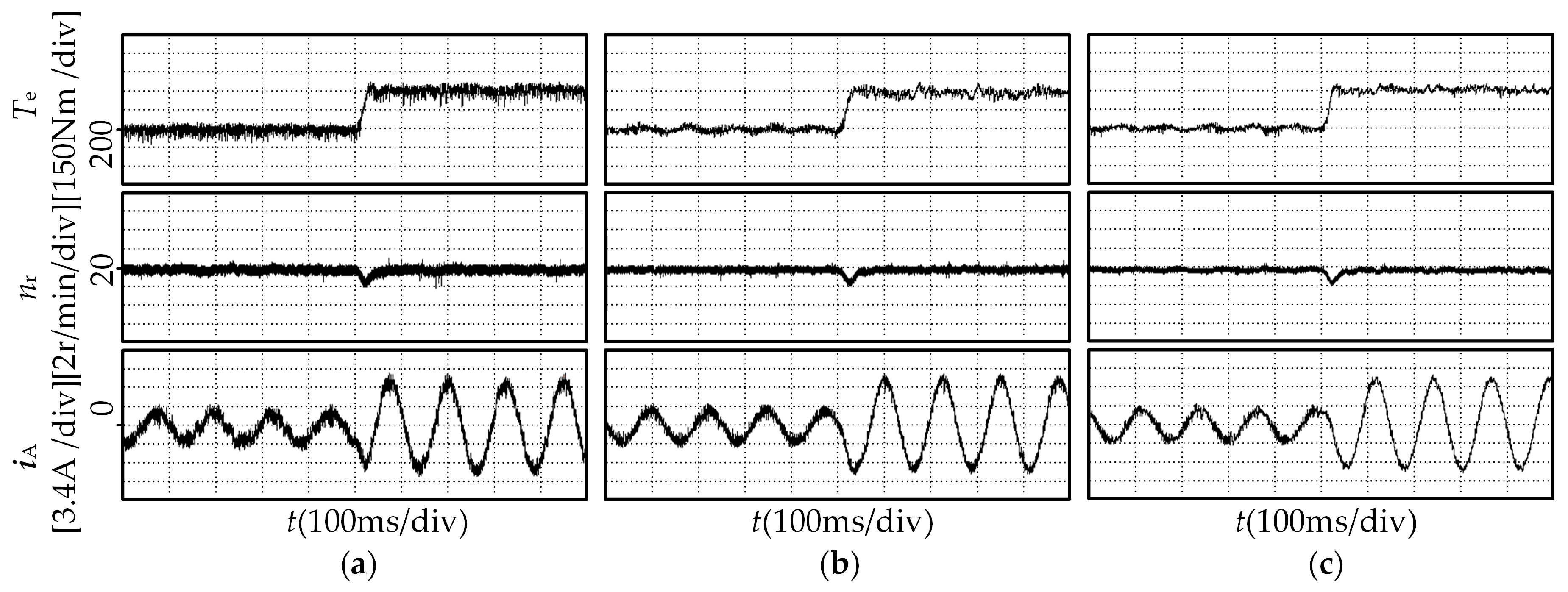
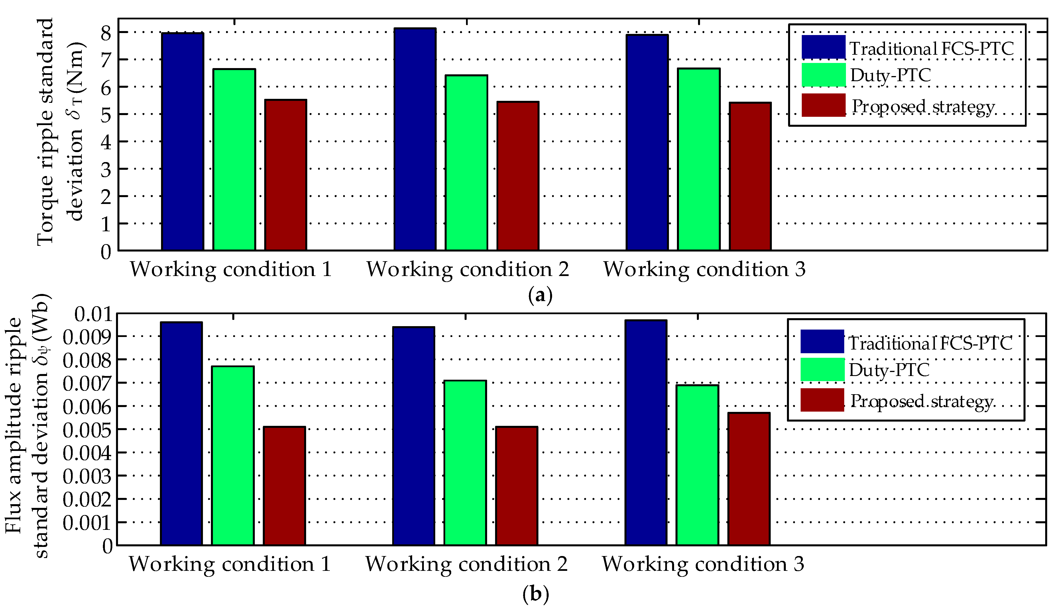
Finally, the feasibility and effectiveness of the proposed method are verified on a 5.2 kW two-level inverter-fed PMSM drive system. The experimental results show that, compared with the traditional FCS-PTC and Duty-PTC, the torque and flux amplitude ripples of the proposed strategy are significantly reduced under all of the three working conditions. The dynamic response time of the three control strategies are almost the same.
Although the proposed control strategy is aimed at the two-level inverter-fed PMSM drive system, the future research work can focus on extending the proposed method to other kinds of inverter-fed motor systems to improve the generality of the proposed control strategy. Given the dependence of the PMSM model predictive torque control on the motor parameters, it is necessary to study the robustness of the control system in further researches.


