Article

Study on a New Gasoline Particulate Filter Structure Based on the Nested Cylinder and Diversion Channel Plug

1
School of Transportation Science and Engineering, Beihang University, Beijing 100083, China
2
Propulsion System Department, Pan Asia Technical Automotive Center Co., Ltd., Shanghai 201201, China
3
College of Mathematics & Statistics, Hebei University of Economics and Business, Shijiazhuang 050061, China
*
Authors to whom correspondence should be addressed.
Energies 2019, 12(11), 2045; https://doi.org/10.3390/en12112045
Submission received: 5 April 2019 / Revised: 24 May 2019 / Accepted: 26 May 2019 / Published: 28 May 2019
(This article belongs to the Section D: Energy Storage and Application)

Abstract

:
Increasingly stringent emission regulations have imposed strict requirements on the particulate matter (PM) from gasoline direct injection (GDI) engines, and the gasoline particulate filters (GPFs) are considered one of the most promising devices for meeting these requirement. To reduce the flow resistance of the GPF, a type of nested cylinder and diversion channel plug (NC-DCP) GPF is designed. It is composed of nested foam metal cylinders and annular diversion channel plugs. The pressure drop and its influencing factors were theoretically studied. The results show that the structural parameters, such as the cylindrical layer spacing and the length-to-diameter ratio, and the pressure drop have trade-off relationships. Moreover, the filtration efficiency is analyzed, and the calculation formula is summarized. The internal flow field distribution and its influencing factors are discussed based on a 2-D axisymmetric simulation. The results show that the exhaust velocity affects the flow field uniformity but does not affect the flow field structure. The pressure drop gradually decreases as the number of nested layers increases, and the positive direction is beneficial to reduce the overall pressure drop. Under different velocities, there is an optimal length-to-diameter ratio to minimize the pressure drop, and the simicircular diversion plug greatly improves the flow uniformity index for the internal flow field of the filter element.

1. Introduction

Gasoline engines as traditional power units have been widely used in cars and trucks. During the application and development of the gasoline engine, gasoline direct injection (GDI) was highly regarded for its excellent dynamics, characteristics, and economy [1]. In GDI engines, fuel is injected directly into the combustion chamber. This can achieve better combustion and operation at higher compression ratios, thereby reducing the fuel consumption and increasing the power [2,3,4,5]. Compared with port fuel injection (PFI) engines, the fuel efficiency under certification test cycle can be increased by 10–15% using small and turbocharged GDI engines [6,7].
However, compared to traditional PFI engines, GDI engines have some drawbacks. The direct injection of gasoline into the cylinder causes a short mixing time of fuel and gas before ignition. In addition, injecting the fuel directly into the cylinder can cause wall wetting [8,9]. These can lead to incomplete combustion and consequent particulate formation [10], which can cause a large amount of particulate matter (PM) in the exhaust. These are fine particles, broadly in the range from 10–100 nm [11]. Actually, for GDI engines, the emissions may be low on a mass basis (mg/km) but can be very high on a number basis, 1011–1013 #/km (number of solid particles emitted per kilometer), much more than PFI engines, exceeding the particulate number (PN) limit of 6 × 10¹¹ #/km in China and Europe. Compared with diesel engines equipped with diesel particulate filters (DPFs), modern gasoline engines can emit more PM [12,13].
Gasoline particulate filters (GPF) are effective devices for reducing PM emissions. With increasingly stringent emission regulations, research regarding the application of PM filters in GDI engines will become an inevitable trend. The particulate filter must have high filtration efficiency and a long life and satisfy other requirements, and the flow resistance (pressure drop) must be small. The physical characteristics of DPFs have been fully understood and documented [14,15], and these insights can be applied to GPFs. Initially, soot is captured in the wall, known as “deep-bed” filtration. When the filter is fresh, the filtration efficiency (the proportion of particles trapped) is not 100%, but it increases with the mileage. Soot and ash accumulation forms a layer on the filter wall to prevent further penetration of soot into the wall, which is helpful to improve the filtration efficiency. The regeneration of soot can lead to breakage of the soot cake layer, which will reduce the filtration efficiency. However, in most driving conditions and life periods of a vehicle, the filtration efficiency of the GPF is expected to be very high (>90%) [16].
The filter element is the key component to determining the performance of the GPF, so the material selection and structure design of the filter element are very important.
Cordierite is commonly used in traditional filter element materials. It has a low thermal expansion coefficient and good thermal shock performance, which makes it a mature material for both flow-through substrates and wall-flow filters [17,18]. Silicon carbon (SiC) or aluminum titanate (AT) have properties of high heat capacities and densities, thus are widely used in heavy soot load applications of diesel. Meanwhile, foam metal is also widely used in the field of exhaust purifiers [19,20,21]. Compared to traditional materials, foam metal not only has a good filtration performance, such as a high porosity, high permeability, high specific surface area, and temperature resistance, but also has better impact resistance and easier processing, compensating for the shortcomings of traditional filtration materials. Foam metal was first developed by Sosnick in the United States [22]. The method was to add mercury metal into liquid aluminum and then solidify the foam aluminum. In the following years, researchers have performed many studies regarding the production methods, structural optimization, performance improvement, and application of foam metal [23]. The commonly used foam metals include foam nickel. Foam nickel is a foam metal material widely used in the fields of electrochemistry, functional materials, thermal engineering, etc. It is used as a battery electrode material and catalyst carrier, especially for filtering materials that require high temperature resistance (nickel foam material can withstand a high temperature of 1100 °C) and acid and alkaline corrosion resistance, as are surface materials in infrared burners, and as a heating materials in industrial drying equipment.
Another key requirement of GPFs is a low pressure drop through the filter, which increases the flow resistance that the exhaust should overcome.
A lot of studies about the pressure drop in the DPFs has been finished with the filtration mechanisms [24,25,26,27,28], and most of the studies can be applied on GPFs.
The pressure drop (clean GPF) can be divided into four parts: contraction and expansion, pressure drop as the gas enter and leaves the filter, pressure drop caused by friction when the gas passing through the channels, and the gas flowing across the filter wall.
To reduce the pressure drop, the methods from multiple perspectives have been investigated, like optimizing the channel structure and developing new materials, and the particle deposition and transportation inside the filtration wall [21,25,26,29]. Some of the methods address the importance of improving the flow uniformity inside the filter element, but the topic of managing the flow before it enters the filter element has not received adequate attention in previous research.
In a conventional DPF, the flow uniformity should be considered seriously, Ma et al. found that more than 88% exhaust flow passing through 53% of the filter cross-sectional area [30]. To get a uniform flow distribution, Howitt et al. placed a flow-tailoring devices before the filter element, however, the devices increased not only the pressure drop but also the thermal mass of the system, the increased thermal mass will delay the catalyst light-off [31]. Bella et al. introduced the diverging section of the inlet to improve the flow uniformity under similar flow constraints, which shows good results when the flow is crossing the channels [32]. For the wall-flow filter, the diversion channel plug is the device that can influence the flow uniformity inside the filter element, but not many relevant studies have been found.
The new type of GPF consisting of a nested foam metal cylinder and annular diversion plug is designed by the authors [33]. This filter is hereafter referred to as a nested cylinder and diversion channel plug (NC-DCP) GPF, which aims to reduce the flow resistance and the size and quality of the filter, as well as to improve its surface area and compactness. To analyze the flow field distribution and reduce the pressure drop in the NC-DCP GPF, a two-dimensional steady flow model of the NC-DCP GPF was established using the commercial computational fluid dynamics (CFD) software Fluent 15.0. The effects of the number of nested layers of the filter element, the direction of air flow and the diversion plug on the pressure drop and the flow distribution in the NC-DCP GPF were studied.

2. Structural Design of the NC-DCP GPF

2.1. Design of the Filter Element and Overall Structure

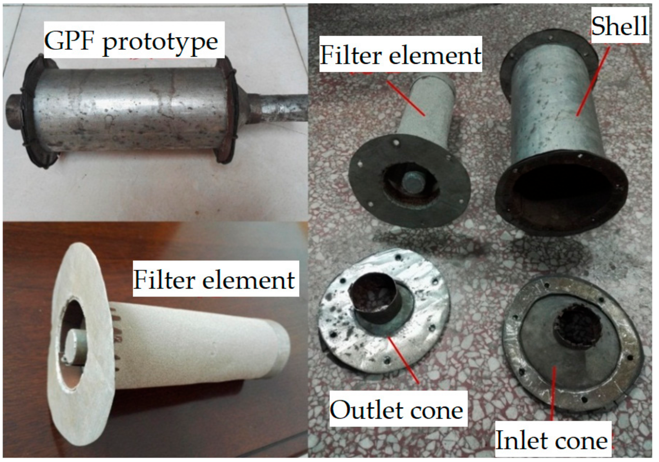
As foam metal has good processability and high strength, this paper selects foam metal as the NC-DCP GPF element material. Figure 1 is an example of the filter element designed by the authors. The filter element is comprised of four foam metal cylinders. The two ends of the cylinders (channels) are precisely positioned, and the cylinders are spaced apart from each other. The sealing area is guided by the semicircular flow diversion plug to ensure the movement of the air flow, such that only one side of each annular space is blocked.
This structure ensures that the exhaust gas does not directly reach the other side of the filter element through the annular channel but must instead flow through the foam metal microporous channel wall surface. When gas flows through the micropore, particles larger than the diameter of the micropore are filtered by sieving, while particles smaller than the diameter of the micropore remain in the micropores of the filter porous medium by adsorption.
Using the filter element shown in Figure 1, the NC-DCP GPF is designed, as shown in Figure 2. The arrow in the figure shows the flow direction of the exhaust gas. Cross sections 4–5 shows the filter element, cross sections 2–3 illustrates the expansion cone (inlet cone), and cross sections 6–7 shows the contraction cone (outlet cone). The exhaust gas passes through the sections in cross section 1 and finally enters the exhaust pipe through cross section 8. Under the conditions in which the outer diameter D1 of the NC-DCP GPF and the length L4 of the filter element are constant, the internal flow distribution and pressure drop of the NC-DCP GPF are mainly affected by the number of nesting layers of the filter cylinder (cylindrical layer spacing) and the cross-sectional shape of the diversion plug.

2.2. Analysis of the Structural Parameters of the NC-DCP GPF

Under the condition in which the overall size of the NC-DCP GPF is unchanged, the number of nested layers (spacing between cylinders) of the filter element will affect parameters such as the opening ratio of the filter element inlet and outlet surfaces, the surface area of volume filtration and the contraction ratio of the outlet cone and will consequently affect the overall pressure drop ΔP of the NC-DCP GPF. Therefore, the influence of the parameters of the NC-DCP GPF on the overall pressure drop of the NC-DCP GPF is studied when the number of nested layers is 3, 4, 5, and 6.
The pressure drop of the NC-DCP GPF mainly includes the pressure drop of the exhaust through the inlet expansion cone ΔPjk and the outlet contraction cone ΔPjs, the pressure drop ΔPi and ΔPo of the exhaust entering and leaving the filter element, the friction pressure drop ΔPL along the annular channel of the exhaust through the filter element and the pressure drop ΔPw when the exhaust passes through the filter wall [25], as shown in Equation (1).
Δ P = Δ P j k + Δ P i + Δ P L + Δ P w + Δ P o + Δ P j s
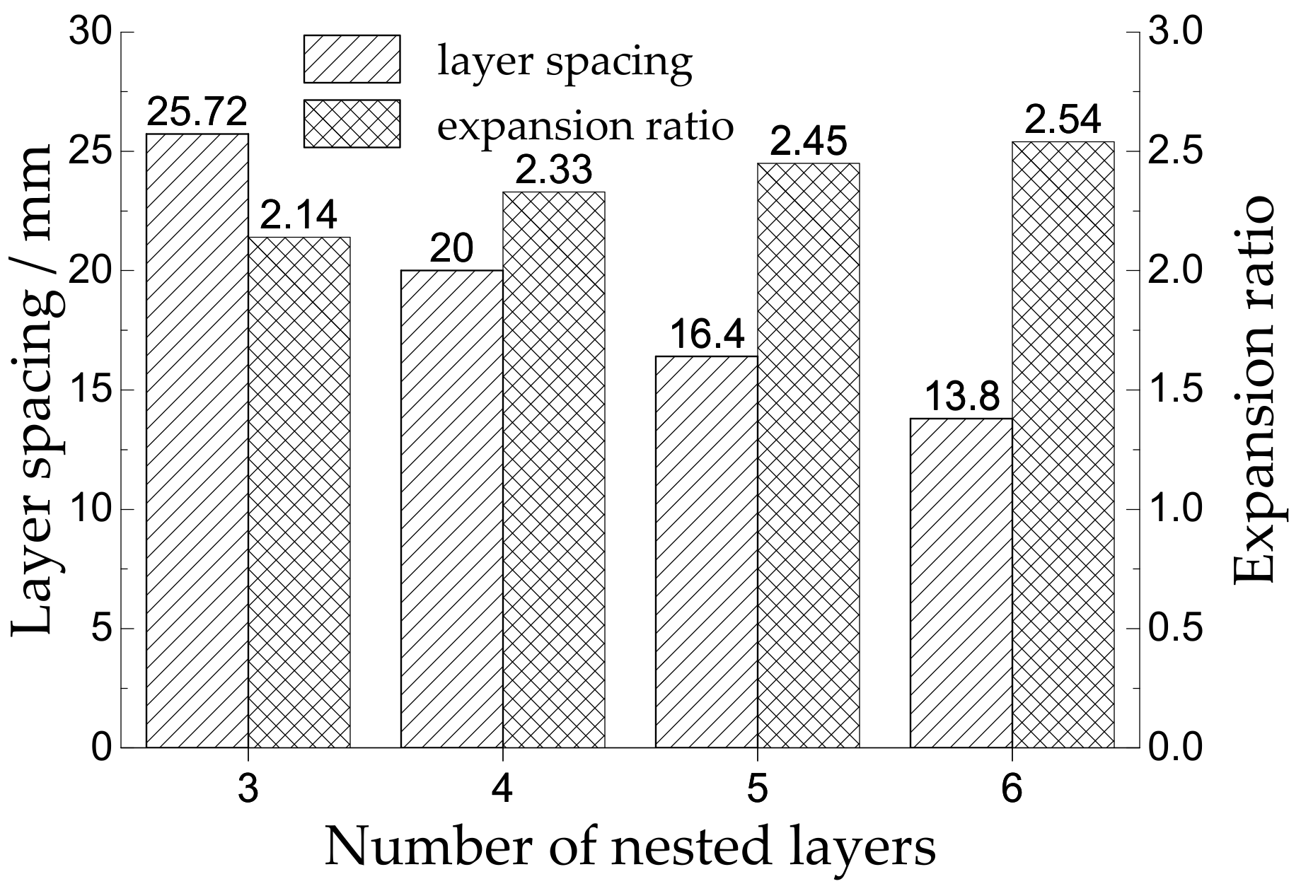
Figure 3 shows the calculated values of the cylindrical layer spacing and expansion ratio of the inlet section when the outer diameter and length of the filter element of the NC-DCP GPF remain unchanged and the number of nested layers of the filter element varies. The expansion ratio of the inlet cone refers to the ratio of the maximum radius to the minimum radius D2/d of sections 6–7 in Figure 2. The pressure drop ΔPjk and ΔPjs of the exhaust flow through the expansion and contraction sections can be calculated via Equation (2) [34].
Δ P j = ζ ρ V ¯ j 2 2
where ρ is the exhaust density, V ¯ j is the average velocity of exhaust entering the inlet or outlet cone, and ζ is the local resistance coefficient. The local resistance coefficient ζ is related to the expansion angle (contraction angle) α and the expansion ratio (contraction ratio) D/d. It is assumed that the expansion angle (contraction angle) α of the NC-DCP GPF model shown in Figure 3 is fixed at 90°. For the inlet cone, the local resistance coefficient ζk can be calculated according to Equation (3) when the expansion angle is 45° < α < 180°.
ζ k = 1 d D 2 2
For the outlet cone, when the contraction angle is 45° < α < 180°, the local resistance coefficient ζs can be calculated according to Equation (4).
ζ s = 0.5 1 d D 2 D d 4 sin α 2 0.5
According to Equations (2) and (3), when the expansion angle is 45° < α < 180°, the pressure drop of exhaust flowing through the inlet cone is not affected by the expansion angle. The larger the expansion ratio is, the greater the pressure drop is. When the outer diameter and the length of the filter element remain unchanged, the number changing of the nested layers of the filter element does not affect the expansion ratio of cross sections 2–3 in the inlet cone shown in Figure 2. Therefore, the pressure drop ΔPjk of the exhaust flow passing through the expansion section of the NC-DCP GPF with different nested layers is the same.
According to Equations (2) and (4), the pressure drop of gas passing through the outlet cone increases with an increased contraction ratio D/d when the contraction angle α of the outlet cone is constant. As shown in Figure 3, the contraction ratio D/d of the outlet cone increases with an increased number of nested layers in the filter element. Therefore, using fewer nested layers is beneficial to reduce the pressure drop (ΔPjs) of the gas passing through the outlet cone of the NC-DCP GPF.
The pressure drop along the annular channel of the exhaust flow through the NC-DCP GPF filter can be calculated via the following Equation (5):
Δ P L = λ L d e ρ V L 2 2
where λ, L, ρ, and VL are the frictional resistance coefficient, the length, the density and the average velocity of the exhaust flow through the annular channel, respectively, de is the equivalent diameter of the annular channel, which is four times that of the hydraulic radius, and de = 2(R − r) for an annular channel with internal and external radius r and R, respectively.
Equation (5) shows that the smaller the equivalent diameter de is, the greater the pressure drop ΔPL is when the length L of the annular channel is constant. In Figure 3, with increasing number of nested layers, the spacing between cylinder layers gradually decreases, that is, the equivalent diameter de gradually decreases. Therefore, a smaller number of nested layers is beneficial for reducing the pressure drop (ΔPL) of the exhaust gas flowing through the filter channel.
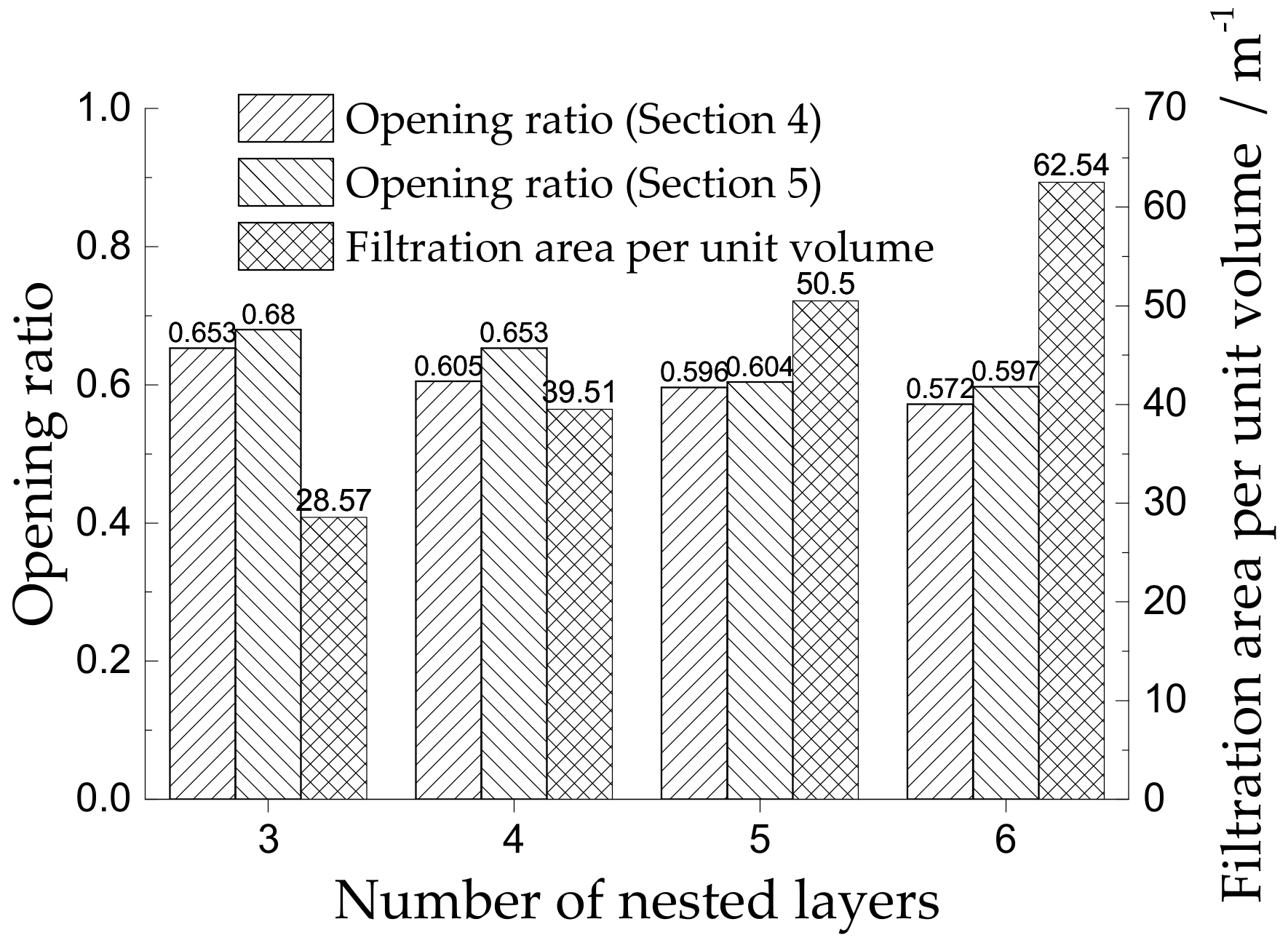
Figure 4 shows the relationship between the opening ratio at both ends and the filtration area per unit volume with the nested layers changing when the overall size of the NC-DCP GPF is unchanged. The opening ratio usually refers to the proportion of the area of the channel inlet surface to the whole cross-sectional area. This ratio can be divided into the opening ratio of the inlet and the outlet.
As shown in Figure 4, with increasing number of nested layers, the opening ratio of sections 4 and 5, as shown in Figure 2, gradually decreases. The opening ratio at both ends of the filter element has an important influence on the pressure drop when the exhaust gas enters and leaves the filter element. Referring to the calculation method of the local pressure drop of the gas flowing in the pipe with a sudden contraction and expansion [4], the calculation equations of the inlet pressure drop ΔPi and outlet pressure drop ΔPo are as follows:
Δ P i = c i 1 δ i ρ V ¯ i 2 2
Δ P o = c o 1 δ o 2 ρ V ¯ o 2 2
where, ci and co are proportional constants whose values depend on the structure of the inlet and outlet of the filter element, respectively, which can be determined by experiments. The inlet opening ratio and outlet opening ratio of the filter element are δi and δo, respectively. The parameter ρ is the exhaust density. The average exhaust velocity at the inlet and outlet of the filter element is V ¯ i and V ¯ o , respectively.
Equations (6) and (7) show that the method to reduce the local pressure drop at the inlet and outlet of the filter element increases the opening ratios of the filter element. Therefore, fewer nested layers are conducive to reducing the local pressure drop when the exhaust enters and leaves the filter.
From Figure 4, when the overall size of the NC-DCP GPF is fixed, a greater number of nested layers corresponds to a larger filtration area per unit volume SF. SF refers to the filtration area provided by the filter wall per unit volume, generally excluding the inner surface area of the micropore in the material. The larger the SF is, the larger the filtration area is, and the smaller the resistance of the filter wall. The exhaust gas passes through the filter medium, which is essentially the flow of gas in the microporous medium, namely, seepage flow. Previous studies have shown that the seepage flow in porous media can be approximated by Darcy’s law [35]. According to Darcy’s law, Equation (8) for calculating the pressure drop caused by gas passing through porous media is as follows:
Δ P w = μ κ w V w h w
where μ, κw, Vw, and hw are the dynamic viscosity of the exhaust gas, the permeability of the porous media, the average velocity of the gas flow through porous media and the thickness of the filter wall, respectively.
Equation (8) shows that when the thickness of the filter wall is constant, the smaller the average velocity of gas passing through the filter wall is, the smaller the pressure drop is. The larger the SF is, the smaller the average velocity of gas passing through the filter wall due to the continuity of exhaust gas is. Therefore, the pressure drop of exhaust gas passing through the porous medium is also smaller. Thus, more nested layers are beneficial for reducing the pressure drop of the porous medium.
To further study the influence of the change in parameters such as the opening ratio, the filtration area per unit and the expansion ratio of the contraction section caused by the number of nested layers on the overall pressure drop of the NC-DCP GPF, a two-dimensional model of the NC-DCP GPF is established based on the geometric model shown in Figure 2, and the internal flow field of the NC-DCP GPF is numerically simulated using the commercial CFD software package Fluent 15.0.

3. Model Formulation

Assuming that the gas flow in the NC-DCP GPF is axisymmetric, a two-dimensional mesh model is generated by choosing half of the model as shown in Figure 2. The model used in this paper does not consider the effects of the heat and mass transfer and the pressure fluctuation in the exhaust pipe and assumes that the velocity distribution of the gas is uniform when it enters the NC-DCP GPF. Then, a two-dimensional axisymmetric steady-state incompressible flow model is established to quantitatively analyze the internal flow characteristics of the CN-DTP GPF. The model has been verified by previous research [35,36].

3.1. Governing Equations of the Flow

For steady-state incompressible two-dimensional flows, the following mass and momentum conservation equations are used to describe the flow (where subscripts i and j represent the directions of the X and Y axes, respectively) [35,36]:
Equation of mass conservation:
ρ u i x i + u j x j = 0
Equation of momentum conservation:
x i ρ u i u j τ i j = p x j + s j
where si and sj are the source terms, indicating the resistance of the filter monolith, and τij is the stress tensor.

3.2. Turbulence Model

When the exhaust enters the NC-DCP GPF, the flow velocity is relatively high. The exhaust flows through the inlet cone, filter element and outlet cone, and a recirculation zone will occur due to the sudden change in the diameter. Therefore, the exhaust exhibits turbulent motion within the NC-DCP GPF. The Reynolds stress to close the flow control equation is calculated by the standard k-ε model. The model includes the turbulence kinetic energy k equation and the turbulence kinetic energy dissipation rate ε equation [37].
x i ρ k u i = x i μ + μ t σ k k x i + G k + G b ρ ε Y M
x i ρ u i ε = x i μ + μ t σ ε k x i C 2 ε ρ ε 2 k + C 1 ε ε k G k + C 3 ε G b
where μt is the turbulent viscosity and μ t = ρ C μ k 2 / ε . Gb is the turbulence kinetic energy generated by buoyancy, Gk is the turbulence kinetic energy generated by the velocity gradient, YM is the turbulence fluctuation by transitional diffusion in compressible turbulence, and C determines how ε is affected by buoyancy. As the buoyancy stress layer is vertical to gravity, C should be zero. The empirical coefficients used in Equation (13) are determined by Table 1 [38].

3.3. Porous Jump Model

The porous jump model is a one-dimensional simplification model of the porous media, which has good robustness and convergence [39]. The porous jump boundary conditions are used to simulate a porous media layer with a finite thickness, with a known velocity and pressure drop. The pressure variation in the gas flow through the porous media layer is defined using a combination of additional internal loss terms and Darcy’s law.
Δ P = μ α u + C 2 1 2 ρ u 2 D m
where u is the velocity component perpendicular to the surface of the porous media, α is the permeability of the porous media, C2 is the porous jump coefficient, and Dm is the thickness of porous media layer. The permeability α and the porous jump coefficient C2 are defined as follows:
α = D p 2 150 ε p 3 1 ε p 2
C 2 = 3.5 D p 1 ε p ε p 3
where Dp is the average pore diameter of the porous medium and ε p is the porosity of the medium.

3.4. Model Volidation

The pressure drop of the NC-DCP GPF is actually the pressure drop between the inlet and outlet when the exhaust passes through the GPF. Therefore, this section describes the validation of the model by comparison with the pressure drop measured in an experiment using the NC-DCP GPF prototype.
The test equipment includes a differential pressure transmitter, an air blower and the NC-DCP GPF prototype. The experimental setup is shown in Figure 5.
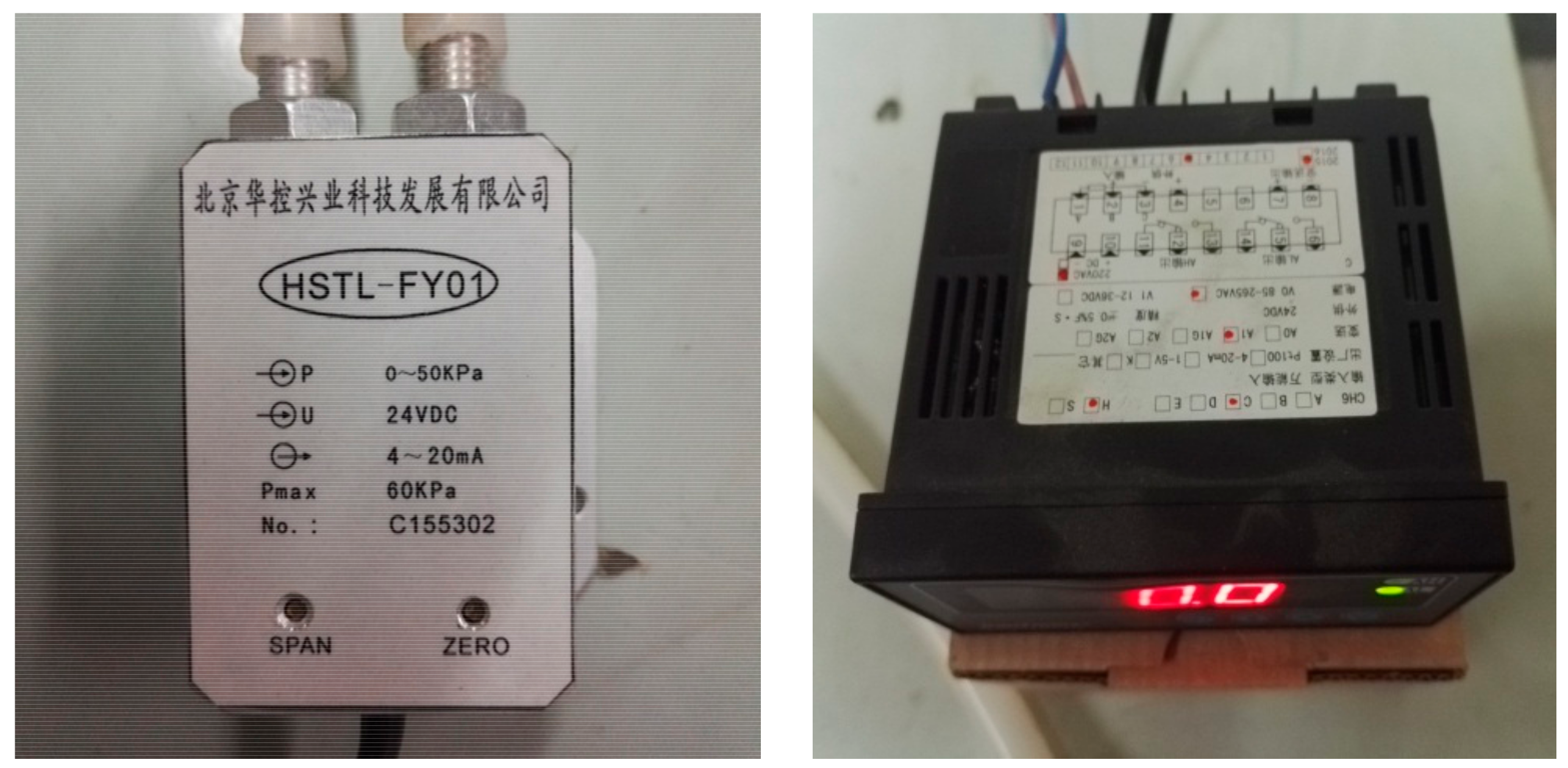
The differential pressure transmitter consists of a differential pressure sensor (HSTL-FY01, ConTronix, Beijing, China) and a digital display (HSTL-CH6, ConTronix, Beijing, China), as shown in Figure 6. The differential pressure sensor has two interfaces, which are connected to the inlet and outlet pipes, respectively, its parameters can been in the Figure 6. The pressure drop between the two interfaces is shown by the digital display.
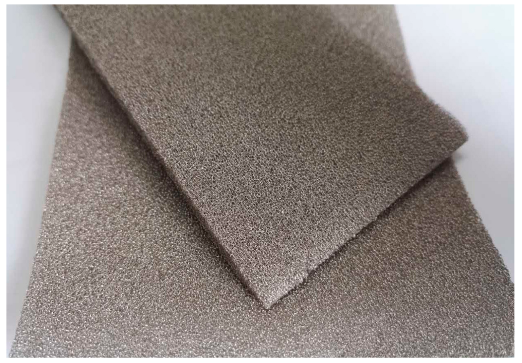
The filter element in the prototype of the NC-DCP GPF is made of porous nickel foam, as shown in Figure 7. The relevant material parameters of the nickel foam from Longsheng Inc. (Shenzhen, China) are shown in Table 2.
The prototype NC-DCP GPF used in the experiment is homemade.
For easy disassembly, the model consists of four parts: the inlet cone, the shell, the filter element, and the outlet cone. The parts are connected by nuts, and a rubber sealing gasket is placed at the joint. To further enhance the sealing of the model, polyester glue is applied on the joints of the assembled parts. Considering the difficulty of fabrication, the filter element is nested by two layers of nickel foam cylinders. Figure 8 shows the components.
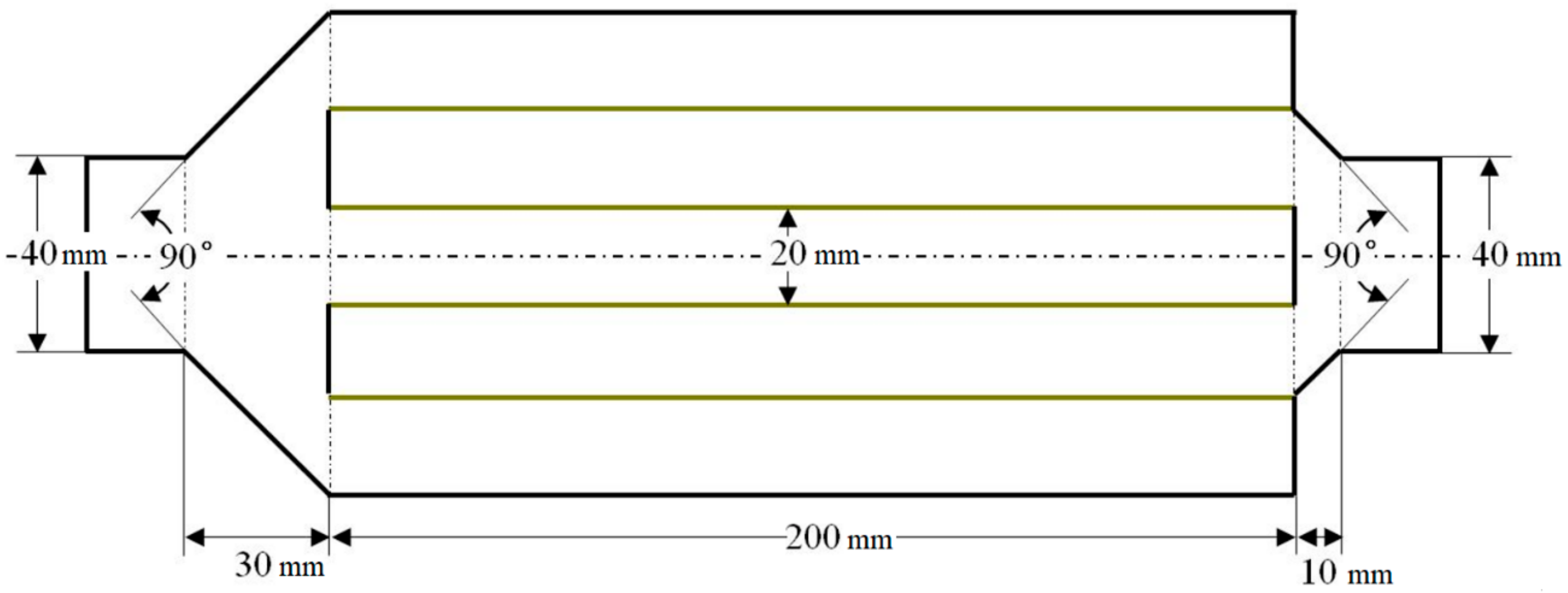
The size of the prototype is shown in Figure 9.
The air source used in the experiment is an adjustable blower. The specifications are shown in Table 3. According to the size of the NC-DCP GPF shown in Figure 8, when the inner diameter of inlet pipe is 40 mm, the flow velocities in the inlet pipe corresponding to the different speeds of the blower are 2, 4, 6, 8, 10, and 12 m/s, respectively.
Assuming that the air enters the prototype from the left side as shown in Figure 9, the flow direction is defined as being in the positive direction, or the negative direction. Table 4 shows the average pressure drop measured from the prototype under the conditions of the two directions and different inlet velocities.
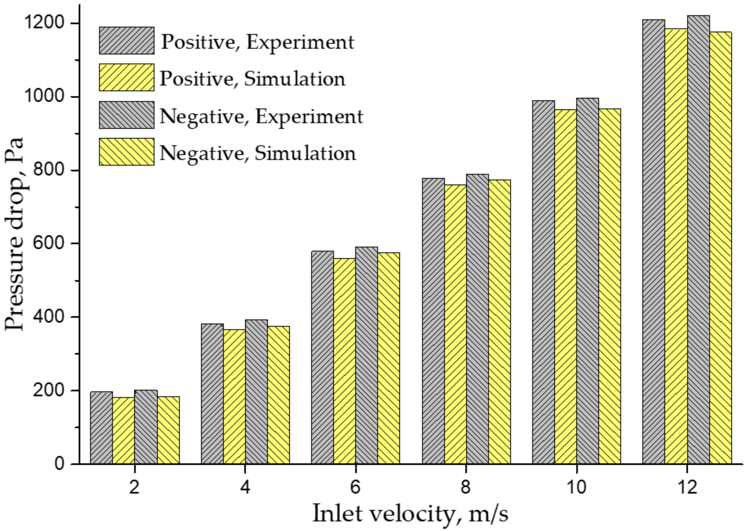
According to the size of the prototype in Figure 9, a two-dimensional grid model is established by Gambit 2.4.6 and simulated by Fluent 15.0. The grid independence was tested based on the pressure drop of the GPF. The grids differed slightly among the different velocities. Taking 2 m/s as an example, grids with 30,439, 35,634, and 40,253 control volumes were used. After the grid test, the pressure drop changed by less than 5% between the final two grids. Thus, the grid with 35,634 control volumes was chosen with a 0.13 mm grid spacing near the filtration wall. Figure 10 shows the comparison between the pressure drop of simulation and the experimental measurements.
It can be seen from Figure 10 that the pressure drop measured for the experimental prototype is in good agreement with the simulation results under different conditions, and the errors are kept within 10%. When the direction is positive, the experimental and simulated pressure drops are all less than the corresponding pressure drop in the negative direction.
Under different conditions, the experimental values are slightly higher than those of the simulation. One reason for this result is that during the process of manufacturing and connecting the prototype, the interface section parts were not made smooth enough, which increases the overall pressure drop to a certain extent.
The other reason concerns the air blower. The air flow provided by the blower fluctuates, and the flow inside the inlet pipe is not uniform on the radial position, which affects the measurement of the pressure drop.

4. Simulation Results and Discussion

4.1. The Effect of the Number of Nested Layers on the Pressure Drop

Two-dimensional grid models of the NC-DCP GPF with 3, 4, 5, and 6 nested layers are established. In the boundary condition setting, assuming that the inlet velocity of the NC-DCP GPF is evenly distributed, the exhaust parameters refer to a GDI engine with a displacement of 2.0 L and a rated speed of 5000 r/min. Considering the different operating conditions of the engine and the inlet exhaust pipe diameter of the NC-DCP GPF, the exhaust level of the inlet section is selected, with average velocities V = 30, 40, and 50 m/s. The exhaust temperature is 750 K, and the exhaust density is 0.6 kg/m3. The outlet boundary is treated as a fully developed flow, the wall is treated as a nonslip boundary condition, and the porous medium is set as a porous jumping boundary condition.
Foam metal has good permeability. Its permeability is allowed to vary within a wide range, generally, 10−12–10−10 m2 and the porosity is between 70% and 80%. Furthermore, foam metal has good workability and can be processed to a thickness of 0.5–10 mm. This paper mainly studies the influence of the structural parameters of the NC-DCP GPF on the overall pressure drop, so the parameters of the filter material are selected and fixed. Based on the parameters of foam metals commonly used as gas filtration materials, the parameters of the porous media are set as follows: the porosity is 0.75, the thickness is 2 mm, the permeability is 1 × 10⁻¹¹ m2, and the corresponding pressure drop coefficient is 140,000 m−1.
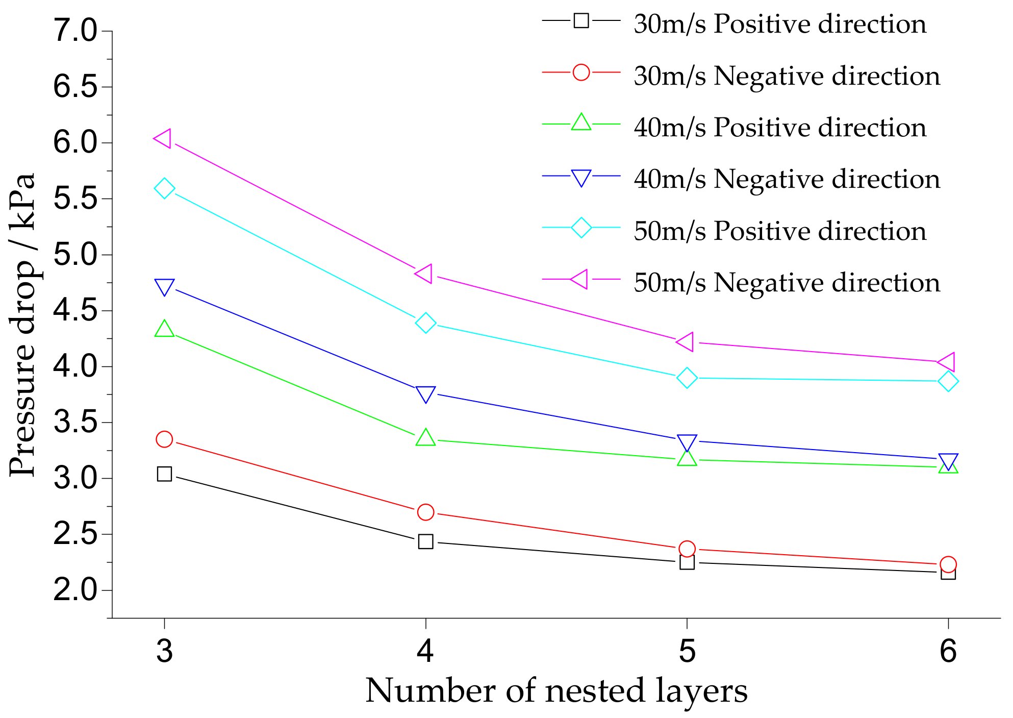
It is assumed that when the exhaust flows from section 1 to section 8 in Figure 2, the direction of air flow is positive, and when it flows from section 8 to section 1, the direction is negative. Figure 11 shows the overall pressure drop across the NC-DCP GPF with different nested layers at different exhaust flow velocities and directions. It can be observed from Figure 11 that the exhaust velocity has a greater impact on the overall pressure drop. The larger the exhaust flow velocity is, the greater the pressure drop is. Under the conditions of 30, 40, and 50 m/s, the overall pressure drop is lower when the flow is in the positive direction.
Figure 11 also shows that the overall pressure drop of the NC-DCP GPF decreases with an increasing number of nested layers, and the amount of the decrease of the overall pressure drop is also reduced. The reason for this phenomenon is that when the overall size is fixed, with an increasing number of nested layers, the spacing of the layers gradually decreases, even though the pressure drop caused by the exhaust passes through the filter decreases. However, the pressure drop along the narrower filter channel increases, so the overall pressure drop of the NC-DCP GPF is not significantly reduced.
The simulation results show that when the exhaust flows from cross-section 1 to cross-section 8, the overall pressure drop of the NC-DCP GPF is smaller, and increasing the number of nested layers can reduce the overall pressure drop.
On the other hand, as the number of nested layers increases, the production cost and difficulty will also increase. Moreover, the spacing between layers will be too small, resulting in narrow filter channels. With the deposition of particles, it is easy to produce blockages and reduce the filtration efficiency. Therefore, a follow-up study to this paper will use the four-layer nested filter element structure shown in Figure 2. The direction of the flow is from cross-section 1 to section 8.

4.2. Optimization of the Diversion Plug and Its Influence

When the exhaust flow enters and exits the filter element, the velocity will change dramatically, which will cause a greater pressure drop. A reasonable design of inlet and outlet structures of filter elements to guide air flow is very important to reduce the overall pressure drop. The local pressure drop at the inlet and outlet of the NC-DCP GPF filter element mainly comes from the annular plugging area, so the installation of diversion plugs in the plugging area is considered to optimize the flow field. In this paper, semicircular and isosceles triangle diversion plugs with cross-sectional shapes are designed. The top angles β of the isosceles triangle diversion plugs are 60°, 90°, and 120°, respectively. The cross-sectional shapes of the diversion plugs are shown in Figure 12.
Assuming that the flow in the NC-DCP GPF filter element is axisymmetric, to study the influence of the diversion plug on the flow field, a two-dimensional model of the filter element with different diversion plugs is established using the NC-DCP GPF filter element shown in Figure 2. The model consists of three exhaust inlet channels. It is assumed that the first, second, and third channels are arranged from the centerline to the border.
In the setting of the boundary conditions, assuming the distribution of the exhaust velocity at the inlet of the filter element is uniform and referring to the exhaust parameters of the GDI engine at the rated speed and the diameter of the exhaust pipe described in Section 3.1, the inlet exhaust velocity is V = 4.4 m/s, and the other exhaust parameters are the same as the inlet boundary conditions shown in Section 3.1. The outlet boundary is treated as fully developed flow, the wall is treated as a nonslip boundary condition, and the filter medium is set as a porous jump boundary condition. Considering that the diversion plug is used to change the flow, the diversion plug is treated as a solid boundary in the model.
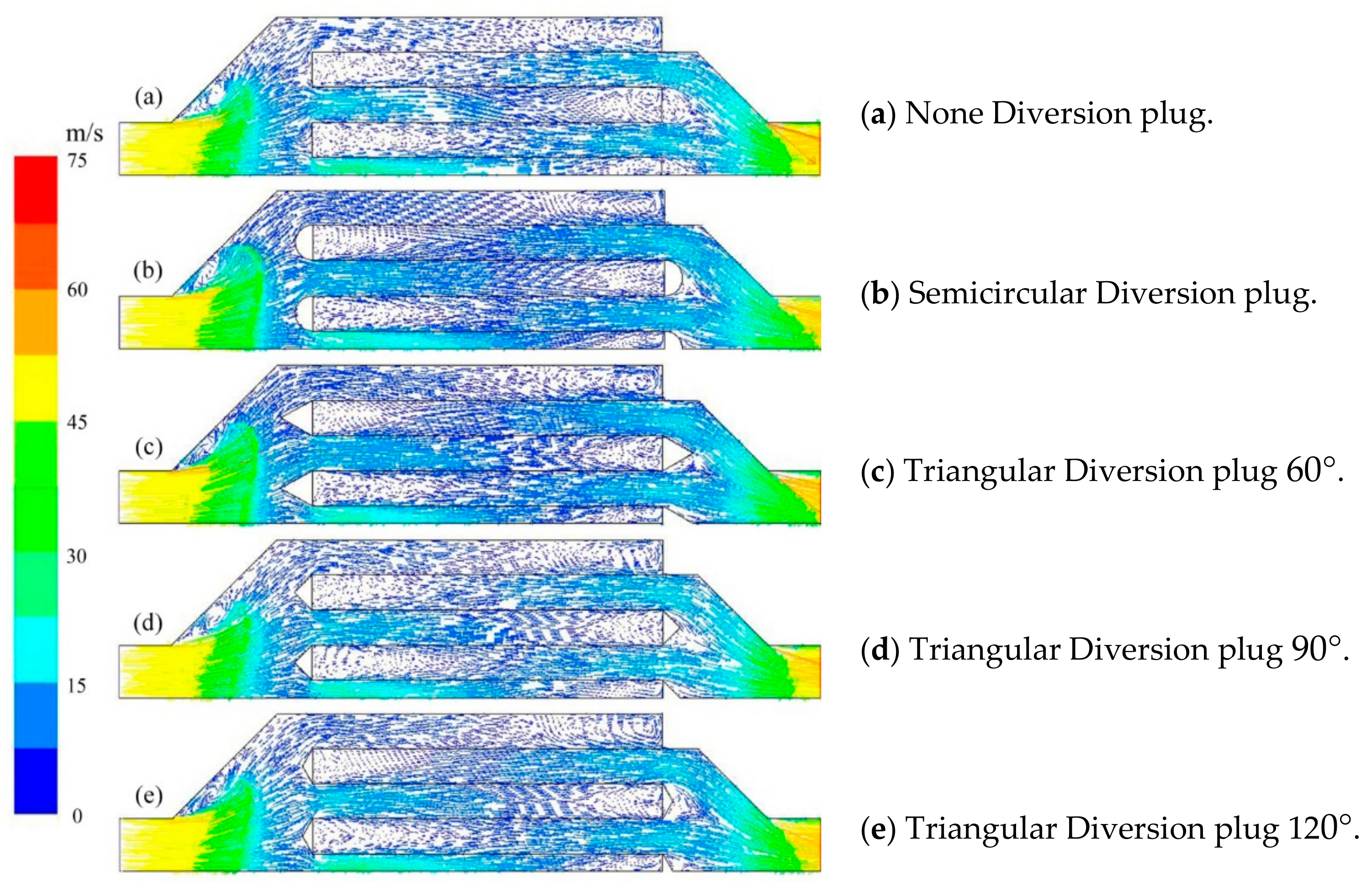
For the GPF without a diversion plug, when air enters the filter element, the direction of the air flow in the annular sealing area will change abruptly, while the diversion plug can weaken the sudden change of the direction of air flow in the area and reduce the pressure drop when the exhaust enters the filter element. The velocity distribution comparison is shown in Figure 13. It can be seen that after the diversion plug is installed, the velocity at the entrance of the filter element decreases, and the direction of the air flow changes more smoothly.
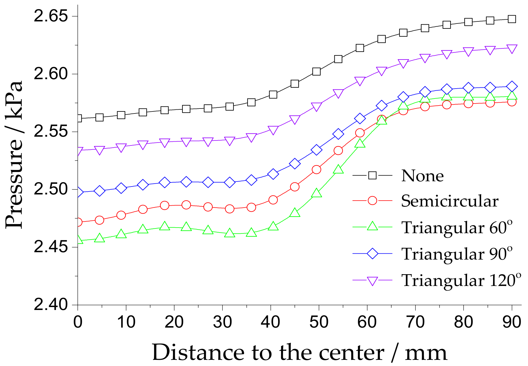
Figure 14 shows the radial pressure distribution at the inlet of the filter element after installing diversion plugs with different cross-sectional shapes. The figure shows that the pressure drop can be significantly reduced by installing diversion plugs. When the cross-sectional shape is an equilateral triangle, i.e., an isosceles triangle with a top angle of 60°, the pressure drop has the largest reduction, up to 4.4% compared to no diversion plug. With an increasing top angle, the pressure drop of the triangle diversion plug gradually decreases. The semicircular diversion plug also obviously reduces the pressure, and the pressure distribution at the inlet is more uniform than that of the 60° triangular diversion plug.
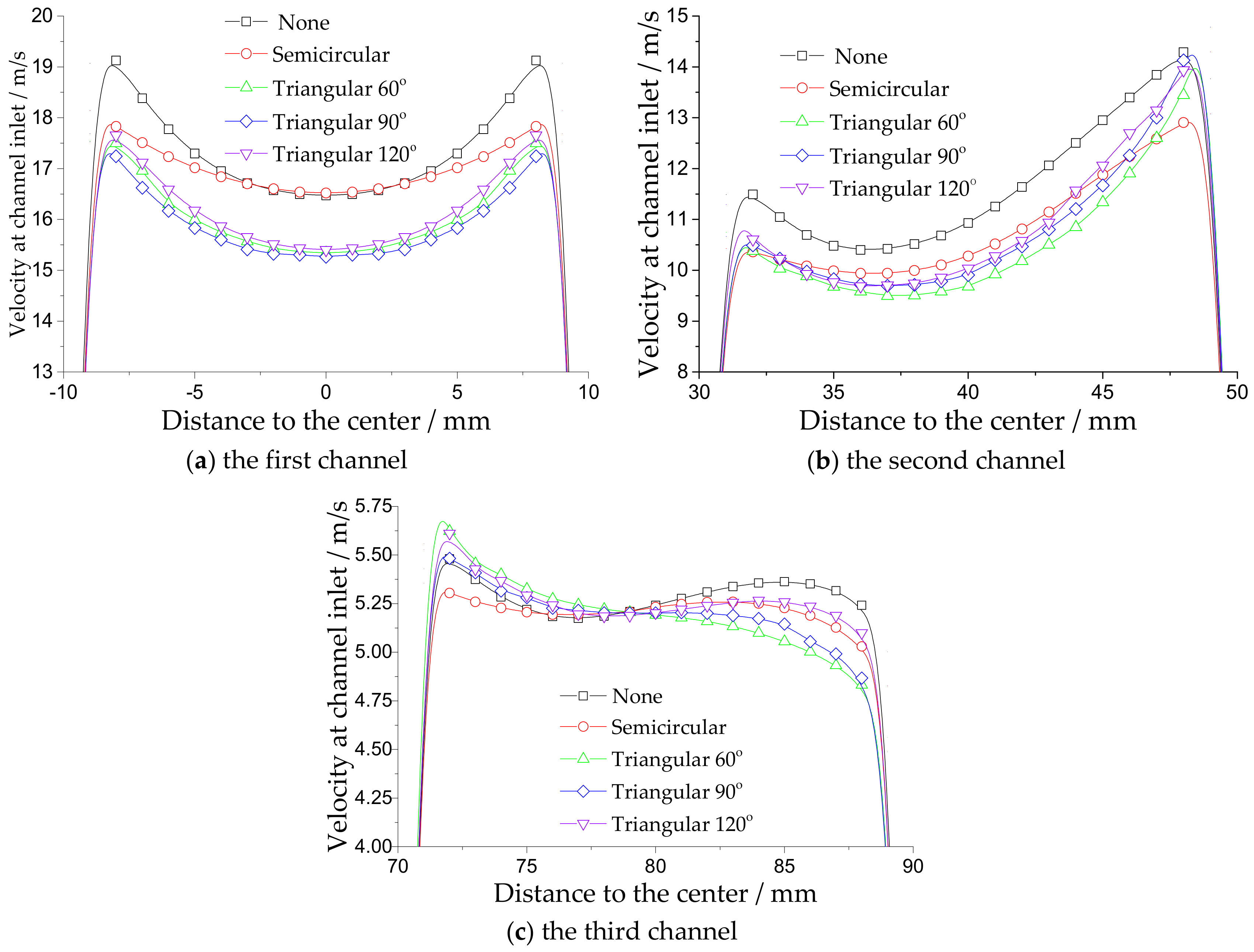
Figure 15 shows the velocity distribution at the inlet cross section of the NC-DCP GPF filter when the exhaust gas enters the channel of the filter element, in which Figure 15a–c show the velocity distributions of the first, second, and third channels of the filter element, respectively. After installation of the diversion plug, the velocity near the inlet central area of each channel has been reduced to varying degrees, the radial velocity distribution is gentler, and the difference between the maximum and minimum velocities near the center of the channel is smaller. From Figure 15a,b, the minimum velocities of the first and second channels appear near the center of the channel. The reduction degree of the triangular diversion plug is greater than that of the semicircular structure, and the smaller the angle of the triangle top angle, the greater the decrease degree of the inlet velocity of the channel. The flow field in the channel is only affected by the diversion plug on one side, as shown in Figure 15c. The installation of the diversion plug reduces the air velocity on one side of the wall flow but slightly increases the velocity on the other side. According to Figure 15, in the absence of a diversion plug, the velocities in the first and second channels are larger, and the larger exhaust velocity increases the filter pressure on the filter wall of the inner channel.
Therefore, installation of a diversion plug can significantly reduce the velocity in the channel, especially on the side close to the center, which causes more gas to enter the outer filter wall with a larger filtration area, which is conducive to the purification of the exhaust gas.
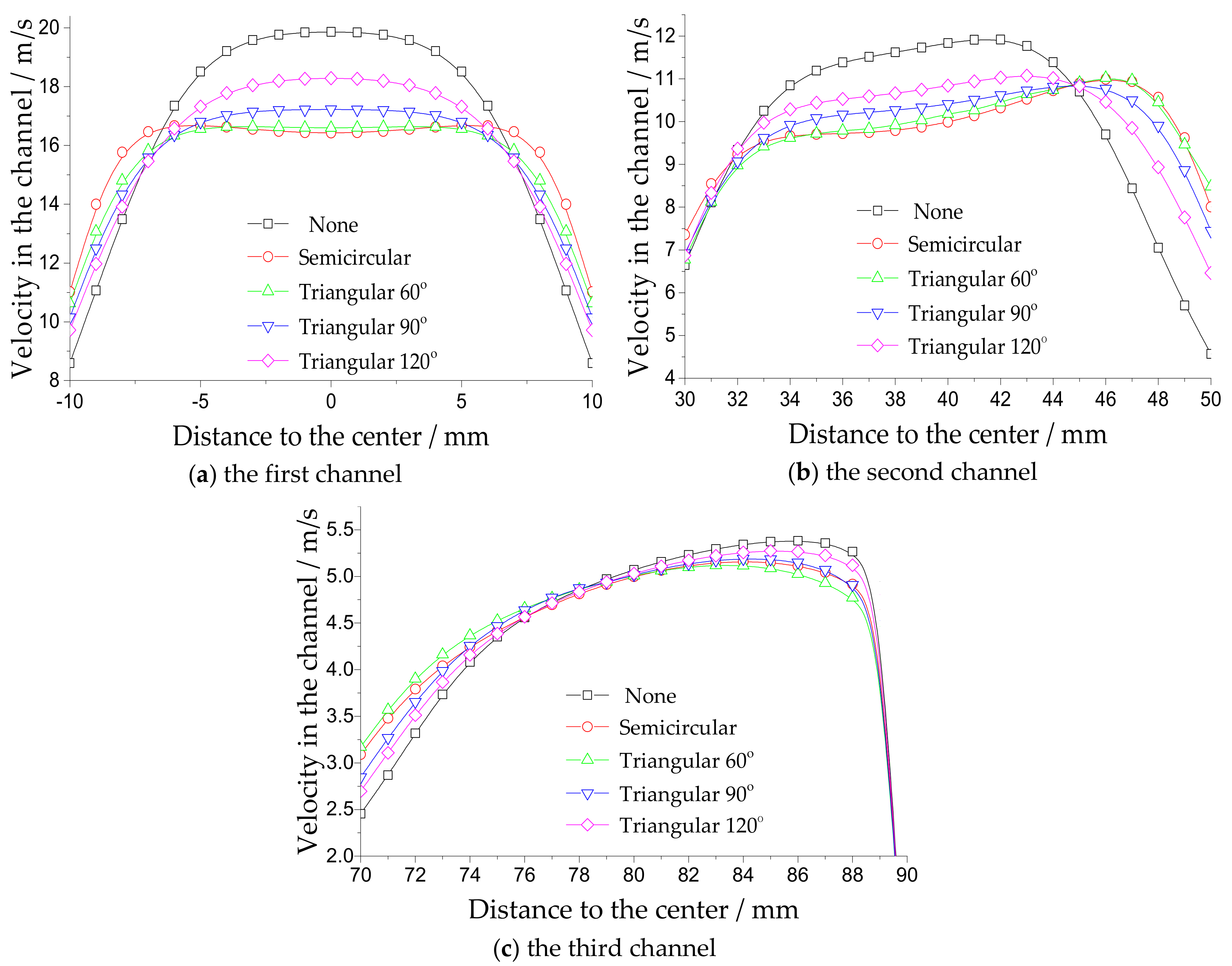
To further investigate the influence of the diversion plug on the flow uniformity in the channel, the velocity field distribution at 20 mm from the entrance of the channel is studied, as shown in Figure 16.
In Figure 16, the diversion plug reduces the maximum velocity in the three channels of the filter element and improves the minimum velocity to render the velocity field inside the filter element more uniform. For the triangular diversion plug studied in this paper, the smaller the apex angle is, the greater the reduction of the maximum velocity and the increase in the minimum velocity are. As shown in Figure 16a,b, in the first and second channels, the maximum velocity reduction and minimum velocity increase of the semicircular diversion plug are greater than those of the triangular diversion plug. In the third channel, as shown in Figure 16c, the maximum velocity reduction and minimum velocity increase of the semicircular diversion plug are also more significant and are second only to the effects of the isosceles triangular cross-sectional diversion plug with a top angle of 60°.
The essence of the diversion plug is to guide the exhaust flow to cause the exhaust gas to smoothly enter the filtering channel, such that the flow field distribution can be more uniform. To quantitatively analyze the uniformity of the internal flow field of the NC-DCP GPF, an evaluation index of the flow field uniformity was introduced. The flow uniformity index is generally expressed by a criterion established by Weltens et al. [40] for evaluating the velocity distribution in the filter element, as shown in Equation (17).
γ = 1 1 2 n i n v i v m e a n 2 v m e a n
where γ is the flow uniformity index, the higher value illustrates better flow uniformity; n is the number of measurement points; and v m e a n is the average velocity inside the channel.
Table 5 reports the flow uniformity index before and after the installation of the diversion plug shown in Figure 15. The uniformity of the flow field inside the filter element is significantly improved after the diversion plug is installed. The semicircular diversion plug increases the flow uniformity of the first channel and the second channel by 6.5% and 6.2%, respectively, and the flow uniformity of the third channel is also improved, but it is slightly smaller than that of the triangular diversion plug with an apex angle of 60°. For the triangular diversion plug, the smaller the apex angle, the more significant the improvement in the flow uniformity inside the channel.

5. Conclusions

In this paper, a novel wall-flow GPF consisting of foam metal cylinders and diversion plugs nested inside each other is designed. The filter element forms an annular filter channel by the nested cylinder and forces the airflow to pass through the filter wall surface through the interval plugs. The advantages of the filter are its small size, light weight, compact structure, large filtering surface area, and small flow resistance. The choice of foam metal as the filter material not only ensures the high filtration efficiency of the NC-DCP GPF but also meets the long-term high-temperature working conditions.
The main structural parameters of the NC-DCP GPF element is the number of nesting layers of the cylinder. Under the condition in which the overall size of the NC-DCP GPF is constant, the number of nesting layers affects the spacing between layers, the opening ratio and the filtration area, thus affecting the overall pressure drop of the NC-DCP GPF. The greater the number of nesting layers is, the larger the filtration area is, and the smaller the pressure drop is. However, as the number of nesting layers increases, the nesting layers have less influence on the overall pressure drop of the NC-DCP GPF, because the pressure drop caused by the friction along the channel increases, along with the effects of the smaller spacing between the layers and narrower filter channels.
The diversion plug of the NC-DCP GPF affects the pressure drop of the filter element. The isosceles triangular diversion plug with an apex angle of 60° has the greatest pressure drop reduction compared to no plug, followed by the semicircular diversion plug. The diversion plug can also influence the distribution of the internal flow filed, it decreases the inlet velocity of the inner channel. The triangular diversion plug reduces the inlet velocity of the inner channel more than that of the semicircular structure and the smaller the apex angle is, the greater the decrease in the inlet velocity of the channel is. The diversion plug improves the flow uniformity of the flow field inside the NC-DCP GPF and renders the flow distribution inside each filter channel more uniform. The semicircular diversion plug exhibits the greatest improvement in the uniformity index of the flow field in the inner channel, and the improvement in the uniformity index of the flow field in the outer channel of the filter element is second only to that from the triangular diversion plug with an apex angle of 60°. In the triangular diversion plug, the smaller the apex angle is, the greater the improvement in the flow field uniformity index is.

Author Contributions

Conceptualization, M.M. and X.L.; methodology, M.M. and X.L.; software, M.M. and Y.Q.; validation, M.M. and Y.Q.; formal analysis, M.M.; writing—original draft preparation, Y.Q.; writing—review and editing, M.M. and Y.S.; supervision, X.L.; project administration, X.L. and Y.Q.

Funding

This research was funded by The National Key Research and Development Program of China, grant number: 2017YFB0103402 and 2018YFB0104103. This work is supported in part by a scholarship from the China Scholarship Council (CSC) under Grant File No. 201706020106.

Conflicts of Interest

The authors declare no conflict of interest.

References

  1. Davis, S.C.; Williams, S.E.; Boundy, R.G.; Moore, S.M. Vehicle Technologies Market Report; Oak Ridge National Laboratory: Oak Ridge, TN, USA, 2016.
  2. Zhao, F.; Harrington, D.L.; Lai, M.-C.D. Automotive Gasoline Direct-Injection Engines; SAE International: Warrendale, PA, USA, 2002. [Google Scholar]
  3. Bandel, W.; Fraidl, G.K.; Kapus, P.E.; Sikinger, H.; Cowland, C.N. The turbocharged GDI engine: Boosted synergies for high fuel economy plus ultra-low emission. SAE Tech. Pap. 2006, 1, 1266. [Google Scholar]
  4. Woldring, D.; Landenfeld, T.; Christie, M.J. DI boost: Application of a high performance gasoline direct injection concept. SAE Tech. Pap. 2007, 1, 1410. [Google Scholar]
  5. Davis, R.S.; Mandrusiak, G.D.; Landenfeld, T.; Davis, R.S.; Mandrusiak, G.D.; Landenfeld, T.; Davis, R.S.; Mandrusiak, G.D.; Landenfeld, T.; Davis, R.S. Development of the combustion system for general motors’ 3.6L DOHC 4V V6 engine with direct injection. SAE Int. J. Engines 2008, 1, 85–100. [Google Scholar] [CrossRef]
  6. Johnson, T.; Joshi, A. Review of vehicle engine efficiency and emissions. SAE Int. J. Engines 2018, 11, 1307–1330. [Google Scholar] [CrossRef]
  7. Spicher, U.; Reissing, J.; Kech, J.M.; Gindele, J. Gasoline direct injection (GDI) engines—Development potentialities. SAE Tech. Pap. 1999, 1, 2938. [Google Scholar]
  8. Aakko, P.; Nylund, N.-O. Particle emissions at moderate and cold temperatures using different fuels. SAE Tech. Pap. 2003, 1, 3285. [Google Scholar]
  9. Wu, G.; Kuznetsov, A.V.; Jasper, W.J. Distribution characteristics of exhaust gases and soot particles in a wall-flow ceramics filter. J. Aerosol Sci. 2011, 42, 447–461. [Google Scholar] [CrossRef]
  10. Mohr, M.; Forss, A.-M.; Steffen, D. Particulate emissions of gasoline vehicles and influence of the sampling procedure. SAE Tech. Pap. 2000, 1, 1137. [Google Scholar]
  11. Graskow, B.R.; Kittelson, D.B.; Ahmadi, M.R.; Morris, J.E. Exhaust particulate emissions from a direct injection spark ignition engine. SAE Trans. 1999, 108, 602–609. [Google Scholar]
  12. Raza, M.; Chen, L.F.; Leach, F.; Ding, S.T. A review of particulate umber (PN) emissions from gasoline direct injection (GDI) engines and their control techniques. Energies 2018, 11, 1417. [Google Scholar] [CrossRef]
  13. Platt, S.M.; El Haddad, I.; Pieber, S.M.; Zardini, A.A.; Suarez-Bertoa, R.; Clairotte, M.; Daellenbach, K.R.; Huang, R.J.; Slowik, J.G.; Hellebust, S.; et al. Gasoline cars produce more carbonaceous particulate matter than modern filter-equipped diesel cars. Sci. Rep. 2017, 7, 4926. [Google Scholar] [CrossRef]
  14. Tandon, P.; Heibel, A.K.; Whitmore, J.; Kekre, N.; Chithapragada, K. Measurement and prediction of filtration efficiency evolution of soot loaded diesel particulate filters. Chem. Eng. Sci. 2010, 65, 4751–4760. [Google Scholar] [CrossRef]
  15. Jiaqiang, E.; Pham, M.; Zhao, D.; Deng, Y.; Le, D.; Zuo, W.; Zhu, H.; Liu, T.; Peng, Q.; Zhang, Z. Effect of different technologies on combustion and emissions of the diesel engine fueled with biodiesel: A review. Renew. Sustain. Energy Rev. 2017, 80, 620–647. [Google Scholar]
  16. Chan, T.W.; Lax, D.; Gunter, G.C.; Hendren, J.; Kubsh, J.; Brezny, R. Assessment of the fuel composition impact on black carbon mass, particle number size distributions, solid particle number, organic materials, and regulated gaseous emissions from a light-duty gasoline direct injection truck and passenger car. Energy Fuels 2017, 31, 10452–10466. [Google Scholar] [CrossRef]
  17. Merkel, G.A.; Cutler, W.A.; Warren, C.J. Thermal durability of wall-flow ceramic diesel particulate filters. SAE Trans. 2001, 110, 168–182. [Google Scholar]
  18. Boger, T.; Rose, D.; Nicolin, P.; Gunasekaran, N.; Glasson, T. Oxidation of soot (Printex® U) in particulate filters operated on gasoline engines. Emiss. Control Sci. Technol. 2015, 1, 49–63. [Google Scholar] [CrossRef]
  19. Bhattacharya, A.; Calmidi, V.V.; Mahajan, R.L. Thermophysical properties of high porosity metal foams. Int. J. Heat Mass Transf. 2002, 45, 1017–1031. [Google Scholar] [CrossRef]
  20. Incera Garrido, G.; Patcas, F.C.; Lang, S.; Kraushaar-Czarnetzki, B. Mass transfer and pressure drop in ceramic foams: A description for different pore sizes and porosities. Chem. Eng. Sci. 2008, 63, 5202–5217. [Google Scholar] [CrossRef]
  21. Myung, C.L.; Kim, J.; Jang, W.; Jin, D.; Park, S.; Lee, J. Nanoparticle filtration characteristics of advanced metal foam media for a spark ignition direct injection engine in steady engine operating conditions and vehicle test modes. Energies 2015, 8, 1865–1881. [Google Scholar] [CrossRef]
  22. Sosnick, B. Process for Making Foam Like Mass of Metal. U.S. Patent 2,434,775, 20 January 1948.
  23. Kamath, P.M.; Balaji, C.; Venkateshan, S.P. Convection heat transfer from aluminium and copper foams in a vertical channel—An experimental study. Int. J. Therm. Sci. 2013, 64, 1–10. [Google Scholar] [CrossRef]
  24. Masoudi, M.; Konstandopoulos, A.G.; Nikitidis, M.S.; Skaperdas, E.; Zarvalis, D.; Kladopoulou, E.; Altiparmakis, C. Validation of a model and development of a simulator for predicting the pressure drop of diesel particulate filters. SAE Trans. 2001, 110, 650–656. [Google Scholar]
  25. Konstandopoulos, A.G.; Skaperdas, E.; Masoudi, M. Inertial contributions to the pressure drop of diesel particulate filters. SAE Tech. Pap. 2001. [Google Scholar] [CrossRef]
  26. Haralampous, O.A.; Kandylas, I.P.; Koltsakis, G.C.; Samaras, Z.C.; Haralampous, O.A. Diesel particulate filter pressure drop Part 1: Modelling and experimental validation. Int. J. Engine Res. 2004, 5, 149–162. [Google Scholar] [CrossRef]
  27. Masoudi, M. Pressure drop of segmented diesel particulate filters. SAE Trans. 2005, 114, 503–511. [Google Scholar]
  28. Bermúdez, V.; Serrano, J.; Piqueras, P.; Sanchis, E. On the impact of particulate matter distribution on pressure drop of wall-flow particulate filters. Appl. Sci. 2017, 7, 234. [Google Scholar] [CrossRef]
  29. Torregrosa, A.J.; Serrano, J.R.; Arnau, F.J.; Piqueras, P. A fluid dynamic model for unsteady compressible flow in wall-flow diesel particulate filters. Energy 2011, 36, 671–684. [Google Scholar] [CrossRef] [Green Version]
  30. Ma, L.; Paraschivoiu, M.; Yao, J.; Blackman, L. Improving flow uniformity in a diesel particulate filter system. SAE Tech. Pap. 2001. [Google Scholar] [CrossRef]
  31. Howitt, J.S.; Sekella, T.C. Flow effects in monolithic honeycomb automotive catalytic converters. SAE Trans. 1974, 83, 1067–1075. [Google Scholar]
  32. Bella, G.; Rocco, V.; Maggiore, M. A study of inlet flow distortion effects on automotive catalytic converters. J. Eng. Gas Turbines Power 1991, 113, 419. [Google Scholar] [CrossRef]
  33. Qiu, Y.; Li, X.; Mu, M.; Li, X. Structure design and parameter optimization of new GPF based on FLUENT. Comput. Aided Eng. 2017, 26, 19–24. [Google Scholar]
  34. Persoons, T. Experimental Flow Dynamics in Automotive Exhaust Systems with Close-Coupled Catalyst. Ph.D. Thesis, Catholic University of Leuven, Leuven, Belgium, 2006. [Google Scholar]
  35. Mu, M.; Li, X.; Aslam, J.; Qiu, Y.; Yang, H.; Kou, G.; Wang, Y. A study of shape optimization method on connection cones for diesel particulate filter (DPF). In Proceedings of the ASME 2016 International Mechanical Engineering Congress and Exposition, Phoenix, AR, USA, 11–17 November 2016; p. V012T16A001. [Google Scholar]
  36. Mu, M.; Sjöblom, J.; Ström, H.; Li, X. Analysis of the flow field from connection cones to monolith reactors. Energies 2019, 12, 455. [Google Scholar] [CrossRef]
  37. Zhang, Z.; Yang, S.L.; Johnson, J.H. Modeling and numerical simulation of diesel particulate trap performance during loading and regeneration. SAE Trans. 2002, 111, 471–483. [Google Scholar]
  38. Shuai, S.; Wang, J.; Zhuang, R. Application of CFD to the optimal design of automotive catalytic converyers. Automot. Eng. 2000, 22, 129–133. [Google Scholar]
  39. Chandesris, M.; Jamet, D. Derivation of jump conditions for the turbulence model at a fluid/porous interface. Int. J. Heat Fluid Flow 2009, 30, 306–318. [Google Scholar] [CrossRef]
  40. Weltens, H.; Bressler, H.; Terres, F.; Neumaier, H.; Rammoser, D. Optimisation of catalytic converter gas flow distribution by CFD prediction. SAE Tech. Pap. 1993. [Google Scholar] [CrossRef]
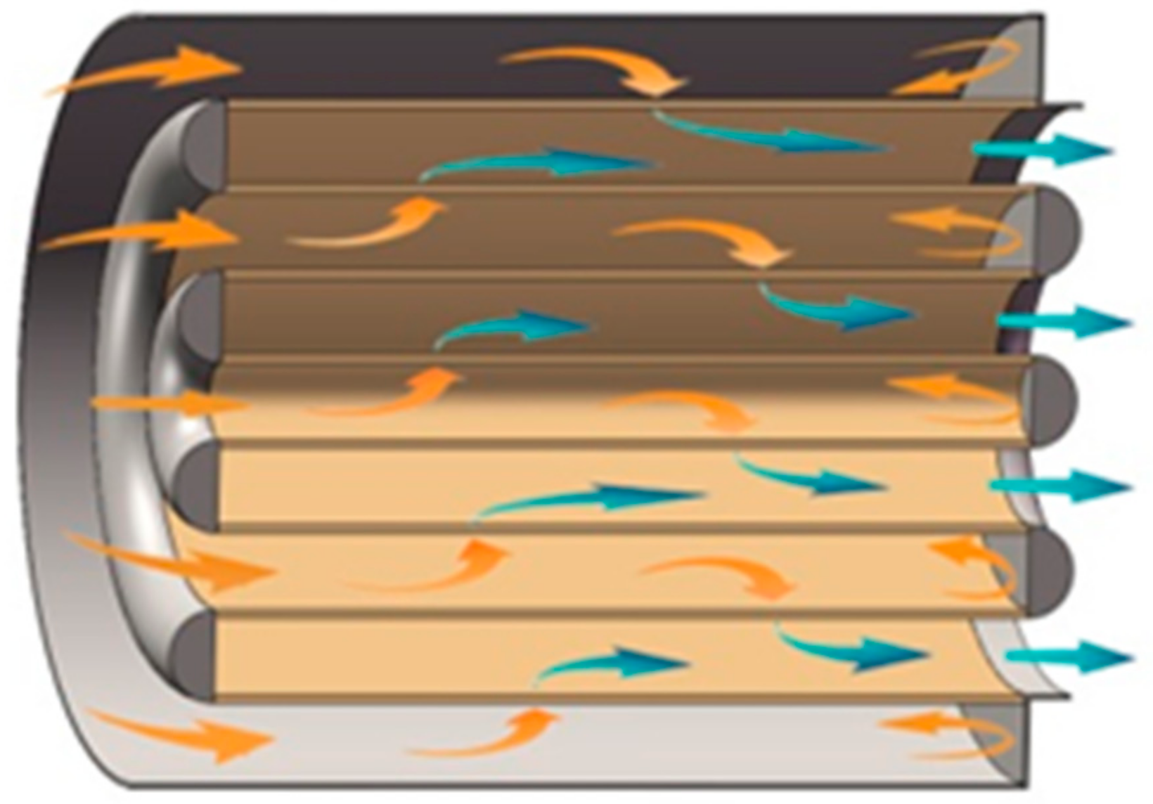
Figure 1. Schematic of filter element.
Energies 12 02045 g001
Figure 2. Profile structure of the nested cylinder and diversion channel plug (NC-DCP) gasoline particulate filter (GPF).
Energies 12 02045 g002
Figure 3. The spacing and the expansion ratio of the NC-DCP GPF.
Energies 12 02045 g003
Figure 4. Opening rate and filtration area of the NC-DCP GPF filter element.
Energies 12 02045 g004
Figure 5. Schematic of the experimental setup.
Energies 12 02045 g005
Figure 6. Differential pressure sensor (left) and the digital display (right).
Energies 12 02045 g006
Figure 7. Nickel foam.
Energies 12 02045 g007
Figure 8. Prototype of the NC-DCP GPF.
Energies 12 02045 g008
Figure 9. The size of the NC-DCP GPF prototype.
Energies 12 02045 g009
Figure 10. The pressure drop comparison for model validation.
Energies 12 02045 g010
Figure 11. The pressure drop of the NC-DCP GPF with different numbers of nested layers.
Energies 12 02045 g011
Figure 12. Diversion plugs with different cross sections.
Energies 12 02045 g012
Figure 13. Velocity distribution.
Energies 12 02045 g013
Figure 14. Radial pressure distribution at the entrance of the channels.
Energies 12 02045 g014
Figure 15. Velocity distribution at the annular channel entrance of the NC-DCP GPF.
Energies 12 02045 g015
Figure 16. Velocity distribution in the annular channel of the NC-DCP GPF.
Energies 12 02045 g016
Table 1. Empirical factors for k-ε equation.
σkσεCCCμ
1.01.31.441.920.09
Table 2. Parameters of the Nickel foam.
Thickness, mmMean Pore Diameter, mmPorosityPermeability, m2Factor of Porous Jump C2, m−1
20.340.751 × 10−1114,000
Table 3. Specification parameters of the air blower.
TypeSpeed, r/minAir Volume, m2/minPower, W
Q1B-XP-2.50–16,0003.51200
Table 4. Pressure drop of the GPF prototype.
Inlet Velocity, m/sPressure Drop, Pa
PositiveNegative
2196.5201.6
4382.2392.2
6579.0591.8
8778.5790.0
10989.0995.5
1212101221
Table 5. Flow uniformity index of flow in annular channels.
Cross-Sectional Shape of Diversion Plug in the NC-DCP GPF ElementFlow Uniformity Index
First ChannelSecond ChannelThird Channel
none0.90820.91190.9282
semicircular0.96690.96880.9501
triangular (apex angle = 60°)0.95760.96570.9550
triangular (apex angle = 90°)0.94640.96170.9443
triangular (apex angle = 120°)0.93170.94970.9374