Article

CFD Analysis of a Buffer Tank Redesigned with a Thermosyphon Concentrator Tube

1
Defense University Center, Spanish Naval Academy, Plaza de España s/n 36900 Marín, Spain
2
Industrial Engineering School, University of Vigo, Lagoas-Marcosende s/n 36310 Vigo, Spain
*
Author to whom correspondence should be addressed.
Energies 2019, 12(11), 2162; https://doi.org/10.3390/en12112162
Submission received: 15 April 2019 / Revised: 15 May 2019 / Accepted: 4 June 2019 / Published: 5 June 2019
(This article belongs to the Section D: Energy Storage and Application)

Abstract

:
This study analyzes a buffer tank simulated in both continuous operation mode and heating mode using CFD techniques. The analysis is focused in the thermal behavior of the tank, especially in parameters such as heat exchanged, heating time, and temperature distributions into the tank, in order to propose a better design. The results of the different simulations show that the tank heats water extremely slowly and extremely evenly when producing domestic hot water (DHW), which negatively affects the thermal stratification that is critical for rapidly reaching the DHW temperature. Therefore, the main problem of the tank is an inefficient heat exchange and a poor distribution of temperature. In order to overcome these operational limitations, a new design is proposed by installing a tube inside the tank that encloses the heating coil and sends hot water directly to the tank top region such that high-temperature DHW is rapidly provided, and thermal stratification is improved. Several simulations are performed with different open and closed configurations for the outlets of the inner tube. The different results show that the heating times significantly improve, and the time needed to reach the 45 °C set point temperature is reduced from 44 to 15 min. In addition, the simulations in which the opening and closing of the water outlets are regulated, the outlet DHW temperature is kept within 45–60 °C, which prevents overheating to unsafe use temperatures. Furthermore, the results of the simulation in continuous operation mode show a clear improvement of thermal stratification and an increase in the heat transmitted to the inside of the tank.

1. Introduction

Domestic hot water (DHW) is extremely important in the consumption of domestic energy. This energy production and storage must fulfil some requirements to guarantee efficiency and comfort, such as a rapid heating and an operating temperature in the range of 45–50 °C. Buffer tanks are typically used as a hot water storage system that meets these comfort characteristics. These tanks allow us to accumulate significant amounts of DHW and prevent intermittent operation of boilers, which can produce a decrease of the operating performance.
Thermal stratification directly influences heat transfer and accumulation efficiency of the tank [1,2] since the heat exchangers are located in the lowest area of the tank. An additional advantage of thermal stratification is the reduction of heating times since the DHW outlet is located at the top of the tank where hot water is accumulated. Natural buoyancy flow is critical for thermal stratification, which has been studied exhaustively in reference [3] for systems with different geometries. Ievers and Lin reference [4] studied the influence of geometrical parameters of the tank and inlets location on the thermal stratification. Kang [5] studied how hot water mixes during the heating process by conducting experimental tests in which the orientations of the heat exchanger tubes were varied. Dragsted et al. [6] studied how performance is improved by thermal stratification by changing the height of hot water inlets.
Computational fluid dynamics (CFD) is currently applied for the study of a variety of systems. This allows us to analyze a great number of parameters with high accuracy and to predict behavior without performing experimental testing. However, the use of CFD for the study of buffer tanks has not occurred. A few works studied the effect of design on thermal stratification. Bouhal et al. [7] studied thermal stratification through simulations of a tank with different locations water inlets and deflectors. Abdelhak et al. [8] performed CFD modeling to study the stratification characteristics on the tank discharge for different positions. Arslan and Igci [9] performed transitional simulations of accumulated hot water discharges to analyze the main parameters that influence the storage efficiency. Fan et al. [10] experimented and simulated a tank with an internal pipe that improves the thermal stratification by injecting the heated water in the upper region of the tank. Wang et al. [11] applied CFD models to design more efficient tanks and improve stratification on hot water storage tanks; the authors used a deflector that prevent the mixing caused by the water entering and disrupting stratification.
This theoretical study simulates the operation of a buffer tank working as a heat exchanger and in DHW accumulation mode in order to improve thermal behavior and stratification performance. The simulation is based on the CFD models proposed in the authors’ previous study [12]. The results of this work showed a reasonably good agreement with the experiments. Because the results demonstrated an extremely low stratification degree and extremely long DHW heating times, a redesign to improve these parameters is proposed. This design consists of an internal tube, where the heating coil is located, that concentrates the thermosyphon effect and increases the buoyancy flow.

2. Mode Description

All the simulations performed in this work were run with the solver Ansys Fluent 15.0. The solutions are obtained by numerically solving the Navier-Stokes transport equations. The SIMPLE algorithm was used to couple the pressure and momentum equations. In addition, an energy conservation equation is solved to yield the temperature field in the entire computational domain. These equations are detailed as described by Patankar [13].
The SST k-ω model was used to model turbulence. The advantage of this model is that at low fluid velocities, the model converges to a laminar behavior in the near wall zone. The tank studied in this work operates with natural convection. Therefore, low Reynolds numbers are expected in most of the tank volume. This model is also commonly used in the literature [12,14,15] due its relatively low computational cost and high stability. The shear stress in the near wall regions is solved through the “law of the wall”, which follows a logarithmic function that depends on the “y+”, which is a dimensionless parameter that represents the distance to the wall. The law of the wall was described in detail by Versteeg and Malalasequera [16].
A second-order-upwind discretization was applied for momentum and energy equations and first-order-upwind was used for turbulence equations, since second order is very unstable for their convergence. The PRESTO algorithm was used for pressure.
The Boussinesq approximation is used to represent the natural convection processes in the fluid, since it results in a stable behavior that avoids the convergence instabilities that present temperature-dependent density models. This approximation is a linear function of temperature with the thermal expansion coefficient of water. This model is applicable to thermal buffer tanks because there are no large thermal gaps in the fluid region. This approximation is valid provided that β T T 0 1 and because in this study, β T T 0 0.01 ; thus, the calculation can be performed without using tiny time steps, which are required when variable density models are used, which highly increases the computation time. Gray and Giorgini [17] relate about the applicability and limitations of the Boussinesq model.
Since natural convection is a key parameter in the thermal behavior of a water heater tank, the model was tested to analyze the time step size when the Boussinesq model is used in comparison with a variable density model that used a time step size of 0.1 s. The results showed practically the same results in the main flow variables for time step sizes lower than 20 s.
The shear stress near a wall varies linearly through the cross-section. This shear stress is composed of a viscous component and a turbulent component. The viscous component is typically much smaller than the turbulent component; however, this is not true very close to the wall, where the turbulent stirring speeds are inhibited by the wall presence. To solve this effect, the “law of the wall” is used, which follows a logarithmic function that depends on the dimensionless distance to the wall (y+). In the outer region, the viscous stresses are negligible, which causes the average flow to follow a linear law. The law of the wall was described in detail by Versteeg and Malalasequera [16].

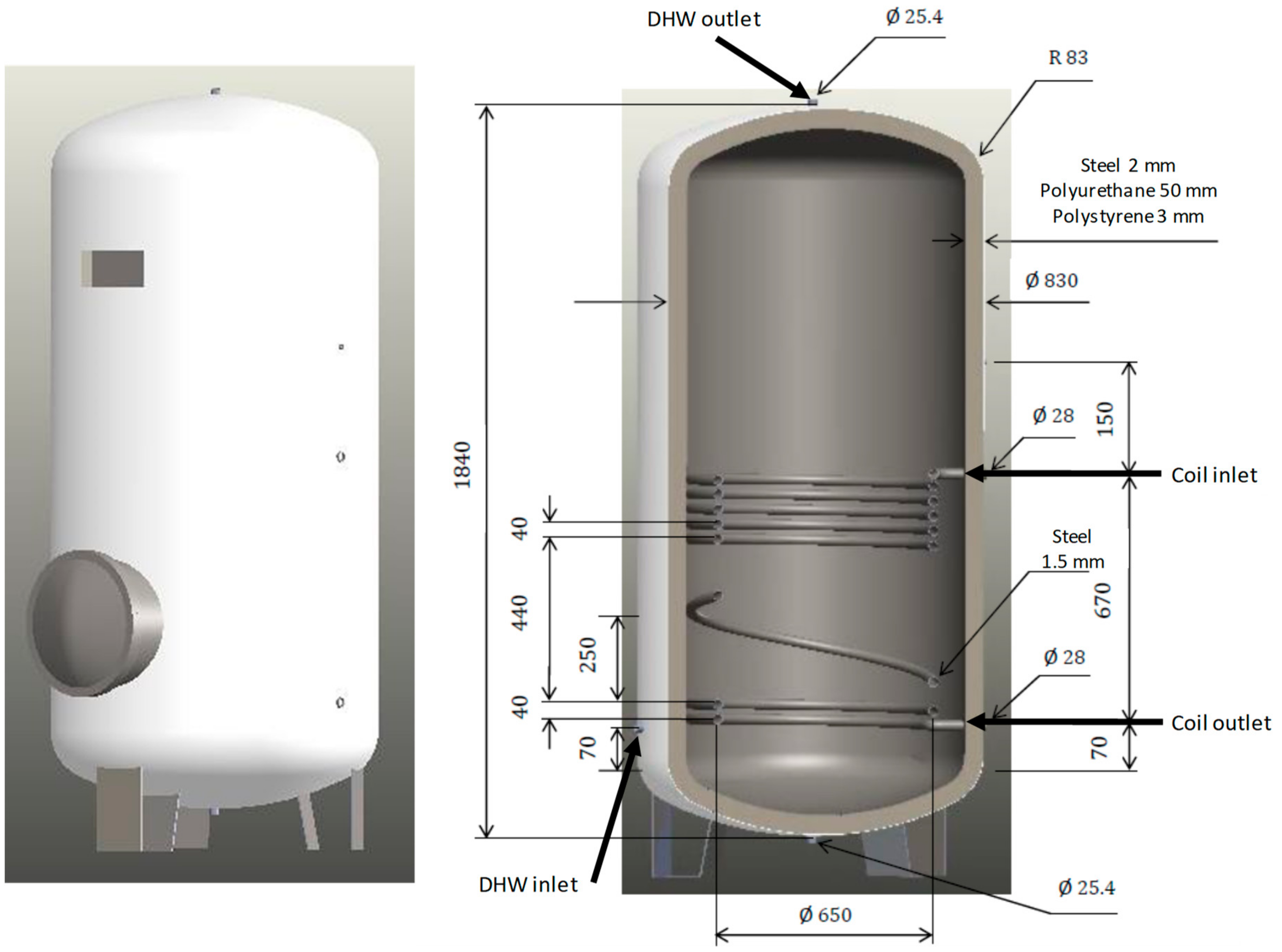
3. Studied Buffer Tank

The setup examined in this study is a buffer tank that provides DHW. The analysis is performed in steady and transient operating modes. The volume of the tank is approximately 1000 L. The inlet for the cold-water supply is side-mounted to the bottom of the tank, and the DHW exits from the top central section of the tank, which takes advantage of the natural convection of hot water that tends to flow up due to the temperature increase. The inlet of the hot water from the boiler is located at the middle of the tank on the side opposite to the cold-water supply inlet, and the outlet of the water that returns to the boiler is also on the opposite side of the cold-water inlet and at the same height. Therefore, the heat exchange has countercurrent water flows. Figure 1 shows two images of the tank, where one is an outside view, and the other is a cross-section with functional dimensions.

4. Buffer Tank Simulation

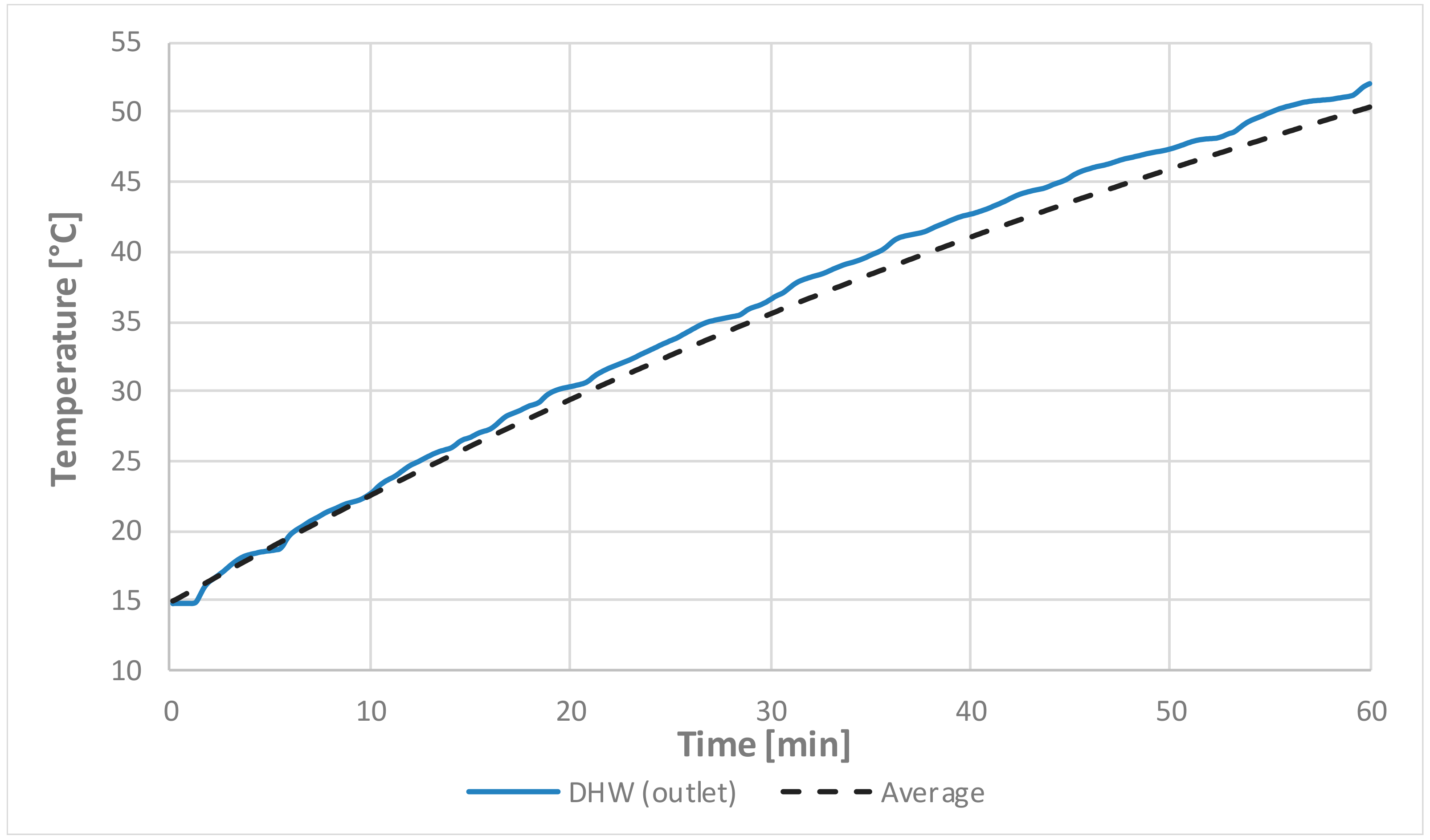
4.1. Simulation in Heat Exchanger Mode

First, a simulation of the tank producing hot water in continuous mode is performed; more specifically, the simulation is of the tank operating as a steady heat exchanger. The boundary conditions recommended by the manufacturer to consider the plant operating at full capacity are shown in Table 1.
Both parameters, mass flow and temperature of both flow circuits have an important influence of the overall system performance. The DHW mass flow is limited by the heat transferred from the coil to the tank interior. A higher mass flow rate of DHW means a lower outlet temperature in the steady operation for a constant heat transfer rate. Therefore, the demand for DHW is limited in time by the storage capacity of the tank and the heat transfer capacity. The heat transfer capacity is limited by the coil surface and the convective coefficients of the coil external surface, as long as the coil flow rate is enough to transport the energy from the boiler. The coil internal convection coefficients are higher than the external ones due to the turbulent internal flow whose velocity is usually higher than the external. The coil inlet temperature is also an important factor to determine the tank performance since a higher temperature difference boosts the heat transfer from the coil to the tank interior. In this case, both the high coil inlet temperature and flow rate make the heat transfer capacity of the flow a key factor in the system’s operation.
There are some uncertainties in the boundary conditions data. The temperature in the inlet of the coil can suffer soft oscillations around the target temperature when the boiler starts and stops its operating. The mass flow rate also suffers small variations around the target values. Both uncertainties are not considered in the simulations since they are usually slight variations and the time scales of the simulations performed in this work are significantly greater than the oscillations time scale. On the other hand, the tank inlet can also suffer slight variations in the temperature and the mass flow rate. Nevertheless, this water flux is only active when the tank works in continuous mode. As this is represented through steady simulations, the boundary conditions are modeled as the average values.
The same modeling is used for both fluids, DHW in the interior of the tank and water in the coil, except for the density. The density is modeled through the Boussinesq approximation for the DHW and through a polynomial function of temperature for the coil flow.
The heat exchanged between the water circuits can be visualized with the temperature field inside the entire tank and the temperature distribution. Figure 2 shows the temperature field in the center plane of the tank, and the graph shows the temperature at the centerline. There is noticeable stratification in the central area, where the temperature in the upper zone is greater than 40 °C, and in the lower zone, the stratification is close to that of the inlet supply water. The heat transfer is predominantly convective for the studied tank. On one hand, heat transfer calculations show that radiation is only 1–1.5% of the total heat transferred from the heat coil due to the high convective coefficients of water and the low temperatures (maximum 90 °C) of the system. On the other hand, conduction along the tank walls is virtually zero.
Table 2 shows the results of the most important parameters. The results show a DHW temperature of 41.1 °C. This is lower than the recommended temperature for DHW which is between 40–50 °C. This is caused by the ratio “heat exchanger area/tank volume”, that causes insufficient heat exchange. The coil return temperature is 75.2 °C, this means the boiler supplies a low amount of power since this temperature should be about 70 °C, which is recommended by the manufacturer.

4.2. Simulation in Accumulation Mode

This section simulates the process of heat accumulation. To achieve this, a transient simulation in which the inlet of DHW is shut off, is performed. A time step of 10-s is used to model the time increments, which helps to analyze the temperature evolution inside the tank. Several tests were performed to analyze the influence of mesh refinement. Figure 3 shows the results of the mesh convergence analysis. The average temperature of the buffer tank is compared for different meshes. No significant changes were observed for grids with elements smaller than 10 mm side. A mesh with more than 6 million elements was used. The elements have a characteristic length smaller than 10 mm and they are carefully refined in the proximities of the coil to ensure a high heat transfer accuracy in these zones.
The temperature evolution inside the tank is shown in Figure 4. The picture shows that the tank needs nearly an hour to reach a temperature of 50 °C. In Figure 5, the evolution of the temperatures in the outlet (DHW) and the average of the whole tank are compared. The DHW is slightly higher than the average, which means that the whole tank heats evenly and there is little stratification, as shown in Figure 4. This lack of stratification delays the availability of a desirable DHW temperature.

4.3. Aspects for Improvement
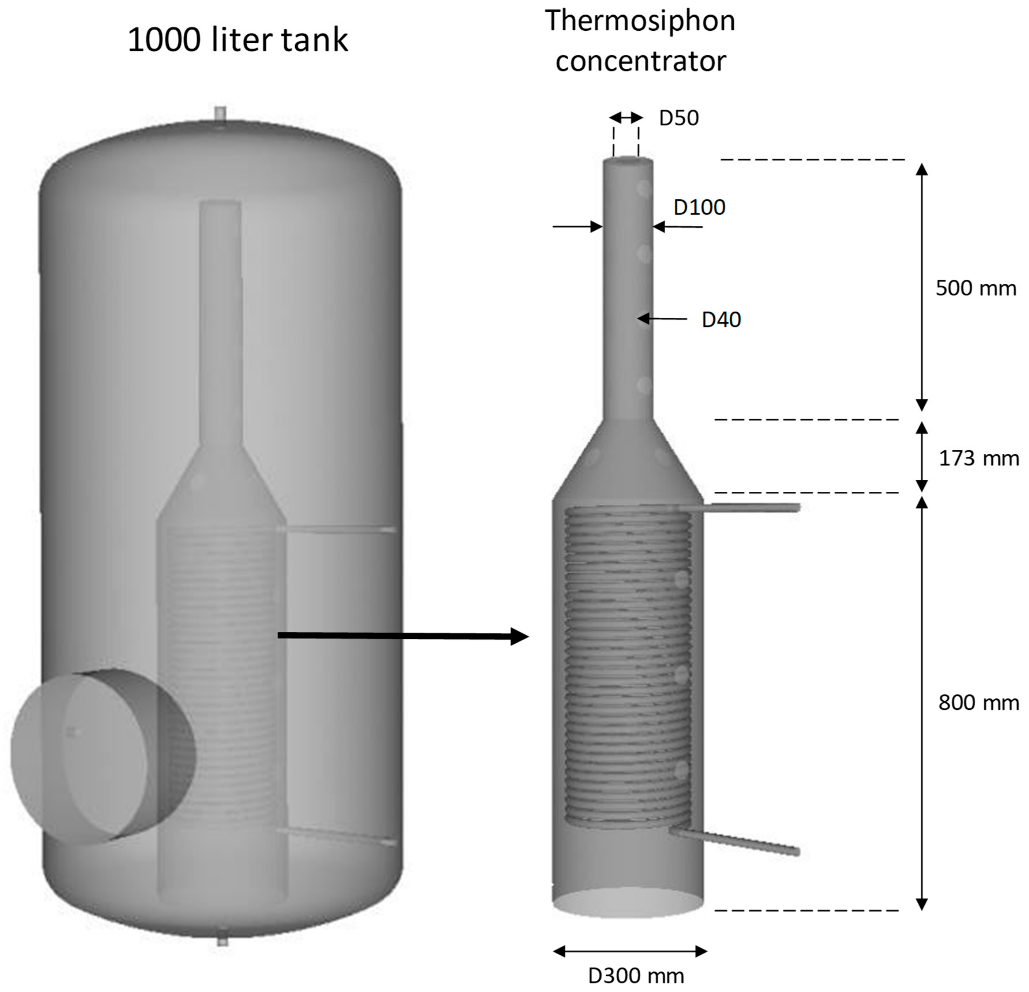
The simulation of the tank shows several aspects that are undesirable for proper operation. First, heating in the upper section is too slow, which is where the usable DHW water is located; approximately 45 min is required to heat the water to 45 °C. Another aspect is the low-temperature stratification, which causes extremely even heating throughout the tank and delays heating in the upper zone. The preference would be that the upper section heats up rapidly to a temperature between 45 and 60 °C and remains in that range while the lower layers heat up. Another aspect, although less relevant, is the difficulty of heating the bottom of the tank, which is below the coil. To improve these aspects, the following section proposes a redesign, and several cases are analyzed to obtain better performance, particularly in terms of better stratification and heating rate.

5. Improved Design

The results of the simulations indicated that a higher outlet DHW temperature is necessary; thus, a new design is proposed to increase thermal stratification in the tank. The flows and temperatures of the working fluids are the same as well as the surface area of the coil. Because having a system that minimizes the mixing of hot water that comes from the boiler with the cold supply water accumulated in the tank would avoid affecting stratification, the new design retains the coil that brings the heat-carrying fluid from the boiler, and a system with the cold-water inlet at the lowest height is added to ensure that stratification in the tank is affected as little as possible. The demanded DHW temperature must be reached as quickly as possible to meet any sudden demand. It is also important to have a "pocket" of hot water at an approximately constant temperature at the top of the tank to meet the DHW demand.
The authors’ previous paper [18] also proposed a new design to improve the thermal stratification of the buffer tank. In that case, an external devise was used to inject the hot water in the highest zone of the tank. In the present paper, a simpler and more efficient design is sought. To achieve the outlined objectives, it was decided to install a funnel-shaped tube inside the tank that encloses the heating coil and guides the hot water to the top section for greater temperature stratification and to ensure any sudden hot water demands can be met because the thermosyphon effect will be concentrated. The shape of the tube, which has a conical section in the middle that reduces the cross-section by two-thirds, seeks to improve the chimney or vacuum effect to make water flow upward more rapidly. In addition, there are several holes in the wall of the conical section of the tube, which can be opened or closed depending on the case, to mix the water that circulates inside with the rest of the accumulated water when their temperatures are similar following the natural thermosyphon mechanism. Figure 6 shows the geometry of the new design and the details of the tube that concentrates the thermosyphon effect.

6. Simulation of the Redesigned Tank

In this section, the obtained data are analyzed to assess the effectiveness of the redesign. The operation of the buffer tanks in both transient and stationary states is evaluated by analyzing various internal thermosyphon configurations obtained by opening or closing the perforations in the conical section and by extending the tube to improve heating at the bottom of the tank. Additionally, the values of the most important variables in those areas of interest are reported, including the outlet DHW temperature and the average temperature of the water accumulated in the tank. These values are then compared to the data of the previous simulations in both conditions to evaluate the efficiency of the new tank design.

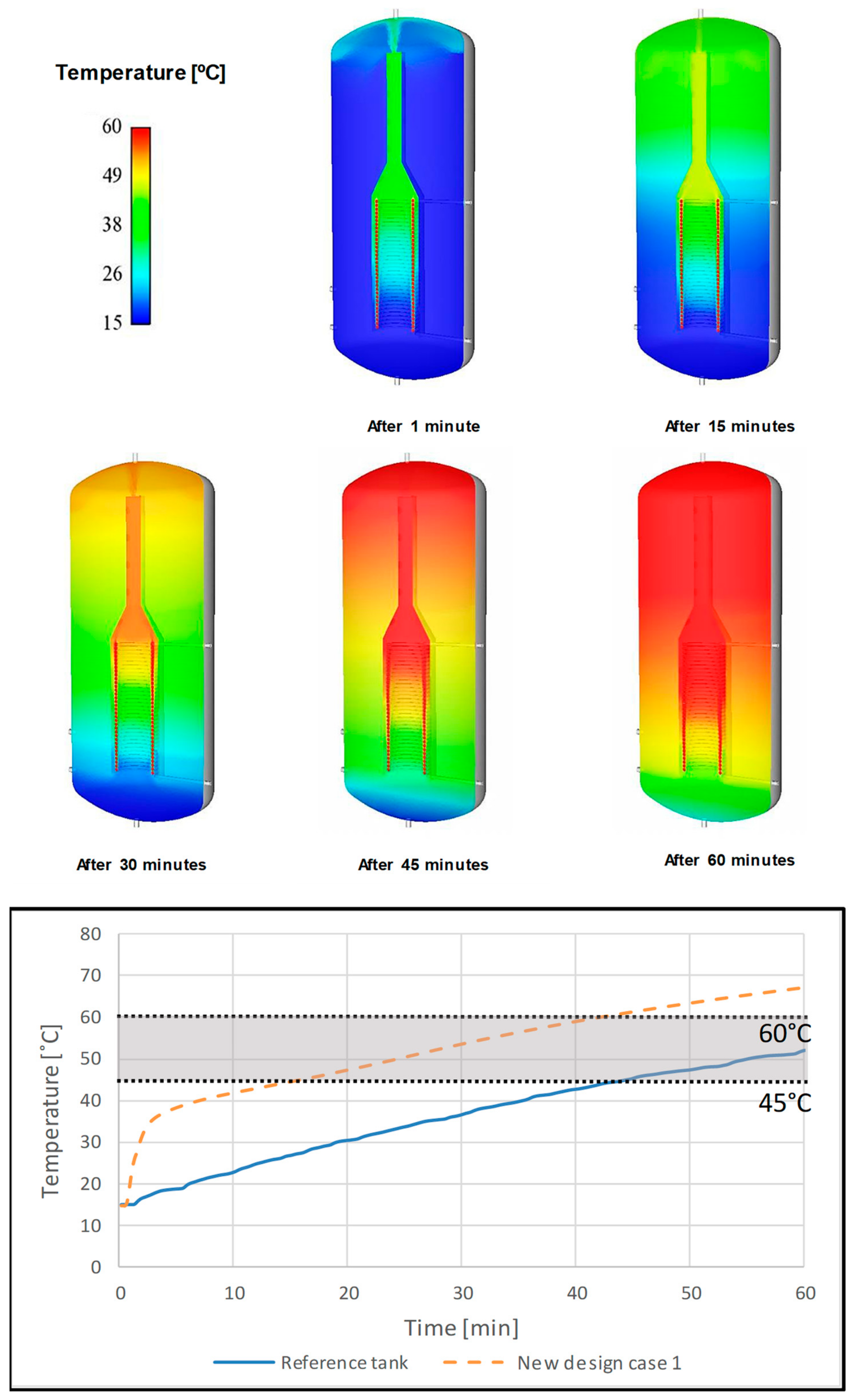
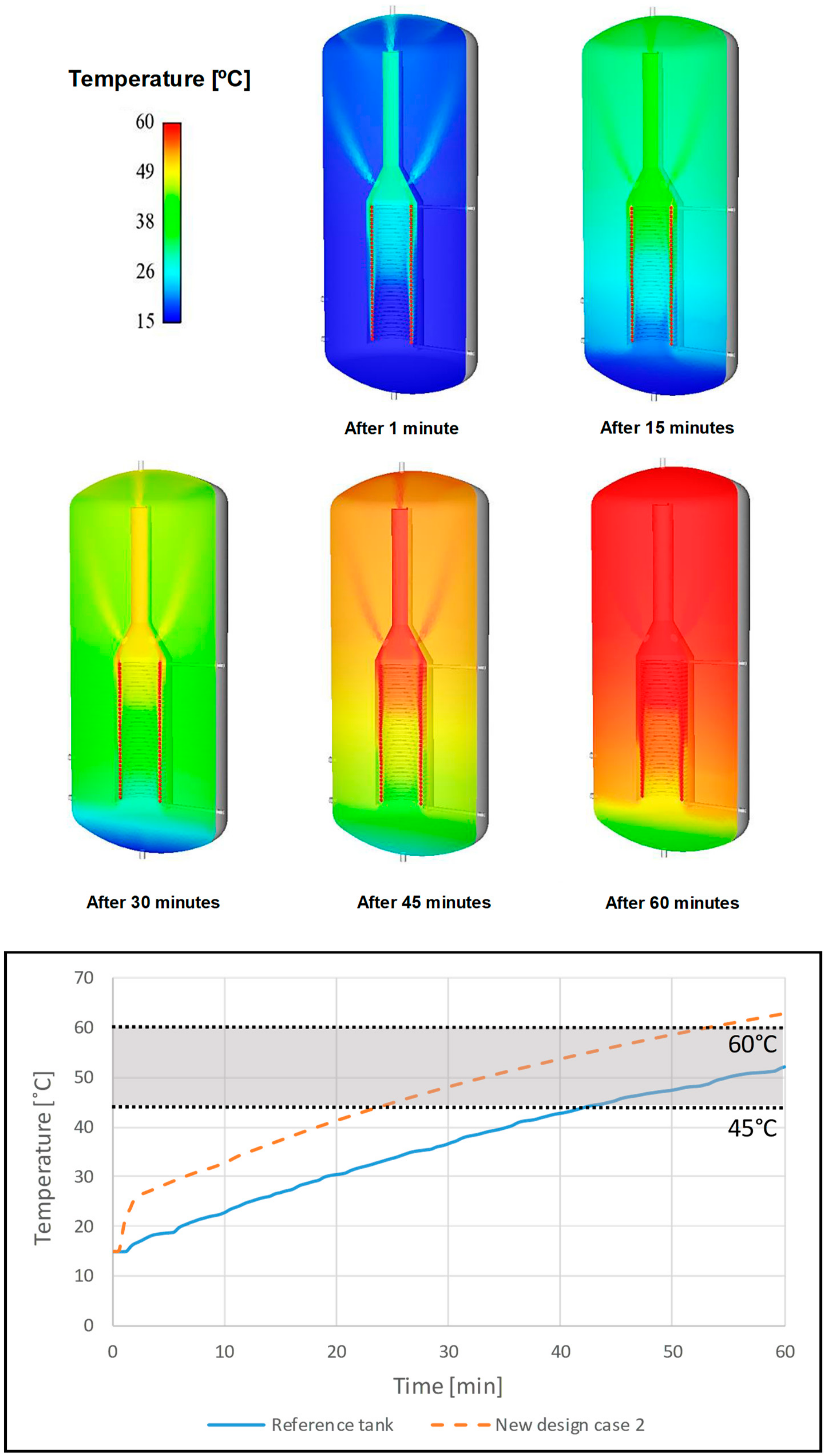
6.1. Study in Heating Mode

In this case, there is no demand for hot water from the tank, and therefore, all the energy that the boiler provides to the primary circuit is used to heat the water accumulated inside the tube and, simultaneously, the remaining water in the tank. This accumulation mode is studied with transient analyses, in which the variables of interest are the temperature and fluid velocity, and their evolutions over time are analyzed. Different simulations are conducted with the redesigned tank of the initial study. Each case involves a different operation inside the tank, where the goal is to determine which one meets the following outlined objectives: achieving 45 °C at the DHW outlet as rapidly as possible in the transient state, maintaining that output between 45 and 60 °C and ensuring hot water for consumption at 45 °C in the stationary state. The results of five simulations are shown below, and Table 3 shows the characteristics of the simulations.
Simulation 1:
First, the transient state of water accumulation is studied with all the side holes of the internal tube closed without any tube extension and with only the top outlet open. The case is configured to calculate 360 time steps with a variation of 10 s per step and to observe the operation of the new tank accumulating water for one hour. Figure 7 shows the temperature fields inside the tank and their evolutions over time.
Shortly after starting operation, the tank reaches a high temperature of approximately 40 °C in the upper third of the tank after 15 min, which indicates that the 45 °C setpoint will be reached rapidly. Another significant aspect of the temperature profiles is the stratification temperature achieved in the tank and how the 38 to 42 °C temperature front moves to the bottom as the tank water increases in temperature. Reaching the elevated temperature in such a short time in the upper section is due to the thermosyphon effect produced in the internal tube, which channels the water heated by the coil that it encloses to the top of the tank and makes it available for consumption. The graph shows a significant increase in temperatures between the two designs; it is remarkable in the redesign that the time required to reach a high DHW temperature at the top is considerably lower. The set point of 45 °C is reached in 16 min with the redesign, which is a significant improvement over the 45 min required by the reference tank with the initial geometry. The outlet DHW temperature varies 16 °C on average between the redesign and the reference tank, and the temperature in the redesign is always considerably higher. At the end of the 60-min simulation, the temperature is 67 °C, which exceeds the range of 45 to 60 °C established as the DHW reference. It is unsafe to exceed 60 °C for hot water intended for consumption because it may burn users; therefore, this case involves a new redesign of the function of the thermosyphon tube holes.
Simulation 2:
In this transient state case, the holes in the conical section and the top outlet are open from the beginning without any tube extension. The goal is to determine whether it is possible to reduce the outlet DHW temperature by reducing the flow to the upper section at the start of operation and with the upper hole open to rapidly reach 45 °C at the outlet. Figure 8 analyzes the temperature fields inside the tank and its evolution over time. Clearly, the temperature of the stored water is lower both inside and outside the internal tube. Additionally, the temperature stratification is maintained; however, the temperature front that moves toward the lower section becomes more diffuse. The temperature of 45 °C is reached in 25 min of operation, which contrasts with the 15 min of simulation 1, and 45 min of the tank with the initial geometry. In this aspect, the response of the tank is lower because the time to reach the reference temperature at the outlet increases.
Simulation 3:
In this transient state case, all the side holes of the internal tube are closed, there are no tube extensions, and only the top outlet is open as in the previous case but only for a half hour of operation. After 30 min, the four holes in the conical section are opened until reaching one hour of operation in accumulation mode. Figure 9 analyzes the temperature fields inside the tank and the evolution over time. As time progresses, the 38–42 °C temperature front moves toward the bottom section as the average temperature of the tank increases. Temperature stratification exists in well-defined layers inside the internal tube, which is also transmitted to the rest of the accumulated water. The graph shows that the evolution of the outlet DHW temperature contrasts with the initial case. In this case, it takes 15 min of operation to reach 45 °C vs. the 45 min required in the tank with the initial geometry. It is noted that after 30 min, the outlet DHW temperature stops increasing and stays at 53 °C until minute 36. From that moment, the temperature begins to increase again until it reaches 63 °C after 60 min of operation. This shows that the DHW temperature remains within the desired range for a longer time, which demonstrates the benefit of opening the holes of the conical section after being closed at the beginning.
Simulation 4:
In this transient state case only, the top outlet is open during the first half hour, and during the subsequent half hour, it is closed; then, the four holes of the conical section are opened. The goal here is to achieve the 45 °C set point at the DHW outlet rapidly by opening the top outlet at the start of operation while maintaining a temperature within the 45–60 °C range in that section but without exceeding 60 °C. After the outlet is closed, the holes of the conical section are opened after 30 min of operation. Thus, the heating of the tank continues with the internal thermosyphon system; however, water is released to the lower level in the tank to prevent an excessive increase in the DHW temperature. Figure 10 shows the temperature fields inside the tank and the evolution over time. A large temperature stratification is observed in the internal thermosyphon system, which is also transmitted to the rest of the accumulated water. In addition, the 38 to 42 °C temperature front moves forward as a higher temperature in the tank is reached. In the first minute, an elevated temperature is already reached at the DHW outlet area, and the 45 °C set point temperature is achieved after approximately 15 min. Just as in cases 1 and 3, the time required to reach the 45 °C set point is 15 min. In this case, the outlet DHW temperature stabilizes at approximately 53 °C after 30 to 44 min. The temperature remains within the 45–60 °C range until heating is finished and does not go above 60 °C, which prevents user burns. This is the best case to meet the requirements because it provides a rapid response to a sudden DHW demand and stays within the temperature range specified to meet the operational safety requirements.
Simulation 5:
In this operation case, the sequence to open the holes in simulation 4 is used, and the impact of extending the internal tube to achieve a higher temperature at the bottom of the tank is analyzed. Therefore, the top outlet is open during the first half hour and then closed, and the four holes of the conical section are then opened with the extension of the thermosyphon tube. Figure 11 shows the evolution of the outlet DHW temperatures and the temperature fields inside the tank. The internal tube area in contact with the wall extension initially creates an area of lower temperature due to the cold water entering from outside the tube, which has not been heated by the coil. However, as time progresses, the effect is that the lower area of the tank reaches a temperature of approximately 38 °C after 45 min of operation. Therefore, a higher temperature at the bottom of the tank is achieved to obtain a greater uniformity of temperatures in the coil area. Thus, heat transmission is more efficient.
Figure 12 shows a comparison of the outlet DHW temperatures, average temperatures and heat transfer after analyzing the different graphs and profiles of the operation cases of the redesigned tank; the cases that more effectively meet the optimal objectives are cases 4 and 5. Regarding the average temperatures, the redesign improved the average temperature of the tank in all cases with no significant differences, which indicates a heat transfer improvement due to the concentrated thermosyphon effect. Although, in case 5, the achieved outlet DHW temperature and the heat exchanged are slightly lower in comparison with those of case 4, it is confirmed that the extension of the internal thermosyphon tube enables the accumulation of hotter water in the bottom of the tank. It is therefore important to consider both cases in a stationary state due to the similarity of results. The heat transfer graph shows a clear improvement of the redesign effectiveness, which is higher than the reference case for all scenarios, especially for the “case 2” (tube perforations opened). This shows that the thermosyphon effect is the main mechanism in the heat transfer increase, since the “case 2” produces a higher buoyancy flow. This scenario (case 2) is the most efficient in an energy analysis, however, regarding the DHW heating times, other cases with a higher stratification degree produce better results. Therefore, both effects, the thermosyphon effect and stratification degree, should be considered by manufacturers for the buffer tanks design specifications.

6.2. Study of Heat Exchanger Mode

After analyzing the operation of the redesigned tank during a stationary heating test, the operation during the consumption of DHW is analyzed; therefore, a simulation in the stationary state is performed. Two cases of the redesigned tank are studied, i.e., with and without extension of the inner tube. In both cases, only the top outlet remains open. Figure 13 shows the temperature fields inside the reference tank and of the tanks with the internal thermosyphon tube. In both redesigns, the temperature of the water accumulated in the upper section is higher than that in the tank with the initial geometry in stationary mode. In addition, there is a considerably higher temperature stratification, which benefits the heat exchange; this is because the thermosyphon effect increases the speed of the fluid flowing up, and thus, the convective heat transfer is greater. The stratification is slightly more defined in the case of the redesign with the tube extension because it collects water from the bottom of the tank, which is the coldest point. Table 4 presents the numerical values of the outlet DHW temperature, which is higher in the redesign cases. The improvement in the heat exchange mentioned above can also be observed.

7. Conclusions

This theoretical study analyzes the operation of a buffer tank using Computational fluid dynamics (CFD) techniques and proposes a design to improve the thermal behavior and the stratification performance of the reference tank. The proposed model was shown to be an efficient tool to the study of different design alternatives since it allows us to analyze thermal performance without excessive computational costs.
The operation of the initial tank is simulated in continuous domestic hot water (DHW) consumption mode and in accumulation mode for one hour. This simulation shows that it heats up evenly, and the temperature stratification is low, which implies a long heating time to reach DHW use temperatures. To alleviate this problem, a redesign of the geometry is proposed in which the heating coil is introduced into an inner tube, and thus, the thermosyphon effect is concentrated to increase natural convection. Therefore, the tube supplies hot water at the top of the tank, and thermal stratification is improved.
The simulation of the redesign in different situations shows a noticeable improvement in the stratification and heating times. The time to reach the set point temperature of 45 °C is reduced from 44 to 15 min, and the thermal stratification is greatly improved. In addition, by opening or closing the different outlets of the inner tube, it is possible to regulate the heating of DHW to prevent dangerous overheating during the use of DHW.

Author Contributions

M.A.G.: models development, simulation and manuscript write up. S.C.: simulation and results post processing. J.C.: simulation and article supervision. J.L.M.: project organization.

Funding

This research received no external funding.

Conflicts of Interest

The authors declare no conflict of interest.

References

  1. Fan, J.; Furbo, S. Thermal stratification in a hot water tank established by heat loss from the tank. Sol. Energy 2012, 86, 3460–3469. [Google Scholar] [CrossRef]
  2. Han, Y.M.; Wang, R.Z.; Dai, Y.J. Thermal stratification within the water tank. Renew. Sustain. Energy Rev. 2009, 13, 1014–1026. [Google Scholar] [CrossRef]
  3. Andersen, E.; Furbo, S. Theoretical comparison of solar water/space-heating combi systems and stratification design options. J. Sol. Energy Eng. Trans. Asme. 2007, 129, 438–448. [Google Scholar] [CrossRef]
  4. Ievers, S.; Lin, W. Numerical simulation of three-dimensional flow dynamics in a hot water storage tank. Appl. Energy 2009, 86, 2604–2614. [Google Scholar] [CrossRef] [Green Version]
  5. Kang, M. Thermal mixing in a water tank during heating process. Int. J. Heat Mass Transf. 2002, 45, 4361–4366. [Google Scholar] [CrossRef]
  6. Dragsted, J.; Furbo, S.; Dannemand, M.; Bava, F. Thermal stratification built up in hot water tank with different inlet stratifiers. Sol. Energy 2017, 147, 414–425. [Google Scholar] [CrossRef] [Green Version]
  7. Bouhal, T.; Fertahi, S.; Agrouaz, Y.; El Rhafiki, T.; Kousksou, T.; Jamil, A. Numerical modeling and optimization of thermal stratification in solar hot water storage tanks for domestic applications: CFD study. Sol. Energy 2017, 157, 441–455. [Google Scholar] [CrossRef]
  8. Abdelhak, O.; Mhiri, H.; Bournot, P. CFD analysis of thermal stratification in domestic hot water storage tank during dynamic mode. Build. Simul. 2015, 8, 421–429. [Google Scholar] [CrossRef]
  9. Arslan, M.; Igci, A.A. Thermal performance of a vertical solar hot water storage tank with a mantle heat exchanger depending on the discharging operation parameters. Sol. Energy 2015, 116, 184–204. [Google Scholar] [CrossRef]
  10. Fan, J.; Ptacek, V.; Furbo, S.; Dragsted, J.; Sun, P. Performance analysis of a new thermal stratification device for hot water storage tank heated at the bottom. In Proceedings of the ISES Solar World Congress 2015, Daegu, Korea, 8–12 November 2015. [Google Scholar]
  11. Wang, Z.; Zhang, H.; Dou, B.; Huang, H.; Wu, W.; Wang, Z. Experimental and numerical research of thermal stratification with a novel inlet in a dynamic hot water storage tank. Renew. Energy 2017, 111, 353–371. [Google Scholar] [CrossRef]
  12. Gómez, M.A.; Collazo, J.; Porteiro, J.; Míguez, J.L. Numerical study of the thermal behaviour of a water heater tank with a corrugated coil. Int. J. Heat Mass Transf. 2018, 122, 574–586. [Google Scholar] [CrossRef]
  13. Patankar, S.V. Numerical Heat Transfer and Fluid Flow; Hemisphere Publishing Corporation: New York, NY, USA, 1980; pp. 126–131. [Google Scholar]
  14. Kassemi, M.; Kartuzova, O. Effect of interfacial turbulence and accommodation coefficient on CFD predictions of pressurization and pressure control in cryogenic storage tank. Cryogenics 2016, 74, 138–153. [Google Scholar] [CrossRef] [Green Version]
  15. Sivalingam, K.; Martin, S.; Wala, A.A.S. Numerical Validation of Floating OffshoreWind Turbine Scaled Rotors for Surge Motion. Energies 2018, 11, 2578. [Google Scholar] [CrossRef]
  16. Versteeg, H.K.; Malalasekera, W. An Introduction to Computational Fluid Dynamics. Available online: http://ftp.demec.ufpr.br/disciplinas/TM702/Versteeg_Malalasekera_2ed.pdf (accessed on 5 June 2019).
  17. Gray, D.D.; Giorgini, A. The validity of the boussinesq approximation for liquids and gases. Int. J. Heat Mass Transf. 1976, 19, 545–551. [Google Scholar] [CrossRef]
  18. Gómez, M.A.; Collazo, J.; Porteiro, J.; Míguez, J.L. Numerical study of an external device for the improvement of the thermal stratification in hot water storage tanks. Appl. Therm. Eng. 2018, 144, 996–1009. [Google Scholar] [CrossRef]
Figure 1. Geometry of the buffer tank [18].
Energies 12 02162 g001
Figure 2. Temperature field in the tank.
Energies 12 02162 g002
Figure 3. Temperature evolution of the tank for different mesh refinements (size of element side).
Energies 12 02162 g003
Figure 4. Temperature evolution in the middle plane of the tank [18].
Energies 12 02162 g004
Figure 5. DHW outlet and tank average temperatures during the tank heating process.
Energies 12 02162 g005
Figure 6. Buffer tank redesign.
Energies 12 02162 g006
Figure 7. Evolution of the temperature field in simulation 1 and comparison of the DHW temperatures with the reference case (average temperature at the DHW outlet).
Energies 12 02162 g007
Figure 8. Evolution of the temperature field in simulation 2 and comparison of DHW temperatures with the reference case (average temperature at the DHW outlet).
Energies 12 02162 g008
Figure 9. Evolution of the temperature field in simulation 3 and comparison of DHW temperatures with the reference case (average temperature at the DHW outlet).
Energies 12 02162 g009
Figure 10. Evolution of the temperature field in simulation 4 and comparison of DHW temperatures with the reference case (average temperature at the DHW outlet).
Energies 12 02162 g010
Figure 11. Evolution of the temperature field in simulation 5 and comparison of DHW temperatures with the reference case (average temperature at the DHW outlet).
Energies 12 02162 g011
Figure 12. Comparison of outlet DHW temperatures, average temperatures and heat exchanged in the entire tank.
Energies 12 02162 g012
Figure 13. Comparison of the temperature fields inside the reference tank and the redesigned tanks.
Energies 12 02162 g013
Table 1. Boundary conditions of the simulation in continuous mode.
MagnitudeValue
DHW mass flux [l/s]0.418
Inlet water temperature [°C]15
Coil mass flux [l/s]0.76
Coil inlet temperature [°C]90
Table 2. Results of the steady simulation of continuous water heating.
MagnitudeValue
DHW temperature [°C]41.1
Coil return temperature [°C]75.2
Coil heat exchanged [kW]45.8
Heat exchange surface area [m²]1.45
Table 3. Characteristics of transient simulations in heating mode.
TestMain Characteristics
Simulation 1The tube perforations remain closed for 60 min of heating.
Simulation 2The tube perforations are open for 60 min of heating.
Simulation 3The tube perforations remain closed for 30 min and are then opened with continued heating for 30 additional minutes.
Simulation 4The tube perforations remain closed for 30 min and are then opened; the top outlet of the tube is closed for the next 30 min.
Simulation 5The tube is extended at the bottom, and the simulation is performed under the same conditions of those of simulation 4.
Table 4. Comparison of the results of the continuous consumption simulation in the reference tank and the redesigned tanks.
MagnitudeReference TankRedesign without ExtensionRedesign with Extension
DHW temperature [°C]41.045.746.2
Coil return temperature [°C]75.272.672.4
Coil heat exchanged [kW]45.853.854.6
Heat exchange surface area [m²]1.451.451.45

