Optimal Configuration of Electric-Gas-Thermal Multi-Energy Storage System for Regional Integrated Energy System


Abstract
:1. Introduction
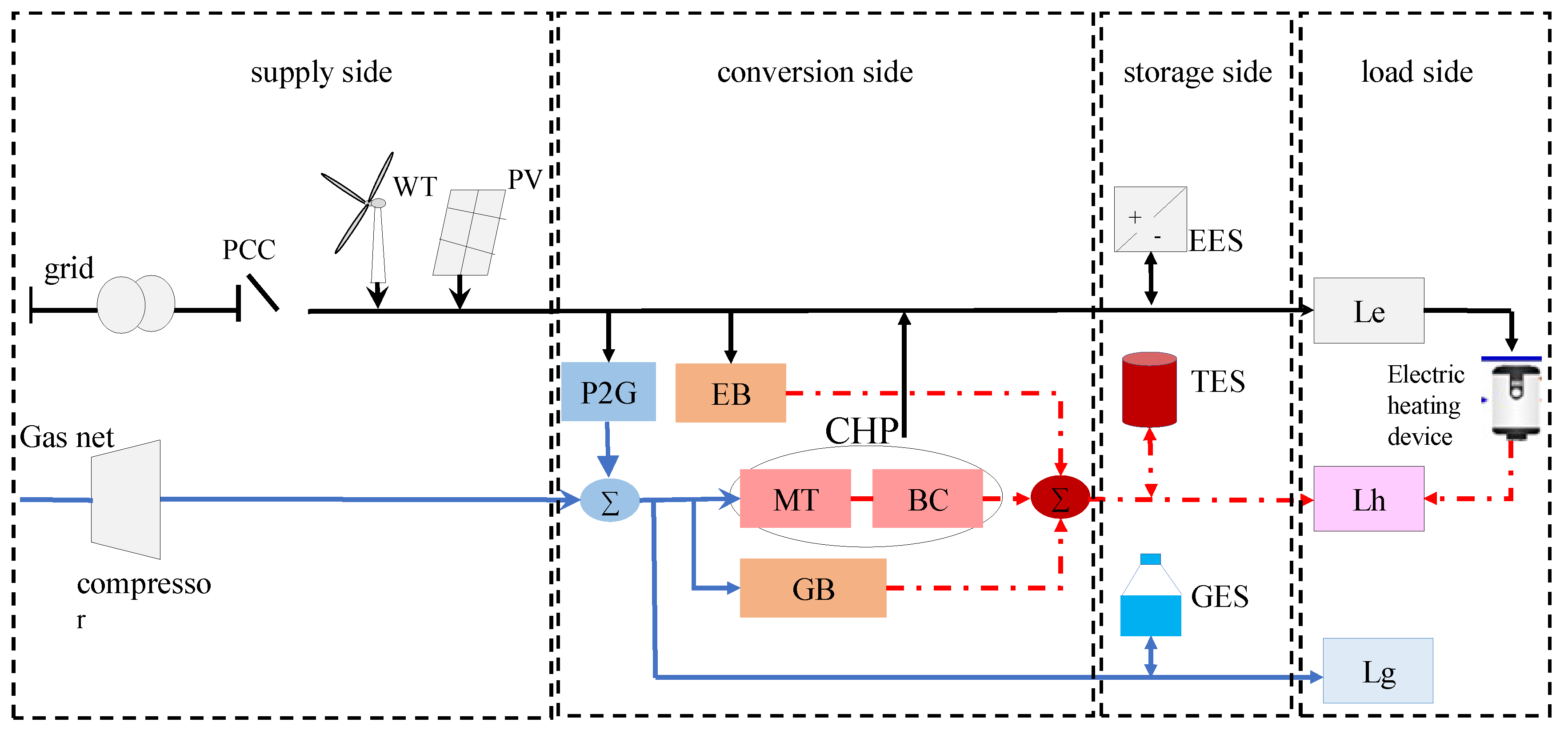
2. The RIES Mathematical Model
2.1. Load Model
2.2. Supply Model
2.3. Storage Model
2.4. Conversion Model
3. The Configuration Optimization Model of Energy Storage Systems
3.1. The Objective Function
3.2. The Constraints
3.2.1. Power Balance Constraint
3.2.2. Interactive Power Constraint
3.2.3. Controllable Unit Constraint
3.2.4. Energy Storage System Constraint
3.2.5. Abandoned Wind and Photovoltaic Power Constraint
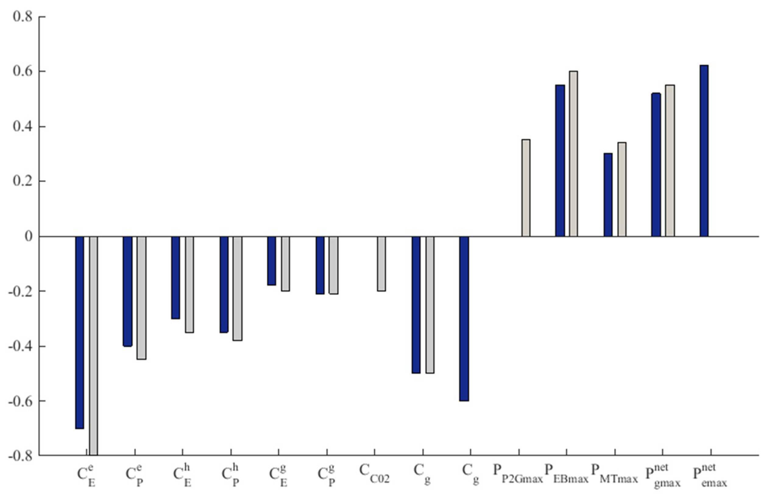
3.3. The Sensitivity Analysis
4. Case Study
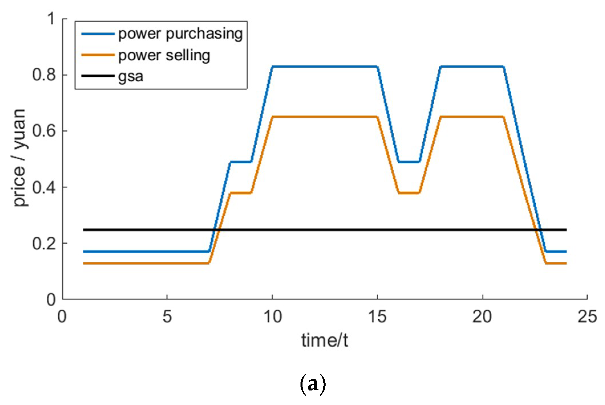
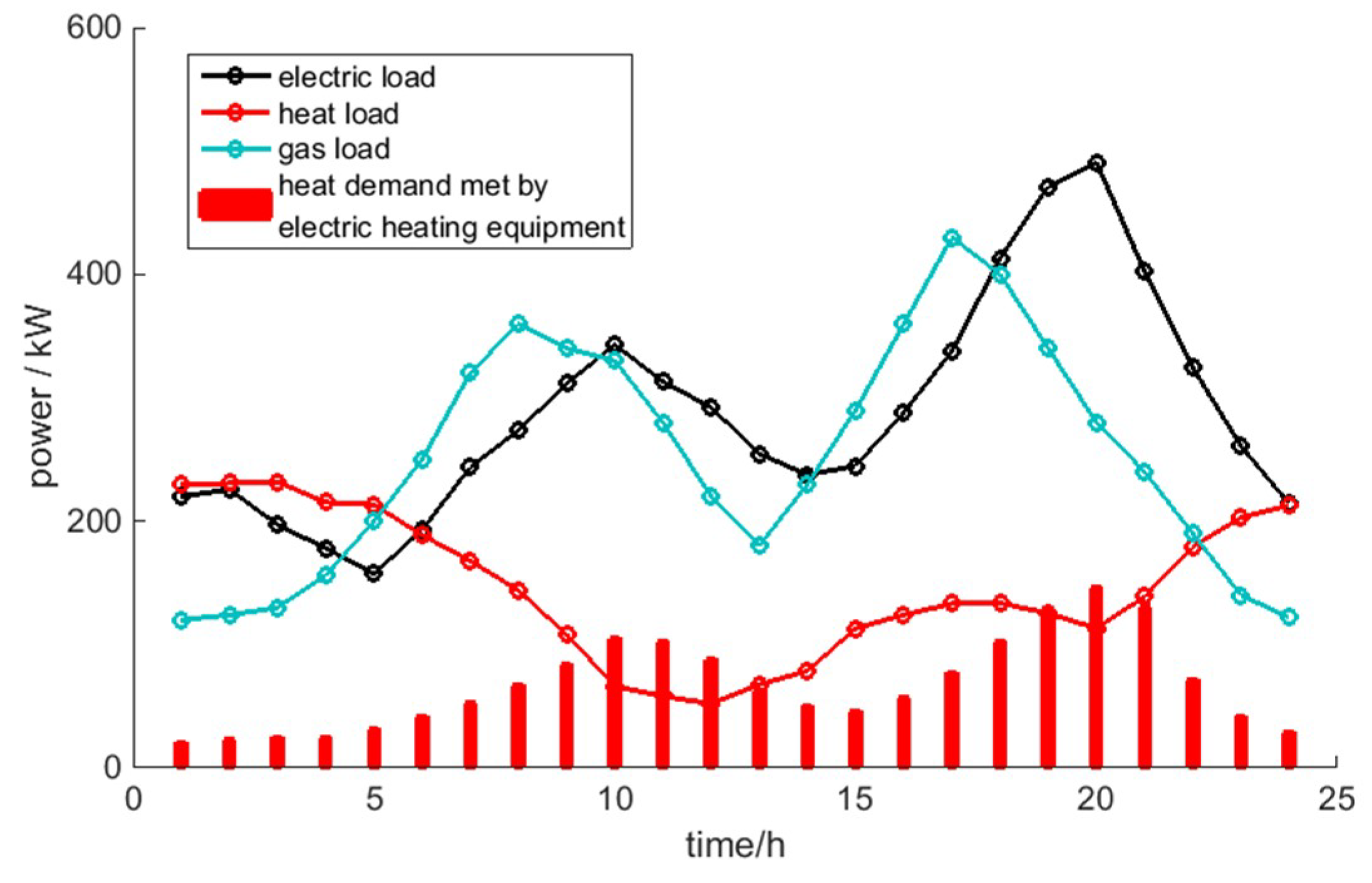
4.1. Basic Data
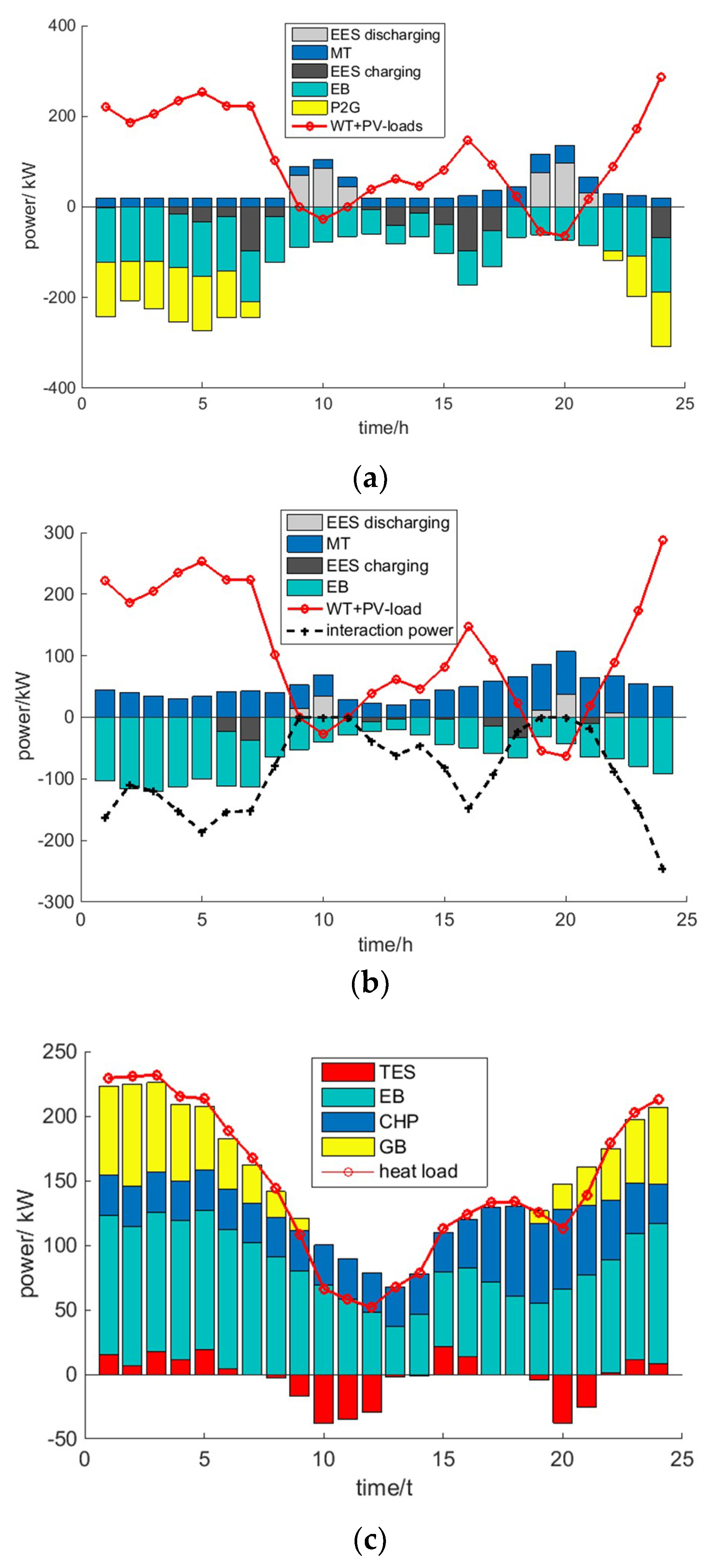
4.2. Results and Analysis
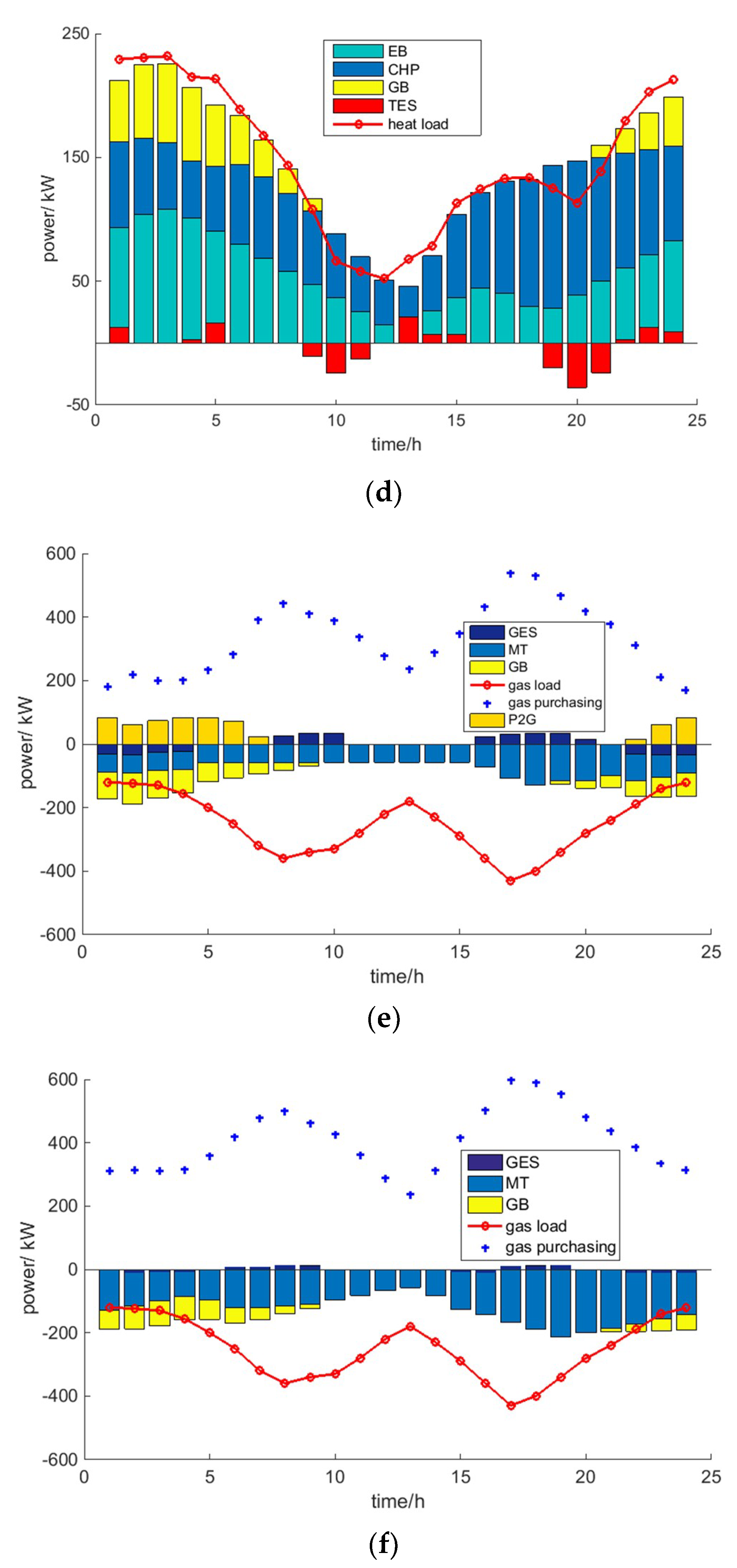
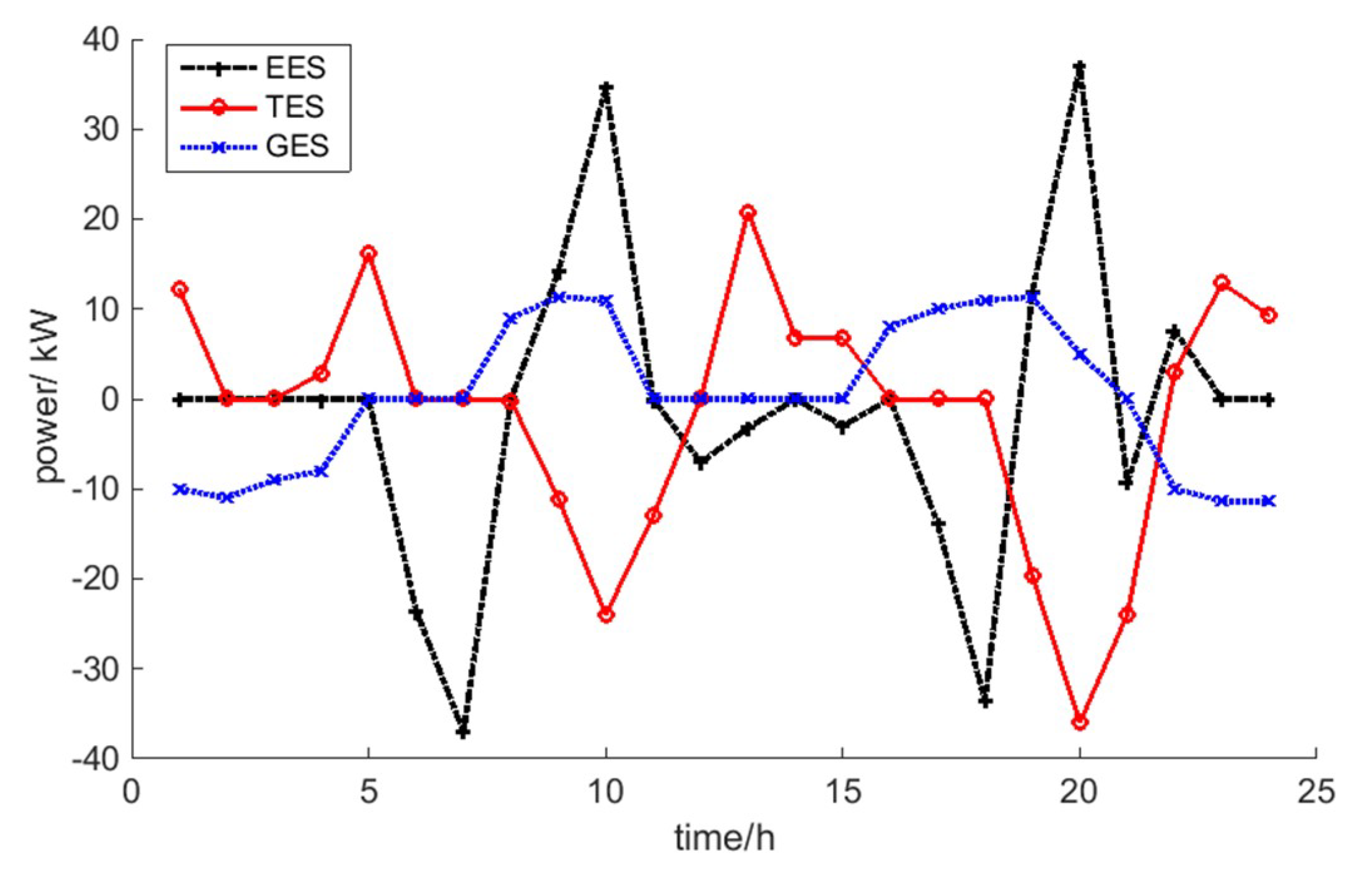
4.2.1. Impact of Energy Storage Equipment and Electric Energy Substitution on RIES
4.2.2. Economic Analysis in Different Energy Storage Modes
4.3. Sensitivity Analysis
5. Discussion
6. Conclusions
Author Contributions
Funding
Conflicts of Interest
Nomenclature
| Acronyms | |
| RIES | Regional integrated energy system |
| MILP | Mixed integer linear problems |
| CHP | Combined heat and power |
| HP | Electric heat pump |
| EB | Electric boiler |
| P2G | Power to gas |
| PV | Photovoltaic |
| WT | Wind turbine |
| MT | Micro turbine |
| BC | Bromine cooler |
| GB | Gas boiler |
| EES | Electrical energy storage |
| TES | Thermal energy storage |
| GES | Gas energy storage |
| Symbols and matrix | |
| e, h, g | Electric, heat, gas, respectively |
| n, N | User, number of users, respectively |
| u | 0-1 variable which indicates the operating mode of RIES |
| i | Type of energy storage system |
| y, s, l | Source, storage and load, respectively |
| L, C | Load matrix, energy conversion matrix, respectively |
| P, S | Energy supply matrix, energy storage matrix, respectively |
| , | Equivalent load matrix, interactive power matrix, respectively |
| P2G and EB power matrix | |
| Wind and photovoltaic power matrix | |
| , | Charging matrix, discharging matrix, respectively |
| X | Parameter matrix |
| Variables | |
| t | Time |
| T | Total number of daily scheduling periods |
| Δt | Unit scheduling time |
| , | Aggregate electric load of users, electric load of user n at time t, respectively |
| , | Aggregate heat load of users, heat load of user n at time t, respectively |
| , | Aggregate gas load of users, gas load of user n at time t, respectively |
| E(t) | Direct electric demand |
| H(t) | Direct heat demand |
| G(t) | Direct gas demand |
| , | Electric, heat demand of user n produced from electric heating supply |
| , | Equivalent electric load, equivalent heat load at time t, respectively |
| Equivalent gas load at time t | |
| , | P2G power, EB power at time t, respectively |
| , | P2G efficiency, EB efficiency, respectively |
| Wind turbine output power at time t | |
| Photovoltaic output power at time t | |
| Rated wind output power without abandoning wind power at time t | |
| Rated photovoltaic power without abandoning photovoltaic power at time t | |
| βWT, βPV | Wind and photovoltaic power utilization rate, respectively |
| Abandoned power at time t | |
| , | Input electric power, gas power at time t, respectively |
| Interactive power between the RIES and the external power grid at time t | |
| Interactive power between the RIES and natural gas network at time t | |
| Storage capacity of EES at time t | |
| Storage capacity of TES at time t | |
| Storage capacity of GES at time t | |
| , , | Self-discharge rate, self-heat dissipation rate and self-deflating rate, respectively |
| , | Charging and discharging power of EES at time t |
| , | Charging and discharging efficiency of EES |
| , | Charging and discharging power of TES at time t |
| , | Charging and discharging efficiency of TES |
| , | Charging and discharging power of GES at time t |
| , | Charging and discharging efficiency of GES |
| , | Power of EES and TES at time t |
| Power of GES at time t | |
| λ1(t), λ2(t), λ3(t) | Distribution coefficient that the input gas power is assigned to MT, GB and gas loads, respectively |
| , | Efficiency and heat loss rate of MT |
| , | Heating coefficient and smoke recovery rate of BC |
| Efficiency of GB | |
| Daily average allocation cost over the life cycle | |
| Purchase cost including interaction cost, material costs | |
| Start-stop cost | |
| Maintenance cost | |
| Abandonment cost | |
| , | Electricity and natural gas prices, respectively |
| ε | CO2 coefficient required to generate unit natural gas |
| CO2 price | |
| , | EB, MT start-up costs, respectively |
| GB start-up costs | |
| UEB(t), UMT(t) | EB, MT start and stop status at time t respectively |
| UGB(t) | GB start and stop status at time t |
| , | Unit power maintenance cost of MT, PV, respectively |
| , | Unit power maintenance cost of WT, GB, respectively |
| , | Unit power maintenance cost of EB, P2G, respectively |
| Unit power maintenance cost of energy storage systems | |
| Unit abandonment cost of PV and WT | |
| Output power of MT | |
| Output power of GB | |
| , | Upper and lower limits of the interaction power between the RIES and the distribution network |
| , | Upper and lower limits of the interaction power between the RIES and the natural gas network |
| Upper limits of MT power | |
| Upper limits of GB power | |
| Upper limits of EB power | |
| Upper limits of P2G power | |
| Lower limits of MT power | |
| Lower limits of GB power | |
| Lower limits of EB power | |
| Lower limits of P2G power | |
| Up climbing rate of the MT | |
| Up climbing rate of the GB | |
| Up climbing rate of the EB | |
| Down climbing rate of the MT | |
| Down climbing rate of the GB | |
| Down climbing rate of the EB | |
| , | Upper and lower limits of energy storage installation capacity |
| , | Upper and lower limits of energy storage installation power |
| , | Upper and lower limits of the electric storage equipment remaining energy |
| , | Upper and lower limits of the thermal storage equipment remaining energy |
| , | Upper and lower limits of the gas storage equipment remaining energy |
| , , | Rated capacity of EES, TES and GES, respectively. |
| , | Rated capacity and rated power of electric, heat and gas energy storage equipment |
| Lower limits of charging and discharging power | |
| 0-1 variable that represents the operative mode of storage equipment at time t | |
| Lowest abandonment rate that can be accepted by the RIES | |
| Parameter i in X | |
| Sensitivity of the objective function f to | |
References
- Stephen, C.; Pierluigi, M. Integrated Electrical and Gas Network Flexibility Assessment in Low-Carbon Multi-Energy Systems. IEEE Trans. Sustain Energy 2015, 7, 718–731. [Google Scholar] [CrossRef]
- Mancarella, P. Smart Multi-Energy Grids: Concepts, benefits and challenges. In Proceedings of the 2012 IEEE Power and Energy Society General Meeting, San Diego, CA, USA, 22–26 July 2012. [Google Scholar]
- Tang, B.; Gao, G.; Xia, X.; Yang, X. Integrated Energy System Configuration Optimization for Multi-Zone Heat-Supply Network Interaction. Energies 2018, 11, 3052. [Google Scholar] [CrossRef]
- Wang, Y.; Wang, Y.; Huang, Y.; Yu, H.; Du, R.; Zhang, F.; Zhang, F.; Zhu, J. Optimal scheduling of the regional integrated energy system based on energy price demand response. IEEE Trans. Sustain. Energy 2018, 99, 1. [Google Scholar] [CrossRef]
- Yilmaz, H.U.; Keles, D.; Chiodi, A.; Hartel, R.; Mikulic´, M. Analysis of the power-to-heat potential in the European energy system. Energy Strategy Rev. 2018, 20, 6–19. [Google Scholar] [CrossRef]
- Lund, H.; Werner, S.; Wiltshire, R.; Svendsen, S.; Thorsen, J.E.; Hvelplund, F.; Mathiesen, B.V. 4th generation district heating (4gdh): integrating smart thermal grids into future sustainable energy systems. Energy 2014, 68, 1–11. [Google Scholar] [CrossRef]
- Chen, J.; Wu, W.; Zhang, B.; Sun, Y. A Rolling Generation Dispatch Strategy for Co-generation Units Accommodating Large-scale Wind Power Integration. Autom. Electr. Power Syst. 2012, 36, 21–27. [Google Scholar]
- Lyu, Q.; Jiang, H.; Chen, T.; Wang, H.; LYU, Y.; Li, W. Wind Power Accommodation by Combined Heat and Power Plant with Electric Boiler and Its National Economic Evaluation. Autom. Electr. Power Syst. 2014, 38, 6–12. [Google Scholar] [CrossRef]
- Tan, Z.; Tan, Q.; Yang, S.; Ju, L.; De, G. A Robust Scheduling Optimization Model for an Integrated Energy System with P2G Based on Improved CVaR. Energies 2018, 11, 3437. [Google Scholar] [CrossRef]
- Wei, Z.; Huang, Y.; Gao, H.; Shui, Y. Joint Economic Scheduling of Power-to-Gas and Thermoelectric Decoupling CHP in Regional Energy Internet. Power Syst. Technol. 2018, 42, 3512–3519. [Google Scholar] [CrossRef]
- National Energy Administration. Implementation Opinions on Promoting the Construction of Multi-energy Complementary Integration Optimization Demonstration Project; National Energy Administration: Beijing, China, 2016.
- Huang, W.; Zhang, N.; Dong, W.; Liu, Y.; Kang, C. Coordinated Planning of Multiple Energy Networks and Energy Hubs. Proc. CSEE 2018, 38, 5425–5437. [Google Scholar] [CrossRef]
- Chen, H.Z.; Hu, X.; Wang, L.; Liu, Y.Q.; Yu, Q. Review on Research of Regional Integrated Energy System Planning. Autom. Electr. Power Syst. 2019, 43, 2–13. [Google Scholar] [CrossRef]
- Shen, X.; Guo, Q.; Xu, Y.; Sun, H. Robust Planning Method for Regional Integrated Energy System Considering Multi-Energy Load Uncertainties. Autom. Electr. Power Syst. 2019, 43, 34–41. [Google Scholar] [CrossRef]
- Li, Z.; Wang, C.; Liang, J.; Zhao, P.; Zhang, Z. Expansion Planning Method of Integrated Energy System Considering Uncertainty of Wind Power. Power Syst. Technol. 2018, 42, 3477–3487. [Google Scholar] [CrossRef]
- Song, Y.; Wang, Y.; Yi, J. Microgrid Energy Source Optimization Planning Considering Demand Side Response and Thermo-Electrical Coupling. Power Syst. Technol. 2018, 42, 3469–3476. [Google Scholar] [CrossRef]
- Qiu, J.; Dong, Z.; Zhao, J.H.; Meng, K.; Zheng, Y.; Hill, D.J. Low carbon oriented expansion planning of integrated gas and power systems. IEEE Trans. Power Syst. 2015, 30, 1035–1046. [Google Scholar] [CrossRef]
- Martínez-García, M.; Timothy, G. A New Model of Human Steering Using Far-Point Error Perception and Multiplicative Control. In Proceedings of the 2018 IEEE International Conference on Systems, Man, and Cybernetics (SMC), Miyazaki, Japan, 7–10 October 2018. [Google Scholar]
- Bie, Z.; Wang, X.; Hu, Y. Review and Prospect of Planning of Energy Internet. Proc. CSEE 2016, 36, 3817–3829. [Google Scholar] [CrossRef]
- Xiong, Y.; Wu, J.; Wang, Q.; Mao, X. An Optimization Coordination Model and Solution for Combined Cooling, Heating and Electric Power Systems with Complimentary Generation of Wind, PV, Gas and Energy Storage. Proc. CSEE 2015, 35, 3616–3625. [Google Scholar] [CrossRef]
- Wang, Z.; Yang, L.; Tian, C.; Li, G. Energy Optimization for Combined System of Wind-electric Energy Storage-regenerative Electric Boiler Considering Wind Consumption. Proc. CSEE 2017, 37, 137–143. [Google Scholar] [CrossRef]
- Sauter, P.S.; Solanki, B.V.; Canizares, C.A.; Bhattacharya, K.; Hohmann, S. Electric Thermal Storage System Impact on Northern Communities’ Microgrids. IEEE Trans. Smart Grid 2017, 10, 852–863. [Google Scholar] [CrossRef]
- Cui, Y.; Chen, Z.; Yan, G.; Tang, Y. Coordinated Wind Power Accommodating Dispatch Model Based on Electric Boiler and CHP With Thermal Energy Storage. Proc. CSEE 2016, 36, 4072–4081. [Google Scholar] [CrossRef]
- Stephen, C.; Pierluigi, M. Integrated Modeling and Assessment of the Operational Impact of Power-to-Gas (P2G) on Electrical and Gas Transmission Networks. IEEE Trans. Sustain Energy 2015, 6, 1234–1244. [Google Scholar] [CrossRef]
- Chen, Z.; Wang, D.; Jia, H.; Wang, W.; Guo, B.; Qu, B.; Fan, M. Research on Optimal Day-ahead Economic Dispatching Strategy for Microgrid Considering P2G and Multi-Source Energy Storage System. Proc. CSEE 2017, 37, 3067–3077. [Google Scholar] [CrossRef]
- Guo, L.; Liu, W.; Cai, J.; Hong, B.; Wang, C. A two-stage optimal planning and design method for combined cooling, heat and power microgrid system. Energy Convers. Manag. 2013, 74, 433–445. [Google Scholar] [CrossRef]
- Men, X.; Cao, J.; Wang, Z.; Du, W. The Constructing of Multi-energy Complementary System of Energy Internet Microgrid and Energy Storage Model Analysis. Proc. CSEE 2018, 38, 5727–5737. [Google Scholar] [CrossRef]
- Zhong, Y.; Xie, D.; Zhai, S.; Sun, Y. Day-Ahead Hierarchical Steady State Optimal Operation for Integrated Energy System Based on Energy Hub. Energies 2018, 11, 2765. [Google Scholar] [CrossRef]
- Sun, Y.; Shi, M.; Shan, B.; Cao, F. Electric Energy Substitution Potential Analysis Method Based on Particle Swarm Optimization Support Vector Machine. Power Syst. Technol. 2017, 41, 1767–1771. [Google Scholar] [CrossRef]
- Wang, Y.; Zhao, J.; Weng, F.; Xue, S. Market Equilibrium of Multi-Energy System with Power to Gas Functions. Autom. Electr. Power Syst. 2015, 39, 1–10. [Google Scholar]
- Li, X.; Fang, J.; Guo, S.; Lu, L.; Fan, Y.; Yi, M.; Zhang, J. Capacity sizing optimal for grid-connected micro-grid based on sensitivity analysis. Power Syst. Prot. Cont. 2018, 46, 8–17. [Google Scholar]
- Gurobi Optimization, LLC. Gurobi Optimizer Reference Manual. 2018. Available online: http://www.gurobi.com (accessed on 1 January 2018).


| Type | Power Lower Limit/(kW) | Power Upper Limit/(kW) | Lower Climbing Rate/(kW·h) | Upper Climbing Rate/(kW·h) | Unit Maintenance Cost/(yuan/kW) |
|---|---|---|---|---|---|
| MT | 40 | 180 | 5 | 15 | 0.025 |
| EB | 0 | 120 | 12 | 12 | 0.016 |
| GB | 0 | 120 | 11 | 11 | 0.012 |
| P2G | 0 | 120 | - | - | 0.021 |
| WT | 0 | 400 | - | - | 0.0196 |
| PV | 0 | 250 | - | - | 0.0235 |
| Type | Efficiency | Self-Release Rate | Unit Capacity Cost/(yuan/kW·h) | Unit Power Cost/(yuan/kW) | Unit Maintenance Cost/(yuan/kW) | Life/(year) |
|---|---|---|---|---|---|---|
| EES | 0.9 | 0.001 | 1000 | 200 | 0.0018 | 10 |
| TES | 0.88 | 0.01 | 150 | 30 | 0.0017 | 10 |
| GES | 0.9 | 0.1 | 130 | 300 | 0.0015 | 20 |
| Parameter | Value | Remarks | Parameter | Value | Remarks |
|---|---|---|---|---|---|
| 0.35 | [27] | 0.7 | [10] | ||
| 15% | - | 2.7 (yuan/kW) | [27] | ||
| 0.9 | - | 1.94 (yuan/kW) | - | ||
| 1.2 | [21] | 2.1 (yuan/kW) | - | ||
| 0.9 | [10] | 0.95 | - |
| EES | TES | GES | |||||
|---|---|---|---|---|---|---|---|
| C1/kW·h | P2/kW | C/kW·h | P/kW | C/kW·h | P/kW | ||
| Off-grid | Scen.31 | - | - | - | - | - | - |
| Scen.2 | 363.58 | 125.84 | 484.77 | 86.85 | 121.45 | 53.56 | |
| Scen.3 | 284.70 | 96.49 | 145.98 | 37.8 | 80.1 | 33.96 | |
| Grid-connected | Scen.1 | - | - | - | - | - | - |
| Scen.2 | 109.04 | 47.14 | 189.47 | 76.25 | 63.1 | 21.2 | |
| Scen.3 | 68.07 | 37.01 | 86.17 | 35.98 | 30.5 | 12.6 | |
| Cinv/yuan | Cop/yuan | Total Costs/yuan | Power Costs1/yuan | Gas Costs2/yuan | β/% | ||
|---|---|---|---|---|---|---|---|
| Off-grid | Scen.31 | 0 | 2902.48 | 2902.48 | 0 | 2062.15 | 4.02 |
| Scen.2 | 193.53 | 4291.84 | 4485.38 | 0 | 2840.41 | 32.39 | |
| Scen.3 | 98.20 | 2356.04 | 2454.24 | 0 | 1976.16 | 0 | |
| Grid-connected | Scen.1 | 0 | 2379.06 | 2379.06 | −524.6 | 2469.4 | 0 |
| Scen.2 | 59.77 | 2625.06 | 2711 | −600.4 | 2830.08 | 5.2 | |
| Scen.3 | 41.29 | 2129.42 | 2170.71 | −516.6 | 2427.7 | 0 | |
| Type | Cinv/yuan | Gas Costs1/yuan | Power Costs2/yuan | Cop/yuan | Total Costs/yuan |
|---|---|---|---|---|---|
| EES | 35.48 | 2428.6 | −501 | 2195.06 | 2230.5 |
| TES | 4.44 | 2449.2 | −490.2 | 2254.10 | 2258.5 |
| GES | 3.15 | 2428.1 | −468 | 2310.54 | 2313.6 |
| EES-TES | 37.25 | 2428.0 | −510.4 | 2150.03 | 2187.2 |
| EES-GES | 31.2 | 2428.9 | −503 | 2185.42 | 2216.6 |
| TES-GES | 7.45 | 2428.3 | −485 | 2236.21 | 2243.6 |
| EES-TES-GES | 41.29 | 2427.7 | −516.6 | 2129.42 | 2170.71 |
© 2019 by the authors. Licensee MDPI, Basel, Switzerland. This article is an open access article distributed under the terms and conditions of the Creative Commons Attribution (CC BY) license (http://creativecommons.org/licenses/by/4.0/).
Share and Cite
Zhao, D.; Xia, X.; Tao, R. Optimal Configuration of Electric-Gas-Thermal Multi-Energy Storage System for Regional Integrated Energy System. Energies 2019, 12, 2586. https://doi.org/10.3390/en12132586
Zhao D, Xia X, Tao R. Optimal Configuration of Electric-Gas-Thermal Multi-Energy Storage System for Regional Integrated Energy System. Energies. 2019; 12(13):2586. https://doi.org/10.3390/en12132586
Chicago/Turabian StyleZhao, Dongmei, Xuan Xia, and Ran Tao. 2019. "Optimal Configuration of Electric-Gas-Thermal Multi-Energy Storage System for Regional Integrated Energy System" Energies 12, no. 13: 2586. https://doi.org/10.3390/en12132586