Abstract
Voltage and frequency regulation is one of the greatest challenges for proper operation subsequent to the isolated microgrid. To validate the satisfactory electric power quality supply to customers, the proposed manuscript tries to enhance the quality of energy provided by DG (Distributed generation) units connected to the subsequent isolated grid. Microgrid and simulation-based control structure including voltage and current control feedback loops is proposed for microgrid inverters to recover voltage and frequency of the system subsequently for any fluctuations in load change. The proportional-integral (PI) controller connected to the voltage controller is an end goal to obtain smooth response in most of the consistent frameworks. The present controller creates the space vector pulse width modulation signals which are given to the three-leg inverter. The objective elements of the multiobjective optimization issue are voltage overshoot and undershoot, rise time, settling time, and integral time absolute error (ITAE). The hybrid Multiobjective Symbiotic Organism Search (MOSOS) calculation is associated for self-tuning of control parameters keeping in mind the end goal to deal with the voltage and frequency. The proposed PI controller, along with the hybrid Multiobjective Symbiotic Organism Search algorithm, provides the solution for the greatest challenge of voltage and frequency regulation in an isolated-microgrid operation.
1. Introduction
Nowadays, our current environment is fully based on the consumption of power and in this scenario, there is a heavy loss of powers during the peak hours. Stability of power in power generating stations is one of the main issues in the current trend and it is very essential to avoid the loss of power consumption [1]. The important function in smart grids is demand-side management, which allows the customer to decide on the power consumption under various loads, customers, and services [2]. Microgrids (MGs) consistently combine with the utility grid under normal conditions and if there is any occurrence of shortcomings happening, then it is changed to isolate mode. It can have the capacity to hold two distinctive operational modes, specifically, grid-associated mode and grid-alone mode, which is also called islanded mode [3]. In grid-associated mode, the MG is associated and cooperates with the primary grid, and in grid-alone mode, the MG is extracted from the principal grid, which implies that there will be an immediate association of energy from primary grid to MG in grid-associated mode, and there will not be an association of energy from fundamental grid to the independent-grid mode [4].
In grid-associated mode and islanded mode, the acceptable estimation of voltage and frequency can be accomplished with concern to the energy quality in the MG [5]. Usually, the loss of voltage and frequency stability will happen as a result of the developed power and consumed power [6]. In an islanded mode, both the voltage and frequency differ in the MG [7]. With a specific end goal to impact the voltage and frequency of energy to be stable, a few control strategies with an efficient algorithm are utilized for the durability of services [8]. Hybrid converter is one of the controllers which is, for the most part, utilized for the durability of services and has the ability to control the voltage vector and frequency in islanded mode [9]. Using the different configurations of inverters and controllers, the effectiveness and utilization of energy with reference to voltage and also the frequency can be increased. Different parallel inverters were associated with the principal grid or in an islanded grid for a productive voltage and frequency [10]. In comparison with the other techniques, the use of various categories of inverters gives predominant results, with an effective control of frequency and voltage. Keeping in mind the end goal to enhance the proficiency and power the nature of the distributed framework, DG grids interfacing the converters are utilized. A few schemes like voltage-control-based and current-control-based are utilized [11]. Interconnecting sufficient inverters for smooth exchange from grid-associated mode to islanded mode provides more understanding with the use of sustainable power source assets [12]. The sustainable power source goes about as a grid-alone mode (for example, solar, wind, and geothermal sources) and the utilization of these sources of power can be measured by different inverters and controllers.
The advancements in MGs provoked various reliable ideas in the design of converters and inverters and reduced the fragility of the power [13]. Combination of different controller and optimization system techniques is powerful to decrease the disturbance influenced within the vision of voltage and frequency [14]. With the different progresses of new controllers, the conditions of the instructions, evaluations, and modifications are considered to be essential [15]. Using a versatile controller designed by including a fuzzy PI controller and other control strategies enhances the frequency proficiency of the MG. Tuning the fuzzy membership functions and utilizing the PSO (particle swarm optimization) fall into neighborhood ideal in high-dimensional space and have a low meeting rate in the iterative procedure, which is also discussed in [16]. A direct and indirect technique for MGS to work in both grid-associated mode and islanded mode is introduced in [17]. The optimization shown in [18] proposes another control technique of signal droop control in parallel to improve the inverters’ operation in the MG in various applications. The power sharing in signal droop control is influenced by the impedance of the generator units and the line impedances. A broad approach of progressive control for MGs is exhibited in [19]. They use progressive droop control and it is troublesome because of loss of synchronization. A control feedback is proposed to address the reactive power sharing and at the same time the voltage and frequency variations are restored because of the droop controller characteristics for single-stage islanded MGs [20]. The static parameters in PI controllers may not guarantee the most ideal arrangement because of unavoidable changes occurring in the MG setup and load, and offer curves [21].
Thus, framework dependability falls apart and the controller’s configuration becomes difficult. To overcome the previously mentioned issues, like poor voltage vectors because of load variations in droop control, uncertain model of PI controller, loss of synchronization, and time detoriation, this proposed paper focuses on the design and implementation of a hybrid Multiobjective Symbiotic Organism Search (MOSOS) controller for voltage control in islanded MGs. With the improvement in the framework and controller design, it is possible to attain better voltage vectors and load sharing for an extensive range of working conditions and also reduce the state error and ensure a wide range of control towards voltage/frequency in islanded MGs with the least settling time. However, the dependence on communication will lead to other problems such as cost and reliability. In response to above-mentioned issues, this paper proposes a hybrid MOSOS algorithm for optimal regulation of voltage and frequency in a distributed system. This controller decreases the enduring state error and enhances framework strength for an extensive variety of working conditions. The proposed method utilizes the different controllers achieved to regulate the voltage and frequency of the MG in an efficient way. The multiobjective optimization problem includes some problems that are overcome by the hybrid MOSOS algorithm to obtain a Pareto set of PI proportional and integral gains for the voltage controller. Then, the best optimal solutions from the Pareto set are chosen using the fuzzy decision maker. After that, the solutions transform through the corresponding controller to generate the signal for a voltage source converter for the purpose of voltage and frequency control in the islanded mode. Figure 1 shows the general block diagram of the MG concept to operate in the islanded mode. The proposed MG consists of 20 kW wind energy (WE), a 4 kWp (kilowatt-peak) photovoltaic (PV) array, and a 50 Ah lithium-ion storage battery (SB). The WE and the PV exhibit work as the primary DG units of the MG. The SB is consolidated as it moves down DG units for the PV cluster and will supply control for any deficiency in the created energy to guarantee stable task of the general MG.
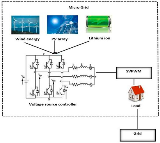
Figure 1.
MG concept.
The rest of this research work is described in following sections. Section 2 describes the objective function formulation to regulate the control of voltage/frequency in the standalone MG. Section 3 presents the proposed hybrid MOSOS-algorithm-based control scheme. In Section 4, simulation results and performance comparisons are discussed. Finally, Section 5 presents the conclusion of this paper.
2. Formulation of Four Single-Objective Functions
The proposed multiobjective optimization issue comprises objective capacities, for example, voltage overshoot/undershoot, rise time, settling time, and integral time absolute error (ITAE), which are to be limited for tuning the PI controller. The objective capacities are clarified in the accompanying subsection.
2.1. Overshoot/Undershoot Percentage
Voltage/current wave reflection occurs when there is a mismatch in the state of impedance on both sender and receiver end. Overshoot/undershoot causes distortion in the output reflected wave. Overshoot is a reflection of signal or function exceeding the target value and vice versa for undershoot. The level of overshoot/undershoot is determined as given in Equation (1).
where represent the maximum and step value, respectively, in Equation (2).
2.2. Rise Time
The time taken by voltage/current response in terms of pulse to rise from 10% to 90% of the set target value is referred to as rise time (Tr). The rise time is determined in Equation (3) and the rise time function is determined as given in Equation (4).
where is the rise time and represent the time at which the output of the system under analysis is at the x% and y% (10% and 90%) of its steady-state value, respectively. and represent the value of the rise time before and after optimization, respectively.
2.3. Settling time
The time taken by the response to accomplish and keep up a certain scope of level of definite value is referred to as settling time. The settling time is determined in Equation (5) and the objective function is determined as given in Equation (6).
where indicate before and after settling time of single-objective optimization, respectively.
2.4. Integral Time Absolute Error (ITAE)
The objective function ITAE has some error integrating functions such as integral absolute error (IAE), integral time squared error (ITSE), and integral square error (ISE). The ITAE objective function is one of the objective functions for our proposed system that needs to be minimized because it gives realistic responses and unrealistic assessment. The ITAE index is calculated as given in Equation (7).
where represent the value of ITAE before and after single-objective optimization, respectively.
3. Proposed Hybrid MOSOS-Algorithm-Based Control Scheme
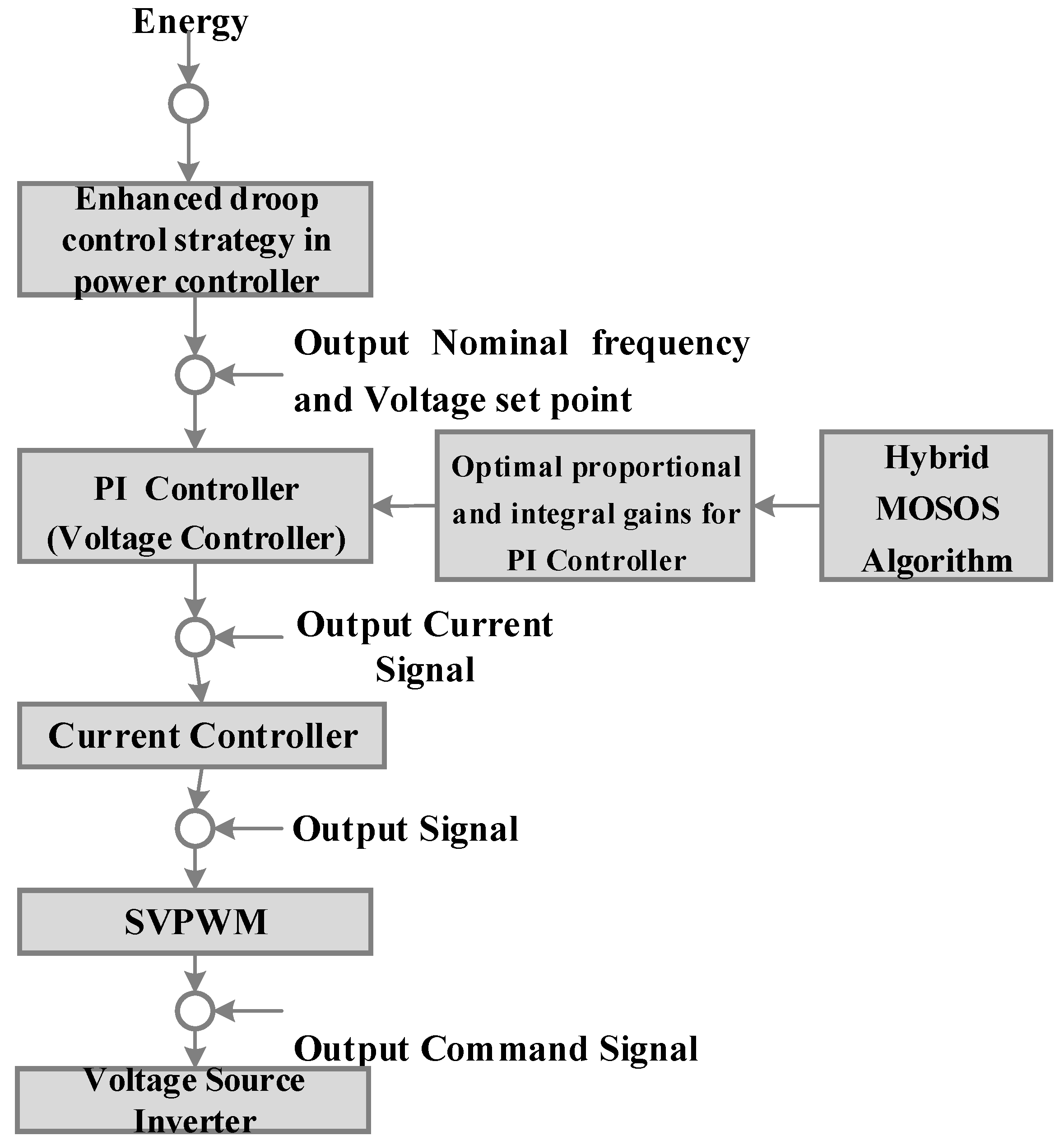
Figure 2 demonstrates the flow graph of the control scheme for the voltage source controller in the MG. The proposed control system comprises energy, voltage, and current controllers with proportional-integral (PI) controllers along with the hybrid MOSOS algorithm. The improved droop control design is utilized for the power control methodology in the proposed MG. Then, the objective functions are considered as the input of the optimization algorithm to find a Pareto set of optimal solutions.

Figure 2.
Flow diagram of control scheme for voltage source controller.
To enhance the absolute model response for the voltage controller utilizing the fuzzy principle, the development of voltage controller and current signal goes about as the contribution to the current controller to evacuate the present error. The error-free, current-controlled signals are then sustained as a contribution to the space vector width modulator, which creates the signals required for the voltage source inverter. The structure of the controller and the parts of the controllers will be clarified in the consequent section. The underneath stream plan shows the proposed control scheme for independent MGs.
3.1. Enhanced Droop Control Strategy in Power Controller
Enhanced droop control strategy is made as the core of the voltage source inverter frequency-controlled method. Furthermore, it plays a major role for attaining the control of transmission power. While considering the active as well as the reactive power in the inductive transmission line, both depend on power angle and voltage difference, respectively. The droop control strategy in an MG simulates various droop features of the conventional power system. This is done by means of varying the outputs of both active and reactive power, so as to control the amplitude and frequency of the output voltage. Thus, the voltage node in the island operation mode is stabilized accordingly with this proposed MG system. The droop control analysis is given in Equations (9) and (10).
To overcome the above-mentioned issue, the enhanced droop control scheme proposed in [11] for reactive power sharing among inverters is given by Equation (11)
where is the nominal value of V and is the shaped voltage reference of the droop controller. Once the power development has achieved the reference value, the voltage stays steady and consistent without any variations until the point where it reaches alternate set point value. At whatever point there is an increment in stack, the conveyed set point takes after the yield control conveyed by every converter and the voltage is managed.
With VSC (Voltage Source Converter), the first step is to update its phase and frequency information, whereas the frequency and phase of the generated signal relative to the MG voltage are analyzed. Hence, the precise amount of active and reactive power is introduced onto the MG. For every half-cycle, the frequency information is updated by calculating the frequency information updates during every half-cycle by measuring the sum of time distributed among the two positive zero-crossings and negative zero-crossings of the MG voltage. Thus, for every update in frequency, the entire time period is measured.
Active power of the system is calculated based on Equation (12) and reactive power of the system is calculated based on Equation (13). δ is the power angle measured between real and reactive power and can be calculated by using Equation (13).
Hence, the power controller uses the enhanced droop control strategy to compute the nominal frequency and voltage set point from Equations (11) and (12). The output values of the power controller act as the input of the voltage controller.
Impact of Frequency Threshold
Equation (14b) depicts that the UFLS (under-frequency load shedding) is not applicable when the system operating frequency is higher than the threshold frequency (in Hz) and the amount of load shedding is proportional to frequency deviation and is given in Equation (14b).
3.2. Hybrid MOSOS Algorithm for Tuning the PI Controller
In this proposed control scheme, we propose a hybrid MOSOS algorithm based on simulated annealing for finding out the best optimal solution for the voltage controller. The proposed PI controller along with the hybrid MOSOS algorithm is implemented to control the voltage deviation due to the variation in load. The tuning of and in PI controllers is designed as a multiobjective optimization problem taking into consideration the MOSOS algorithm. The and values of the controller are set in such a way that the output obtained has minimum settling time, rise time, overshoot, and ITAE to attain proper voltage control. The proposed hybrid MOSOS algorithm is modeled by the equations given from Equation (15) to Equation (20). The nature of the position of the organism relies upon the state which characterizes the degree of adjustment of the organism to the biological system. The state is obtained by utilizing the objective capacity given in Equation (25) that takes after the imperatives shown in Equation (26). Each organism represents the objective function for the tuning of the PI controller.
where represents the organism with best fitness value evaluated from Equation (25). and . represent the assistance factor between the organism and , respectively. In Equation (18), U (−1, 1) is a vector quantity of uniformly distributed random numbers between −1 and 1. Xv is updated to
This procedure increments the state in identifying the universal target. For every iteration process, a new solution is identified and the present solution will be the superior one to the previous solution. Error is calculated from the identified and previous solution. To get better arrangements, the accompanying conditions have to be fulfilled as stated in Equations (19) and (20).
Moreover, the simulated annealing (SA) algorithm is used along with the procedure of mutualism and commensalism phases of the SOS (Symbiotic organisms search) to enhance the speed of convergence and quality of solution and to approximate the global optimum of a given function. SA is a probabilistic strategy which is considered to be a very powerful optimization strategy. This annealing procedure is often used where the search space is discrete. The SA algorithm demands the feature linked to temperature variations to be embedded in the operational characteristics of the algorithm. The variation in the temperature and inner increment in energy cause the particles to scatter and the cooling procedure is connected, as requested by the particles. The innermost energy is limited as the temperature achieved is in room state. The recreated annealing calculation is acquired by utilizing the interior state of the objective capacity and temperature advancement as the control parameter. The temperature in the SA process primarily influences the worldwide search execution of SA calculation. At high introductory estimation of temperature, the SA will have a high shot of finding worldwide ideal arrangement which, as a result, expands the calculation time. On the other hand, when the estimation of introductory temperature is low, the possibility of the calculation finding worldwide ideal arrangement is constrained, however, the calculation time will be shorter. The parameters and f(Xu) are the fitness functions for tuning the PI controller and the temperature is a control parameter to provide global optimization with limited time and is represented in Equation (22). The SA probability of accepting neighbor solution into a new generation of organisms is given in Equation (21).
where and f(Xu) are the fitness function to control parameter . T0 represents the initial temperature, is the final temperature. The pseudo code of the hybrid MOSOS algorithm (Algorithm 1) is given below.
| Algorithm 1 Pseudo code of hybrid MOSOS algorithm |
| Update according to Equation (19) |
| Transform using mapping function given above |
| Identify the best organism |
| End For |
| End While |
This proposed hybrid MOSOS algorithm gives the Pareto set of solutions used for finding the next generation of organisms based on nondominated sorting and crowding distance for simultaneous computations.
3.3. Crowding Distance for Finding the Optimal Solution from Nondominated Solution
The result obtained in crowding distance estimation gives a gauge of the ideal arrangements and this procedure improves the situation of every objective capacity. The summation of all individual objective capacities can shape the preceding crowding distance.
Hence, the Pareto solution can be found by crowd distance. Then, the optimal solution can be determined from the crowd distance value by using the fuzzy decision maker.
3.4. Fuzzy Decision Maker for Optimal Solution in Voltage Controller
The fuzzy decision maker is used to choose the optimal Pareto solution from the Pareto set. All the objective functions are fuzzified in membership function. The objective function being minimized, the membership function can be represented as shown in Equation (23).
where represent the minimum and maximum values of the objective function, respectively, and , are the values of membership function and objective function, respectively, in the Pareto set k.
The overall membership function calculated by using its individual membership function can be represented as shown in Equation (24).
where, are the weighting factors of the objective function. The proposed MOSOS algorithm constructs and minimizes the cost function as shown in Equation (25).
This proposed optimization problem (25) is optimized subject to the following constraints of PI controller parameter limits given in Equation (26).
Finally, on eight exchanging combinations, the most astounding participation capacity of Pareto arrangement can be picked as the best ideal response for the voltage controller. In the proposed control scheme, the controller accepts the contribution from the voltage controller as an existing flag and the existing controller exhibits the present state error. The present state errors adjust the width of the pulse in the space vector pulse width module (SVPWM) and develop eight states for three-stage VSC. The switching combinations are dual codes. Depending on the parallel code, the switches are turned ON and its particular current information is controlled. After that, a signal is created for the voltage source inverter to manage the voltage and frequency. Here, the inputs are solar power, wind power, demand, and SB power. The time parameter is taken as the output current simulation time at definite rate.
3.5. PI Controller for Voltage Controller
The proposed PI controller along with the hybrid MOSOS algorithm is implemented to control the voltage deviation due to the variation in load. The tuning of and in PI controllers is designed as a multiobjective optimization problem taking into consideration the MOSOS algorithm. A basic PI controller having and as proportional and integral pick-up, respectively, is utilized for tuning the PI controller. In an islanded MG, after a stack change, parameters of the PI controller are strongly adjusted to get the most ideal working point that fulfills the objective capacities. The fundamental PI controller outline is given underneath and is shown in Figure 3.
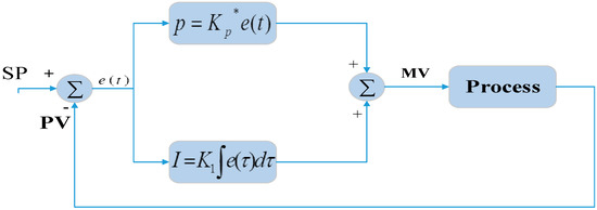
Figure 3.
Block Diagram of PI Controller.
The controller output in this case is given in Equation (27).
Figure 3 demonstrates the block diagram square graph PI controller in an integral error pay scheme; the yield reaction depends in some way upon the integral of the impelling sign. This sort of pay is presented by utilizing a controller, which delivers a yield flag comprising two terms, one proportional to the impelling sign and the other proportional to its integral. Such a controller is called proportional in addition to the integral controller or PI controller. In the PI controller, given more qualities so advanced that esteem utilizing the MOSOS calculation to locate an ideal answer to produce the present flag for the current controller, which is clarified in the following section.
3.6. Current Controller
In our control structure, the current controller receives the input from the voltage controller that is the current signal. After receiving the current signal, the current controller removes the current error. Then, the resulting signal is entered into the SVPWM, which is explained in the below subsection.
The space vector pulse width modulation uses the current signal received from the current controller for generating command signals for the voltage source inverter. The space vector pulse width modulation has some steps to eliminate the harmonics and find the desired output signal.
To acquire threshold, the threshold value of counter causes greater reliability of the proposed method.
4. Results and Discussion
In this paper, we have proposed a control scheme for the voltage and frequency regulation in standalone MGs utilizing a hybrid simulated-annealing-based multiobjective symbiotic organism search algorithm. This section gives the portrayal of the outcomes obtained from the proposed strategy and the investigation with the current research is likewise communicated.
4.1. Simulation Setup
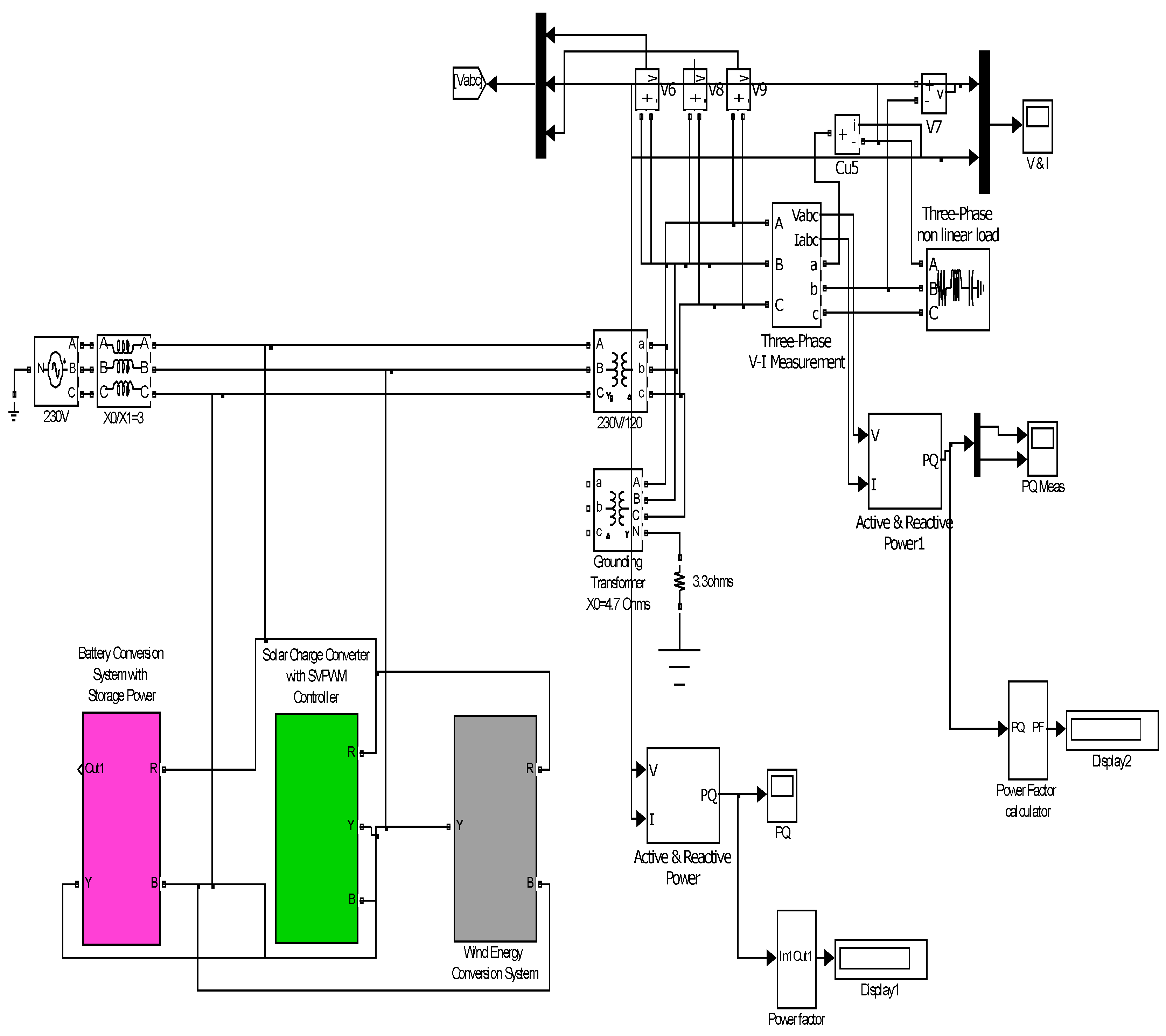
Figure 4 shows the simulation model of the MG designed using battery power conversion system, solar conversion system, and wind-power conversion system.
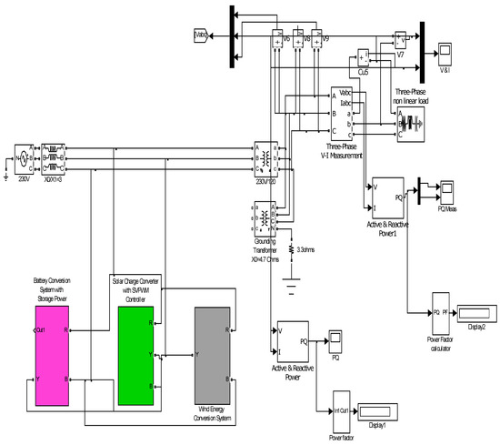
Figure 4.
Microgrid simulation model.
Simulation Scenario Design
Let us consider harmonic and fluctuating sources as interference in the designed scenario for power quality analysis.
When considering harmonic sources in MGs, basic scenarios are firstly designed according to daily operation data under grid-connected mode and standalone mode. Major harmonic sources are not included in basic scenarios, but background harmonic sources are included. For comprehensiveness and representativeness, factors including the quantity, location, order, magnitude, and phase of major harmonic sources are to be considered in scenario design. After simplification, typical scenarios with harmonic sources in MGs are designed as shown in Table 1, in which GC stands for grid-connected, SA stands for standalone, and MG stands for microgrid.

Table 1.
Typical simulation scenarios with harmonic sources.
4.2. Proposed Control Scheme Results
The results are figured out for each block of the system such as powergrid, PV plant, solar plant, inverter, controller.
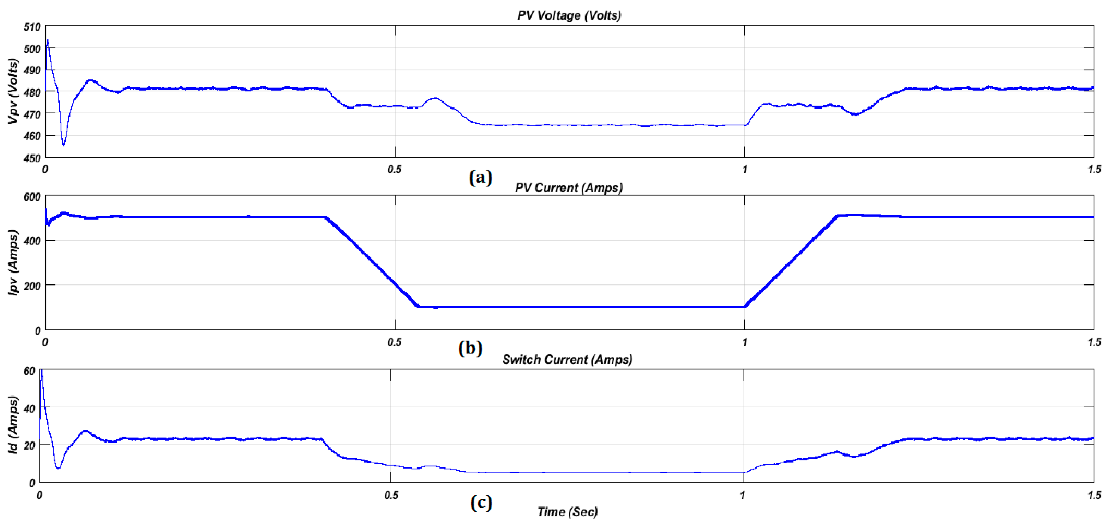
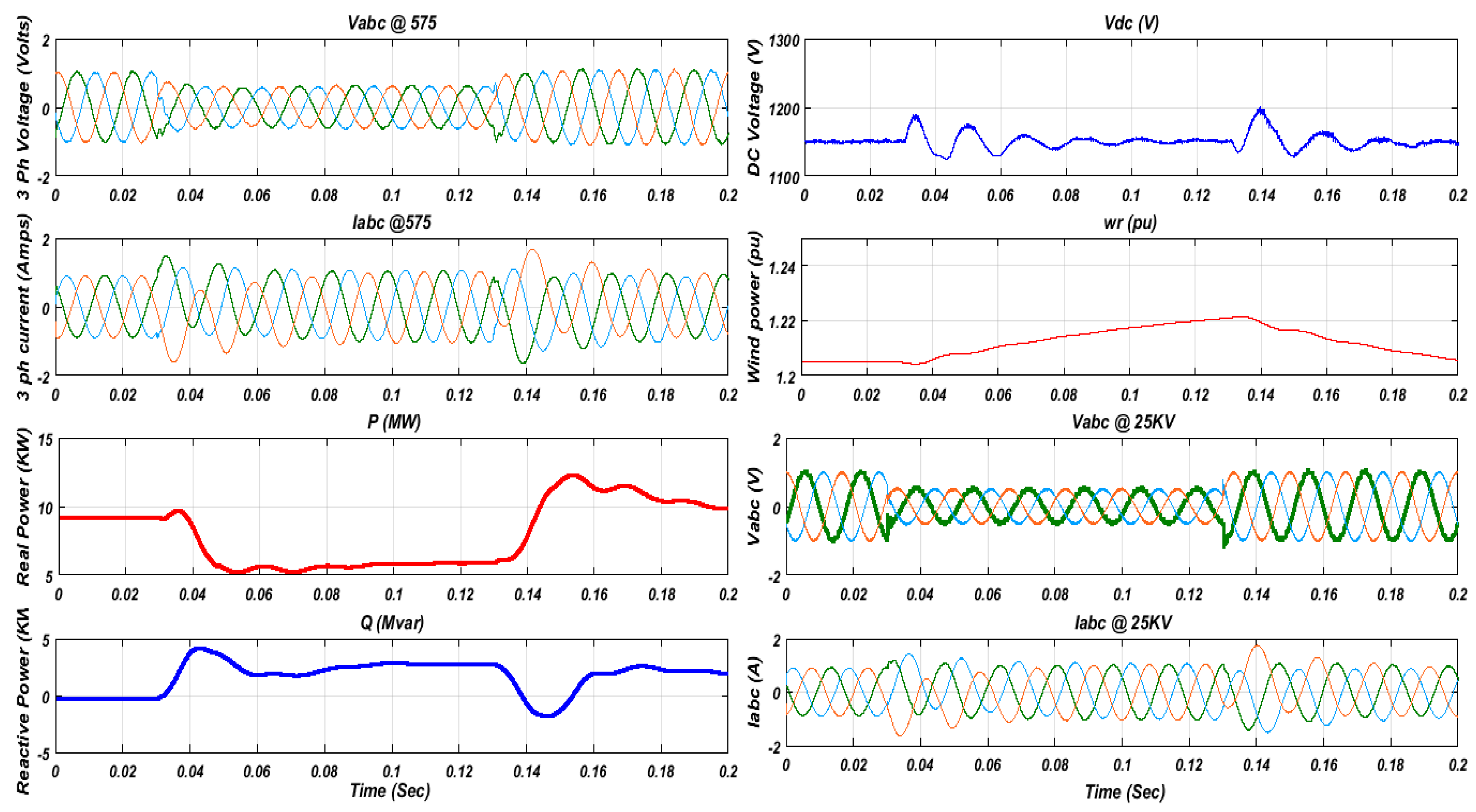
The solar plant (Figure 5) is a commonly used renewable resource in the MG since it provides limitless power and has a low cost. In our proposed implementation, we have also employed solar as one of the renewable resources. A photovoltaic system operates in maximum power point tracking and injects the available power to the grid in consideration of the system stability. The simulation results obtained for solar and wind plants in terms of power, voltage, and current are demonstrated in the following Figure 6 and Figure 7.
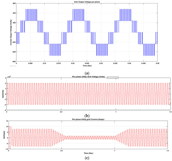
Figure 5.
Utility grid results: (a) power output, (b) voltage generated from grid for three phases, (c) current generated from grid for three phases.
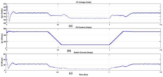
Figure 6.
Solar plant results: (a) PV voltage, (b) PV current, (c) switch current.
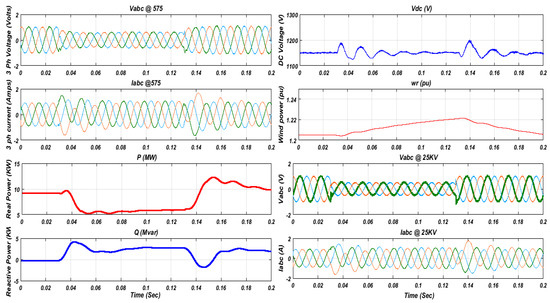
Figure 7.
Wind farm results for 575 V and 25 KV.
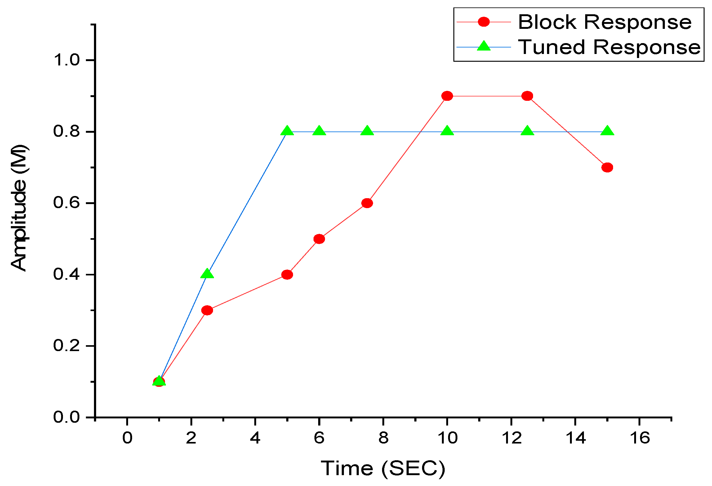
Initially, the PI controller receives the signal from the power controller that is not tuned, so the signals are not stable. Figure 8 shows with and without tuning the PI controller generating the signal.

Figure 8.
Tuning with and without PI controller using hybrid MOSOS-SA.
The main aim of the PI controller is to stabilize the signal from the power controller, so the hybrid MOSOS algorithm is used to tune the PI controller.
The control structure proposed for the PI controller regulation is shown in Figure 9; implementation is carried out here by commanding certain perturbations and the hybrid MOSOS is activated. The optimal values obtained from the MOSOS algorithm are shown in Table 2.

Figure 9.
Inverter result from control structure.
Table 2.
Optimal PI values.
The time interval for tuning the PI controller is defined as [0, 1]. It shows that the optimal PI values are 0.30474 and 8.0823 of the controller for the minimum objective function 0.0103 obtained from the MOSOS algorithm. The obtained results show the system response with minimum rise time of 0.17, settling time of 1.5, overshoot percentage of 14.9%, and IATE of 0.15. The number of eco-sizes and hybrid MOSOS algorithm are fixed at 20 and 10, respectively. The search space of parameters KP and KI is considered in the range of [0, 0.5] and [0, 1000], respectively. The extents utilized as a part of the recreations are chosen as per before Considerations. As said in Section 3, the PI controller was utilized as a part of the balanced online as opposed to the present controller. In this investigation, three DGs were utilized since the motivation behind this examination was to demonstrate the ideal execution; be that as it may, the technique can be effectively reached out to keep running with multiple DGs.
4.3. Comparative Analysis
Table 3 describes the brief contraction between the existing methods and the proposed method.
Table 3.
MOSOS comparison.
The above Table 3 conveys the examination of our proposed hybrid SA-MSOS strategy with the other three existing techniques. The proposed control plot is contrasted with a couple of contending algorithms. Since there is no work in writing with an indistinguishable objective capacity from our strategy, we here research the strategies limiting the ITAE objective capacity since it is more utilized as a part of writing. The second segment of the table gives the occasions for which the ITAE is limited. In this table, a hybrid MOSOS strategy is executed in this paper. The current techniques MOSOS, MOHBB-BC, MOPSO are utilized to take care of the optimization issue of limiting Table 3. These qualities are more ideal than different qualities recorded in the table.
Thus we can conclude that the proposed control structure is well suited for the removal of voltage/current error and stabilizing the signal for the voltage and frequency regulation in standalone MGs. Thus the above-described simulation results and the correlations reveal that the novel MOSOS strategy has a superior capacity in obtaining a more ideal arrangement.
5. Conclusions
The proposed PI controller along with the hybrid MOSOS algorithm is implemented to control the voltage deviation due to the variation in load. The tuning of and in PI controllers is designed as a multiobjective optimization problem taking into consideration the MOSOS algorithm. Looking at the simulation test results shown in Table 3, the proposed hybrid MOSOS results are and . Thus with the proposed PI controller with this work, the voltage as well as the frequency regulation of an inverter achieves a better solution with a standalone MG. Several key functions of voltage including ITAE, overshoot/undershoot time, settling time, and rise time are optimized to attain an even and effective response. As per the discussion, the proposed hybrid SA-MSOS has minimal iterations compared to other methods. Moreover, the simulation outcomes show an improved solution.
Author Contributions
Conceptualization, Y.T., R.K., S.N. Funding acquisition, Y.T., R.K., S.N. Investigation, Y.T., R.K., S.N. Writing, original draft, Y.T., R.K., S.N. Writing, review and editing, Y.T., R.K., S.N.
Funding
This research received no external funding.
Conflicts of Interest
The authors declare no conflict of interest.
References
- Kundur, P.; Paserba, J.; Ajjarapu, V.; Andersson, G.; Bose, A.; Canizares, C.; Hatziargyriou, N.; Hill, D.; Stankovic, A.; Taylor, C.; et al. Definition and classification of power system stability IEEE/CIGRE joint task force on stability terms and definitions. IEEE Trans. Power Syst. 2014, 19, 1387–1401. [Google Scholar]
- Shun, T.Z.; Logenthiran, T.; Srinivasan, D. Demand Side Management in Smart Grid Using Heuristic Optimization. IEEE Trans. Smart Grid 2012, 3, 1244–1252. [Google Scholar]
- Chen, C.; Duan, S.; Cai, T.; Liu, B.; Hu, G. Smart energy management system for optimal microgrid economic operation. IET Renew. Power Gener. 2011, 5, 258–267. [Google Scholar] [CrossRef]
- Xue, M.; Geng, G.; Jiang, Q. Energy Management of Microgrid in Grid-Connected and Stand-Alone Modes. IEEE Trans. Power Syst. 2013, 28, 3380–3389. [Google Scholar]
- Basak, P.; Dey, S.H.N.; Chowdhury, S. A literature review on integration of distributed energy resources in the perspective of control, protection and stability of microgrid. Renew. Sustain. Energy Rev. 2012, 16, 5545–5556. [Google Scholar] [CrossRef]
- Bidram, A.; Davoudi, A. Hierarchical Structure of Microgrids Control System. IEEE Trans. Smart Grid 2012, 3, 1963–1976. [Google Scholar] [CrossRef]
- Guerrero, M.; JosepLoh, P.C.; Lee, T.Z.; Chandorkar, M. Advanced control architectures for intelligent microgrids—Part II: Power quality, energy storage, and AC/DC micro grids. IEEE Trans. Ind. Electron. 2013, 60, 1263–1270. [Google Scholar] [CrossRef]
- Sao, C.; Lehn, P. Control and Power Management of Converter Fed Microgrids. IEEE Trans. Power Syst. 2008, 23, 1088–1098. [Google Scholar] [CrossRef]
- Serban, E.; Serban, H. A Control Strategy for a Distributed Power Generation Microgrid Application with Voltage- and Current-Controlled Source Converter. IEEE Trans. Power Electron. 2010, 25, 2981–2992. [Google Scholar] [CrossRef]
- Bolsens, B.; Woyte, A.; De Brabandere, K.; Keybus, J.V.D.; Driesen, J.; Belmans, R. A Voltage and Frequency Droop Control Method for Parallel Inverters. IEEE Trans. Power Electron. 2007, 22, 1107–1115. [Google Scholar]
- Jinwei, H.; Li, Y.W.; Munir, M.S. Flexible harmonic control approach through voltage-controlled DG—Grid interfacing converters. IEEE Trans. Ind. Electron. 2007, 59, 444–455. [Google Scholar]
- Masaki, M.S.; Zhang, L.; Xia, X. Hierarchical Power Flow Control of a Grid-tied Photovoltaic Plant Using a Battery-Supercapacitor Energy Storage System. Renew. Energy Integr. Mini Microgrid 2018, 145, 32–37. [Google Scholar]
- Mehrasa, M.; Pouresmaeil, E.; Mehrjerdi, H.; Jørgensen, B.N.; Catalão, J.P.S. Control technique for enhancing the stable operation of distributed generation units within a microgrid. Energy Convers. Manag. 2015, 97, 362–373. [Google Scholar] [CrossRef]
- Chung, I.Y.; Liu, W.; Cartes, D.A.; Collins, E.G.; Moon, S.I. Control methods of inverter-interfaced distributed generators in a micro grid system. IEEE Trans. Ind. Appl. 2010, 46, 1078–1088. [Google Scholar] [CrossRef]
- Li, Y.; Li, Y.W. Power Management of Inverter Interfaced Autonomous Microgrid Based on Virtual Frequency-Voltage Frame. IEEE Trans. Smart Grid 2011, 2, 30–40. [Google Scholar] [CrossRef]
- Bevrani, H.; Habibi, F.; Babahajyani, P.; Watanabe, M.; Mitani, Y. Intelligent Frequency Control in an AC Microgrid: Online PSO-Based Fuzzy Tuning Approach. IEEE Trans. Smart Grid 2012, 3, 1935–1944. [Google Scholar] [CrossRef]
- Abido, M.A.; Hassan, M. Optimal Design of Microgrids in Autonomous and Grid-Connected Modes Using Particle Swarm Optimization. IEEE Trans. Power Electron. 2011, 26, 755–769. [Google Scholar]
- Hu, J.; Zhu, J.; Dorrell, D.G.; Guerrero, J.M. Virtual Flux Droop Method—A New Control Strategy of Inverters in Microgrids. IEEE Trans. Power Electron. 2014, 29, 4704–4711. [Google Scholar] [CrossRef]
- Guerrero, J.M.; Vasquez, J.C.; Matas, J.; De Vicuna, L.G.; Castilla, M. Hierarchical Control of Droop-Controlled AC and DC Microgrids—A General Approach Toward Standardization. IEEE Trans. Ind. Electron. 2011, 58, 158–172. [Google Scholar] [CrossRef]
- Micallef, A.; Apap, M.; Spiteri-Staines, C.; Guerrero, J.M.; Vasquez, J.C. Reactive Power Sharing and Voltage Harmonic Distortion Compensation of Droop Controlled Single Phase Islanded Microgrids. IEEE Trans. Smart Grid 2014, 5, 1149–1158. [Google Scholar] [CrossRef]
- Son, S.; Han, S.; Roh, J.H.; Lee, D. Optimal Offer Strategies for Energy Storage System Integrated Wind Power Producers in the Day Ahead Energy and Regulation Markets. J. Electr. Eng. Technol. 2018, 23, 2236–2244. [Google Scholar]


© 2019 by the authors. Licensee MDPI, Basel, Switzerland. This article is an open access article distributed under the terms and conditions of the Creative Commons Attribution (CC BY) license (http://creativecommons.org/licenses/by/4.0/).