Article

Observer-Based Sliding Mode FTC for Multi-Area Interconnected Power Systems against Hybrid Energy Storage Faults

School of Internet of Things Engineering, Jiangnan University, Wuxi 214122, China
*
Author to whom correspondence should be addressed.
Energies 2019, 12(14), 2819; https://doi.org/10.3390/en12142819
Submission received: 24 June 2019 / Revised: 12 July 2019 / Accepted: 15 July 2019 / Published: 22 July 2019
(This article belongs to the Section F: Electrical Engineering)

Abstract

:
An observer-based sliding mode fault-tolerant controller is developed in this paper, which is applied to an interconnected power system with a hybrid energy storage system (HESS). The model of the interconnected power system with HESS is introduced first. An observer is then proposed to estimate the unknown but bounded load disturbances and the actuator fault. The sliding mode fault-tolerant controller is further designed based on the observer ensuring that the area control error of the interconnected power system asymptotically converges to zero. The stability and the convergence of the whole system are proven based on the Lyapunov stability theory. Finally, the effectiveness of the proposed fault-control scheme is demonstrated through simulations.

1. Introduction

Centralized power supply systems have some limitations since they require high power quality and strong reliability. In the modern power grid, the power system network is composed of several interconnected subsystems. Stable power system operations require that the total generation of each interconnected area meets the whole load demands as well as the associated power system losses. The control problem is known as load frequency control (LFC) [1,2,3,4,5].
Various approaches of LFC have been proposed since the 1970s, e.g., classical control [6], adaptive control [7], robust control [8], sliding mode control [9], predictive control [10], and artificial intelligence control [11]. At present, primary frequency modulation technology is mainly used for load frequency stabilization of the power system, i.e., LFC is used to maintain the system frequency at rated value. Specifically, power generation and the system load are matched by adjusting the generator set such that the area control error (ACE) is zero. However, integrating photovoltaic and wind power generation systems, electric-vehicle charging stations, and other new components into the scaled power systems brings new issues such as harmonic pollution, voltage instability, and non-linearity, is spite of the enhanced controllability and flexibility.
LFC of distributed hybrid energy storage systems can effectively improve the above-mentioned situation [12,13,14]. It is mainly used to suppress the power fluctuations and reduce the violent oscillation of the system and the peak-valley difference of the load power curve, thereby enhancing the power quality of the power grid. Therefore, in order to ensure the active power balance of the power system and eliminate a series of negative effects brought by fluctuating power, it is necessary to adopt distributed hybrid energy storage equipment to adjust the fluctuating power. Several types of advanced energy storage technologies can be considered for the energy storage of a multi-area interconnected power system, e.g., lithium battery [15], electrochemical energy storage [16], superconducting magnetic energy storage [11,12,13], super capacitor energy storage [12,17], pumped-energy storage [18], flywheel energy storage [19]. Developing the electric load microforecasting modules in the energy management system provides a chance to optimally control the energy distribution in the power system [20]. However, any electronic component has a limited lifetime. When a large number of hybrid energy storage devices connect a power system, the system complexity is increased, which may degrade the reliability of the power system. It is crucial to avoid system faults in order to guarantee reliability.
Fault-tolerant control (FTC) plays an important role in controlling power systems. Abundant results on FTC have been achieved in the last three decades [21,22,23,24]. It maintains the normal operation of a power system, given that the system components partially fail. Thus FTC provides an approach to improve the reliability of power systems.
A multi-area interconnected power system has the characteristics of many subsystem interconnections. Because each subsystem has different dynamic characteristics, it is difficult to design the fault-tolerant control scheme with a single system model. To solve this problem, the use of interconnected system modeling is an effective method. At present, to ensure that interconnected systems work as expected, a lot of work focuses on the off-line design of interconnected systems. However, faults will suddenly change the behavior of the coupling mechanism of subsystems; furthermore, fault-tolerant control strategies must be applied online, which brings great challenges to theoretical research. Cyprus’ Polycarpou team has made a series of contributions in this direction [25,26]. The main idea is to treat coupling terms as uncertainties of subsystems, and then use robust fault-tolerant control method to design the controller to compensate for the effects of coupling terms on subsystems, so as to realize the robustness of subsystems to coupling terms. In [27], a distributed adaptive state feedback robust tracking control strategy is studied for linear interconnected systems with actuator faults, coupling faults, and external disturbances. In [28], a distributed fault-tolerant control strategy based on a fuzzy adaptive observer is proposed by studying the nonlinear interconnected system with actuator faults and unknown functions. The authors of [23] analyze the influence of all coupling mechanisms on the performance of the whole system from a global perspective, establish the global fault-tolerant condition by using the small gain principle [29], and design a distributed fault-tolerant control strategy that compensates the coupling terms through the co-regulation of subsystems.
Motivated by the aforementioned investigation, an active fault-tolerant control scheme is proposed for the multi-area interconnected power system under load disturbances and actuator faults. Initially, the mathematical model of a power system with a hybrid energy storage system (HESS) using an actuator and the mathematical model of an actuator fault is introduced. Secondly, the observer-based sliding mode fault-tolerant controller is designed for a multi-area interconnected power system with HESS by using a sliding mode approach and designed observer. Lastly, comparisons of the response to step actuator fault, computational burden, and robustness are made between several existing control methods. The results confirm the superiority of the proposed FTC technique.
The remainder of this paper is organized as follows. Section 2 presents the mathematical model of a multi-area interconnected power system with HESS and actuator fault. Section 3 details the observer and sliding mode fault-tolerant controller. Section 4 shows a simulation, with a comparison to several control schemes. Section 5 presents some conclusions. The notations used in this paper are introduced in Table 1.

2. Problem Formulation

This section first formulates the mathematical model of the interconnected power system and then describes the hybrid energy storage system and actuator fault modeling. Figure 1 shows the topology map of a multi-area interconnected power system with HESS.

2.1. Mathematical Modeling

A power system is known as a complex nonlinear dynamic system, which is always affected by small load disturbances, leading to load frequency fluctuation. The objectives of the LFC are: (1) ensuring the frequency deviation of each area at a constant range against load changes and system disturbances [1], (2) maintaining the tie-line power interchanges with neighboring areas at a pre-specified value [30]. Generally speaking, the power system could be linearized around an operating point to establish a dynamic system model for control purposes. The linearized model of governor, steam turbine, and generator are expressed, respectively, as
G g i = 1 T g i s + 1 ,
G p i = 1 T t i s + 1 ,
G p i = K p i T p i s + 1 .
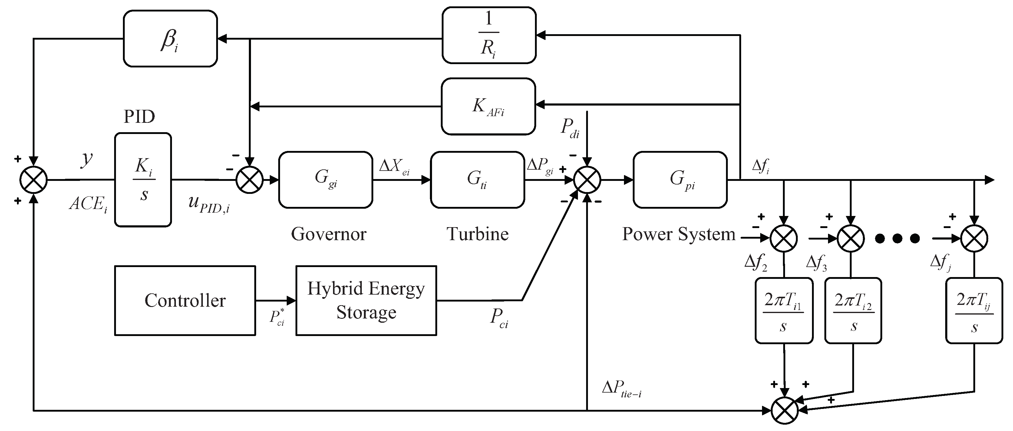
The block diagram of the interconnected power system with HESS is illustrated in Figure 2. The state space model of the controlled system can be represented as
Δ f ˙ i = 1 T P i Δ f i + K P i T P i P g i K P i T P i Δ P t i e , i K P i T P i P d i K P i T P i P c i ,
P ˙ g i = 1 T T i P g i + 1 T T i X e i ,
X ˙ e i = ( 1 R i + K A F i ) T G i Δ f i 1 T G i X e i 1 T G i A C E i ,
A C E i ˙ = Δ P t i e i + B i R i Δ f i .
The tie-line power flow between areas i and j can be described as
Δ P ˙ tie i j = 2 π T i j Δ f i T i j Δ f j , Δ P tie i j = Δ P tie j i ,
and the total tie-line power flow between area i and other areas can be calculated as
Δ P ˙ tie , i = 2 π j = 1 , j i n Δ P ˙ tie i j = 2 π j = 1 , j i n T i j Δ f i j = 1 , j i n T i j Δ f j .
ACE is usually used to represent the mismatch between the power generation and the area load. Hence, it is selected as the controlled variable in our control problem. The A C E i for area i can be expressed as
A C E i = Δ P tie , i + φ i Δ f i ,
φ i = β i R i ,
where φ i denotes the frequency deviation constant. Without loss of generality, with a set of state variables x i = [ Δ f i P g i X e i A C E i Δ P t i e i ] T , the control input u i = P c i , the load disturbance input f i = P d i , and the coupling term
h i j ( t ) = j = 1 , j i n A i j x j ( t ) + B i j u j ( t ) ,
and the partitioned model for subsystem i of a multi-area interconnected power system can be described as following state space model
x ˙ i ( t ) = A i i x i ( t ) + B i i u i ( t ) + B i i f i ( t ) + h ij ( t ) ,
y i ( t ) = C i x i ( t ) .
For the ease of the reader, Appendix A details the state-space representation of the multi-area power system.

2.2. Hybrid Energy Storage System and Actuator Fault Modeling

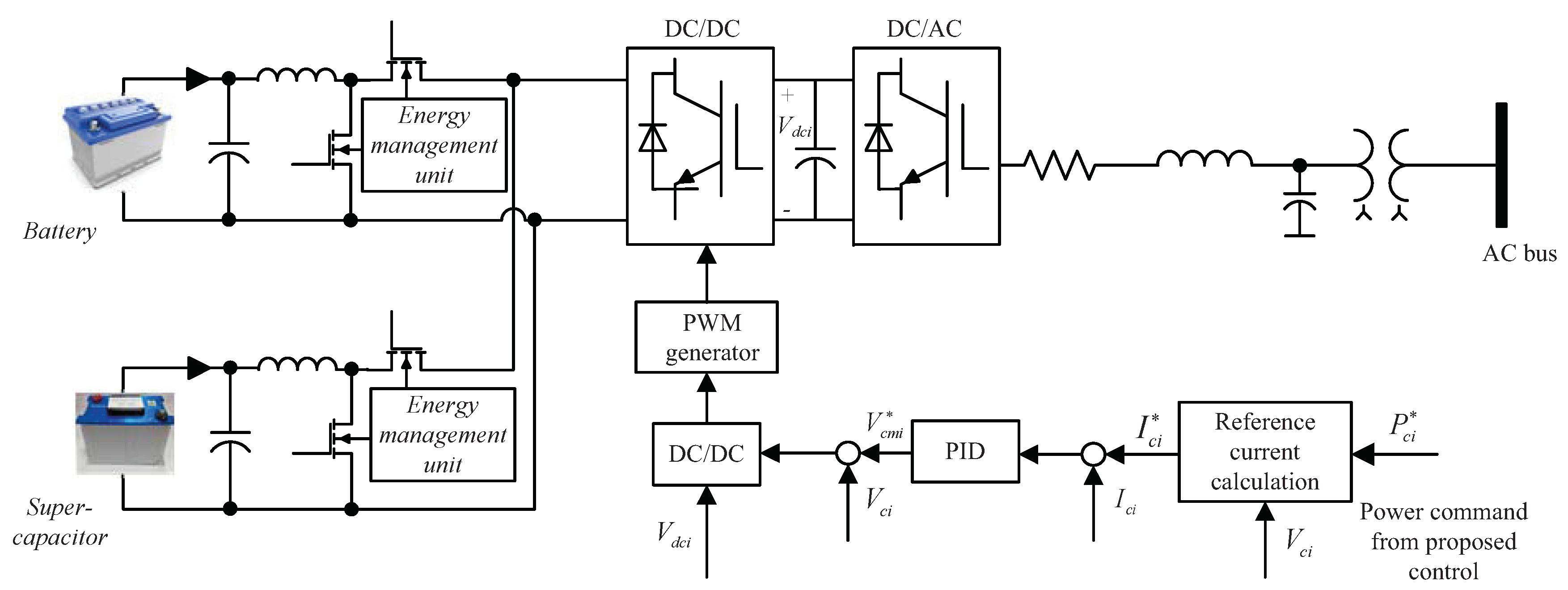
The details of the HESS are shown in Figure 3. The control method of AC/DC converter stabilizes the DC bus voltage and is connected to the HESS. According to the reference power signal, the control method of DC/DC converters realizes the bidirectional power flow between the power grid and the HESS. A given reference power signal enables bidirectional power flow between the grid and the HESS [13]. P c i * is the power command output by the active fault-tolerant controller designed in this paper and then converted to the corresponding current command I c i * by calculation. Then the PID controller converts the received command for the DC/DC converter that controls the energy exchange between the HESS and the power system.
For the purpose of designing a fault-tolerant controller, the actuator fault model is introduced in this study. It is well known that the actuator may be affected by the following two types of fault:
Loss of efficiency fault—the aging of internal energy storage devices, battery capacity reduction, slow charge, and discharge response, etc., resulting in a lower output power.
Bias fault—when the HESS is frequently charged and discharged, the supercapacitor generates a huge discharge current, and meanwhile, the battery is easily overheated and other factors cause damage to the device so that the energy storage system cannot fully respond to the control signal.
The fault of actuators may lead to severe vibration of power system, increase the peak and valley difference of the load power curve, leading to frequency fluctuation of the power grid. In this paper, only the actuator faults occurring in the HESS are considered. Therefore, the actual control signal u i in actuator fault case can be described as follows:
u i ( t ) = u c i ( t ) + p i ( t T ) [ ( e i 1 ) u c i ( t ) + u f i ( t ) ] = u c i + u f i ,
where u c i is the normal control signal in the healthy actuator case of the i-th area, e i represents the efficiency factor of each HESS, and u f i is the bias fault input that enters the actuators in an additive form. Denote p i ( t T ) as the occurrence of an actuator fault, which is described by
p i t t i = 0 if t < t i 1 if t t i .
Through Equation (13), we synthesize the possible bias fault and efficiency loss fault of the actuator into u f i . We can design the fault-tolerant controller by adopting the method of dealing with additive faults. The system (11) and (12) with actuator fault can be written as follows:
x ˙ i ( t ) = A i i x i ( t ) + B i i u c i ( t ) + B i i d i ( t ) + h ij ( t ) ,
y i ( t ) = C i x i ( t ) ,
where d i ( t ) = u f i ( t ) + f i ( t ) represents the lumped disturbances involved in the system.
Before presenting the main results, two assumptions are introduced as follows.
Assumption 1.
The coupling term of the multi-area power system h i j satisfies h i j γ , where γ is a positive scalar.
Assumption 2.
The effects of the lumped disturbances d i and its time derivative d ˙ i are bounded.

3. Main Results

In this section, an FTC scheme using a terminal sliding mode strategy is presented, which is able to detect the occurrence of unknown composite disturbances and maintain system stability. The proposed approach consists of an observer and a fault-tolerant controller, as discussed in the following. The block diagram of the FTC is illustrated in Figure 4.

3.1. Observer Design

An observer is designed for the multi-area interconnected power system with HESS in order to estimate the lumped signals composed of the actuator faults and the bounded load disturbances. The observer has the following form:
x ^ ˙ i ( t ) = H i x i ( t ) x ^ i ( t ) + A i i x i ( t ) + B i i u c i ( t ) + B i i d ^ i ( t ) + γ sgn x ˜ i ( t ) ,
d ^ ˙ i ( t ) = d ^ i ( t ) 1 ρ i B i i T x ˜ i ( t ) ,
where x ^ i is the estimated state, x ˜ i ( t ) = x i ( t ) x ^ i ( t ) is the estimation error, which can be regarded as a sliding mode surface, and H = diag λ 1 , λ 2 , λ 3 , λ 4 , λ 5 > 0 is a positive matrix to be defined in advance.
Subtracting (16) from (14), the observer error dynamic is obtained as
x ˜ i ˙ ( t ) = x i ˙ ( t ) x ^ ˙ i ( t ) = h ij ( t ) γ sgn ( x ˜ i ( t ) ) H i x i ( t ) x ^ i ( t ) + B i i ( d i ( t ) ) d ^ i ( t ) = h ij ( t ) γ sgn ( x ˜ i ( t ) ) H i x ˜ i ( t ) + B i i d ˜ i ( t ) ,
where d ˜ i ( t ) = d i ( t ) d ^ i ( t ) is the lumped disturbances error variable.
In terms of the above descriptions, the first main result of this study is given by the following lemma.
Lemma 1.
For the multi-area interconnected power system (14) and (15), if Assumptions 1 and 2 are satisfied, by selecting a sufficient positive matrix H, then the error dynamic system (18) generated by observer (16) and (17) is asymptotically stable.
Proof. 
First, consider a Lyapunov function of
V = 1 2 x ˜ i x ˜ i T + ρ i 2 d ˜ i 2 ,
where ρ i is a positive scalar. Taking the time derivative of V along the trajectories of (18), we have
V ˙ = x ˜ i T x ˜ ˙ i + ρ i d ˜ i d ˜ ˙ i = x ˜ i T H i x ˜ i + x ˜ i T h ij γ sgn ( x ˜ i ) + x ˜ i T B i i T d ˜ i + ρ i d ˜ i d ^ ˙ i ρ i d ˜ i d ˙ i .
Substituting (17) into (20), meanwhile, considering Assumption 1, we have the following inequality:
V ˙ x ˜ i T H i x ˜ i + x ˜ i T h ij γ sgn ( x ˜ i ) + ρ i 2 d i d i + ρ i 2 d ˙ i d ˙ i .
In addition, based on Assumption 2, similar to the method used in [31], an appropriate positive definite matrix H can be chosen to make the following formula
V ˙ x ˜ i T H i x ˜ i + h ij γ x ˜ i T + ρ i 2 d i 2 + ρ i 2 d ˙ i 2 0 .
 □
Therefore, the estimation error of the observer goes to zero asymptotically. Namely, the designed observer (17) could asymptotical estimate the lumped disturbances consisting of the actuator faults and bounded load disturbances in the interconnected power system (14) and (15).
Remark 1.
The error dynamic system of the observer in [32] can only be proven to be uniformly ultimately bounded, but the asymptotic stability results can be achieved in this paper. Moreover, the prior knowledge of fault/disturbance is not required.
Remark 2.
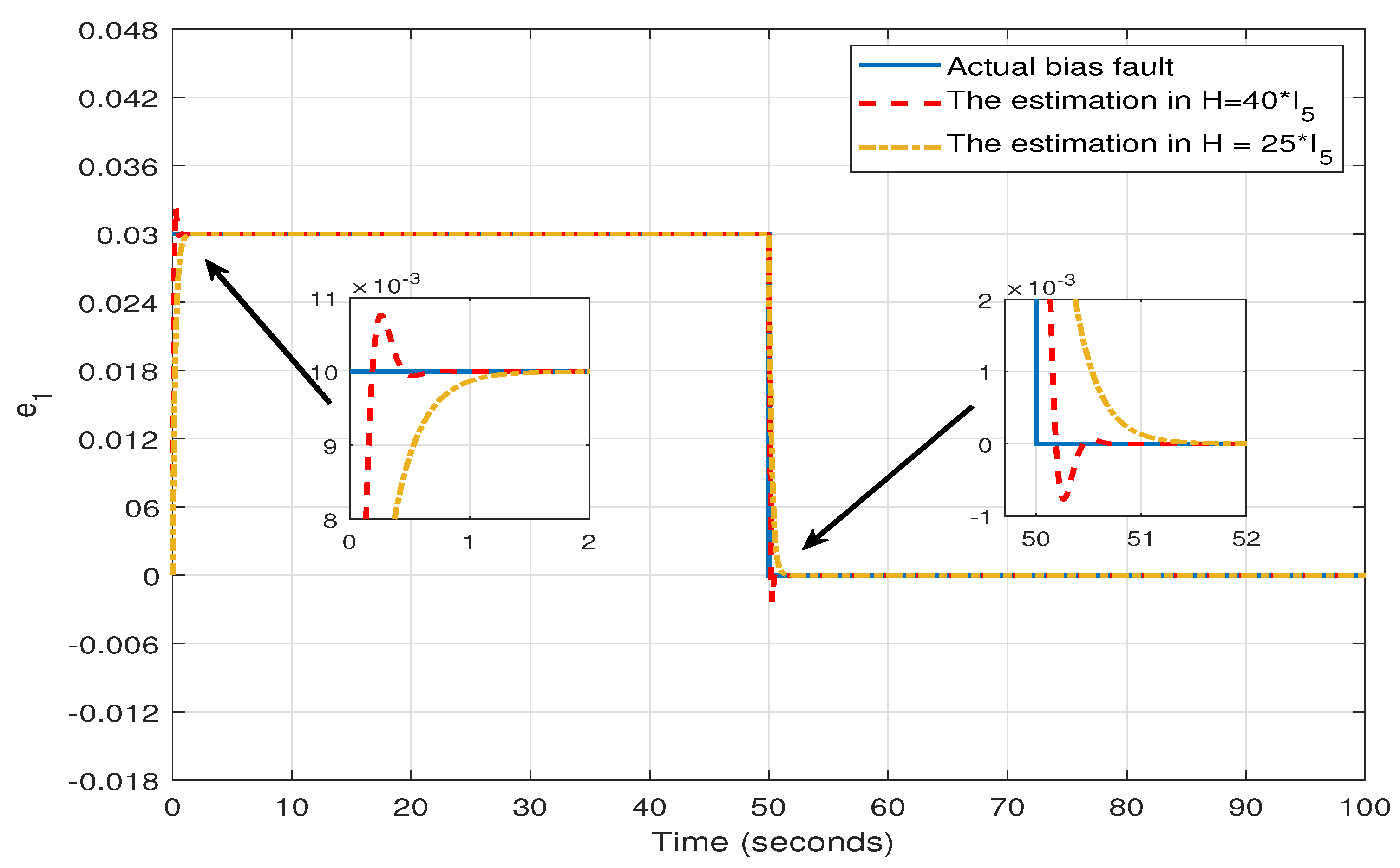
Among the observer parameters, the most important ones are H i and ρ i . Increasing H i can accelerate the lumped disturbance error variable d ˜ i to zero more quickly, but too large an H i value will also cause the overshoot of the error system. Increasing the ρ i can make the estimation value curve smooth but will enlarge the lumped disturbance error variable d ˜ i [31]. Hence, it requires many serious adjustments to obtain the better performance.

3.2. Fault-Tolerant Controller Design

To maneuver the frequency fluctuation problem of the multi-area interconnected power system with the impacts caused by lumped disturbances, a fault-tolerant control method based on an observer is developed to achieve the control objective lim t y i ( t ) = y d i ( t ) , and the tracking error is defined as e i ( t ) = y i ( t ) y d i ( t ) . The fractional integral terminal sliding function is defined as [33]
s i ( t ) = e i ( t ) + α i E i ( t ) ,
E ˙ i ( t ) = e i q i / p i ( t ) , with E i ( 0 ) = e i ( 0 ) / α i .
From the definition (23) and (24), the fractional integral terminal sliding function can be expressed in the form
s i ( t ) = e i ( t ) + α i 0 t e i q i / p i ( τ ) d τ , and s i ( 0 ) = 0 .
The time derivative of s i ( t ) can be written as
s ˙ i ( t ) = e ˙ i ( t ) + α i e i q i / p i ( t ) .
In this study, the reaching law is selected as the following exponential form
s ˙ i = k i s i ε i sgn s i ,
where k i > 0 and ε i > 0 are two positive real scalars, and from the Equations (26) and (27), the FTC can be designed as follows:
u c i = B i i 1 A i i x i B i i d ^ i h ij + C i 1 k i s i ε i sgn ( s i ) α i e i q i / p i ,
where α i > 0 ; p i and q i are odd integers satisfying p i > q i > 0 ; E i ( t ) = 0 t e i q i / p i ( τ ) d τ is the integration of the q i / p i -fractional power of the tracking error e i with the initial value e i ( 0 ) / α i . Because p i > q i > 0 , then e i q i / p i will not be equal to infinity, and the controller is nonsingular [34]. Based on the above analysis, the main result of this paper can be described as the following theorem.
Theorem 1.
For the multi-area interconnected power system (14) and (15), if Assumptions 1 and 2 are satisfied, then the fault-tolerant control proposed in (28) guarantees that the tracking error converges to zero.
Proof. 
In order to perform the stability analysis for the faulty systems under FTC (28), a Lyapunov function is chosen as
V i = 1 2 s i 2 .
Taking the time derivative of V, one has
V i ˙ = s i s i ˙ = s i e ˙ i + α e i q i / p i = s i C i ( A i i x i + B i i u c i + B i i d i + h ij ) + α e i q i / p i .
Substituting (28) into (30), the above equality is transformed into the following form
V i ˙ = s i C i B i i ( d d ^ ) + C 1 k i s i ε i sgn s i α i e i q i / p i + + α i e i q i / p i = s i C i B i i d i ˜ k i s i ε i sgn s i .
It is noted that d ˜ i ( t ) = d ^ i ( t ) d i ( t ) is the composite disturbances estimation error; by selecting the appropriate observer, the estimation error d i ˜ could asymptotically converge to zero. Meanwhile, ε i can be chosen accordingly such that the following inequality holds:
V ˙ i k i s 2 ε i s i < 0 .
According to the Lyapunov stability theory, it can be concluded that the tracking error e i converges to 0 as time goes to infinity. □
Remark 3.
Among the controller parameters, the most important ones are k i , ε i , and α i e i q i / p i . In the reaching law (27), the convergence rate depends on k i , which can ensure that when the sliding mode surface is too large, the state of the system can approach the sliding mode dynamics at a greater speed. The existence of ε i sgn ( s ) makes the convergence rate ε i , rather than zero, when s i is close to zero. Therefore, in order to ensure the fast convergence and reduce the chattering phenomenon, k i should be increased while ε i should be reduced. The convergent time of e i is related with α i e i q i / p i , as shown in [33].

4. Simulations

To validate the proposed control method, a four-area interconnected power system with HESS is considered in this section. The parameters of the observer and fault-tolerant controller are listed in Table 2. The parameters of the four-area interconnected power system are shown in Table 3 [13].
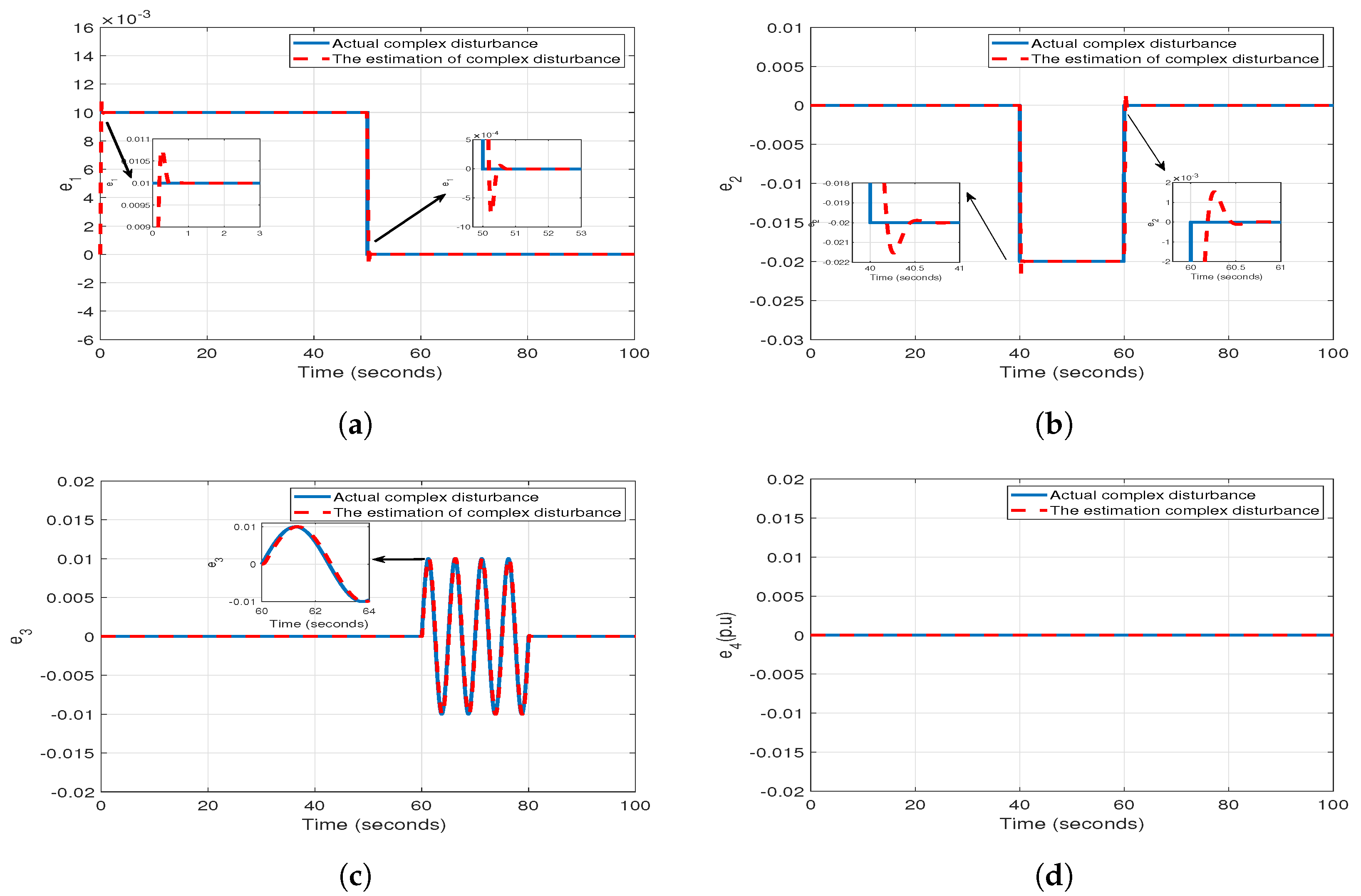
In order to test the effectiveness of the proposed observer, we consider that disturbances including the load fluctuations and the actuator faults occur in the four regions of the system. In Figure 5, the estimations of disturbances are shown, which yield satisfying performance. Meanwhile, it is noticed that the disturbances in a certain region can hardly affect the observers in other interconnected system due to the existence of the power tie-line connection. The comparison of the observer performance under different parameters is shown in Figure 6.
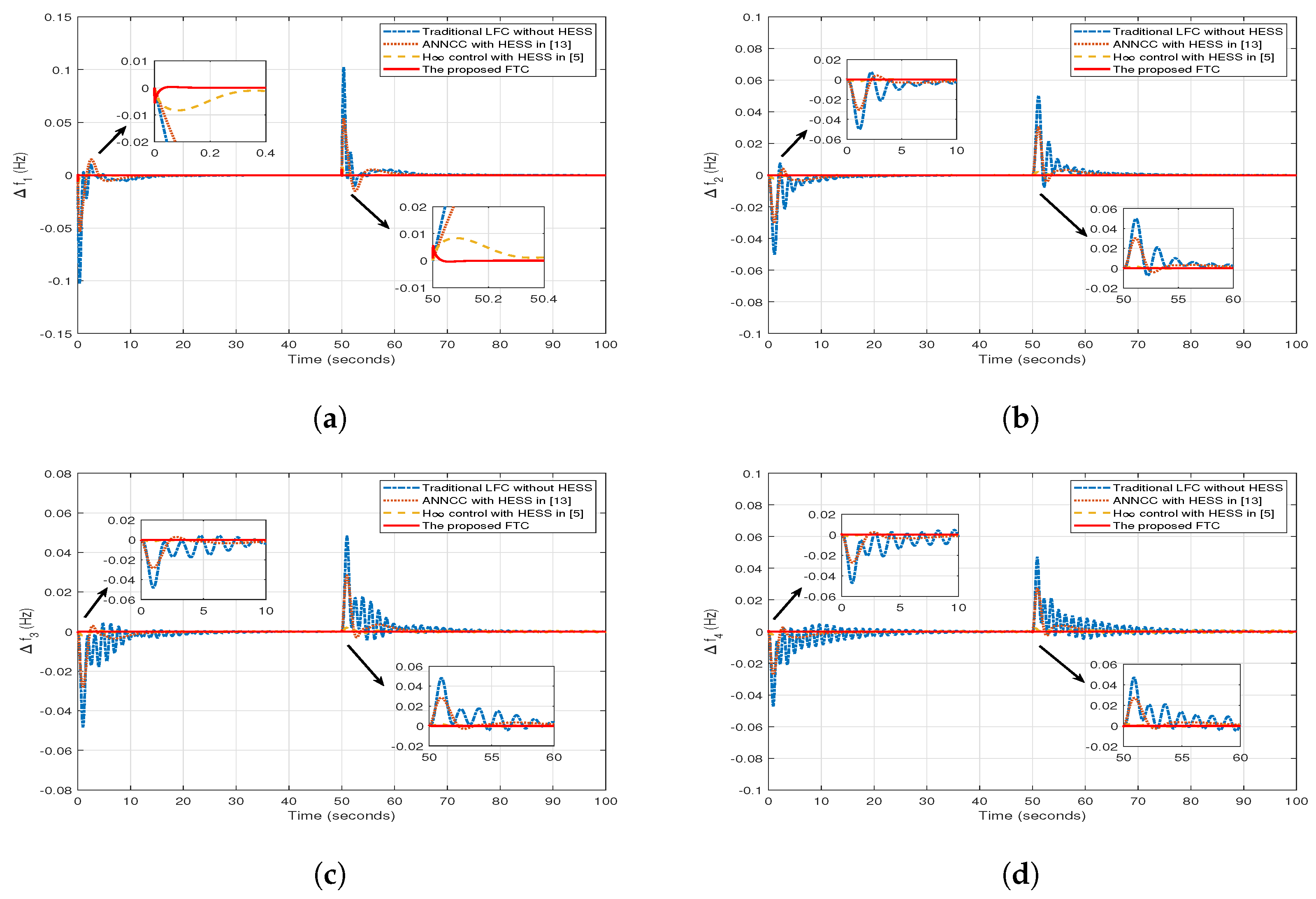
The control performance of the proposed approach is further investigated; the control system is subjected to a lumped disturbance of 0.02 p.u (1500 kW). Another 0.015 p.u (1125 kW) is considered at time 50 s. The resultant control performance is given in Figure 7 and Figure 8. It shows that the proposed controller can effectively improve the robustness and stability of the control system. Meanwhile, the four areas’ frequency deviations are below 0.01 Hz, and the output A C E i of the system are kept in a narrow range compared with the methods reported in [5,13], where the adaptive neural network constrained control (ANNCC) with HESS, in [13], and H∞ robust control with HESS, in [5] are studied.
According to the simulations, it is easy to see that the proposed approach outperforms the traditional controller without HESS, ANNCC with HESS, and H∞ control method with HESS. Moreover, the existence of HESS can effectively reduce the power oscillations.

5. Conclusions

In this paper, an observer-based sliding mode fault-tolerant controller is proposed by considering a slide-mode-based adaptive control strategy. In order to estimate the fault caused by external load disturbances and actuator faults, an observer is constructed. The stability of the whole system is analyzed by the Lyapunov theory. It is shown that the closed-loop stability of multi-area interconnected power systems can be guaranteed by the proposed approach. The simulations yield the effectiveness of the proposed control scheme by comparing with other control methods. In addition, the establishment of a non-linear model of the interconnected power system and considering the system uncertainty, a more comprehensive actuator fault modeling could improve the technical and economical performance of the power system.
In multi-area power systems, data delay and packet loss problems are inevitable for long-distance data transmissions. Moreover, they is also susceptible to network attacks where wrong data/information are injected [35]. In our future work, we will improve our proposed FTC scheme by considering the system uncertainties and coupled sensor faults with time delays, which may extend the current results to more general cases.

Author Contributions

Conceptualization, W.Y., D.Y. and D.X.; methodology, W.Y., D.Y. and D.X.; formal analysis, D.Y., Y.Z.; investigation, D.Y., Y.Z.; data curation, D.Y.; writing—original draft preparation, D.Y.; writing—review and editing, D.Y.; project administration, W.Y., D.X.; funding acquisition, D.X., W.Y.

Funding

This work was partially supported by the National Natural Science Foundation of China (61490703), National first-class discipline program of Food Science and Technology (JUFSTR20180205), Fundamental Research Funds for the Central Universities (JUSRP41911), and the National Science Foundation of Jiangsu Province of China (BK20180595).

Conflicts of Interest

The authors declare no conflict of interest.

Appendix A

The space-state matrices of the multi-area power system model defined in Equation (11) are detailed here. The closed-loop system is defined by the following matrices
A i i = 1 T P i K P i T P i 0 0 K P i T P i 0 1 T T i 1 T T i 0 0 ( 1 R i + K A F i ) T G i 0 1 T G i 1 T G i 0 B i R i 0 0 0 1 2 π j = 1 , i j n T i j 0 0 0 0 , B i i = K P i T P i 0 0 0 0 , C i = β i R i 0 0 0 1 T
A i j = 0 0 0 0 0 0 0 0 0 0 0 0 0 0 0 0 0 0 0 0 2 π T i j 0 0 0 0 , B i j = 0 0 0 0 0 .

References

  1. Dong, L.; Tang, Y.; He, H.; Sun, C. An event-triggered approach for load frequency control with supplementary ADP. IEEE Trans. Power Syst. 2017, 32, 581–589. [Google Scholar] [CrossRef]
  2. Singh, V.P.; Kishor, N.; Samuel, P. Load frequency control with communication topology changes in smart grid. IEEE Trans. Ind. Inform. 2016, 12, 1943–1952. [Google Scholar] [CrossRef]
  3. Liu, X.; Kong, X.; Lee, K.Y. Distributed model predictive control for load frequency control with dynamic fuzzy valve position modelling for hydro–thermal power system. IET Control Theory Appl. 2016, 10, 1653–1664. [Google Scholar] [CrossRef]
  4. Liu, F.; Li, Y.; Cao, Y.; She, J.; Wu, M. A two-layer active disturbance rejection controller design for load frequency control of interconnected power system. IEEE Trans. Power Syst. 2016, 31, 3320–3321. [Google Scholar] [CrossRef]
  5. Yan, W.; Sheng, L.; Xu, D.; Yang, W.; Liu, Q. H∞ Robust Load Frequency Control for Multi-Area Interconnected Power System with Hybrid Energy Storage System. Appl. Sci. 2018, 8, 1748. [Google Scholar] [CrossRef]
  6. Sabahi, K.; Sharifi, A.; Sh, M.A.; Teshnehlab, M.; Alisghary, M. Load frequency control in interconnected power system using multi-objective PID controller. J. Appl. Sci. 2008, 8, 3676–3682. [Google Scholar] [CrossRef]
  7. Rubaai, A.; Udo, V. An adaptive control scheme for load-frequency control of multiarea power systems Part I. Identification and functional design. Electr. Power Syst. Res. 1992, 24, 183–188. [Google Scholar] [CrossRef]
  8. Rahmani, M.; Sadati, N. Hierarchical optimal robust load-frequency control for power systems. IET Gener. Transm. Distrib. 2012, 6, 303–312. [Google Scholar] [CrossRef]
  9. Mi, Y.; Fu, Y.; Wang, C.; Wang, P. Decentralized sliding mode load frequency control for multi-area power systems. IEEE Trans. Power Syst. 2013, 28, 4301–4309. [Google Scholar] [CrossRef]
  10. Ersdal, A.M.; Cecílio, I.M.; Fabozzi, D.; Imsland, L.; Thornhill, N.F. Applying Model Predictive Control to Power System Frequency Control; IEEE PES ISGT Europe 2013; IEEE: Piscataway, NJ, USA, 2013; pp. 1–5. [Google Scholar]
  11. Qian, D.; Zhao, D.; Yi, J.; Liu, X. Neural sliding-mode load frequency controller design of power systems. Neural Comput. Appl. 2013, 22, 279–286. [Google Scholar] [CrossRef]
  12. ud din Mufti, M.; Lone, S.A.; Iqbal, S.J.; Ahmad, M.; Ismail, M. Super-capacitor based energy storage system for improved load frequency control. Electr. Power Syst. Res. 2009, 79, 226–233. [Google Scholar] [CrossRef]
  13. Xu, D.; Liu, J.; Yan, X.; Yan, W. A novel adaptive neural network constrained control for a multi-area interconnected power system with hybrid energy storage. IEEE Trans. Ind. Electron. 2018, 65, 6625–6634. [Google Scholar] [CrossRef]
  14. Mufti, M.D.; Iqbal, S.J.; Lone, S.A.; Ain, Q.U. Supervisory Adaptive Predictive Control Scheme for Supercapacitor Energy Storage System. IEEE Syst. J. 2014, 9, 1020–1030. [Google Scholar] [CrossRef]
  15. Shankar, R.; Chatterjee, K.; Bhushan, R. Impact of energy storage system on load frequency control for diverse sources of interconnected power system in deregulated power environment. Int. J. Electr. Power Energy Syst. 2016, 79, 11–26. [Google Scholar] [CrossRef]
  16. Shankar, R.; Bhushan, R.; Chatterjee, K. Small-signal stability analysis for two-area interconnected power system with load frequency controller in coordination with FACTS and energy storage device. Ain Shams Eng. J. 2016, 7, 603–612. [Google Scholar] [CrossRef] [Green Version]
  17. Molina, M.; Mercado, P. Modeling of a DSTATCOM with ultra-capacitor energy storage for power distribution system applications. In Proceedings of the 13th Eriac Decimo Tercer Encuentro Regional Iberoamericano De Cigre, Foz de Iguazu, Argentina, 24–28 May 2009; pp. 1–8. [Google Scholar]
  18. Attya, A.B.T.; Hartkopf, T. Utilising stored wind energy by hydro-pumped storage to provide frequency support at high levels of wind energy penetration. IET Gener. Transm. Distrib. 2015, 9, 1485–1497. [Google Scholar] [CrossRef]
  19. Gurumurthy, S.R.; Agarwal, V.; Sharma, A. High-efficiency bidirectional converter for flywheel energy storage application. IEEE Trans. Ind. Electron. 2016, 63, 5477–5487. [Google Scholar] [CrossRef]
  20. Bruno, S.; Dellino, G.; La Scala, M.; Meloni, C. A Microforecasting Module for Energy Management in Residential and Tertiary Buildings. Energies 2019, 12, 1006. [Google Scholar] [CrossRef]
  21. Liu, M.; Ho, D.W.; Shi, P. Adaptive fault-tolerant compensation control for Markovian jump systems with mismatched external disturbance. Automatica 2015, 58, 5–14. [Google Scholar] [CrossRef]
  22. Khalili, M.; Zhang, X.; Polycarpou, M.M.; Parisini, T.; Cao, Y. Distributed adaptive fault-tolerant control of uncertain multi-agent systems. Automatica 2018, 87, 142–151. [Google Scholar] [CrossRef] [Green Version]
  23. Yang, H.; Jiang, B.; Staroswiecki, M.; Zhang, Y. Fault recoverability and fault tolerant control for a class of interconnected nonlinear systems. Automatica 2015, 54, 49–55. [Google Scholar] [CrossRef]
  24. Liu, X.; Gao, Z.; Zhang, A. Observer-based fault estimation and tolerant control for stochastic Takagi–Sugeno fuzzy systems with Brownian parameter perturbations. Automatica 2019, 102, 137–149. [Google Scholar] [CrossRef]
  25. Panagi, P.; Polycarpou, M.M. Distributed fault accommodation for a class of interconnected nonlinear systems with partial communication. IEEE Trans. Autom. Control 2011, 56, 2962–2967. [Google Scholar] [CrossRef]
  26. Polycarpou, M.M.; Panagi, P. A coordinated communication scheme for distributed fault tolerant control. IEEE Trans. Ind. Inform. 2013, 9, 386–393. [Google Scholar]
  27. Jin, X.; Yang, G. Distributed adaptive robust tracking and model matching control with actuator faults and interconnection failures. Int. J. Control. Autom. Syst. 2009, 7, 702. [Google Scholar] [CrossRef]
  28. Tong, S.; Huo, B.; Li, Y. Observer-based adaptive decentralized fuzzy fault-tolerant control of nonlinear large-scale systems with actuator failures. IEEE Trans. Fuzzy Syst. 2014, 22, 1–15. [Google Scholar] [CrossRef]
  29. Liu, T.; Hill, D.J.; Jiang, Z. Lyapunov formulation of ISS cyclic-small-gain in continuous-time dynamical networks. Automatica 2011, 47, 2088–2093. [Google Scholar] [CrossRef]
  30. Ibraheem; Kumar, P.; Kothari, D.P. Recent philosophies of automatic generation control strategies in power systems. IEEE Trans. Power Syst. 2005, 20, 346–357. [Google Scholar] [CrossRef]
  31. Gao, Z.; Jiang, B.; Shi, P.; Qian, M.; Lin, J. Active fault tolerant control design for reusable launch vehicle using adaptive sliding mode technique. J. Frankl. Inst. 2012, 349, 1543–1560. [Google Scholar] [CrossRef]
  32. Efimov, D.; Edwards, C.; Zolghadri, A. Enhancement of adaptive observer robustness applying sliding mode techniques. Automatica 2016, 72, 53–56. [Google Scholar] [CrossRef] [Green Version]
  33. Chiu, C.S. Derivative and integral terminal sliding mode control for a class of MIMO nonlinear systems. Automatica 2012, 48, 316–326. [Google Scholar] [CrossRef]
  34. Song, H.; Zhang, T. Fast robust integrated guidance and control design of interceptors. IEEE Trans. Control Syst. Technol. 2015, 24, 349–356. [Google Scholar] [CrossRef]
  35. Wang, X.; Luo, X.; Zhang, M.; Guan, X. Distributed detection and isolation of false data injection attacks in smart grids via nonlinear unknown input observers. Int. J. Electr. Power Energy Syst. 2019, 110, 208–222. [Google Scholar] [CrossRef]
Figure 1. Schematic of a multi-area interconnected power system with a hybrid energy storage system (HESS), where “G” represents the generator system, “L” represents the load, and “H” represents the HESS.
Energies 12 02819 g001
Figure 2. The transfer function model of the i-th area of the interconnected power system, where G g i represents the transfer function model of the governor, G t i represents the transfer function model of the steam turbine, and G p i represents the transfer function model of the generator.
Energies 12 02819 g002
Figure 3. The basic structure of the HESS.
Energies 12 02819 g003
Figure 4. The schematic diagram of the proposed FTC design for the multi-area power system.
Energies 12 02819 g004
Figure 5. The four areas’ actual lumped disturbances and their estimation: (a) a lumped disturbance increment of 0.01 p.u followed by a lumped disturbance rejection of 0.01 p.u; (b) a lumped disturbance rejection of 0.02 p.u followed by a lumped disturbance increment of 0.02 p.u; (c) a sinusoidal lumped disturbance; (d) non-disturbance.
Energies 12 02819 g005
Figure 6. The comparisons of observer performance under different parameters.
Energies 12 02819 g006
Figure 7. The A C E i ( i = 1 , 2 , 3 , 4 ) of each area subjected to a lumped disturbance of 0.02 p.u and another 0.015 p.u at time 50 s, followed by comparison with the methods reported in [5,13]: (a) A C E 1 ; (b) A C E 2 ; (c) A C E 3 ; (d) A C E 4 . ANNCC—adaptive neural network constrained control.
Energies 12 02819 g007
Figure 8. The frequency deviation of a four-area interconnected power system subjected to a lumped disturbance 0.02 p.u and another 0.015 p.u at time 50 s: (a) Δ f 1 ; (b) Δ f 2 ; (c) Δ f 3 ; (d) Δ f 4 .
Energies 12 02819 g008
Table 1. Nomenclature used in the paper.
ParametersDescription
T i j Tie-line power synchronization coefficient
T p i Time constant of power system
T g i Time constant of governor
T t i Time constant of turbine
K i 1.00,0.00,0.00Control gain of PI controller in area i
Δ P d i Load disturbance
Δ P t i e i Tie-line deviation of power exchange between area i and others
Δ X e i Incremental variation of governor valve positon
Δ P c i Power delivered by the HESS to area i
K p i Power system gain
Δ f i Load frequency deviation of power system
β i Set value of frequency deviation
A C E i Control error of the i-th area.
R i Speed regulation gain
K A F i Proportional feedback coefficient of frequency deviation
diag { } A diagonal matrix
· The euclidean norm
I n N-dimensional unit matrix
HESSHybrid energy storage system
LFCLoad frequency control
FTCFault-tolerant control
SMCSliding model control
ACEArea control error
Table 2. Parameters used in the proposed method in a four-area interconnected power system.
ParametersValues
Observer parameters γ = 1
H 1 = 40 I 5 H 2 = 40 I 5 H 3 = 40 I 5 H 4 = 40 I 5
ρ 1 = 80 ρ 2 = 80 ρ 3 = 80 ρ 4 = 80
Controller parameters p 1 = 5 p 2 = 5 p 3 = 5 p 4 = 5
q 1 = 3 q 2 = 3 q 3 = 3 q 4 = 3
k 1 = 12 k 2 = 12 k 3 = 12 k 4 = 12
α 1 = 15 α 2 = 15 α 3 = 15 α 4 = 15
ε 1 = 0.01 ε 2 = 0.01 ε 3 = 0.01 ε 4 = 0 . 01
Table 3. The parameters of the four-area interconnected power system.
Area i T gi (s) T ti (s) R i (Hz/p.u.Mw) T ij (s) K pi (Hz/p.u.Mw) T pi (s) β i (Hz/p.u.Mw) K AFi
10.080.32.40.0707120200.4251.1
20.0720.332.70.0707112.5250.4251.1
30.070.352.50.0707125200.4251.1
40.0850.37520.0707115150.4251.1