1. Introduction
Unlike in conventional passenger vehicle tyres, the sudden release of pressurized gas in large tyres installed on trucks, tractor-trailers and earth-moving or off-highway vehicles may cause the separation of tyre parts, which will be projected away with considerable speed and force. An explosion is a rapid increase in volume and an energy release, and is usually accompanied by the generation of high temperatures, pressure, radiation emission (e.g., sparks) and acoustic waves. Explosions occur due to rapid exothermic chemical reactions (e.g., combustion), runaway chain reactions and rapid physical phenomena (e.g., steam boiler and gas pressure vessel explosions) [
1,
2].
Threats of mechanical origin may arise due to emergency situations, i.e., tyre damage incurred during inflation, or an unpredicted sliding of the tyre securing ring. Improper handling and assembly of the tyre, rim, or wheel can cause the tyre components to explode [
3,
4]. According to the literature [
4], four mechanical incidents may cause a tyre to burst: Over-inflation, zipper failure, tyre removal and poor tyre condition or structural defects. These observations are supported by several studies [
3,
5,
6].
Explosive hazards are also present if an operator attempts to install a tyre on an incorrect diameter rim, or to inflate or service a tyre that is already mounted on an incorrect rim. Such explosions may result in severe injuries or even death [
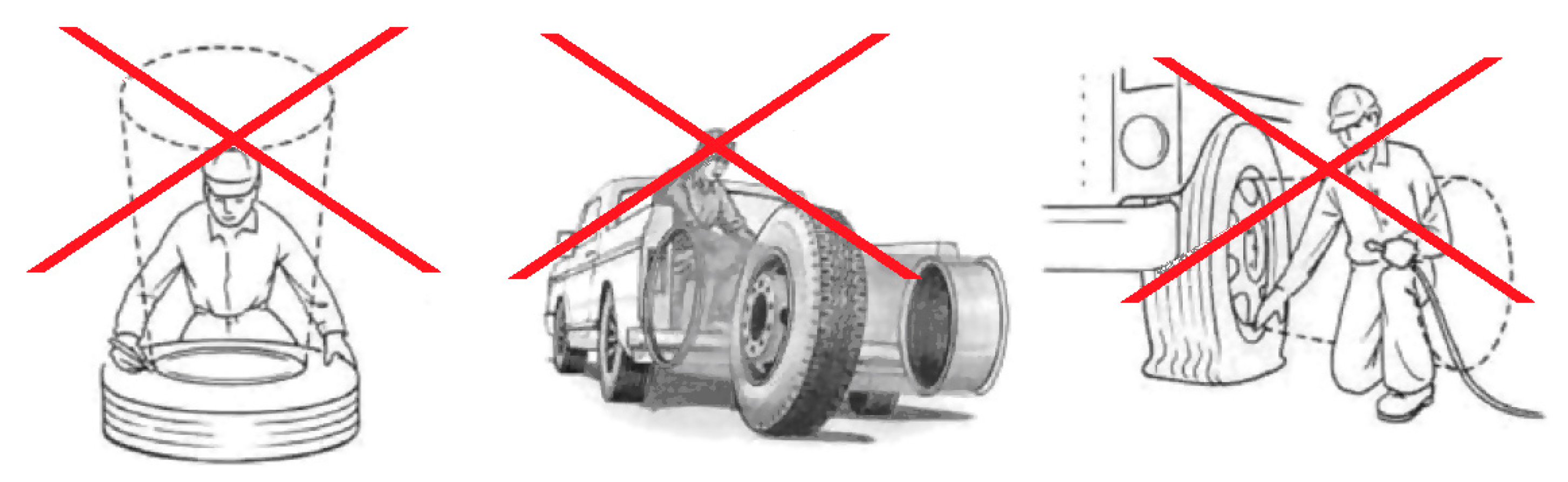
6]. To avoid all risks of accidents and injuries during tyre inflation, the following precautions must be taken [
4]:
Place the wheel in a safety cage.
Always use a clip-on air chuck with an air hose extension, equipped with a control valve and a pressure gauge.
Maintain a safe distance (approximately 2 m) between the worker and the tyre to be inflated. The operator should never stand facing the wheel, but instead stand to the side, facing the tread (
Figure 1).
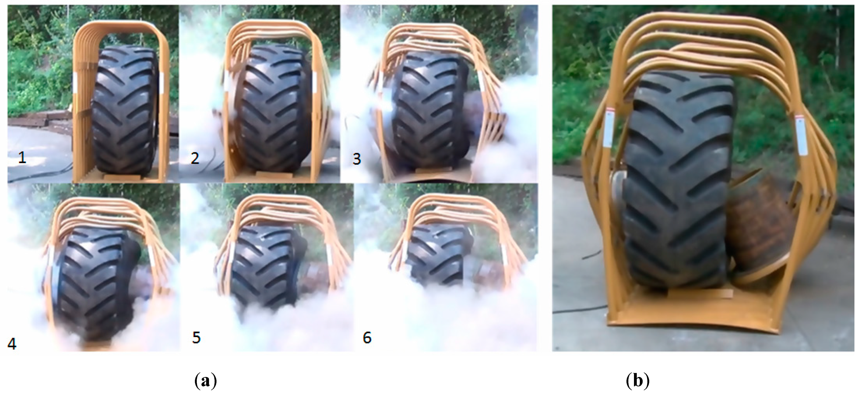
In order to visualize the operator risk,
Figure 2 shows the sequence of events which occurred during a controlled tyre explosion that was tested in one of the largest available safety cages.
The safety cage was manufactured by Ken-Tool and was 1.22 m (48”) wide, 1.83 m (72”) long, and 2.29 m (90”) high. Testing was performed on a 29.5R25 L-3 Earthmover tyre with dimensions of 0.84 m (33”) width and 1.78 m (70”) height. The weight of the tyre and the three-piece steel wheel was 703 kg (1550 lbs), and the burst pressure was 1.034 MPa (150 PSI).
A similar blast resulted in an operator’s death. To reconstruct the fatal accident, a numerical analysis of a tyre burst was performed using multibody and finite element methods. The finite element (FE) model used in the simulations was based upon the actual geometry of tyres found in the literature, mainly for safety assessment [
8,
9,
10,
11] and traction properties [
12,
13]. Furthermore, the virtual multibody dummy model was coupled with previously-published FE codes to verify the sustained injury levels [
14,
15].
In
Figure 3, the example safety cage manufactured by RLM Distributing is shown beside a computer-aided 3D model created by the authors for the LENA Wilkow company.
This publication focuses on a case in which a safety cage was not used, and the overinflation of a large tyre to 1.1 MPa can lead to fatal head injuries [
17,
18].
2. Methods
The goal of testing was to determine the possible trajectories and velocities for failures occurring at different tyre pressures.
The scope of the work included:
Developing a geometric model of the wheel’s rim and tyre (simplified models with mass parameters corresponding to an actual tyre and rim).
Development of a tyre-specific calculation model.
Analysis of the motion of a damaged tyre for pressures between 0.6 and 1.1 MPa.
Analysis of the results and the formulation of conclusions.
The authors simulated a situation using two numerical simulation packages coupled together: LS-DYNA (Livermore Software Technology Corporation, Livermore, CA, USA) and MADYMO (TASS International Software and Services, Helmond, the Netherlands). These were used to provide evidence for the use of safety cages to protect operators during an uncontrolled tyre blast [
19]. The analysis results may be used to guide the selection of strong and relatively light replacement materials for safety cages [
20,
21,
22,
23,
24].
2.1. Visual Inspection of the Tyre
Prior to the construction of the numerical model, the tyre was visually inspected in order to quantify its geometric parameters. Additionally, both the size and nature of the damage were assessed to determine the size of the surface over which there was an uncontrolled outflow of air. The examined tyre model was 29.5 R25 (the nominal section width of the tyre was 29.5”, and the rim diameter was 25”; radial construction) with some reinforcements for mining purposes. The tyre was removed from an underground machine—similar to the one depicted in
Figure 4—for inflation. The outflow was identified between the ring and the tyre tangential to the tyre’s side surface from a rupture that was approximately 92 cm (36.22”) in length. Hence, taking into account the length of the side of the main outflow surface, the tangent to the tyre flow was located along the edges with a length of about 72 cm (28.35”).
Figure 5 depicts the examination of the tyre, and shows the “streak” resulting from condensation due to air expansion. The main area of flow is marked with a blue arrow, and the red dashed arrow shows where the flow was tangential to the tyre surface.
The main outflow area had a trapezoidal shape whose dimensions are depicted in
Figure 6. The area of the outflow is important for further analytical and numerical calculations.
Moreover, air was released between the ring and the tyre tangentially to the tyre surface, and the total length of the burst was about 920 mm (36.22”). Hence, taking into account the length of the side of the main outflow area, the outflow that was tangential to the tyre occurred along an edge with an approximate length of 720 mm (28.35”).
2.2. Finite Element Model of Tyre
A finite element (FE) model was developed based on a simplified geometric model of the wheel and the tyre [
25,
26]. A geometric model of the tyre was created using professional 3D design software Catia V5 (Dassault Systèmes, Vélizy-Villacoublay, France) and is shown in
Figure 7,
Figure 8,
Figure 9 and
Figure 10.
The parameters of the constructed model listed in
Table 1 include geometric parameters, mass, moments of inertia about the centre of gravity parallel to the global Cartesian coordinate system, and selected principal moments, in accordance with
Figure 5. The mass of the tyre model was 840 kg (1851.88 lbs—with rubber reinforcements), whereas the mass of the rim and securing rings was 262 kg (577.6 lbs).
The finite element (FE) model is presented in
Figure 11.
To model the wheel and tyre, solid finite elements with three degrees of freedom in the node were used. The entire model contained 62,560 hexa-elements supported on 65,840 nodes.
2.3. Analytical Calculations
In the case of gas outflow from the tank through a hole or short nozzle from an area of high pressure to an area of lower pressure (the atmosphere), this process was assumed to be adiabatic (
Figure 12).
In this case, the flow speed can be calculated from Bernoulli’s equation [
27,
28], assuming V1 = 0 (gas velocity in a tank), hence:
where
κ is the adiabatic exponent (1.41 for 20 °C air),
p is the pressure (before
p1; after
p2),
ρ is the density (before
ρ1; after
ρ2), and
v is the velocity (before
v1 = 0; after
v2).
After some formula transformations, knowing that F2 is the section of the gap (outlet) in the tyre, , so thus .
Thus, the outlet velocity
v2 and mass flow rate of gas
Qm can be calculated as follows:
Loads acting upon the tyre during air flow due to cracks were analytically calculated. The sudden outflow of gas from the tyre can be considered an adiabatic transformation, because no heat transfer occurs between the air in the tyre (the tank) and the environment. Therefore, all of the stored energy in the tyre is used to perform the work needed to lift and move the tyre. In accordance with the Clapeyron Gas Law the energy stored in the pressurized tyre was calculated to be 1.1033 MJ.
Assuming the volume of air in the tyre did not change with pressure, and based upon the constructed geometric model of the tyre and rim, the volume of air in the tyre was determined to be 1.003 m
3 [
29]. However, according to the data available from the tyre manufacturer, the tyre volume was 0.988 m
3, but the manufacturer did not specify the influence of the shape of the wheel rims on the air volume. Thus, it is possible that the volume measured in the tyre was measured, and that the modelled volume agreed with the manufacturer’s data.
2.4. Numerical Calculations of the Damaged Tyre
The mathematical model presented in the previous section was then applied to the analysed wheel, and calculations were performed for pressures ranging from 0.6 MPa to 1.1 MPa in 0.05 MPa increments.
Figure 13 shows the relationship between the total air release time from the tyre and the initial tyre pressure.
The recorded time was the time necessary for the air outlet velocity to drop to zero, i.e., for the pressure inside the tyre to equalise with the atmospheric pressure. Higher initial pressures required longer times for the air to flow out.
Figure 14 and
Figure 15 show the changes in the basic parameters characterizing the release of air from the tyre (the “lifting” force and the release velocity) for the main release surface at an initial pressure of 1.1 MPa. The force was defined as a curve in the LS-DYNA explicit code, and the force vector was normal to the plane of the damaged part of the tyre at all times.
The change in force at an initial tyre pressure of 1.1 MPa is shown in
Figure 14. The force decreased due to a lower mass stream in the outgoing air, which occurred due to a pressure drop and a lower air density inside the tyre. So, for a given time (ca. 700 ms for an initial pressure of 1.1 MPa), the outflow occurred at a constant speed, equal to the critical speed of the simultaneously decreasing mass flow, due to the drop in air density inside the tyre. This affected the magnitude forces acting upon the unsealed tyre (
Figure 14).
During the initial phase, the outflow of air from the tyre occurred at a critical speed equal to the speed of sound in the environment in which the outflow occurred (
Figure 15). It was assumed in the analysis that the speed of sound in air at 20 °C was equal to 343.8 m/s (1127.95 feet per second, or 769 mph). The trajectory of the damaged tyre was obtained through calculations, and
Figure 16 depicts the trace of a point located next to the tyre’s outflow.
The damaged tyre bounced on the ground, yet did not hit the modelled celling (reconstructed conditions). The entire tyre motion lasted approximately 4000 ms, and the force magnitude was null after 1000 ms, as presented in
Figure 14. The tyre motion was caused by the residual kinetic energy and elastic properties of the tyre.
2.5. Analysis and Discussion of Operator Injury
The next step in the numerical calculations was to add an operator (a male MADYMO dummy) to the simulations to reflect a fatal accident during tyre pumping. In a real case, an operator was determined to have incurred traumatic brain injury (TBI) and internal injuries [
30,
31,
32], but the exact details of the accident have not been disclosed, since it is an ongoing investigation. However, the authors obtained the standard inflation procedure, and also some information from witnesses, which allowed a full coupling analysis to be calculated which included the operator and the exploding tyre [
33]. Hence, the MADYMO multibody code with its validated 50
th male dummy was coupled with LS-DYNA explicit code to simulate the tyre explosion. Numerical multibody joints were adjusted to reflect the operator’s leaning position during tyre inflation (
Figure 17). A coupling contact was added between the tyre and operator, and the time step and units were accordingly adjusted to meet the coupling requirements.
A graphical representation of the results of selected time frames is depicted in
Figure 18. It can be seen that during 150–250 ms, the operator was struck with the exploding tyre and violently pushed away. In the real case, post-mortem examination revealed that this resulted in severe head injuries and internal injuries.
To measure the likelihood of a head injury due to an impact, the Head Injury Criterion (HIC) was used:
where
a(t) is the resultant acceleration measured in g (standard gravity acceleration),
t1 and
t2 are the initial and final times (in seconds) chosen to maximize the HIC value, and the time duration,
t2 −
t1, was limited to a maximum value of 36 ms for HIC(36).
HIC includes the effects of head acceleration and the duration of the acceleration. High accelerations can be tolerated for very short times, and the severity of injuries is assessed by the Abbreviated Injury Scale (AIS) [
34]. This scale assesses the tissue damage and threat to life on a six-division ordinal scale, running from minor (AIS 1) through moderate (AIS 2), serious (AIS 3), severe (AIS 4), critical (AIS 5), to generally unsurvivable/ usually fatal (AIS 6) [
35]. One of the estimated relations between HIC(36) and the probability of skull fracture is presented in
Figure 19.
To verify HIC(36) and evaluate the operator’s fatal head injuries, head acceleration was plotted in MADYMO code and then used to calculate HIC(36). The acceleration run was filtered with the CFC 1000 filter, and an HIC(36) value near 3000 (
Figure 20) was obtained for the tyre strike.
Due to computational time, the ground hit was not taken into consideration, and such information is generally less important due many other variables influencing the operator’s kinematics. Basing on a literature review, the probability of death was close to 100% [
37,
38,
39,
40,
41,
42]. Consequently, it was unambiguously shown that improper tyre inflation, especially in larger vehicles, may lead to fatal injuries.
3. Conclusions
Inflated tyres of large trucks and off-highway vehicles contain tremendous amounts of energy due to their high pressures. Tyre inflation is an important performance and safety factor, and although they are relatively rare, tyre failures may be very dangerous. An example of tyre failure is over-pressurization, which may occur during the inflation or separation of the tyre lock ring due to rim damage. In this paper, an example was presented in which the tyre of an underground machine burst during inflation. Knowledge of the boundary conditions of the accident and through analytical calculations, it was possible to carry out simulations which included an operator.
The numerical model represented a damaged tyre over-inflated to 1.1 MPa, which had a stored energy of approximately 1.1 MJ. The HIC(36) value was computed to be ~3,000 using LS-DYNA and MADYMO analysis, and confirmed that the operator’s death was caused by head trauma. Therefore, a tyre must be inspected for side-wall cracks, distortions, wrinkles, discoloration and recent repairs performed prior to inflation. Additionally, the use of a safety cage is highly recommended, since they reduce the likelihood of any injuries which might occur during tyre inflation. However, the structure of the safety cage should be examined and tested before it is commercially utilised.
Future research will focus upon the development of new cages, e.g., those using new composite construction materials and designs. The ultimate ambition of the authors is to contribute to the development of standards regarding the safe operation of tyres.
Author Contributions
Conceptualization, J.K. and M.P.; methodology, J.K., M.P. and L.C.; software, J.K. and M.P.; validation, J.K., M.P. and L.C.; formal analysis, J.K., M.P. and L.C.; investigation, J.K., M.P. and L.C.; resources, J.K., M.P., L.C.; data curation, J.K. and M.P.; writing—original draft preparation, J.K., M.P. and L.C.; writing—review and editing, J.K., M.P. and L.C.; visualization, J.K., M.P. and L.C.; supervision, J.K., M.P. and L.C.; project administration, J.K., M.P. and L.C.; funding acquisition, L.C.
Funding
The publication was developed as part of project “Analysis of the tyre 29,5 R25 X after its failure” (Wroclaw University of Science and Technology, report 74/2011) as well as the project LIDER/8/0051/L-8/16/NCBR/2017 funded by the National Centre for Research and Development, Poland, and Grant 1/S/IESO/17 (commenced at the Maritime University of Szczecin).
Acknowledgments
Support given by the National Centre for Research and Development of Poland and Ministry of Science and Higher Education of Poland.
Conflicts of Interest
The authors declare no conflict of interest.
References
- Chybowski, L.; Kazienko, D. The Development of an Explosion Protection System in the Starting Air Manifold of a High Power Engine. Syst. Saf. Hum. Tech. Facil. Environ. 2019, 1, 26–34. [Google Scholar] [CrossRef] [Green Version]
- Chybowski, L.; Grządziel, Z.; Gawdzińska, K. Simulation and Experimental Studies of a Multi-Tubular Floating Sea Wave Damper. Energies 2018, 11, 1012. [Google Scholar] [CrossRef]
- Hefny, A.F.; Eid, H.O.; Abu-Zidan, F.M. Severe tyre blast injuries during servicing. Injury 2009, 40, 484–487. [Google Scholar] [CrossRef] [PubMed]
- Benoit, R. Heavy Vehicles Tire Blowout and Explosion; IRSST: Montreal, QC, Canada, 2009. [Google Scholar]
- Murty, O.P. Tyre-blast injuries. J. Forensic Leg. Med. 2009, 16, 224–227. [Google Scholar] [CrossRef] [PubMed]
- Bahn, S. Workplace hazard identification and management: The case of an underground mining operation. Saf. Sci. 2013, 57, 129–137. [Google Scholar] [CrossRef]
- Ken-Tool. Earthmover Tire Cage Test 8/23/2012; Ken-Tool: Akron, OH, USA, 2012. [Google Scholar]
- Baranowski, P.; Bogusz, P.; Gotowicki, P.; Małachowski, J. Assessment of Mechanical Properties of Offroad Vehicle Tire: Coupons Testing and FE Model Development. Acta Mech. Autom. 2012, 6, 17–22. [Google Scholar]
- Baranowski, P.; Malachowski, J.; Janiszewski, J.; Wekezer, J. Detailed tyre FE modelling with multistage validation for dynamic analysis. Mater. Des. 2016, 96, 68–79. [Google Scholar] [CrossRef]
- Yao, S.L.; Yue, Z.F.; Geng, X.L.; Wang, P.Y. Finite element analysis of aircraft tire for safety assessment with CV and CPM methods. Multidiscip. Model. Mater. Struct. 2017, 13, 501–518. [Google Scholar] [CrossRef]
- Baranowski, P.; Malachowski, J. Numerical study of selected military vehicle chassis subjected to blast loading in terms of tire strength improving. Bull. Polish Acad. Sci. Tech. Sci. 2015, 63, 867–878. [Google Scholar] [CrossRef] [Green Version]
- Xia, K. Use of explicit finite-element formulation to predict/terrain interaction: Application to predicting soil compaction and tire mobility. J. Terramech. 2011, 48, 113–123. [Google Scholar] [CrossRef]
- Rubinstein, D.; Shmulevich, I.; Frenckel, N. Use of explicit finite-element formulation to predict the rolling radius and slip of an agricultural tire during travel over loose soil. J. Terramech. 2018, 80, 1–9. [Google Scholar] [CrossRef]
- Ptak, M. Method to Assess and Enhance Vulnerable Road User Safety during Impact Loading. Appl. Sci. 2019, 9, 1000. [Google Scholar] [CrossRef]
- Fernandes, F.A.O.; Alves de Sousa, R.J.; Ptak, M. SpringerBriefs in Applied Sciences and Technology. In Head Injury Simulation in Road Traffic Accidents; Springer International Publishing: Cham, Switzerland, 2018; ISBN 978-3-319-89925-1. [Google Scholar]
- Karliński, J.; Ptak, M.; Działak, P. The Numerical Assessment of Safety Cages for Tire Replacement and Inflation. Automot. Saf. Conf. Rajeckie Teplice 2014, 4, 1–6. [Google Scholar]
- Sobotta, J.; Putz, R.; Pabst, R.; Putz, R. Sobotta Atlas of Human Anatomy: Head, Neck, Upper Limb, Thorax, Abdomen, Pelvis, Lower Limb; Elsevier/Urban & Fischer: München, Germany, 2008. [Google Scholar]
- Krzystała, E.; Mężyk, A.; Kciuk, S. Minimisation of the explosion shock wave load onto the occupants inside the vehicle during trinitrotoluene charge blast. Int. J. Inj. Contr. Saf. Promot. 2016, 23, 170–178. [Google Scholar] [CrossRef] [PubMed]
- Leglatin, N.; Blundell, M.V.; Blount, G.N. The simulation of pedestrian impact with a combined multibody finite elements system model. J. Eng. Des. 2006, 17, 463–477. [Google Scholar] [CrossRef]
- Gawdzińska, K.; Chybowski, L.; Przetakiewicz, W. Study of Thermal Properties of Cast Metal-Ceramic Composite Foams. Arch. Foundry Eng. 2017, 17, 47–50. [Google Scholar] [CrossRef]
- Gawdzińska, K.; Chybowski, L.; Przetakiewicz, W.; Laskowski, R. Application of FMEA in the Quality Estimation of Metal Matrix Composite Castings Produced by Squeeze Infiltration. Arch. Metall. Mater. 2017, 62, 2171–2182. [Google Scholar] [CrossRef] [Green Version]
- Silvestroni, L.; Kleebe, H.J.; Fahrenholtz, W.G.; Watts, J. Super-strong materials for temperatures exceeding 2000 °C. Sci. Rep. 2017, 7, 40730. [Google Scholar] [CrossRef]
- Hwang, E.H.; Seong, H.G.; Kim, S.J. Effect of Carbon Contents on Corrosion and Hydrogen Diffusion Behaviors of Ultra-Strong Steels for Automotive Applications. Korean J. Met. Mater. 2018, 56, 570–579. [Google Scholar] [CrossRef]
- Chybowski, L.; Gawdzińska, K.; Laskowski, R. Assessing the Unreliability of Systems during the Early Operation Period of a Ship—A Case Study. J. Mar. Sci. Eng. 2019, 7, 213. [Google Scholar] [CrossRef]
- Guo, H.; Bastien, C.; Blundell, M.; Wood, G. Development of a detailed aircraft tyre finite element model for safety assessment. Mater. Des. 2014, 53, 902–909. [Google Scholar] [CrossRef]
- Rah, K.; Van Paepegem, W.; Habraken, A.M.; Degrieck, J.; de Sousa, R.J.A.; Valente, R.A.F. Optimal low-order fully integrated solid-shell elements. Comput. Mech. 2013, 51, 309–326. [Google Scholar] [CrossRef]
- Cieślak, A.; Jacek, D.; Górski, M.; Dziubiński, M.; Kosmowski, K.; Markowski, A.; Pawlak, H.; Szopa, T.; Żyłła, R. Zapobieganie Stratom w Przemyśle; Adam, S., Markowski, L., Eds.; Lodz University of Technology: Lodz, Poland, 2000; ISBN 83-87198-99-4. [Google Scholar]
- Van den Bosch, C.J.H.; Weterings, R.A.P.M. Yellow Book Methods for Calculation of Physical Effects; Committee for the Prevention of Disasters: The Hague, The Netherlands, 1997. [Google Scholar]
- Rusiński, E.; Moczko, P.; Odyjas, P.; Pietrusiak, D. Investigation of vibrations of a main centrifugal fan used in mine ventilation. Arch. Civ. Mech. Eng. 2014, 14, 569–579. [Google Scholar] [CrossRef]
- Migueis, G.F.J.; Fernandes, F.A.O.; Ptak, M.; Ratajczak, M.; Alves de Sousa, R.J. Detection of bridging veins rupture and subdural haematoma onset using a finite element head model. Clin. Biomech. 2019, 63, 104–111. [Google Scholar] [CrossRef] [PubMed]
- Fernandes, F.; Alves de Sousa, R.; Ptak, M.; Migueis, G. Helmet Design Based on the Optimization of Biocomposite Energy-Absorbing Liners under Multi-Impact Loading. Appl. Sci. 2019, 9, 735. [Google Scholar] [CrossRef]
- Chybowski, L. Safety criterion in assessing the importance of an element in the complex technological system reliability structure. Manag. Syst. Prod. Eng. 2012, 1, 10–13. [Google Scholar]
- Karliński, J.; Ptak, M.; Działak, P.; Rusiński, E. The approach to mining safety improvement: Accident analysis of an underground machine operator. Arch. Civ. Mech. Eng. 2016, 16, 503–512. [Google Scholar] [CrossRef]
- Mackay, M. The increasing importance of the biomechanics of impact trauma. Sadhana 2007, 32, 397–408. [Google Scholar] [CrossRef] [Green Version]
- Prasad, P.; Mertz, H.J. The Position of the United States Delegation to the ISO Working Group 6 on the Use of HIC in the Automotive Environment. In Proceedings of the S.A.E. Government Industry Meeting, Washington, DC, USA, 20–23 May 1985. [Google Scholar]
- Kleinberger, M.; Sun, E.; Eppinger, R.; Kuppa, S.; Saul, R. Development of Improved Injury Criteria for the Assessment of Advanced Automotive Restraint Systems; Report of National Highway Traffic Safety Administration; National Highway Traffic Safety Administration: Washington, DC, USA, 1998.
- Fernandes, F.A.O.; de Sousa, R.J.A. Finite element analysis of helmeted oblique impacts and head injury evaluation with a commercial road helmet. Struct. Eng. Mech. 2013, 48, 661–679. [Google Scholar] [CrossRef]
- Fernandes, F.A.O.; Pascoal, R.J.S.; Alves de Sousa, R.J. Modelling impact response of agglomerated cork. Mater. Des. 2014, 58, 499–507. [Google Scholar] [CrossRef]
- Baranowski, P.; Damaziak, K.; Malachowski, J.; Mazurkiewicz, L.; Muszyński, A. A child seat numerical model validation in the static and dynamic work conditions. Arch. Civ. Mech. Eng. 2015, 15, 361–375. [Google Scholar] [CrossRef]
- Crocetta, G.; Piantini, S.; Pierini, M.; Simms, C. The influence of vehicle front-end design on pedestrian ground impact. Accid. Anal. Prev. 2015, 79, 56–69. [Google Scholar] [CrossRef] [PubMed]
- Post, A.; Hoshizaki, B.; Gilchrist, M.D. Finite element analysis of the effect of loading curve shape on brain injury predictors. J. Biomech. 2012, 45, 679–683. [Google Scholar] [CrossRef] [PubMed]
- Deng, X.; Potula, S.; Grewal, H.; Solanki, K.N.; Tschopp, M.A.; Horstemeyer, M.F. Finite element analysis of occupant head injuries: Parametric effects of the side curtain airbag deployment interaction with a dummy head in a side impact crash. Accid. Anal. Prev. 2013, 55, 232–241. [Google Scholar] [CrossRef] [PubMed]
Figure 1.
The projected danger zone during tyre inflation (adopted from [
4]).
Figure 1.
The projected danger zone during tyre inflation (adopted from [
4]).
Figure 2.
Controlled tyre explosion [
7]; (
a) the sequence of events during a controlled tyre explosion, (
b) the cage after the explosion (courtesy of Mr. Ben Graham and Ken-Tool, USA).
Figure 2.
Controlled tyre explosion [
7]; (
a) the sequence of events during a controlled tyre explosion, (
b) the cage after the explosion (courtesy of Mr. Ben Graham and Ken-Tool, USA).
Figure 3.
Safety cages: (
a) A physical cage manufactured by RLM Distributing, adopted from [
16], and (
b) a computational 3D model created for LENA Wilkow.
Figure 3.
Safety cages: (
a) A physical cage manufactured by RLM Distributing, adopted from [
16], and (
b) a computational 3D model created for LENA Wilkow.
Figure 4.
Underground machine from which the tyre was removed—total weight ~30,000 kg (66,138.68 lbs).
Figure 4.
Underground machine from which the tyre was removed—total weight ~30,000 kg (66,138.68 lbs).
Figure 5.
Damaged tyre; (a) a part of the tyre that slipped out from the ring; (b) the measurement of the main rupture surface.
Figure 5.
Damaged tyre; (a) a part of the tyre that slipped out from the ring; (b) the measurement of the main rupture surface.
Figure 6.
The geometric shape and dimensions of the rupture surface.
Figure 6.
The geometric shape and dimensions of the rupture surface.
Figure 7.
Tyre with a wheel rim—geometric model.
Figure 7.
Tyre with a wheel rim—geometric model.
Figure 8.
Wheel rim with rings—back view: The two blue arrows indicate the internal securing rings.
Figure 8.
Wheel rim with rings—back view: The two blue arrows indicate the internal securing rings.
Figure 9.
Wheel rim—front view: The blue arrows indicate the three external securing rings.
Figure 9.
Wheel rim—front view: The blue arrows indicate the three external securing rings.
Figure 10.
Cross-section of a wheel with a tyre.
Figure 10.
Cross-section of a wheel with a tyre.
Figure 11.
Numerical model of the tyre with a rim, marked with the axes of inertia.
Figure 11.
Numerical model of the tyre with a rim, marked with the axes of inertia.
Figure 12.
The model of the release of gas from a tank.
Figure 12.
The model of the release of gas from a tank.
Figure 13.
The relationship between the release time and the initial tyre pressure.
Figure 13.
The relationship between the release time and the initial tyre pressure.
Figure 14.
The change in the “tyre-lifting” force at an initial tyre pressure of 1.1 MPa.
Figure 14.
The change in the “tyre-lifting” force at an initial tyre pressure of 1.1 MPa.
Figure 15.
The change in the gas release velocity at an initial tyre pressure of 1.1 MPa.
Figure 15.
The change in the gas release velocity at an initial tyre pressure of 1.1 MPa.
Figure 16.
Trajectory of a selected point on the rim near the outflow at an initial pressure of 1.1 MPa.
Figure 16.
Trajectory of a selected point on the rim near the outflow at an initial pressure of 1.1 MPa.
Figure 17.
Operator positioned by the tyre during the inflation— finite element (FE) and Multibody coupling.
Figure 17.
Operator positioned by the tyre during the inflation— finite element (FE) and Multibody coupling.
Figure 18.
Simulation of the tyre burst at 1.1 MPa: Contours of resultant displacement (mm) of the dummy model.
Figure 18.
Simulation of the tyre burst at 1.1 MPa: Contours of resultant displacement (mm) of the dummy model.
Figure 19.
Probability of the skull fracture for given HIC(36) values [
36].
Figure 19.
Probability of the skull fracture for given HIC(36) values [
36].
Figure 20.
Resultant acceleration of the dummy’s head and the HIC(36) value.
Figure 20.
Resultant acceleration of the dummy’s head and the HIC(36) value.
Table 1.
Parameters of the constructed model.
Table 1.
Parameters of the constructed model.
| Parameter | Value | Unit |
|---|
| The volume of material (with air) | 1.783 | |
| Total mass | 1102 | (kg) |
| Moments of inertia about the centre of gravity | | ) |
| Ixx | 514.8 | |
| Iyy | 337.5 | |
| Izz | 337.5 | |
| Ixy | 1.890 × 10⁻⁶ | |
| Iyz | 1.534 × 10⁻⁵ | |
| Izx | −1.118 × 10⁻⁵ | |
| Principal moments | | ) |
| I11 | 337.5 | |
| I22 | 337.5 | |
| I33 | 514.8 | |
© 2019 by the authors. Licensee MDPI, Basel, Switzerland. This article is an open access article distributed under the terms and conditions of the Creative Commons Attribution (CC BY) license (http://creativecommons.org/licenses/by/4.0/).


