The Advanced Control Approach based on SMC Design for the High-Fidelity Haptic Power Lever of a Small Hybrid Electric Aircraft


Abstract
:
1. Introduction
2. Materials and Methods
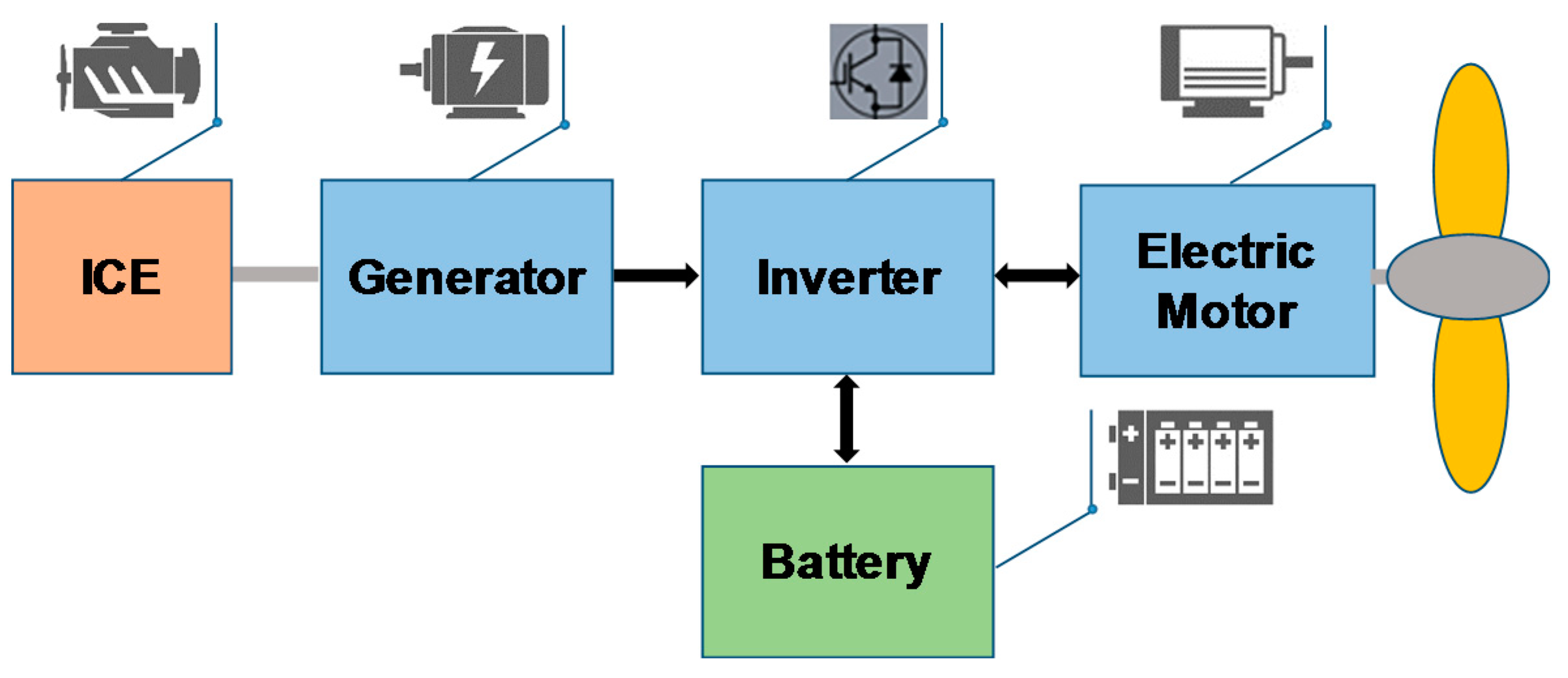
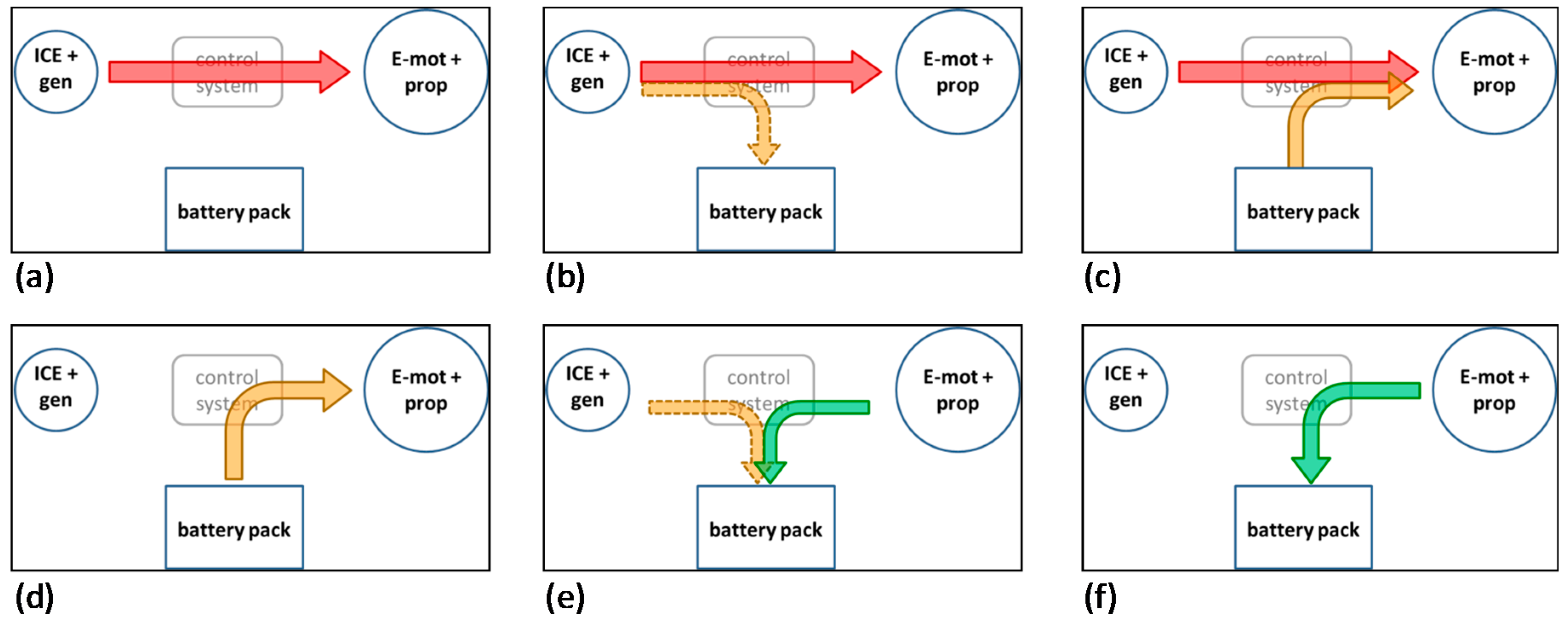
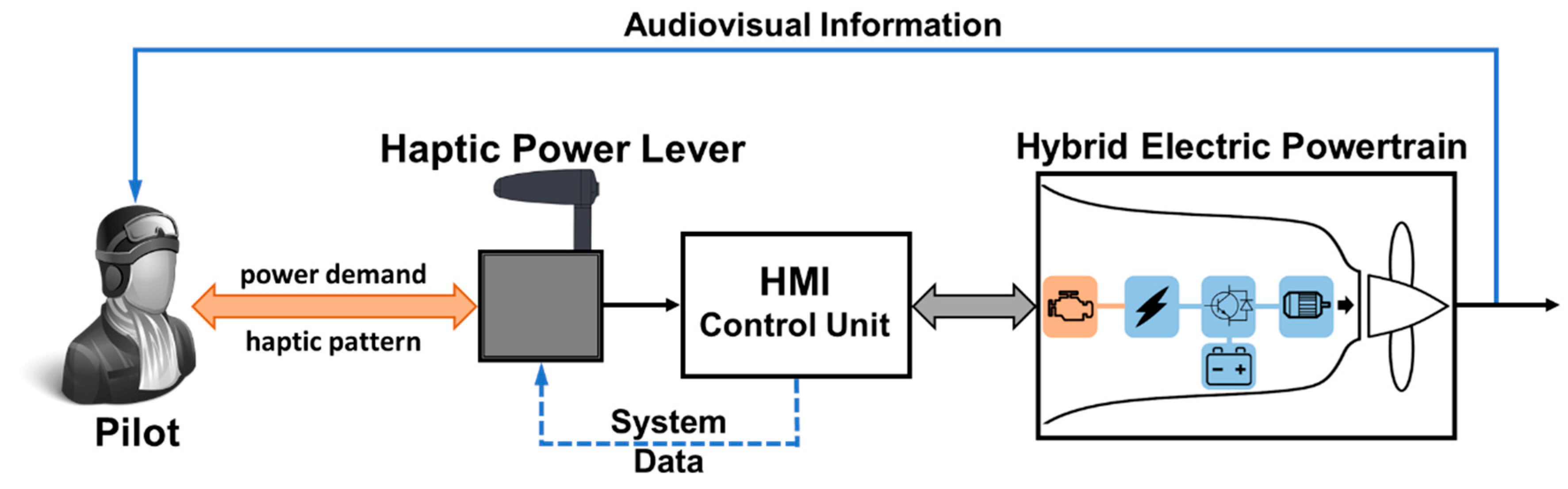
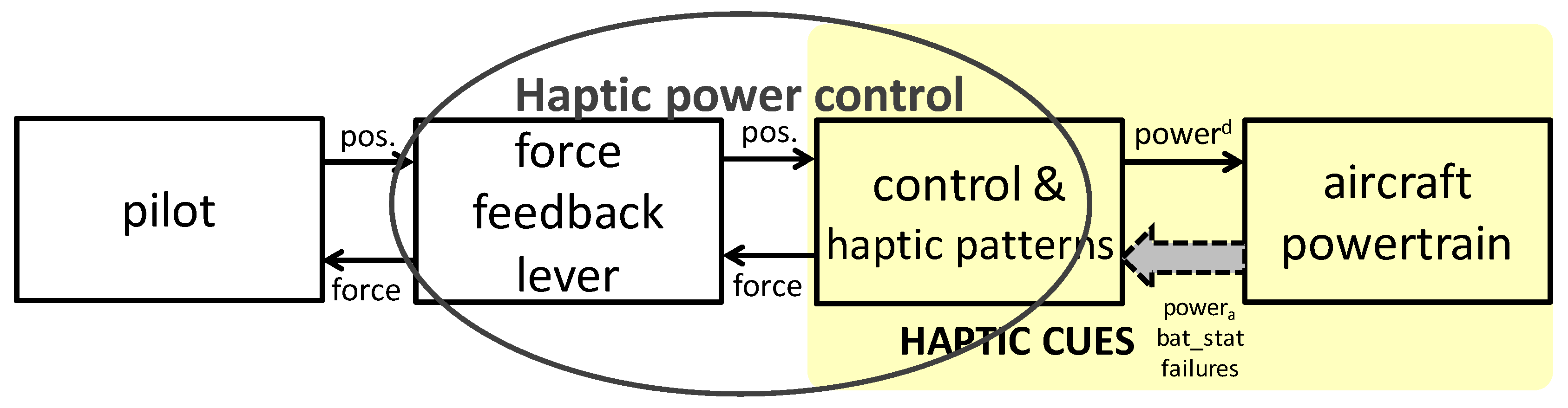
2.1. The Main Concept of the Powertrain System Haptic Control
2.2. Human Haptics and the Biomechanical Model of a Human Arm
2.3. Haptic Patterns
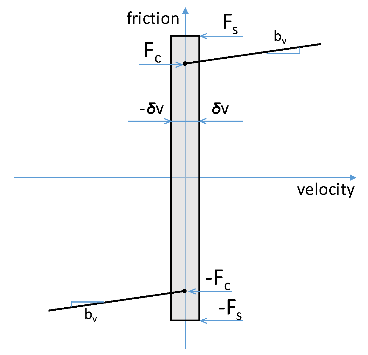
2.3.1. Friction
2.3.2. Bumps
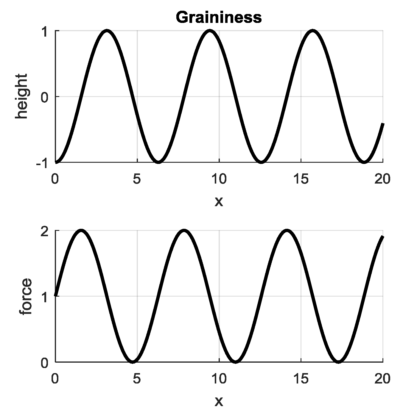
2.3.3. Graininess
2.3.4. Constant Return Force
2.4. The Control Algorithm for the Haptic Interface
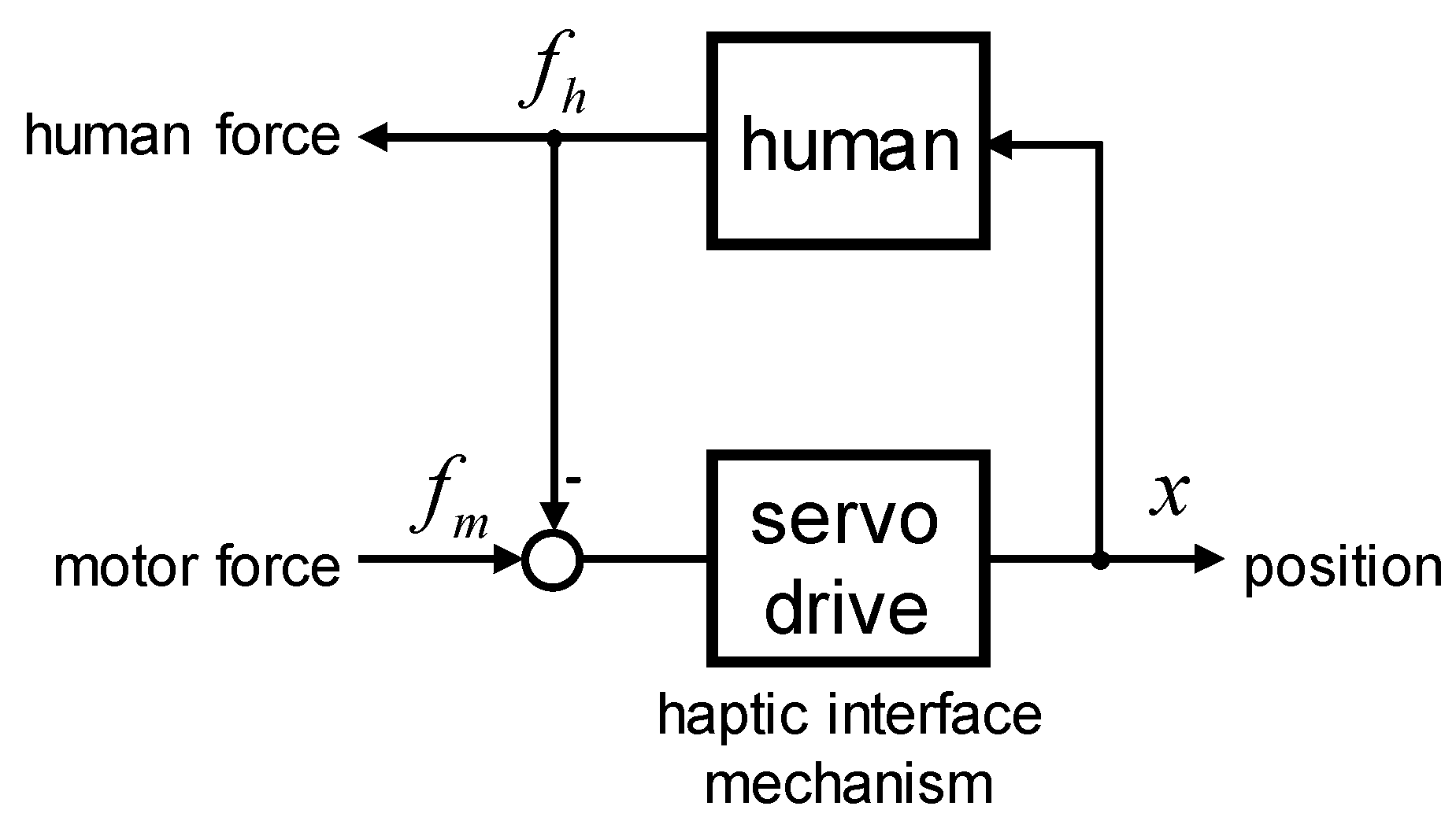
2.4.1. The Dynamic Model of the Haptic Interface
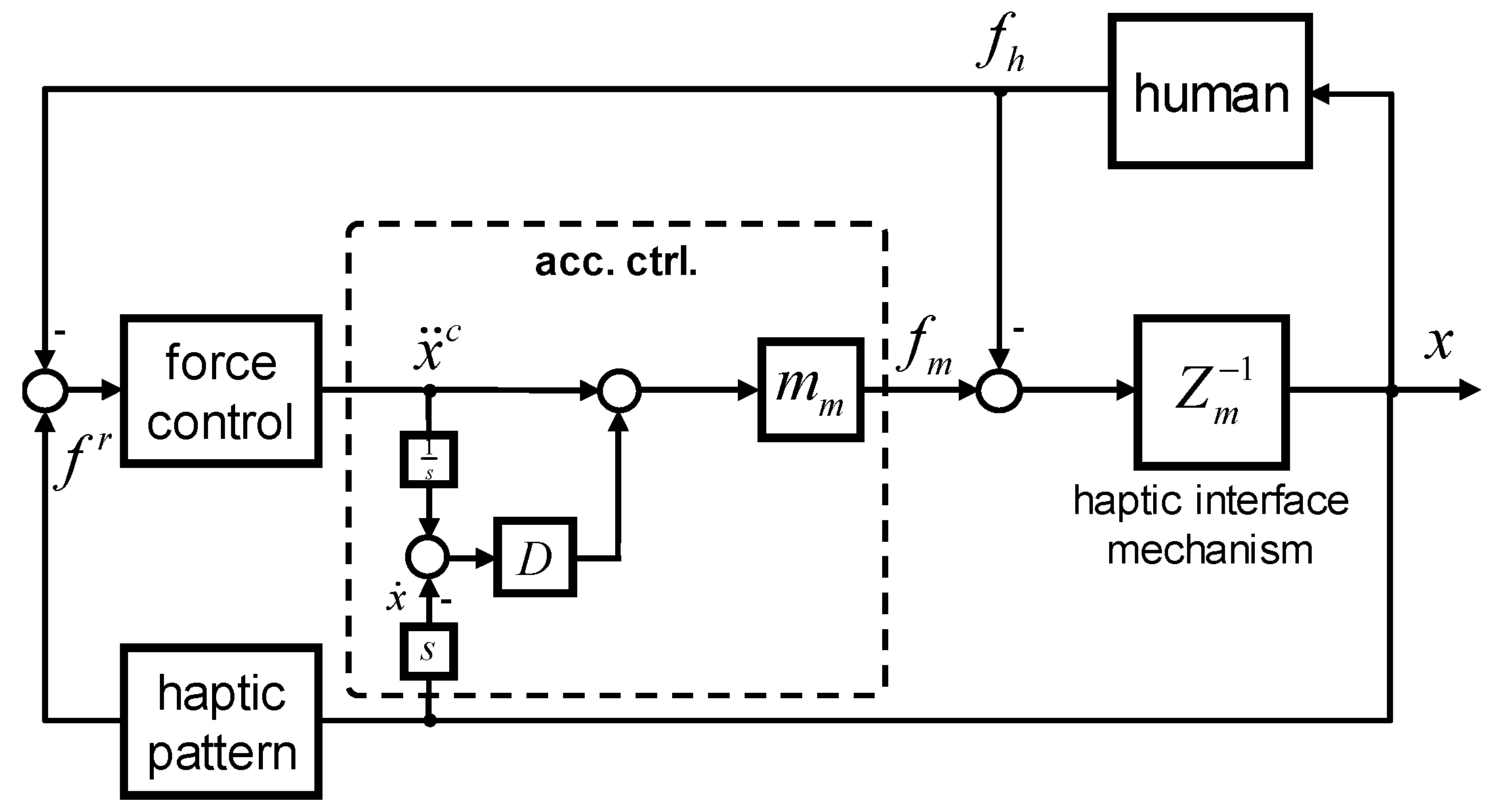
2.4.2. The Impedance Control
2.4.3. Derivation of the Control Algorithm
Chattering-Free SMC Design
Force Control
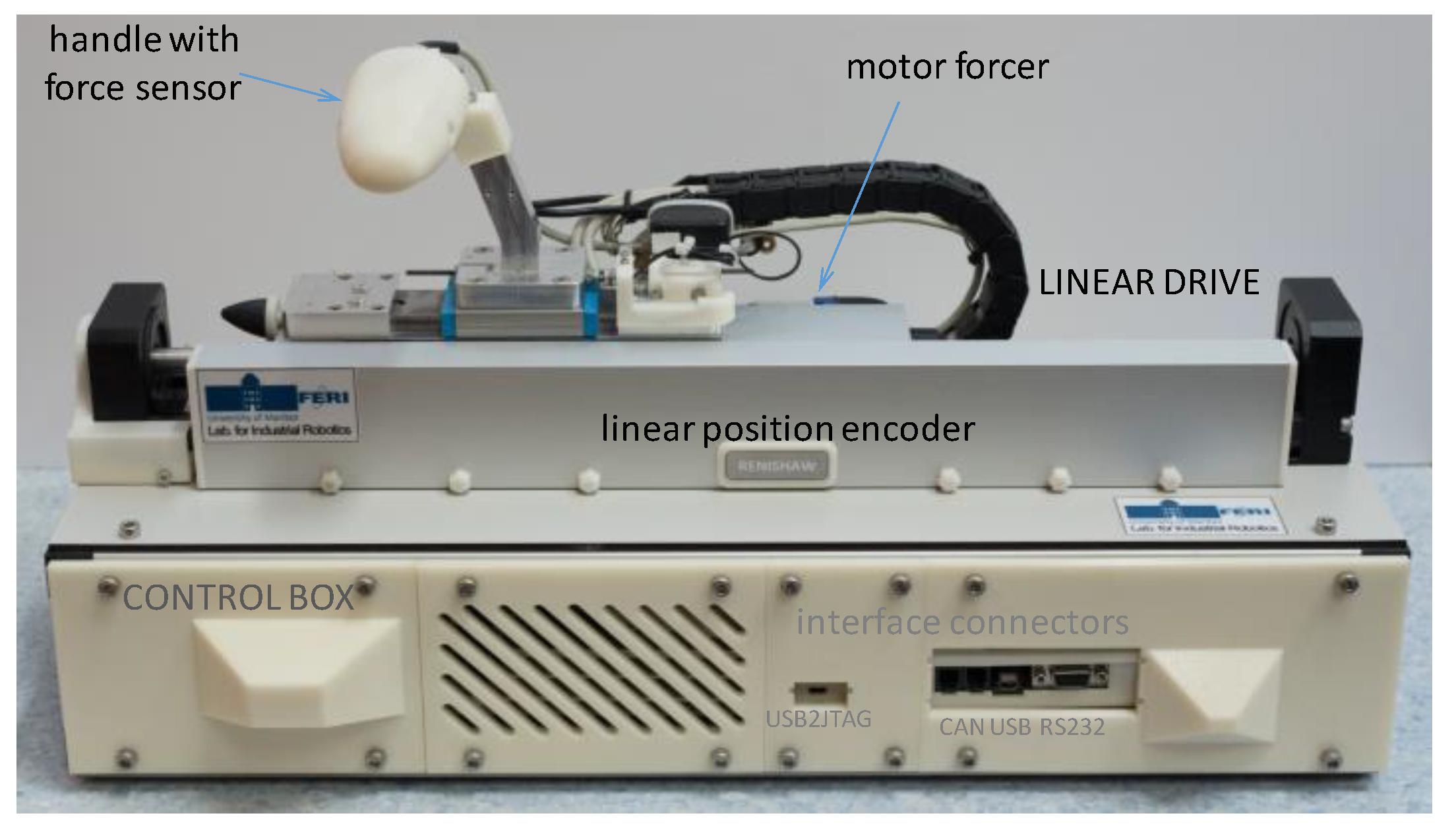
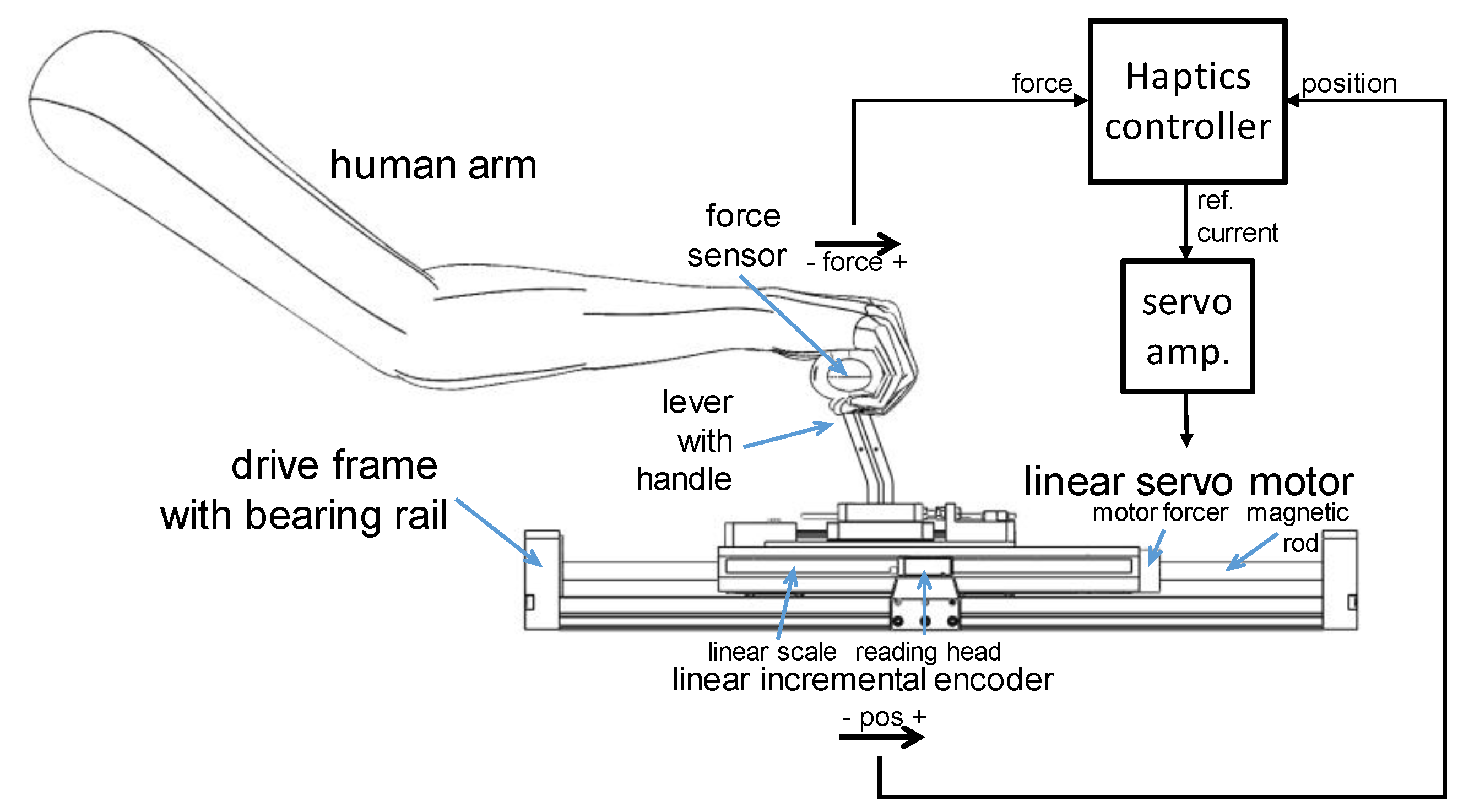
2.5. The Experimental System
3. Results
- Friction: , , , , and ;
- Bump: , , and ;
- Graininess: , and .
4. Discussion
5. Conclusions
Funding
Acknowledgments
Conflicts of Interest
References
- Varga, B.O.; Sagoian, A.; Mariasiu, F. Prediction of electric vehicle range: A comprehensive review of current issues and challenges. Energies 2019, 12, 946. [Google Scholar] [CrossRef]
- Berger, R. Aircraft electrical propulsion—The next chapter of aviation? Think:Act, 10 October 2017. [Google Scholar]
- Berger, R. Aircraft electrical propulsion—Onwards and upwards. Think:Act. July 2018. Available online: https://www.rolandberger.com/publications/publication_pdf/roland_berger_aircraft_electrical_propulsion_2.pdf (accessed on 1 August 2019).
- Bowman, C. Visions of the future: Hybrid electric aircraft propulsion. In AIAA Aircraft Electric/Hybrid-Electric Power & Propulsion Workshop; NASA: Salt Lake City, UT, USA, 2016. [Google Scholar]
- PIPISTREL. Electric Flight. Available online: https://www.pipistrel-aircraft.com/aircraft/electric-flight/ (accessed on 7 June 2019).
- Liu, X.; Qin, D.; Wang, S. Minimum energy management strategy of equivalent fuel consumption of hybrid electric vehicle based on improved global optimization equivalent factor. Energies 2019, 12, 2076. [Google Scholar] [CrossRef]
- Han, S.L.; Cui, S.M.; Song, L.W.; Chan, C.C. Electromagnetic analysis and design of switched reluctance double-rotor machine for hybrid electric vehicles. Energies 2014, 7, 6665–6688. [Google Scholar] [CrossRef]
- Lee, G.-S.; Kim, D.-H.; Han, J.-H.; Hwang, M.-H.; Cha, H.-R. Optimal operating point determination method design for range-extended electric vehicles based on real driving tests. Energies 2019, 12, 845. [Google Scholar] [CrossRef]
- Pan, C.; Liang, Y.; Chen, L.; Chen, L. Optimal control for hybrid energy storage electric vehicle to achieve energy saving using dynamic programming approach. Energies 2019, 12, 588. [Google Scholar] [CrossRef]
- Capata, R. Urban and extra-urban hybrid vehicles: A technological review. Energies 2018, 11, 2924. [Google Scholar] [CrossRef]
- Ullah, M.H.; Gunawan, T.S.; Sharif, M.R.; Muhida, R. Design of environmental friendly hybrid electric vehicle. In International Conference on Computer and Communication Engineering (ICCCE 2012); Springer: Kuala Lumpur, Malaysia, 2012; pp. 544–548. [Google Scholar]
- Friedrich, C.; Robertson, P. Hybrid-electric propulsion for aircraft. J. Aircr. 2015, 52, 176–189. [Google Scholar] [CrossRef]
- Friedrich, C.; Robertson, P.A. Hybrid-electric propulsion for automotive and aviation applications. CEAS Aeronaut. J. 2015, 6, 279–290. [Google Scholar] [CrossRef]
- Glassock, R.; Galea, M.; Williams, W.; Glesk, T. Hybrid electric aircraft propulsion case study for skydiving mission. Aerospace 2017, 4, 45. [Google Scholar] [CrossRef]
- Bergqvist, P. Hybrid electric aircraft motor powers up. Flying Magazine, 19 February 2016. [Google Scholar]
- Cipolla, V.; Oliviero, F. Hypsim: A simulation tool for hybrid aircraft performance analysis. In Variational Analysis and Aerospace Engineering Workshop-Mathematical Challenges for the Aerospace of the Future; Frediani, A., Mohammadi, B., Pironneau, O., Cipolla, V., Eds.; Springer: Cham, Switzerland; Erice, Italy, 2016; Volume 116. [Google Scholar]
- Zhang, R.F.; Xia, B.Z.; Li, B.H.; Cao, L.B.; Lai, Y.Z.; Zheng, W.W.; Wang, H.W.; Wang, W. State of the art of lithium-ion battery soc estimation for electrical vehicles. Energies 2018, 11, 1820. [Google Scholar] [CrossRef]
- Hypstair (EU fp7 Project). Available online: www.hypstair.eu (accessed on 11 June 2019).
- Gauci, J.; Cauchi, N.; Theuma, K.; Zammit-Mangion, D. Design and evaluation of a touch screen concept for pilot interaction with avionic systems. In Proceedings of the 2015 IEEE/AIAA 34th Digital Avionics Systems Conference (DASC), Prague, Czech Republic, 13–18 September 2015; pp. 1–32. [Google Scholar]
- Wang, L.; Wang, Y.; Chen, Y. Survey on introducing touch-screen into civil aircraft cockpit: Opinions of aircraft designers and pilots. In IET Conference Proceedings; Institution of Engineering and Technology: London, UK, 2018; pp. 1260–1265. [Google Scholar]
- Grunwald, M. Human Haptic Perception Basics and Applications; Birkhäuser: Basel, Switzerland; Boston, MA, USA, 2008; p. ix. 676p. [Google Scholar]
- Hatzfeld, C.; Kern, T.A. Engineering haptic devices: A beginner’s guide. In Springer Series on Touch and Haptic Systems, 2nd ed.; Springer: London, UK, 2014; p. 573. [Google Scholar]
- Ganesh, G.; Osu, R.; Naito, E. Feeling the force: Returning haptic signals influence effort inference during motor coordination. Sci. Rep. 2013, 3, 2648. [Google Scholar] [CrossRef] [PubMed] [Green Version]
- Hesse, P.; Nielsen, G. Haptic Signals—139 New and Known Signals; Danish DeafBlind Association: Aalborg, Denmark, 2018. [Google Scholar]
- Moussette, C. Simple Haptics—Sketching Perspectives for the Design of Haptic Interactions; Umeå University: Umeå, Sweden, 2012. [Google Scholar]
- El Saddik, A.; Orozco, M.; Eid, M.; Cha, J. Haptics Technologies–Bringing Touch to Multimedia; Springer: Berlin, Germany; New York, NY, USA, 2011; p. xv. 218p. [Google Scholar]
- Jones, L.A. Haptics; The MIT Press: Cambridge, MA, USA, 2018. [Google Scholar]
- Culbertson, H.; Schorr, S.B.; Okamura, A.M. Haptics: The present and future of artificial touch sensation. Ann. Rev. Control Robot. Auton. Syst. 2018, 1, 385–409. [Google Scholar] [CrossRef]
- Pedemonte, N.; Laliberté, T.; Gosselin, C. Bidirectional haptic communication: Application to the teaching and improvement of handwriting capabilities. Machines 2016, 4, 6. [Google Scholar] [CrossRef]
- Qin, H.; Song, A.; Liu, Y.; Jiang, G.; Zhou, B. Design and calibration of a new 6 DOF haptic device. Sensors 2015, 15, 31293–31313. [Google Scholar] [CrossRef] [PubMed]
- Barrow, A.; Harwin, W. Design and analysis of a haptic device design for large and fast movements. Machines 2016, 4, 8. [Google Scholar] [CrossRef]
- Franco, W.; Maffiodo, D.; De Benedictis, C.; Ferraresi, C. Use of mckibben muscle in a haptic interface. Robotics 2019, 8, 13. [Google Scholar] [CrossRef]
- Gosselin, F.; Ferlay, F.; Janot, A. Development of a new backdrivable actuator for haptic interfaces and collaborative robots. Actuators 2016, 5, 17. [Google Scholar] [CrossRef]
- Mihelj, M.; Podobnik, J. Haptics for Virtual Reality and Teleoperation; Springer: Dordrecht, The Netherlands; New York, NY, USA, 2012; Volume 64. [Google Scholar]
- Tavakoli, M.; Patel, R.V.; Moallem, M.; Aziminejad, A. Haptics for Teleoperated Surgical Robotic Systems; World Scientific Publishing Co. Pte. Ltd.: Singapore, 2008; Volume 1. [Google Scholar]
- Kawasaki, H. Robot Hands and Multi-Fingered Haptic Interfaces—Fundamentals and Applications; World Scientific Publishing Co. Pte. Ltd.: Singapore, 2015. [Google Scholar]
- Pacchierotti, C. Cutaneous Haptic Feedback in Robotic Teleoperation; Springer International Publishing: Cham, Switzerland, 2016. [Google Scholar]
- van Der Linde, R.Q.; Lammertse, P.; Frederiksen, E.; Ruiter, B. The hapticmaster, a new high-performance haptic interface. In Proceedings of the Eurohaptics Conference, Edinburgh, UK, 8–10 July 2002. [Google Scholar]
- Zhang, S.; Fu, Q.; Guo, S.; Fu, Y. A telepresence system for therapist-in-the-loop training for elbow joint rehabilitation. Appl. Sci. 2019, 9, 1710. [Google Scholar] [CrossRef]
- Ohnishi, K.; Mizoguchi, T. Real haptics and its applications. IEEJ Trans. Electr. Electron. Eng. 2017, 12, 803–808. [Google Scholar] [CrossRef] [Green Version]
- Kang Xiang, K.; Chin, P.J.H.; Rahman, H.A.; Yeong, C.F.; Su, E.L.M.; Narayanan, A.L.T. A novel haptic interface and control algorithm for robotic rehabilitation of stoke patients. In Proceedings of the 2014 IEEE Haptics Symposium (HAPTICS), Houston, TX, USA, 24–27 February 2014; pp. 421–426. [Google Scholar]
- Yang, C.; Xie, Y.; Liu, S.; Sun, D. Force modeling, identification, and feedback control of robot-assisted needle insertion: A survey of the literature. Sensors 2018, 18, 561. [Google Scholar] [CrossRef]
- Rodríguez, J.-L.; Velázquez, R.; Del-Valle-Soto, C.; Gutiérrez, S.; Varona, J.; Enríquez-Zarate, J. Active and passive haptic perception of shape: Passive haptics can support navigation. Electronics 2019, 8, 355. [Google Scholar] [CrossRef]
- Abbink, D.A.; Boer, E.R.; Mulder, M. Motivation for continuous haptic gas pedal feedback to support car following. In Proceedings of the 2008 IEEE Intelligent Vehicles Symposium, Eindhoven, The Netherlands, 4–6 June 2008; pp. 283–290. [Google Scholar]
- Mulder, M.; Mulder, M.; van Paassen, M.M.; Abbink, D.A. Haptic gas pedal feedback. Ergonomics 2008, 51, 1710–1720. [Google Scholar] [CrossRef]
- Bajcinca, N.; Cortesao, R.; Hauschild, M.; Bals, J.; Hirzinger, G. Haptic control for steer-by-wire systems. In Proceedings of the 2003 IEEE/RSJ International Conference on Intelligent Robots and Systems (IROS 2003), Las Vegas, NV, USA, 27–31 October 2003; Volume 2, pp. 2004–2009. [Google Scholar]
- Iqbal, J.; Zuhaib, K.; Han, C.; Khan, A.; Ali, M.A. Adaptive global fast sliding mode control for steer-by-wire system road vehicles. Appl. Sci. 2017, 7, 738. [Google Scholar] [CrossRef]
- Kurihara, Y.; Hachisu, T.; Sato, M.; Fukushima, S.; Kajimoto, H. Periodic tactile feedback for accelerator pedal control. In Proceedings of the 2013 World Haptics Conference (WHC), Daejeon, Korea, 14–17 April 2013; pp. 187–192. [Google Scholar]
- Bifulco, G.N.; Galante, F.; Pariota, L.; Spena, M.R. A linear model for the estimation of fuel consumption and the impact evaluation of advanced driving assistance systems. Sustainability 2015, 7, 14326–14343. [Google Scholar] [CrossRef]
- García-Canseco, E.; Ayemlong-Fokem, A.; Serrarens, A.; Steinbuch, M. A haptic gearshift interface for cars. In Proceedings of the International Conference EuroHaptics 2010, Amsterdam, The Netherlands, 8–10 July 2010; pp. 315–320. [Google Scholar]
- Gaffary, Y.; Lécuyer, A. The use of haptic and tactile information in the car to improve driving safety: A review of current technologies. Front. ICT 2018, 5. [Google Scholar] [CrossRef]
- Morales, J.; Mandow, A.; Martínez, J.L.; Reina, A.J.; García-Cerezo, A. Driver assistance system for passive multi-trailer vehicles with haptic steering limitations on the leading unit. Sensors 2013, 13, 4485–4498. [Google Scholar] [CrossRef]
- Judalet, V.; Glaser, S.; Gruyer, D.; Mammar, S. Fault detection and isolation via the interacting multiple model approach applied to drive-by-wire vehicles. Sensors 2018, 18, 2332. [Google Scholar] [CrossRef]
- Petermeijer, S.M.; Abbink, D.A.; Mulder, M.; de Winter, J.C.F. The effect of haptic support systems on driver performance: A literature survey. IEEE Trans. Haptics 2015, 8, 467–479. [Google Scholar] [CrossRef]
- Girbés, V.; Armesto, L.; Dols, J.; Tornero, J. Haptic feedback to assist bus drivers for pedestrian safety at low speed. IEEE Trans. Haptics 2016, 9, 345–357. [Google Scholar] [CrossRef]
- Jensen, M.J.; Tolbert, A.M.; Wagner, J.R.; Switzer, F.S.; Finn, J.W. A customizable automotive steering system with a haptic feedback control strategy for obstacle avoidance notification. IEEE Trans. Veh. Technol. 2011, 60, 4208–4216. [Google Scholar] [CrossRef]
- Condomines, J.P.; Defay, F.; Alazard, D. Robust impedance active control of flight control devices. IFAC Proc. Vol. 2014, 47, 8365–8371. [Google Scholar] [CrossRef] [Green Version]
- Goodrich, K.; Schutte, P.; Williams, R. Haptic-multimodal flight control system update. In Proceedings of the 11th AIAA Aviation Technology, Integration, and Operations (ATIO) Conference, Virginia Beach, VA, USA, 20–22 September 2011. [Google Scholar]
- Perez-Pinal, F.J.; Cervantes, I.; Diaz-Allen, I.; Maldonado, V. Design of a fly by wire technology system for an experimental more electric ultra-light aircraft. In Proceedings of the 2011 IEEE Vehicle Power and Propulsion Conference, Chicago, IL, USA, 6–9 September 2011; pp. 1–5. [Google Scholar]
- Schutte, P.C.; Goodrich, K.H.; Williams, R.A.D. Towards an Improved Pilot-Vehicle Interface for Highly Automated Aircraft: Evaluation of the Haptic Flight Control System. In Proceedings of the 4th AHFE International Conference on Applied Human Factors and Ergonomics, San Francisco, CA, USA, 21–25 July 2012. [Google Scholar]
- Grünhagen, W.; Müllhäuser, M.; Abildgaard, M.; Lantzsch, R. Active inceptors in FHS for pilot assistance systems. In Proceedings of the 36th European Rotorcraft Forum, Paris, France, 7–9 September 2010. [Google Scholar]
- P.E. Pilots will receive haptic feedback. Professional Engineering Magazine, 6 August 2014. [Google Scholar]
- Roberts, P. A World First: Civil Certification of BAE Systems’ Active Stick Technology; BAE Sytems: Farnborough, UK, 2018. [Google Scholar]
- Ziat, M.; Wagner, S.; Frissen, I. Haptic feedback to compensate for the absence of horizon cues during landing. In EuroHaptics 2016; Springer: London, UK, 2016. [Google Scholar]
- McGrath, B.; Cox, J.; McKay, J.; Rupert, A. Mission utility of a tactile display in rotary wing operations. In AHS 71th International Annual Forum; American Helicopter Society International, Inc.: Virginia Beach, VA, USA, 2015; Volume 2, pp. 1095–1104. [Google Scholar]
- D’Intino, G.; Olivari, M.; Geluardi, S.; Fabbroni, D.; Bülthoff, H.; Pollini, L. A pilot intent estimator for haptic support systems in helicopter maneuvering tasks. In Proceedings of the 2018 AIAA Modeling and Simulation Technologies Conference, Kissimmee, FL, USA, 8–12 January 2018. [Google Scholar]
- Olivari, M.; Nieuwenhuizen, F.M.; Bülthoff, H.; Pollini, L. An experimental comparison of haptic and automated pilot support systems. In Proceedings of the AIAA Modeling and Simulation Technologies Conference 2014, Atlanta, GA, USA, 16–20 June 2014. [Google Scholar]
- Klyde, D.; Ying-Liang, C.; Richards, N.; Cogan, B. Use of active inceptor cueing to mitigate pilot-vehicle system loss of control. In Proceedings of the AIAA Guidance, Navigation, and Control Conference, Minneapolis, MN, USA, 13–16 August 2012. [Google Scholar]
- Colonnese, N.; Sketch, S.M.; Okamura, A.M. Closed-loop stiffness and damping accuracy of impedance-type haptic displays. In Proceedings of the 2014 IEEE Haptics Symposium (HAPTICS), Houston, TX, USA, 24–27 February 2014; pp. 97–102. [Google Scholar]
- Parthiban, C.; Zinn, M. Performance and stability limitations of admittance-based haptic interfaces. In Proceedings of the 2018 IEEE Haptics Symposium (HAPTICS), San Francisco, CA, USA, 25–28 March 2018; pp. 58–65. [Google Scholar]
- Kazerooni, H.; Ming-Guo, H. The dynamics and control of a haptic interface device. IEEE Trans. Robot. Autom. 1994, 10, 453–464. [Google Scholar] [CrossRef]
- Carignan, C.; Cleary, K. Closed-loop force control for haptic simulation of virtual environments. Haptics-e Electron. J. Haptics Res. 2000, 1. [Google Scholar]
- Abdossalami, A.; Sirouspour, S. Adaptive control of haptic interaction with impedance and admittance type virtual environments. In Proceedings of the 2008 Symposium on Haptic Interfaces for Virtual Environment and Teleoperator Systems, Reno, NV, USA, 13–14 March 2008; pp. 145–152. [Google Scholar]
- Šabanović, A.; Ohnishi, K. Motion Control Systems; John Wiley & Sons (Asia) Pte Ltd.: South Tower, Singapore, 2011. [Google Scholar]
- Suzuki, S.; Furuta, K. Adaptive impedance control to enhance human skill on a haptic interface system. J. Control Sci. Eng. 2012, 2012, 365067. [Google Scholar] [CrossRef]
- Wu, Q.; Wu, H. Development, dynamic modeling, and multi-modal control of a therapeutic exoskeleton for upper limb rehabilitation training. Sensors 2018, 18, 3611. [Google Scholar] [CrossRef]
- Karnopp, D. Computer simulation of stick-slip friction in mechanical dynamic systems. J. Dyn. Syst. Meas. Control 1985, 107, 100–103. [Google Scholar] [CrossRef]
- Armstrong-Hélouvry, B.; Dupont, P.; Wit, C.C.D. A survey of models analysis tools and compensation methods for the control of machines with friction. Automatica 1994, 30, 1083–1138. [Google Scholar] [CrossRef]
- deWit, C.C.; Olsson, H.; Astrom, K.J.; Lischinsky, P. A new model for control of systems with friction. IEEE Trans. Autom. Control 1995, 40, 419–425. [Google Scholar]
- Olsson, H.; Åström, K.J.; deWit, C.C.; Gäfvert, M.; Lischinsky, P. Friction models and friction compensation. Eur. J. Control 1998, 4, 176–195. [Google Scholar] [CrossRef]
- Åström, K.J. Control of systems with friction. In Proceedings of the Fourth International Conference on Motion and Vibration Control, Zurich, Switzerland, 25–28 August 1998; pp. 25–32. [Google Scholar]
- Hensen, R.H.A.; van de Molengraft, M.J.G.; Steinbuch, M. Frequency domain identification of dynamic friction model parameters. IEEE Trans. Control Syst. Technol. 2002, 10, 191–196. [Google Scholar] [CrossRef]
- Wilhelm, F.; Tamura, T.; Fuchs, R.; Müllhaupt, P. Friction compensation control for power steering. IEEE Trans. Control Syst. Technol. 2016, 24, 1354–1367. [Google Scholar] [CrossRef]
- Bernstein, N.L.; Lawrence, D.A.; Pao, L.Y. Friction modeling and compensation for haptic interfaces. In Proceedings of the First Joint Eurohaptics Conference and Symposium on Haptic Interfaces for Virtual Environment and Teleoperator Systems, Pisa, Italy, 18–20 March 2005; pp. 290–295. [Google Scholar]
- Kikuuwe, R.; Takesue, N.; Sano, A.; Mochiyama, H.; Fujimoto, H. Admittance and impedance representations of friction based on implicit euler integration. IEEE Trans. Robot. 2006, 22, 1176–1188. [Google Scholar] [CrossRef]
- Ueberle, M.-W. Design, Control and Evaluation of a Family of Kinesthetic Haptic Interfaces; Technischen Universität München: Munich, Germany, 2006. [Google Scholar]
- Hogan, N. Controlling impedance at the man/machine interface. In Proceedings of the 1989 International Conference on Robotics and Automation, Scottsdale, AZ, USA, 14–19 May1989; Volume 3, pp. 1626–1631. [Google Scholar]
- Hill, M.D.; Niemeyer, G. Real-time estimation of human impedance for haptic interfaces. In Proceedings of the World Haptics 2009—Third Joint EuroHaptics conference and Symposium on Haptic Interfaces for Virtual Environment and Teleoperator Systems, Salt Lake City, UT, USA, 18–20 March 2009; pp. 440–445. [Google Scholar]
- Utkin, V.I. Sliding Modes in Control and Optimization; Springer: Berlin/Heidelberg, Germany; New York, NY, USA, 1992. [Google Scholar]
- Doan, Q.V.; Le, T.D.; Vo, A.T. Synchronization full-order terminal sliding mode control for an uncertain 3-DOF planar parallel robotic manipulator. Appl. Sci. 2019, 9, 1756. [Google Scholar] [CrossRef]
- Kallu, K.D.; Abbasi, S.J.; Khan, H.; Wang, J.; Lee, M.C. Tele-operated bilateral control of hydraulic manipulator using a robust controller based on the sensorless estimated reaction force. Appl. Sci. 2019, 9, 1995. [Google Scholar] [CrossRef]
- Geng, G.; Shen, Q.; Jiang, H. ANFTS mode control for an electronically controlled hydraulic power steering system on a permanent magnet slip clutch. Energies 2019, 12, 1739. [Google Scholar] [CrossRef]
- Bai, R. Adaptive sliding-mode control of automotive electronic throttle in the presence of input saturation constraint. IEEE/CAA J. Autom. Sin. 2018, 5, 878–884. [Google Scholar] [CrossRef]
- Mohd Zaihidee, F.; Mekhilef, S.; Mubin, M. Robust speed control of PMSM using sliding mode control (SMC)—A review. Energies 2019, 12, 1669. [Google Scholar] [CrossRef]
- Svečko, R.; Gleich, D.; Chowdhury, A.; Sarjaš, A. Sub-optimal second-order sliding mode controller parameters’ selection for a positioning system with a synchronous reluctance motor. Energies 2019, 12, 1855. [Google Scholar] [CrossRef]
- Derbeli, M.; Barambones, O.; Ramos-Hernanz, J.A.; Sbita, L. Real-time implementation of a super twisting algorithm for PEM fuel cell power system. Energies 2019, 12, 1594. [Google Scholar] [CrossRef]
- Sabanovic, A.; Fridman, L.M.; Spurgeon, S. Variable Structure Systems: From Principles to Implementation; The Institution of Electrical Engineers: London, UK, 2004. [Google Scholar]
- Young, K.D.; Utkin, V.I.; Ozguner, U. A control engineer’s guide to sliding mode control. IEEE Trans. Control Syst. Technol. 1999, 7, 328–342. [Google Scholar] [CrossRef]
- Fridman, L.; Levant, A. Higher order sliding modes as a natural phenomenon in control theory. In Robust Control via Variable Structure and Lyapunov Techniques; Garofalo, F., Glielmo, L., Eds.; Springer: Berlin/Heidelberg, Germany, 1996; pp. 107–133. [Google Scholar]
- Bartolini, G.; Ferrara, A.; Usai, E. Chattering avoidance by second-order sliding mode control. IEEE Trans. Autom. Control 1998, 43, 241–246. [Google Scholar] [CrossRef]
- Shtessel, Y.; Edwards, C.; Fridman, L.; Levant, A. Sliding Mode Control and Observation; Springer Science+Business Media (Birkhauser): New York, NY, USA, 2014. [Google Scholar]
- Utkin, V. Discussion aspects of high-order sliding mode control. IEEE Trans. Autom. Control 2016, 61, 829–833. [Google Scholar] [CrossRef]
- Hace, A.; Jezernik, K.; Uran, S. Robust impedance control. In The 1998 IEEE International Conference on Control Applications; IEEE: Trieste, Italy, 1998; Volume 1, pp. 583–587. [Google Scholar]
- Hace, A.; Jezernik, K.; Sabanovic, A. Improved design of VSS controller for a linear belt-driven servomechanism. IEEE/ASME Trans. Mechatron. 2005, 10, 385–390. [Google Scholar] [CrossRef]
- Hace, A.; Jezernik, K.; Sabanovic, A. SMC with disturbance observer for a linear belt drive. IEEE Trans. Ind. Electron. 2007, 54, 3402–3412. [Google Scholar] [CrossRef]
- Hace, A.; Franc, M. FPGA implementation of sliding-mode-control algorithm for scaled bilateral teleoperation. IEEE Trans. Ind. Inform. 2013, 9, 1291–1300. [Google Scholar] [CrossRef]
- Hace, A.; Franc, M. Pseudo-sensorless high-performance bilateral teleoperation by sliding-mode control and FPGA. IEEE/ASME Trans. Mechatron. 2014, 19, 384–393. [Google Scholar] [CrossRef]
- Hace, A.; Golob, M. Chattering-free sliding mode control algorithm for a haptic throttle lever. In Proceedings of the IECON 2016-42nd Annual Conference of the IEEE Industrial Electronics Society, Florence, Italy, 24–27 October 2016; pp. 6385–6390. [Google Scholar]
- Ghaffari, T.K.; Kövecses, J. A high-performance velocity estimator for haptic applications. In Proceedings of the 2013 World Haptics Conference (WHC), Daejeon, Korea, 14–17 April 2013; pp. 127–132. [Google Scholar]
- Chawda, V.; Celik, O.; O’Malley, M.K. Evaluation of velocity estimation methods based on their effect on haptic device performance. IEEE/ASME Trans. Mechatron. 2018, 23, 604–613. [Google Scholar] [CrossRef]
- MacLean, K.E. Haptic interaction design for everyday interfaces. Rev. Hum. Factors Ergon. 2008, 4, 149–194. [Google Scholar] [CrossRef]
- Kosuge, K.; Fujisawa, Y.; Fukuda, T. Control of mechanical system with man-machine interaction. In Proceedings of the IEEE/RSJ International Conference on Intelligent Robots and Systems, Raleigh, NC, USA, 7–10 July 1992. [Google Scholar]
- Lawrence, D.A. Stability and transparency in bilateral teleoperation. IEEE Trans. Robot. Autom. 1993, 9, 624–637. [Google Scholar] [CrossRef]
- Tsuji, T.; Goto, K.; Moritani, M.; Kaneko, M.; Morasso, P. Spatial characteristics of human hand impedance in multi-joint arm movements. In Proceedings of the IEEE/RSJ International Conference on Intelligent Robots and Systems (IROS’94), Munich, Germany, 12–16 September 1994; Volume 1, pp. 423–430. [Google Scholar]
- Speich, J.E.; Shao, L.; Goldfarb, M. Modeling the human hand as it interacts with a telemanipulation system. Mechatronics 2005, 15, 1127–1142. [Google Scholar] [CrossRef]
- Fu, M.J.; Cavusoglu, M.C. Three-dimensional human arm and hand dynamics and variability model for a stylus-based haptic interface. In 2010 IEEE International Conference on Robotics and Automation; IEEE: Anchorage, AK, USA, 2010; pp. 1339–1346. [Google Scholar]
- Kovács, L.L.; Kövecses, J. Dynamics of coupled haptic systems. In 2015 IEEE World Haptics Conference (WHC); IEEE: Evanston, IL, USA, 2015; pp. 286–292. [Google Scholar]
- Berger, E.J. Friction modeling for dynamic system simulation. Appl. Mech. Rev. 2002, 55, 535–577. [Google Scholar] [CrossRef] [Green Version]
- Richard, C.; Cutkosky, M.R. Friction modeling and display in haptic applications involving user performance. In Proceedings of the 2002 IEEE International Conference on Robotics and Automation, Washington, DC, USA, 11–15 May 2002; Volume 1, pp. 605–611. [Google Scholar]
- Lin, M.C.; Otaduy, M.A. Haptic Rendering: Foundations, Algorithms, and Applications; A K Peters, Ltd.: Wellesley, MA, USA, 2008. [Google Scholar]
- Minsky, M.D.R. Computational Haptics: The Sandpaper System for Synthesizing Texture for a Force-Feedback Display; Massachusetts Institute of Technology, MIT: Cambridge, MA, USA, 1995. [Google Scholar]
- Robles-De-La-Torre, G.; Hayward, V. Virtual surfaces and haptic shape perception. In Proceedings of the Haptic Interfaces for Virtual Environment and Teleoperator Systems Symposium, ASME International Mechanical Engineering Congress & Exposition 2000, Orlando, FL, USA, 5–10 November 2000. [Google Scholar]
- Robles-De-La-Torre, G.; Hayward, V. Force can overcome object geometry in the perception of shape through active touch. Nature 2001, 412, 445–448. [Google Scholar] [CrossRef]
- Hogan, N. Impedance control: An approach to manipulation: Part i—Theory. J. Dyn. Syst. Meas. Control 1985, 107, 1–7. [Google Scholar] [CrossRef]
- Hogan, N. Impedance control: An approach to manipulation: Part ii—Implementation. J. Dyn. Syst. Meas. Control 1985, 107, 8–16. [Google Scholar] [CrossRef]
- Hogan, N. Impedance control: An approach to manipulation: Part iii—Applications. J. Dyn. Syst. Meas. Control 1985, 107, 17–24. [Google Scholar] [CrossRef]
- Yen, S.-H.; Tang, P.-C.; Lin, Y.-C.; Lin, C.-Y. Development of a virtual force sensor for a low-cost collaborative robot and applications to safety control. Sensors 2019, 19, 2603. [Google Scholar] [CrossRef]
- Han, J.-H.; Kim, D.-H.; Hwang, M.-H.; Lee, G.-S.; Cha, H.-R. Active virtual impedance control for sound-following robots to avoid obstacles. Electronics 2019, 8, 522. [Google Scholar] [CrossRef]
- Nadeau, N.A.; Bonev, I.A.; Joubair, A. Impedance control self-calibration of a collaborative robot using kinematic coupling. Robotics 2019, 8, 33. [Google Scholar] [CrossRef]
- Li, C.; Zhang, Z.; Xia, G.; Xie, X.; Zhu, Q. Efficient force control learning system for industrial robots based on variable impedance control. Sensors 2018, 18, 2539. [Google Scholar] [CrossRef]
- Ba, K.; Yu, B.; Gao, Z.; Li, W.; Ma, G.; Kong, X. Parameters sensitivity analysis of position-based impedance control for bionic legged robots’ hdu. Appl. Sci. 2017, 7, 1035. [Google Scholar] [CrossRef]
- Chen, C.; Nie, H.; Chen, J.; Wang, X. A velocity-based impedance control system for a low impact docking mechanism (lidm). Sensors 2014, 14, 22998–23016. [Google Scholar] [CrossRef]
- Zhang, T.; Xia, J. Interconnection and damping assignment passivity-based impedance control of a compliant assistive robot for physical human–robot interactions. IEEE Robot. Autom. Lett. 2019, 4, 538–545. [Google Scholar] [CrossRef]
- Ba, K.; Yu, B.; Ma, G.; Zhu, Q.; Gao, Z.; Kong, X. A novel position-based impedance control method for bionic legged robots’ hdu. IEEE Access 2018, 6, 55680–55692. [Google Scholar] [CrossRef]
- Jamwal, P.K.; Hussain, S.; Ghayesh, M.H.; Rogozina, S.V. Impedance control of an intrinsically compliant parallel ankle rehabilitation robot. IEEE Trans. Ind. Electron. 2016, 63, 3638–3647. [Google Scholar] [CrossRef]
- Li, Z.; Liu, J.; Huang, Z.; Peng, Y.; Pu, H.; Ding, L. Adaptive impedance control of human–robot cooperation using reinforcement learning. IEEE Trans. Ind. Electron. 2017, 64, 8013–8022. [Google Scholar] [CrossRef]
- Toedtheide, A.; Lilge, T.; Haddadin, S. Antagonistic impedance control for pneumatically actuated robot joints. IEEE Robot. Autom. Lett. 2016, 1, 161–168. [Google Scholar] [CrossRef]
- Pérez-Ibarra, J.C.; Siqueira, A.A.G.; Silva-Couto, M.A.; de Russo, T.L.; Krebs, H.I. Adaptive impedance control applied to robot-aided neuro-rehabilitation of the ankle. IEEE Robot. Autom. Lett. 2019, 4, 185–192. [Google Scholar] [CrossRef]
- Raiola, G.; Cardenas, C.A.; Tadele, T.S.; de Vries, T.; Stramigioli, S. Development of a safety- and energy-aware impedance controller for collaborative robots. IEEE Robot. Autom. Lett. 2018, 3, 1237–1244. [Google Scholar] [CrossRef]
- Devie, S.; Robet, P.; Aoustin, Y.; Gautier, M. Impedance control using a cascaded loop force control. IEEE Robot. Autom. Lett. 2018, 3, 1537–1543. [Google Scholar] [CrossRef]
- Lawrence, D.A. Impedance control stability properties in common implementations. In Proceedings of the 1988 IEEE International Conference on Robotics and Automation, Philadelphia, PA, USA, 24–29 April 1988; Volume 1182, pp. 1185–1190. [Google Scholar]
- Newman, W.S. Stability and performance limits of interaction controllers. J. Dyn. Syst. Meas. Control 1992, 114, 563–570. [Google Scholar] [CrossRef]
- Adams, R.J.; Hannaford, B. Stable haptic interaction with virtual environments. IEEE Trans. Robot. Autom. 1999, 15, 465–474. [Google Scholar] [CrossRef]
- Gil, J.J.; Avello, A.; Rubio, A.; Florez, J. Stability analysis of a 1 DOF haptic interface using the routh-hurwitz criterion. IEEE Trans. Control Syst. Technol. 2004, 12, 583–588. [Google Scholar] [CrossRef]
- Gupta, A.; Patoglu, V.; O’Malley, M. Disturbance observer based closed loop force control for haptic feedback. In Proceedings of the 2007 ASME International Mechanical Engineering Congress and Exposition, Seattle, WA, USA, 11–15 November 2007. [Google Scholar]
- Katsura, S.; Matsumoto, Y.; Ohnishi, K. Modeling of force sensing and validation of disturbance observer for force control. IEEE Trans. Ind. Electron. 2007, 54, 530–538. [Google Scholar] [CrossRef]
- Sariyildiz, E.; Ohnishi, K. An adaptive reaction force observer design. IEEE/ASME Trans. Mechatron. 2015, 20, 750–760. [Google Scholar] [CrossRef]
- Sariyildiz, E.; Oboe, R.; Ohnishi, K. Disturbance observer-based robust control and its applications: 35th anniversary overview. IEEE Trans. Ind. Electron. 2019. [Google Scholar] [CrossRef]
- Hsueh, P.; Chen, J.; Yao, W.; Tsai, M.; Syu, W. Luenberger observer-based impedance control of linear servo motor for a desired haptic system. In Proceedings of the 2013 CACS International Automatic Control Conference (CACS), Nantou, Taiwan, 2–4 December 2013; pp. 140–145. [Google Scholar]
- Yano, T.; Ohnishi, K. Force control for a haptic interface system. In Proceedings of the IEEE ICIT ’04 2004 IEEE International Conference on Industrial Technology, Hammamet, Tunisia, 8–10 December 2004; Volume 1, pp. 102–107. [Google Scholar]
- Liu, T.; Li, C.; Inoue, Y.; Shibata, K. Reaction force/torque sensing in a master-slave robot system without mechanical sensors. Sensors 2010, 10, 7134–7145. [Google Scholar] [CrossRef]
- Kallu, K.D.; Wang, J.; Abbasi, S.J.; Lee, M.C. Estimated reaction force-based bilateral control between 3dof master and hydraulic slave manipulators for dismantlement. Electronics 2018, 7, 256. [Google Scholar] [CrossRef]
- Čurkovič, M.; Pučko, R.; Golob, M.; Hace, A. Two-axis controller for rapid prototyping in robotic applications (in slovene). Ventil (Ljubljana) 2017, 23, 208–213. [Google Scholar]
- Hace, A. The improved division-less MT-type velocity estimation algorithm for low-cost fpgas. Electronics 2019, 8, 361. [Google Scholar] [CrossRef]
- Martínez-García, M.; Gordon, T.; Shu, L. Extended crossover model for human-control of fractional order plants. IEEE Access 2017, 5, 27622–27635. [Google Scholar] [CrossRef]
- Martinez-Garcia, M.; Gordon, T. A new model of human steering using far-point error perception and multiplicative control. In Proceedings of the 2018 IEEE International Conference on Systems, Man, and Cybernetics (SMC), Vienna, Austria, 2–5 July 2018; pp. 1245–1250. [Google Scholar]


| Parameter | Value | Unit |
|---|---|---|
| 1.8 | (kg) | |
| 100–1000 | (s−1) | |
| 1.8–0.5 | (kg) | |
| 0 | (Ns/m) |
© 2019 by the author. Licensee MDPI, Basel, Switzerland. This article is an open access article distributed under the terms and conditions of the Creative Commons Attribution (CC BY) license (http://creativecommons.org/licenses/by/4.0/).
Share and Cite
Hace, A. The Advanced Control Approach based on SMC Design for the High-Fidelity Haptic Power Lever of a Small Hybrid Electric Aircraft. Energies 2019, 12, 2974. https://doi.org/10.3390/en12152974
Hace A. The Advanced Control Approach based on SMC Design for the High-Fidelity Haptic Power Lever of a Small Hybrid Electric Aircraft. Energies. 2019; 12(15):2974. https://doi.org/10.3390/en12152974
Chicago/Turabian StyleHace, Aleš. 2019. "The Advanced Control Approach based on SMC Design for the High-Fidelity Haptic Power Lever of a Small Hybrid Electric Aircraft" Energies 12, no. 15: 2974. https://doi.org/10.3390/en12152974
APA StyleHace, A. (2019). The Advanced Control Approach based on SMC Design for the High-Fidelity Haptic Power Lever of a Small Hybrid Electric Aircraft. Energies, 12(15), 2974. https://doi.org/10.3390/en12152974