Article

Hierarchical Control with Fast Primary Control for Multiple Single-Phase Electric Springs

1
School of Electrical Engineering, Southeast University, Nanjing 210096, China
2
State Grid Huzhou Power Supply Company, Huzhou 313000, China
3
Department of Industrial Engineering, University of Padova, 35131 Padova, Italy
*
Author to whom correspondence should be addressed.
Energies 2019, 12(18), 3511; https://doi.org/10.3390/en12183511
Submission received: 22 July 2019 / Revised: 9 September 2019 / Accepted: 10 September 2019 / Published: 12 September 2019

Abstract

:
An electric spring (ES) is a new power compensation device which becomes useful for the large-scale integration of renewable energy sources into the grid. However, when the grid contains two or more ESs connected at different nodes, a voltage drop occurs between the nodes due to the line impedance. Therefore, the voltage of the ES-stabilized nodes cannot be set at the same reference (e.g., 220 V), otherwise one or more ESs break away because of the voltage windup. In this paper, a hierarchical control of multiple ESs tied to a microgrid is proposed to account for the line voltage drop. The primary control relies on the power decoupling control; it is designed for islanded operation of the microgrid, which improves the dynamics of both the voltage and frequency regulation. The secondary control relies on the droop control; it is introduced to coordinate the operation of the ESs by modifying the reference voltage of each ES dynamically. Advantages and disadvantages of the proposed hierarchical control are analyzed together with the explanations of the algorithms developed for its realization. At last, effectiveness of the arranged control system is validated by simulations on the MATLAB/Simulink platform.

Graphical Abstract

1. Introduction

Renewable energy sources (RESs) of solar and wind type are characterized by a non-predictable intermittency of power generation. When many RESs of these types contribute to the grid power, the uncertainty on their output power affects the power quality of the power system, with the occurrence of harmonics, voltage excursions, flickers, and even with the possible collapse of the power system [1,2]. An electric spring (ES) is a new power compensation device that provides a solution to the problem of grid power uncertainty. Indeed, it changes the traditional operation mode of the power system, whereby the load consumption determines the power generation, into a new one, whereby the automatic matching between power generation and load demand is implemented. Therefore, ES represents an effective solution to the large grid power fluctuations expected when RESs of solar/ wind type penetrate the grid on a large scale [3,4,5,6].
The keystone of the ES approach is to divide the loads of a user into two groups with different requirements: one is critical load (CL), and the other one is non-critical load (NCL). CL requires highly stabilized supply voltage and/or uninterrupted supply to work correctly, and it may operate in frequent situations at nearly the rated power; examples of CL are machine rooms and medical equipment. NCL allows its supply voltage -and, hence, its absorbed power- to vary within a larger range, and can even be cut off for a certain period of time when the total power supply is not enough to ensure the required voltage for the CL supply; examples of NCL are water heater and other heating equipment. Both CL and NCL are connected at the same grid node, called the point of common coupling (PCC), but in a different way: CL in a direct way while NCL through the interposition of ES.
An ES is made of a voltage direct current (DC) source, a voltage source inverter (VSI) and an alternating current (AC) output inductor-capacitor pair; the capacitor, placed between PCC and NCL, constitutes the ES output whilst the inductor plays the role of filtering the VSI output current. By suitably controlling the capacitor voltage, the NCL voltage is adjusted such that the grid-incoming power fluctuations are transferred to the NCL so that CL is supplied at the required voltage [3]. By this reason, the branch constituted by the capacitor and NCL is called the smart load (SL).
Two basic ES versions exist. One version utilizes a capacitor as voltage DC source, and the ES exchanges only reactive power with the SL branch to stabilize the CL voltage; this version is commonly referred to as ES-1. The other version utilizes a bidirectional DC source like a battery as voltage DC source, and the ES exchanges both active and reactive power with the SL branch to stabilize the CL voltage; this version is commonly referred to as ES-2. Besides stabilizing the CL voltage, ES-2s have the capabilities of executing other tasks such as the correction of the power factor (PF) of the user [7] or the suppression of the frequency [8] and voltage [9] excursions of the power system. Due to their capabilities, hereafter only the ES-2s are considered.
Various strategies have been developed for the ES control. The δ control, proposed in [10], instantaneously adjusts the phase angle δ between the PCC and line voltages to regulate the magnitude of the CL voltage and, at the same time, to keep the user PF compliant with the standards. The radial-chordal control strategy, proposed in [11], decomposes the ES output voltage into its chordal and radial components. Then it adjusts the chordal component to regulate the magnitude of the CL voltage ad the radial component to control the power angle of the SL. The active and reactive power control, proposed in [12], simplifies the ES control by using independent loops to adjust the CL voltage and the active power exchanged by the ES. Regarding the strategies for the control of multiple ESs, the droop control, presented in [13], manipulates the modulation index of the ES-embedded VSI to regulate the CL voltage at each node, which makes the solution appropriate for the ES-1 version. The consensus control, presented in [14,15], processes the voltage information coming from the adjacent ESs to calculate the reference voltage of the local ES; clearly, this control needs communication means to work.
There are other studies related to the control of multiple ESs. The simplified ES model established in [16] is intended to the simulation of a large-scale system endowed with the ESs. The modular dynamic model of the ES established in [17] is tailored for the integration of sophisticated control algorithms, reducing the order of the model by help of experimental measurements. In [18], the distributed voltage control attained with multiple ESs in a power system is compared to the single node voltage control done with the Static Synchronous Compensator (STATCOM); from the comparison executed under different voltage excursion situations, it emerges that the ESs provide a better voltage regulation than the STATCOM. The effect that the ES operation combined with an energy management strategy exerts on the suppression of the voltage and frequency excursions in microgrids is examined in [19]. In [20], hybrid ESs for grid-tied power control and storage reduction in AC microgrids is discussed. In [21], a method to stabilize a set of multiple ESs is presented, based on the small signal modeling of their behavior.
As a new paradigm of load demand management enabled by a power compensation device, the ES has outstanding advantages in adapting to the future distributed system when compared with the traditional centralized devices of reactive power compensation. However, the sizing power of a single ES is often limited. For the stabilization of the loads of a power system to take place, the joint effort of multiple ESs is requested, as exemplified in Figure 1. When multiple ESs are tied to different nodes of a power system, the node voltages are unable to reach the nominal value simultaneously (e.g., 220 V) due to the inherent voltage drop of the transmission line. Therefore, the adoption of an overall control strategy of the ESs becomes necessary to appropriately modify the local reference voltage of the ESs during the transients. The role of the strategy is to provide for a coordinate operation of the ESs while maintaining stabilized voltage across the associated CLs. Some papers have shown that the popular droop control is a useful tool on which to build up the strategy [22,23,24,25,26].
The existing popular hierarchical control is well illustrated in [25] which is derived from the international standard for the integration of enterprise and control systems (ISA-95) and electrical dispatching standards to endow smartness and flexibility to Microgrids (MGs). With such control, the MGs are able to work at both islanded or stiff-source-connected modes, as well as to achieve a seamless transfer from one mode to another. Besides, multiple MG clusters can be performed to constitute a smart grid. Moreover, the system becomes more flexible and expandable, and consequently, more and more MGs could be integrated without changing the local hierarchical control system associated to each MG. Compared to the hierarchical control in [25], traditional droop control has many disadvantages which need to be improved. For instance, it is not suitable when the paralleled system must share non-linear loads due to harmonic currents, frequency deviation, accuracy sharing between active and reactive power under islanded mode. The hierarchical control proposed in [25] consists of three levels: (1) the primary control is based on the droop control; (2) the secondary control allows the restoration of the deviations obtained by the primary control; and (3) the tertiary control manages the power flow between the MG and the external electrical distribution system. Although it has so many advantages, it is complicated and hard to build prototype in a laboratory with limited resources and space. Considering the simple structure of ES system, and in order to avoid the disadvantages of the traditional droop control and to take the advantage of the hierarchical control in [25], a simplified hierarchical control only containing the droop control and the inner control loops is adopted in this paper. Another contribution is that it is proposed that the power decoupling control with fast dynamic responses is adopted at the ES level. In details, the hierarchical control is structured into two levels: primary and secondary. Compared to the existing primary control solutions, a novel scheme is developed that enhances both the dynamics and the robustness of the ES operation. After discussing the inconveniences of multiple ESs working independently, their coordinate operation is accomplished by the secondary control; besides modifying the CL reference voltage at the different nodes by using droop characteristics, it is designed to cope with the frequency excursions that often arise in the islanded operation of a microgrid. Finally, the effectiveness of the novel ES control scheme as well as of the proposed hierarchical control is verified by simulation.
The organization of the paper is as follows. Section 2 shortly reviews topology and model of an ES-2. Section 3 illustrates the proposed coordinated control for multiple ESs tied to a microgrid and explains how the control steers the ESs. Section 4 presents and discusses the results of some significant simulations carried out on a set of three ESs governed with the proposed control. Finally, Section 5 concludes the paper.

2. Electric Spring (ES-2) Operating Principles
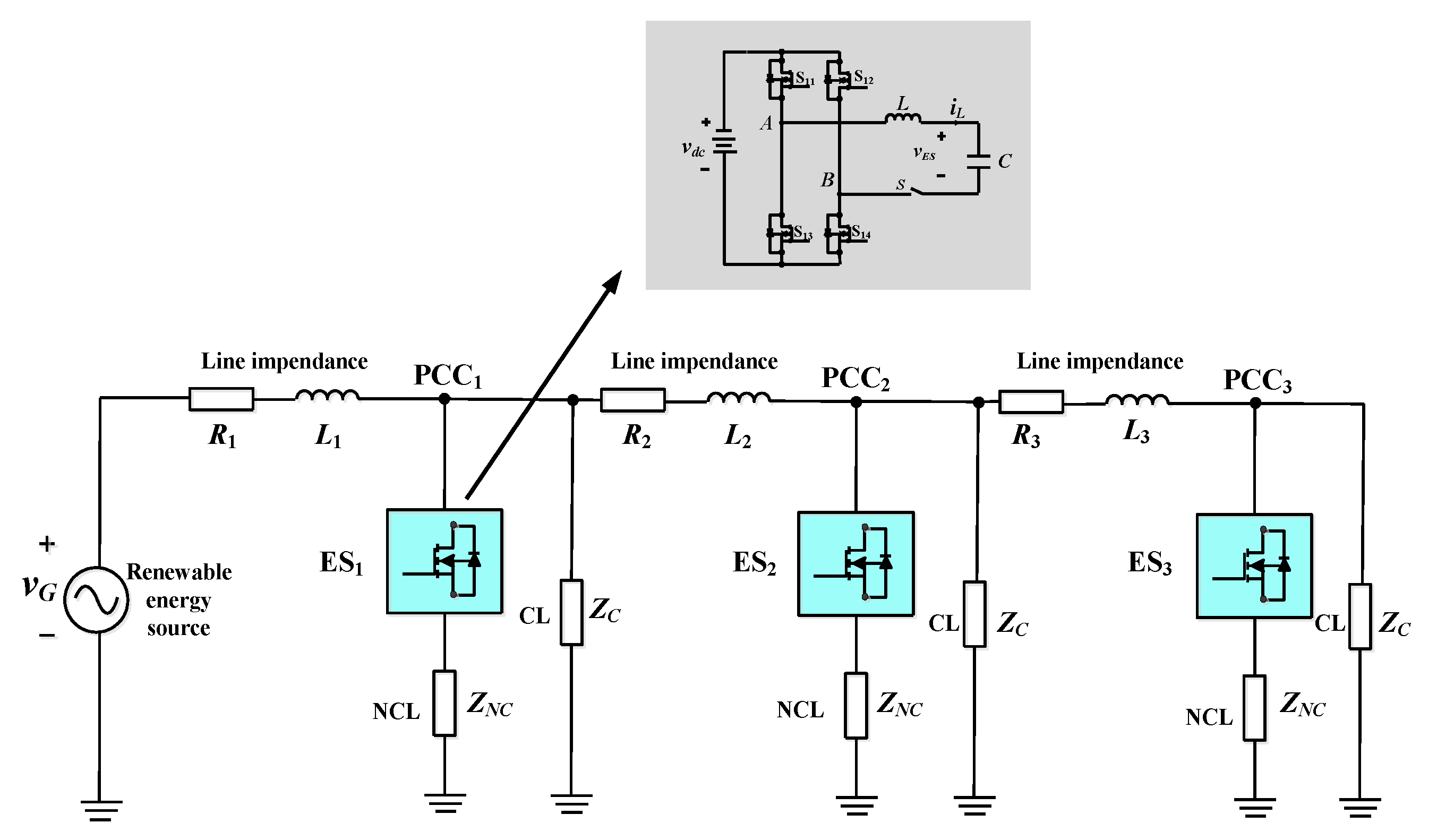
2.1. ES-2 Topology

The circuit diagram of a single-phase ES-2 is shown in Figure 2, enclosed within the dashed line. The ES is built up around an VSI whose output voltage, designated with vi, is proportional to Vdc as well as to the modulation index of VSI. The control of the ES, not shown in the figure, acts on the VSI through the delivery of the gating signals for its switches and is aimed at imposing an ES output voltage with the required values for its magnitude and phase.
In Figure 2, R 1 and L 1 denote the impedance of transmission line, and Z 2 and Z 3 denote the CL and the NCL. Moreover, v G is the equivalent voltage of the system generators. In order to make it simple and consistent with existing definitions, it is also called line voltage here. v E S represent the the ES output voltage. i G represents the current entering into the PCC, and i L and i 3 represent the currents at the VSI output and through the NCL, respectively. Lastly, v S represents the PCC voltage that coincides with the voltage across the CL.

2.2. ES-2 Model

Although the CL and the NCL can be loads of resistive, capacitive or inductive type, the CL and the NCL are here taken to be of the purely resistive type to make the ES modeling simpler. The state-space equations of ES are
{ x ˙ = A x + B u y = C x
{ x ˙ = A x + B u y = C x { x ˙ = A x + B u y = C x { x ˙ = A x + B u y = C x where, x = [ i L v E S i G ] , u = [ v G v i ] , y = [ v s ] x = [ i L v E S i G ] , u = [ v G v i ] , y = [ v s ] x = [ i L v E S i G ] , u = [ v G v i ] , y = [ v s ] x = [ i L v E S i G ] , u = [ v G v i ] , y = [ v s ] , A = [ 0 1 L f 0 1 C f 1 C f ( R 2 + R 3 ) R 2 C f ( R 2 + R 3 ) 0 R 2 L 1 ( R 2 + R 3 ) R 1 R 2 + R 1 R 3 + R 2 R 3 L 1 ( R 2 + R 3 ) ] A = [ 0 1 L f 0 1 C f 1 C f ( R 2 + R 3 ) R 2 C f ( R 2 + R 3 ) 0 R 2 L 1 ( R 2 + R 3 ) R 1 R 2 + R 1 R 3 + R 2 R 3 L 1 ( R 2 + R 3 ) ] A = [ 0 1 L f 0 1 C f 1 C f ( R 2 + R 3 ) R 2 C f ( R 2 + R 3 ) 0 R 2 L 1 ( R 2 + R 3 ) R 1 R 2 + R 1 R 3 + R 2 R 3 L 1 ( R 2 + R 3 ) ] A = [ 0 1 L f 0 1 C f 1 C f ( R 2 + R 3 ) R 2 C f ( R 2 + R 3 ) 0 R 2 L 1 ( R 2 + R 3 ) R 1 R 2 + R 1 R 3 + R 2 R 3 L 1 ( R 2 + R 3 ) ] , B = [ 0 1 L 1 0 0 1 L 1 0 ] , and C = [ 0 R 2 R 2 + R 3 R 2 R 3 R 2 + R 3 ] .
The block scheme of the ES, derived from the above equations, is drawn in Figure 3. The voltage v i is equal to d ( t ) V d c , where d(t) is the modulation signal. In modeling the ES, it is assumed that (i) the VSI modulation frequency is much higher than the fundamental frequency, (ii) the VSI dynamics are negligible, and (iii) the pair LC at the VSI output makes almost sinusoidal the quantities in the downstream circuit. It is also assumed that the amplitude of the DC voltage source is constant.

3. The Proposed Control

3.1. ES-2 Control Scheme

Primary control, also named local voltage and frequency control, provides for the independent voltage and frequency control of each ES, which belong to the outer loops. After that, the inner loops exert upon two control actions, namely the decoupled control and filter capacitor voltage control, which can be seen by the scheme in Figure 4.
In this subsection, a new type of decoupled power control is proposed for the ES. Compared to the existing power control of the ES [10], new functions are added. Specifically, a decoupling network as well as an inner current loop are added, which give the ES higher dynamic responses.
When the PCC voltage phasor v s is selected as the reference phasor, the voltage and current at the PCC can be expressed as:
v s ( t ) = 2 V s cos ( ω t )
i G ( t ) = 2 I G cos ( ω t + )
The active power (P) and reactive power (Q) at the PCC are:
P = R e ( V s I G * ) = R e ( { v s d + j v s q } · { i G d + j i G q } ) = v S d i G d + v S q i G q = v S d i G d = V s I G c o s
Q = I m ( V s I G * ) = I m ( { v s d + j v s q } · { i G d + j i G q } ) = v S d i G d v S q i G q = v S d i G d = V s I G s i n
where i G q   and i G q represent the active and reactive components of the current i G , and the last equalities hold in quasi-stationary conditions. Equations (4) and (5) show that, under the working hypothesis of a well stabilized PCC voltage, the decoupled power control is achieved by separately controlling the two current components. The relevant control scheme is drawn in Figure 4, where K and K0 are the decoupling compensation term and the feedforward coefficient of the grid voltage, respectively, and the current loops are closed by means of Proportional Integral (PI) regulators.
The effectiveness of the scheme in Figure 4 confides in the accurate control of the ES output voltage rather than of the VSI output voltage. This goal is obtained by including in the scheme an auxiliary control loop, aimed at forcing the ES output voltage to accurately track the v E S   reference signals delivered by the decoupled control stage. The auxiliary control loop, designated with ‘Filter capacitor voltage loop’ in Figure 4, is explicated in Figure 5; it contains a delay block of 1.5 T s to account for the calculation and sampling delays in the processing of the control signals. The loop controller G P R (s) is a proportional resonant (PR) regulator with the following expression:
G P R ( s ) = K p + 2 K r ω c s s 2 + 2 ω c s + ω 0 2
where, K p and K r   are the proportional and resonant parameters of the PR regulator. The PR regulator has the incomparable advantage of tracking closely a sinusoidally-shaped signal during its transients; furthermore, the amplitude gain of the PR regulator at resonant frequency can be set large enough to give the control loop an almost zero static error as well as a good anti-interference capability. Other quantities in Figure 5 are the VSI gain K P W M and the block G 2 (s), whose transfer function is:
G 2 ( s ) = ( R 1 + s L 1 ) ( R 2 + R 3 ) + R 2 R 3 s C f ( ( R 1 + s L 1 ) ( R 2 + R 3 ) + R 2 R 3 ) + R 1 + s L 1 + R 2 = Z 0 s C f Z 0 + 1
Since the response of the auxiliary control loop exhibits a weakly damped behavior, an active damping is introduced in its basic scheme by means of a complementary function that increases the damping of the ES output voltage and, with it, the stability of the control. Such a function can be obtained by feeding back -into the forward path of the v E S control- a signal representative of either the capacitor current or voltage or the inductance voltage, after an appropriate filtering. Irrespectively of the selected signal, its transduction has the inconvenience of necessitating one more sensor in the ES control hardware. However, the benefits obtained with the active damping function rewards for the additional hardware. In this paper, the feedback of the capacitor current is adopted as drawn in Figure 5, where sensing of the current is modeled by the time rate of the capacitor voltage.

3.2. The Proposed Hierarchical Control for Multiple ES-2

The current references in Figure 4 are delivered by PI regulators that close the control loops built up around the corresponding PCC voltage components. When multiple ESs are distributed along a microgrid as exemplified in Figure 1, it is no longer appropriate to use the same value (e.g., 220 V) for the voltage reference of each ES-tied node because the voltage drop inherent in the transmission line prevents the actual PCC voltage to match the reference. The consequence is that the integral term of the PI regulators of the voltage loops is subjected to the windup phenomenon. Let the accumulated voltage error be positive at a given node; the corresponding ES is forced to inject a useless active and reactive power into the SL, thus compromising its regulating action and affecting the safe operation of the other ESs. Therefore, different reference voltages must be set for ESs at different nodes, according to the droop characteristics of Figure 6.
The proposed hierarchical control determines the current components by help of a secondary control that embeds the frequency and voltage loops shown in Figure 7 within the dashed line. Both loops rely on the droop control technique. When the microgrid is running under the islanded situation, the active power flowing in the microgrid is mainly generated by the connected RESs. When an active power shortage occurs, the frequency of the microgrid declines to some extent. The tied ES compensates for the power shortage by the injection of the active power, thus improving the frequency stability of the microgrid. The stabilizing frequency action exerted by the ES allows setting of the frequency reference at the power system frequency (50Hz).
In turn, the PCC voltage is subjected to a gradual downward trend, from which it has to recover. This task is supported by the voltage control loop. Since the reactive line power Q measured at PCC is directly correlated with the voltage drop of the microgrid line, the feedback value of the voltage loop is determined by multiplying Q by the droop coefficient, expressed as:
a = 1 Q m a x 2 R 3 V 2 S a = 1 Q m a x 2 R 3 V 2 S a = 1 Q m a x 2 R 3 V 2 S a = 1 Q m a x 2 R 3 V 2 S
and by summing it to the PCC voltage. The difference between the reference voltage for the nodes and the feedback voltage is then processed by a PI regulator to give the reference of the reactive current component.

4. Simulations and Discussions

To validate the hierarchical control developed in the paper, the simulation code of multiple ESs tied to a microgrid has been worked out on the MATLAB/Simulink platform, as drawn in Figure 8. Parameters for the case study of an ES system is shown in Table 1. In the figure, switch S is set to activate or deactivate the load R from the system to realize the mismatch of the active power between the power source and the load, which will lead to the system frequency variation. The code includes a grid simulator and three ESs. The grid simulator is mainly used to emulate the voltage and frequency excursions during islanded situation. Each ES is packaged into a separate module so as to dispose of a code with plug-and-pull characteristics. The parameters of each module are set at the same value, which is convenient to enter the data for a microgrid with multiple ESs.

4.1. Single ES Control

Proper operation of the microgrid with multiple ESs rests on the correct control of a single ES. In order to examine a single ES, L 2 and L 3 are cut out from the circuit in Figure 8 and only the first ES is activated. The correctness of the control is evaluated by testing the ES behavior under voltage and frequency excursions.
Figure 9 shows the simulation results of voltage control for a single ES. The figure contains three channels, namely the predefined Root Mean Square (RMS) value of the CL voltage, the measured RMS value of the CL voltage and the RMS value of the grid voltage designated as VG. In the time interval from 0 to 0.5 s, the grid voltage is 209 V, the ES is deactivated, and the CL voltage is significantly less than the expected value of 220 V.
From 0.5 s to 1 s, the ES starts to work, and the CL voltage reaches the predefined value of 220 V gradually. Between 1–2 s and 2–3 s, the RMS value of grid voltage is steeply increased to 220 V and then to 231 V, respectively. Under the ES voltage control, after a short and restrained transient, the CL voltage quickly stabilizes at the predefined value of 220 V, ensuring the power quality of the CL supply in agreement with the requirements.
Figure 10 shows the simulation results under frequency control of a single ES. The figure has two channels, namely the predefined and measured values of frequency. At the beginning of the simulation, ES is deactivated. Due to the lack of active power, the microgrid frequency is decreased to about 49.7 Hz, which is lower than the maximum frequency excursion of ±0.2 Hz stipulated in the national standards. At 0.5 s, the ES starts to work and quickly compensates for the active power lack of the microgrid by both reducing the active power consumption of the NCL and providing active power from the ES, thus recovering the microgrid frequency at the default value of 50 Hz. At 4 s, a switch is closed to emulate a further loading of the microgrid; its active power balance is broken again and produces a consequent fall of the microgrid frequency. The ES takes an immediate action and restores the frequency to 50 Hz at 5 s. The results above are evidence of the soundness of the designed frequency control for a single ES.

4.2. Hierarchical Control of Multiple ESs

This subsection validates the effectiveness of the proposed hierarchical control by simulating the microgrid with three ESs of Figure 8 at first without any coordinated control and then by introducing the coordinated control. In the simulations, the predefined voltages at the nodes with ESs are set to 220 V.
Figure 11 reports the waveforms of the RMS value of the node voltages, and the active and reactive powers P and Q entering the nodes under the voltage control without the coordinated control. During the first 1 s-long time interval of the simulation, none of the three ESs is activated. Due to the line impedance, the CL voltages at the three PCCs greatly deviate from 220 V. At 1 s, the ES is activated. Under the action of the ESs, the CL voltages start to get closer to the predefined value of 220 V. However, as it emerges from the magnified waveforms in the central part of Figure 11(a), the three CL voltages are not able to reach the predefined value but settle on a different value. At 4 s and then at 7 s, two steeply increases of the microgrid voltage are emulated. Although the three CL voltages are close to 220 V within a certain range, they do not replicate exactly the preset value, exhibiting a steady-state error.
At 7 s, when the RMS value of the grid voltage is set to 228 V, the integral term of the voltage regulator goes saturated at 7.45 s due to the persisting voltage error, which results in a larger voltage deviation of VS1. Although VS2 and VS3 are regulated at the predefined value since the integral term of their voltage regulators do not saturate, the microgrid nodes with the tied ESs are unable, on the whole, to reach the expected steady-state operation. The simulation results confirm the shortcoming arising from the combined action of the voltage drop along the microgrid line and the gradual winding up of the integral term of the voltage regulators of some ESs. The latter ESs do no longer exert the regulating action of the node voltage, as outlined in Figure 11a, while causing a rise of the ES reactive power, as outlined in Figure 11b, which is limited by either control or device protections. This behavior is against the motivations for the usage of multiple ESs, which is intended for the existing ESs to share the microgrid fluctuations in a favorable manner.
As can be seen from the above section, it is far from enough for a single ES to ensure voltage deadness-free tracking, and it is necessary to have a coordinated control strategy to achieve reasonable setting of the reference values for multiple ESs. This section mainly carries out simulations under hierarchical control using droop control as the secondary control and power decoupling control with filter capacitor voltage control as the primary control for multiple ESs. Both voltage and frequency regulations are included.
Figure 12 shows the simulation results of reference voltage and measured voltage of ES when multiple ESs are distributed along the transmission line based on droop control. Within the first second during simulation, ES is deactivated at each PCC. In order to monitor the effectiveness of reference value change by each ES with the proposed droop control, all the reference values are initialized to 221 V. At 1 s, the ESs at the three PCC start to work and the reference voltage values of the ESs at three PCC are modified dynamically along with the sudden change of grid voltage. At the moments of 4 s and 7 s, when grid voltages are set to 220 V and 228 V respectively, it is seen that reference voltage value of each ES has been modified to new values and been tracked quickly.
Figure 13 shows the results of the three ESs under the action of the proposed control, showing the steady state and dynamic responses of the ESs under the case of grid voltage fluctuations. Figure 13a shows that the reference values of PCC voltages are different and tracked quickly with droop control. Figure 13b,c show the active and reactive power of each ES under the proposed control. It is seen that the ESs are three PCC operate at a dynamically stable state, which withstand the power fluctuation of the whole system in a harmony manner.
Finally, the frequency responses are verified with three sets of ESs by simulations, as shown in Figure 14. The figure contains two channels, namely the predefined value and the measured value of frequency. Within the first second, the ESs were not activated, and the system frequency was offset due to the imbalance between the active load and the active power supply, and thus the difference was about 0.05 Hz. At 1 s, the ESs start to work, and the active power sag of the whole system is compensated gradually due to the participation of multiple ESs, and the frequency of the system is kept stable at 50 Hz. At 5 s, the load demand in the system suddenly increases, leading to an increase in the power shortage of the system. At this time, the system frequency decreases to about 49.8 Hz, which violates the requirement that the maximum frequency deviation of the system should not exceed ±0.2 Hz. However, under the regulation of three ESs with the proposed control, the newly added active load of the system will achieve the purpose of sharing that partial active power are absorbed by the battery inside the ESs and meanwhile partial power fluctuations are passed to the NCLs. As a result, the system frequency is finally seen to stabilize at 50 Hz. The simulation verifies that the proposed control can enhance the stability of system frequency with the help of multiple ESs.

5. Conclusions

In this paper, a hierarchical control has been proposed for multiple ESs tied to a microgrid; it relies on the droop control as secondary control and on the power decoupling control as primary control. The issues of the existing solutions for operation of multiple ESs have been analyzed first, referring to the version-2 ES as the power compensation device. Proper setting of the reference value for the PCC voltages of the nodes with a tied ES has been done by the droop control technique, which has been instrumental in obtaining the coordinated operation of multiple ESs. In order to get fast and smooth ES dynamics, the performance of the power decoupling control has been improved by implementing an inner, closed-loop control of the ES output voltage, toughened with an active damping obtained by feedbacking the current flow in the ES output capacitor. To verify the effectiveness of the proposed hierarchical control together with the novel algorithms developed for its implementation, simulations are conducted to test the operation of single and multiple ESs. They have demonstrated that both node voltage and microgrid frequency are accurately and promptly regulated by the proposed control of multiple ESs with the proposed control. It should be noted that vG is difficult to measure at PCC side due to the transmission line in between. Besides, the battery management system on the ES is not focused either in this paper. Both aspects will be part of future work.

Author Contributions

Conceptualization, Q.W. and W.Z.; methodology, Q.W.; software, W.Z.; validation, W.Z., Q.W.; formal analysis, F.D.; investigation, W.Z.; resources, Q.W.; data curation, Q.W.; writing—original draft preparation, W.Z., Q.W.; writing—review and editing, Q.W., G.B.; visualization, F.D.; supervision, M.C.; project administration, Q.W.; funding acquisition, Q.W.

Funding

This work was supported by the Natural Science Foundation of Jiangsu Province under project BK20170675, and by the National Natural Science Foundation of China under project 51877040.

Acknowledgments

In this section you can acknowledge any support given which is not covered by the author contribution or funding sections. This may include administrative and technical support, or donations in kind (e.g., materials used for experiments).

Conflicts of Interest

The authors declare no conflict of interest.

References

  1. Cheng, M.; Zhu, Y. The state of the art of wind energy conversion systems and technologies: A review. Energy Convers. Manag. 2014, 88, 332–347. [Google Scholar] [CrossRef]
  2. Hu, H.; Shao, Y.; Tang, L.; Ma, J.; He, Z.; Gao, S. Overview of harmonic and resonance in railway electrification systems. IEEE Trans. Ind. Appl. 2018, 54, 5227–5245. [Google Scholar] [CrossRef]
  3. Hui, S.Y.; Lee, C.K.; Wu, F.F. Electric springs—A new smart grid technology. IEEE Trans. Smart Grid 2012, 3, 1552–1561. [Google Scholar] [CrossRef]
  4. Lee, C.K.; Chaudhuri, B.; Hui, S.Y.R. Hardware and control implementation of electric springs for stabilizing future smart grid with intermittent renewable energy sources. IEEE J. Emerg. Sel. Top. Power Electron. 2013, 1, 18–27. [Google Scholar] [CrossRef]
  5. Wang, Q.; Zha, D.; Deng, F.; Cheng, M.; Buja, G. A topology of DC electric springs for DC household applications. IET Power Electron. 2019, 12, 1241–1248. [Google Scholar] [CrossRef]
  6. Tan, S.C.; Lee, C.K.; Hui, S.Y.R. General steady-state analysis and control principle of electric springs with active and reactive power compensations. IEEE Trans. Power Electron. 2013, 28, 3958–3969. [Google Scholar] [CrossRef]
  7. Soni, J.; Panda, S.K. Electric spring for voltage and power stability and power factor correction. IEEE Trans. Ind. Appl. 2017, 53, 3871–3879. [Google Scholar] [CrossRef]
  8. Chen, X.; Hou, Y.; Tan, S.C.; Lee, C.K.; Hui, S.Y.R. Mitigating voltage and frequency fluctuation in microgrids using electric springs. IEEE Trans. Smart Grid 2015, 6, 508–515. [Google Scholar] [CrossRef]
  9. Liang, L.; Hou, Y.; Hill, D.J.; Hui, S.Y.R. Enhancing resilience of microgrids with electric springs. IEEE Trans. Smart Grid 2018, 9, 2235–2247. [Google Scholar] [CrossRef]
  10. Wang, Q.; Cheng, M.; Chen, Z. Steady-state analysis of electric springs with a novel δ control. IEEE Trans. Power Electron. 2015, 30, 7159–7169. [Google Scholar] [CrossRef]
  11. Mok, K.T.; Tan, S.C.; Hui, S.Y.R. Decoupled power angle and voltage control of electric springs. IEEE Trans. Power Electron. 2016, 31, 1216–1229. [Google Scholar] [CrossRef]
  12. Wang, Q.; Cheng, M.; Jiang, Y.; Zuo, W.; Buja, G. A Simple Active and Reactive Power Control for Applications of Single-Phase Electric Springs. IEEE Trans. Ind. Electron. 2018, 65, 6291–6300. [Google Scholar] [CrossRef]
  13. Lee, C.K.; Chaudhuri, N.R.; Chaudhuri, B. Droop control of distributed electric springs for stabilizing future power grid. IEEE Trans. Smart Grid 2013, 4, 1558–1566. [Google Scholar] [CrossRef]
  14. Chen, X.; Hou, Y.; Hui, S.Y.R. Distributed control of multiple electric springs for voltage control in Microgrid. IEEE Trans. Smart Grid 2017, 8, 1350–1359. [Google Scholar] [CrossRef]
  15. Chen, J.; Yan, S.; Yang, T.; Tan, S.C.; Hui, S.Y.R. Practical evaluation of droop and consensus control of distributed electric springs for both voltage and frequency regulation in Microgrid. IEEE Trans. Power Electron. 2019, 34, 6947–6959. [Google Scholar] [CrossRef]
  16. Chaudhuri, N.R.; Lee, C.K.; Chaudhuri, B.; Hui, S.Y.R. Dynamic modeling of electric springs. IEEE Trans. Smart Grid 2014, 5, 2450–2458. [Google Scholar] [CrossRef]
  17. Yang, T.; Liu, T.; Chen, J.; Yan, S.; Hui, S.Y.R. Dynamic modular modeling of smart loads associated with electric springs and control. IEEE Trans. Power Electron. 2018, 33, 10071–10085. [Google Scholar] [CrossRef]
  18. Luo, X.; Akhtar, Z.; Lee, C.K.; Chaudhuri, B.; Tan, S.C.; Hui, S.Y.R. Distributed voltage control with electric springs: Comparison with STATCOM. IEEE Trans. Smart Grid 2015, 6, 209–219. [Google Scholar] [CrossRef]
  19. Yang, T.; Mok, K.T.; Tan, S.C.; Lee, C.K.; Hui, S.Y.R. Electric springs with coordinated battery management for reducing voltage and frequency fluctuations in microgrids. IEEE Trans. Smart Grid 2018, 9, 1943–1952. [Google Scholar] [CrossRef]
  20. Wang, M.; Yang, T.; Tan, S.C.; Hui, S.Y.R. Hybrid electric springs for grid-tied power control and storage reduction in AC microgrids. IEEE Trans. Power Electron. 2019, 34, 3214–3225. [Google Scholar] [CrossRef]
  21. Yang, Y.; Ho, S.S.; Tan, S.C.; Hui, S.Y.R. Small-signal model and stability of electric springs in power grids. IEEE Trans. Smart Grid 2018, 9, 857–865. [Google Scholar] [CrossRef]
  22. Bevrani, H.; Shokoohi, S. An intelligent droop control for simultaneous voltage and frequency regulation in islanded microgrids. IEEE Trans. Smart Grid 2013, 4, 1505–1513. [Google Scholar] [CrossRef]
  23. Liu, J.; Miura, Y.; Ise, T. Comparison of dynamic characteristics between virtual synchronous generator and droop control in inverter-based distributed generators. IEEE Trans. Power Electron. 2016, 31, 3600–3611. [Google Scholar] [CrossRef]
  24. Mahmood, H.; Michaelson, D.; Jiang, J. Reactive power sharing in islanded microgrids using adaptive voltage droop control. IEEE Trans. Smart Grid 2015, 6, 3052–3060. [Google Scholar] [CrossRef]
  25. Guerrero, J.M.; Vasquez, J.C.; Matas, J.; Vicuna, L.G.; Castilla, M. Hierarchical control of droop-controlled AC and DC microgrids—A general approach toward standardization. IEEE Trans. Ind. Electron. 2011, 58, 158–172. [Google Scholar] [CrossRef]
  26. Tinajero, G.A.; Aldana, N.L.D.; Luna, A.C.; Ramirez, J.S.; Cruz, N.V.; Guerrero, J.M.; Vasquez, J.C. Extended-optimal-power-flow-based hierarchical control for islanded AC microgrids. IEEE Trans. Power Electron. 2019, 34, 840–848. [Google Scholar] [CrossRef]
Figure 1. Microgrid with three ES-2 (electric springs (ES) exchanging both active and reactive power with the smart load (SL) branch to stabilize the critical load (CL) voltage and frequency).
Energies 12 03511 g001
Figure 2. ES-2 circuit diagram.
Energies 12 03511 g002
Figure 3. ES-2 block scheme.
Energies 12 03511 g003
Figure 4. Current loops of primary control for ES-2.
Energies 12 03511 g004
Figure 5. ES output voltage control.
Energies 12 03511 g005
Figure 6. Droop characteristics for different node voltages.
Energies 12 03511 g006
Figure 7. Proposed hierarchical control for ES-2.
Energies 12 03511 g007
Figure 8. MATLAB/Simulink platform for microgrid with three ES-2.
Energies 12 03511 g008
Figure 9. Simulation results of voltage control for a single ES.
Energies 12 03511 g009
Figure 10. Simulation results of frequency control for a single ES.
Energies 12 03511 g010
Figure 11. Simulation results of multiple ESs operating without coordinated control: (a) RMS value of point of common coupling (PCC) voltage; (b) active power; (c) reactive power.
Energies 12 03511 g011aEnergies 12 03511 g011b
Figure 12. Reference versus measured voltages with the proposed control of multiple ESs.
Energies 12 03511 g012
Figure 13. Simulation results of multiple ESs operating with the proposed control: (a) RMS value of PCC voltage; (b) active power; (c) reactive power.
Energies 12 03511 g013aEnergies 12 03511 g013b
Figure 14. Simulation results of frequency responses with three ESs under the proposed control.
Energies 12 03511 g014
Table 1. Parameters for the case study of an ES system.
ParameterValues
Line 1resistance (R1)0.3 Ω
Line 1 inductance (L1)5 mH
Line 2resistance (R2)0.2 Ω
Line 2 inductance (L2)1.2 mH
Line 3resistance (R3)0.2 Ω
Line 3 inductance (L3)1.2 mH
Critical load 1(RC1)180 Ω
Non-critical load 1(RNC1)40 Ω
Critical load 2(RC2)100 Ω
Non-critical load 2(RNC2)60 Ω
Critical load 3(RC3)100 Ω
Non-critical load 3(RNC3)60 Ω
filter Inductance (L)2.3 mH
filter Capacitance (C)26 µF
PCC voltage (VS)220 V
DC bus voltage (Vdc)400 V
Switching frequency (f)20 kHz

