Characterization of Core-Shell Spherical Lens for Microtracking Concentrator Photovoltaic System


Abstract
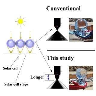
1. Introduction
2. Configuration of the SMTCPV System
3. Simulation
3.1. CSSP Lenses Characteristics for Monochromatic Light without Lens Material Absorption
3.2. CSSP Lenses Characteristics for Full Solar Spectrum Without Lens Material Absorption
3.3. CSSP Lenses Characteristics for Full Solar Spectrum with Lens Material Absorption
4. Experiment
4.1. Visual Comparison
4.2. Outdoor Experiment
5. Conclusions
Author Contributions
Funding
Conflicts of Interest
References
- Dimroth, D.F. New World Record for Solar Cell Efficiency at 46%—French-German Cooperation Confirms Competitive Advantage of European Photovoltaic Industry. Available online: https://www.ise.fraunhofer.de/en/press-media/press-releases/2014/new-world-record-for-solar-cell-efficiency-at-46-percent.html (accessed on 11 September 2019).
- Steiner, M.; Bösch, A.; Dilger, A.; Dimroth, F.; Dörsam, T.; Muller, M.; Hornung, T.; Siefer, G.; Wiesenfarth, M.; Bett, A.W. FLATCON® CPV module with 36.7% efficiency equipped with four-junction solar cells. Prog. Photovolt. Res. Appl. 2015, 23, 1323–1329. [Google Scholar] [CrossRef]
- Apostoleris, H.; Stefancich, M.; Chiesa, M. Tracking-integrated systems for concentrating photovoltaics. Nat. Energy 2016, 1, 16018. [Google Scholar] [CrossRef]
- Duerr, F.; Meuret, Y.; Thienpont, H. Tailored free-form optics with movement to integrate tracking in concentrating photovoltaics. Opt. Express 2013, 21, A401–A411. [Google Scholar] [CrossRef]
- Zagolla, V.; Dominé, D.; Tremblay, E.; Moser, C. Self-tracking solar concentrator with an acceptance angle of 32°. Opt. Express 2014, 22, A1880–A1894. [Google Scholar] [CrossRef]
- Ma, H.; Wu, L. Horizontally staggered lightguide solar concentrator with lateral displacement tracking for high concentration applications. Appl. Opt. 2015, 54, 6217–6223. [Google Scholar] [CrossRef]
- Michel, C.; Blain, P.; Clermont, L.; Languy, F.; Lenaerts, C.; Fleury-Frenette, K.; Décultot, M.; Habraken, S.; Vandormael, D.; Cloots, R.; et al. Waveguide solar concentrator design with spectrally separated light. Sol. Energy 2017, 157, 1005–1016. [Google Scholar] [CrossRef][Green Version]
- Hallas, J.M.; Baker, K.A.; Karp, J.H.; Tremblay, E.J.; Ford, J.E. Two-axis solar tracking accomplished through small lateral translations. Appl. Opt. 2012, 51, 6117–6124. [Google Scholar] [CrossRef]
- Dhakal, R.; Lee, J.; Kim, J. Bio-inspired thin and flat solar concentrator for efficient, wide acceptance angle light collection. Appl. Opt. 2014, 53, 306–315. [Google Scholar] [CrossRef]
- Karp, J.H.; Tremblay, E.J.; Hallas, J.M.; Ford, J.E. Orthogonal and secondary concentration in planar micro-optic solar collectors. Opt. Express 2011, 19, A673–A685. [Google Scholar] [CrossRef]
- Bouchard, S.; Thibault, S. Planar waveguide concentrator used with a single axis tracker. Opt. Express 2014, 51, 6848–6854. [Google Scholar] [CrossRef]
- Price, J.S.; Sheng, X.; Meulblok, B.M.; Rogers, J.A.; Giebink, N.C. Wide-angle planar microtracking for quasi-static microcell concentrating photovoltaics. Nat. Commun. 2015, 6, 6223. [Google Scholar] [CrossRef]
- Lloyd, J.; Pavilonis, M.; Gladden, C.; Casper, C.; Schneider, K.; McMahon, W. Performance of a prototype stationary catadioptric concentrating photovoltaic module. Opt. Express 2018, 26, A413–A419. [Google Scholar] [CrossRef]
- Vu, N.; Shin, S. Flat Concentrator Photovoltaic System with Lateral Displacement Tracking for Residential Rooftops. Energies 2018, 11, 114. [Google Scholar] [CrossRef]
- Ito, A.; Sato, D.; Yamada, N. Optical design and demonstration of microtracking CPV module with bi-convex aspheric lens array. Opt. Express 2018, 26, A879–A891. [Google Scholar] [CrossRef]
- Schrank, H.; Sanford, J. A Luneberg-Lens Update. IEEE Antennas Propag. Mag. 1995, 37, 76–79. [Google Scholar]
- Morgan, S.P. General solution of the Luneberg lens problem. J. Appl. Phys. 1958, 29, 1358–1368. [Google Scholar] [CrossRef]
- Kotsidas, P.; Modi, V.; Gordon, J.M. Realizable planar gradient-index solar lenses. Opt. Lett. 2012, 37, 1235–1237. [Google Scholar] [CrossRef]
- Dodge, M.J. Refractive properties of magnesium fluoride. Appl. Opt. 1984, 23, 1980–1985. [Google Scholar] [CrossRef]
- Liu, Z.; Yang, S.; Nie, Z. A dielectric lens antenna design by using the effective medium theories. In Proceedings of the 2010 International Symposium on Intelligent Signal Processing Communication Systems, Chengdu, China, 6–8 December 2010; pp. 1–4. [Google Scholar]
- Xi, J.Q.; Schubert, M.F.; Kim, J.K.; Schubert, E.F.; Chen, M.; Lin, S.Y.; Liu, W.; Smart, J.A. Optical thin-film materials with low refractive index for broadband elimination of Fresnel reflection. Nat. Photonics 2007, 1, 176–179. [Google Scholar] [CrossRef]
- Tabata, M.; Adachi, I.; Ishii, Y.; Kawai, H.; Sumiyoshi, T.; Yokogawa, H. Development of transparent silica aerogel over a wide range of densities. Nucl. Instrum. Methods Phys. Res. A 2010, 623, 339–341. [Google Scholar] [CrossRef]
- Nakatani, M.; Yamada, N. Optical Simulation of Two-Shell Spherical Lens for Microtracking CPV System. In Proceedings of the IEEE 7th World Conference on Photovoltaic Energy Conversion, Waikoloa, HI, USA, 10–15 June 2018; pp. 927–930. [Google Scholar]
- Rhys, T.L. The Design of Radially Symmetric Lenses. IEEE Trans. Antennas Propag. 1970, 18, 497–506. [Google Scholar] [CrossRef]
- Kotsidas, P.; Modi, V.; Gordon, J.M. Nominally stationary high-concentration solar optics by gradient-index lenses. Opt. Express 2011, 19, 2325–2334. [Google Scholar] [CrossRef]
- Shin-Etsu-Chemical Silicone Fluid Catalog Shin-Etsu Chemical Catalog. Available online: http://www.shinetsusilicone-global.com/catalog/pdf/fluid_e.pdf (accessed on 11 September 2019).
- Sultanova, N.; Kasarova, S.; Nikolov, I. Dispersion properties of optical polymers. Acta Phys. Pol. A 2009, 116, 585–587. [Google Scholar] [CrossRef]
- Cooper, P.R. Refractive-index measurements of paraffin, a silicone elastomer, and an epoxy resin over the 500–1500-nm spectral range. Appl. Opt. 1982, 21, 3413–3415. [Google Scholar] [CrossRef]
- New Energy and Industrial Technology Development (NEDO), Solar Spectrol Database VER-3 2018. Available online: https://www.nedo.go.jp/library/nissharyou.html (accessed on 11 September 2019).


| Parameters | PMMA Homogenous Spherical Lens | KF-96-500cs Homogeneous Spherical Lens | CSSP Lens |
|---|---|---|---|
| Shell refractive index (RI), nshell | 1.491 @ 589 nm | 1.403 @ 589 nm | 1.491 @ 589 nm |
| Core RI, ncore | N/A | N/A | 1.403 @ 589 nm |
| Shell radius, rshell | 15 mm | 15 mm | 15 mm |
| Core radius, rcore | N/A | N/A | 10.2 mm (0.68 × rshell) |
| Geometrical concentration ratio, C | 6.25× for Figure 8a 100× for Figure 8b and Figure 9 | ||
| Ray spectrum | Sodium D line (589 nm) | ||
| Absorption by lens materials | Ignored | ||
| Required | Reason | KF-96-500cs [26] |
|---|---|---|
| Low refractive index | For long focal length | 1.403 @ 589 nm |
| Liquid in ambient | Solid material tends to cause a separation at core-shell interface | Liquid |
| Low volatile matter content | No bubble formation | max 0.5% at 150 °C/24 h |
| Cauchy Coefficients | Values |
|---|---|
| α0 | 1.389 |
| α2 | 0.005296 |
| α4 | −0.00018 |
| CSSP Lens Simulation Specifications | |
|---|---|
| Shell RI, nshell | Wavelength dispersion of PMMA is considered |
| Core RI, ncore | Wavelength dispersion of KF-96-500cs is considered |
| Shell radius, rshell | 15 mm |
| Core radius, rcore | 10.2 mm (0.68 × rshell) |
| Geometrical concentration ratio, C | 100× |
| Ray spectrum | AM1.5D standard solar spectrum Top subcell range: 280–749 nm Middle subcell range: 750–949 nm Bottom subcell range: 950–2000 nm Full range: 280–2000 nm |
| Absorption by lens materials | Ignored |
| Parameters | PMMA Homogeneous Lens | KF-96-500cs Homogeneous Lens | Cssp Lens |
|---|---|---|---|
| Top subcell range | 74.7% | 72.9% | 79.8% |
| Middle subcell range | 75.2% | 73.5% | 79.4% |
| Bottom subcell range | 75.0% | 72.4% | 79.2% |
| Full range | 74.4% | 71.5% | 79.3% |
| CSSP Lens Simulation Specifications | |
|---|---|
| Shell RI, nshell | Wavelength dispersion of PMMA is considered |
| Core RI, ncore | Wavelength dispersion of KF-96-500cs is considered |
| Shell radius, rshell | 1, 5, 10, 15 mm |
| Core radius, rcore | 0.68 × rshell |
| Geometrical concentration ratio, C | 6.25× for Figure 12a 100× for Figure 12b |
| Ray spectrum | AM1.5D standard solar spectrum Full range: 280–2000 nm |
| Absorption by lens materials | Spectral transmittance of lens materials is considered |
© 2019 by the authors. Licensee MDPI, Basel, Switzerland. This article is an open access article distributed under the terms and conditions of the Creative Commons Attribution (CC BY) license (http://creativecommons.org/licenses/by/4.0/).
Share and Cite
Nakatani, M.; Yamada, N. Characterization of Core-Shell Spherical Lens for Microtracking Concentrator Photovoltaic System. Energies 2019, 12, 3517. https://doi.org/10.3390/en12183517
Nakatani M, Yamada N. Characterization of Core-Shell Spherical Lens for Microtracking Concentrator Photovoltaic System. Energies. 2019; 12(18):3517. https://doi.org/10.3390/en12183517
Chicago/Turabian StyleNakatani, Masakazu, and Noboru Yamada. 2019. "Characterization of Core-Shell Spherical Lens for Microtracking Concentrator Photovoltaic System" Energies 12, no. 18: 3517. https://doi.org/10.3390/en12183517
APA StyleNakatani, M., & Yamada, N. (2019). Characterization of Core-Shell Spherical Lens for Microtracking Concentrator Photovoltaic System. Energies, 12(18), 3517. https://doi.org/10.3390/en12183517