1. Introduction
Interplanetary exploration and deep space activities have attracted enormous attention over the past several decades. However, these projects are expensive even for developed countries or mature space technology organizations. Also, long-term space explorations impose many challenges and risks to astronauts, who suffer more cosmic ray exposure and bone loss. Therefore, a new, trustworthy technique is in great demand to reduce the mission duration, risk, and cost for future space exploration [
1,
2,
3]. The nuclear thermal propulsion (NTP) system is a promising technology, which uses nuclear fission energy rather than the traditional chemical reactions to heat liquid hydrogen [
4,
5], thus its specific impulse shows significant improvement over chemical rockets due to the lower molecular weight of propellant. The specific impulse represents the efficiency of the rocket engines. More specifically, it is the change in momentum per unit mass for fuels, or rather how much more push accumulates as the fuel is used [
6]. Increasing the specific impulse means less propellant is used for same mission or a heavier payload is achieved at the same propellant consumption [
7]. Furthermore, NTP has a higher thrust (even up to 100 tons) and a longer lifetime than any other current in-space propulsion systems, which ensures a faster transmit procedure and longer traveling distance on space missions [
8,
9]. Because of its excellent transportation performance, NTP broadens the launch window of space missions (to months instead of days) [
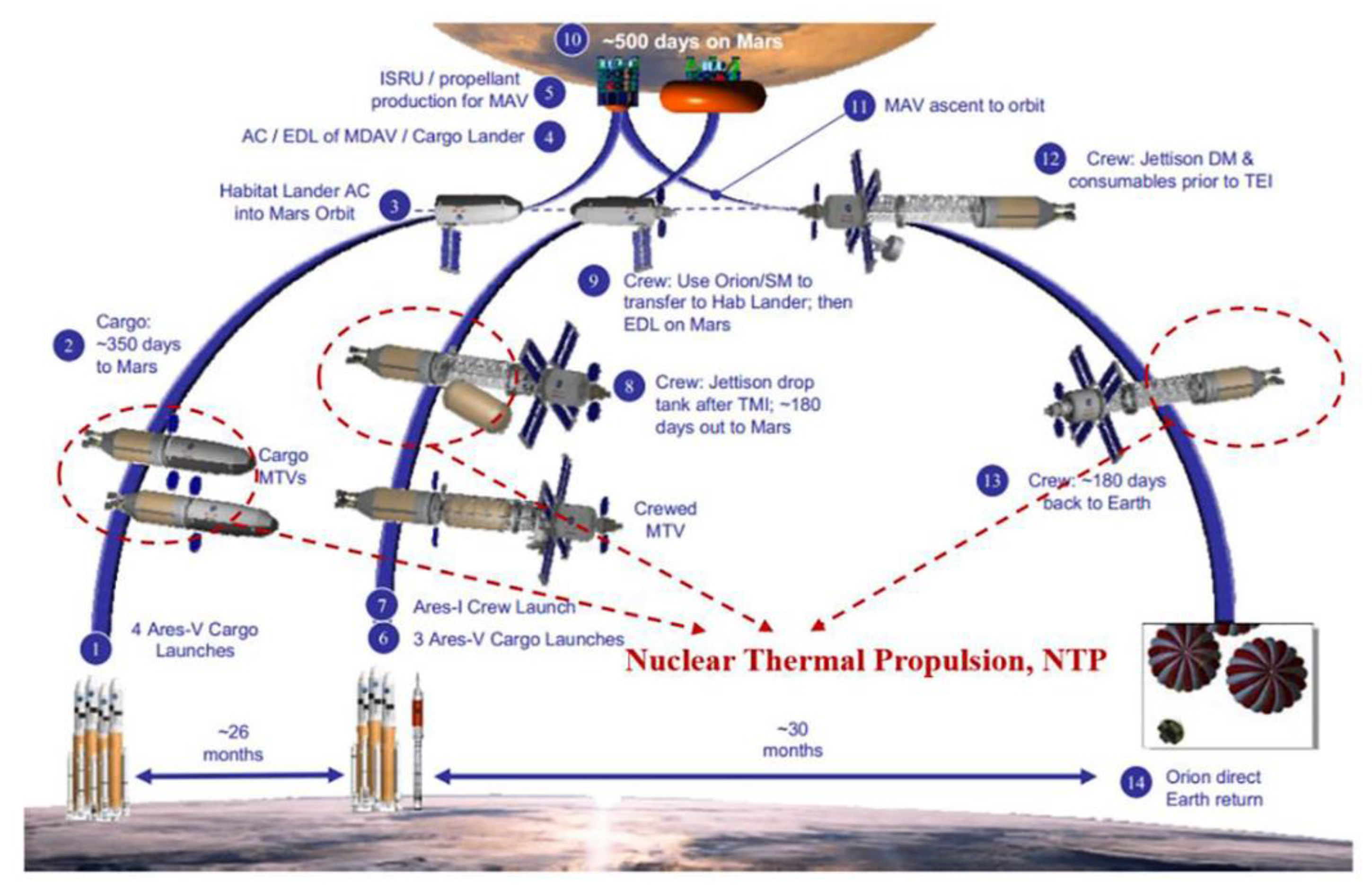
10], and is capable of returning to Earth at any time within three months of Earth departure burn, which increases the mission robustness and allows for potential abort scenarios. National Aeronautics and Space Administration (NASA) has anticipated that NTP could be the preferred option in outer space, especially for manned Mars exploration activities programmed in the Mars Design Reference Architecture 5.0 (DRA 5.0) in 2009 [
11], as shown in
Figure 1. In this sequence, the NTP system will be equipped on the cargo Mars transfer vehicles (MTVs) and crewed MTV. It will also be applied to the return journey of the crew to Earth. According to the architecture, the initial mass in low earth orbit (IMLEO) reduces by 33%, while the traveling time in space decreases by 40% when using NTP instead of a conventional chemical stage [
10].
NTP has been studied for several decades. It was first conceived in 1940s and 1950s, and aggressively developed in the 1960s and the early 1970s. The principal research was carried out in the United States of America (USA) and the Union of Soviet Socialist Republics (USSR) [
12]. In the USA, the most representative effort is the “Rover” project and the later Nuclear Engine for Rocket Engine Application (NERVA) [
13]. During the projects, more than 20 different reactors were built, and numerous key technologies, including fuel fabrication and testing, were realized. The projects demonstrated that NTP could be a feasible and reliable tool to explore space, and the latest NERVA engine, the XE, was qualified for a human mission to Mars. Meanwhile, the USSR claimed to build the most developed prototype nuclear engine, RD-0410, which had a slightly better performance than NERVA. Regrettably, no nuclear thermal propulsion system has been launched into space yet. The NERVA project was terminated in 1973 due to non-technical reasons, but research still proceeded in some institutions. In the 1980s, a more efficient, compact, and lightweight design, namely the particle bed reactor (PBR), was proposed based on the knowledge derived from NERVA, which further enhanced exploration capabilities [
14]. However, PBR is much more immature than NERVA in terms of the technology due to many inherent technical challenges.
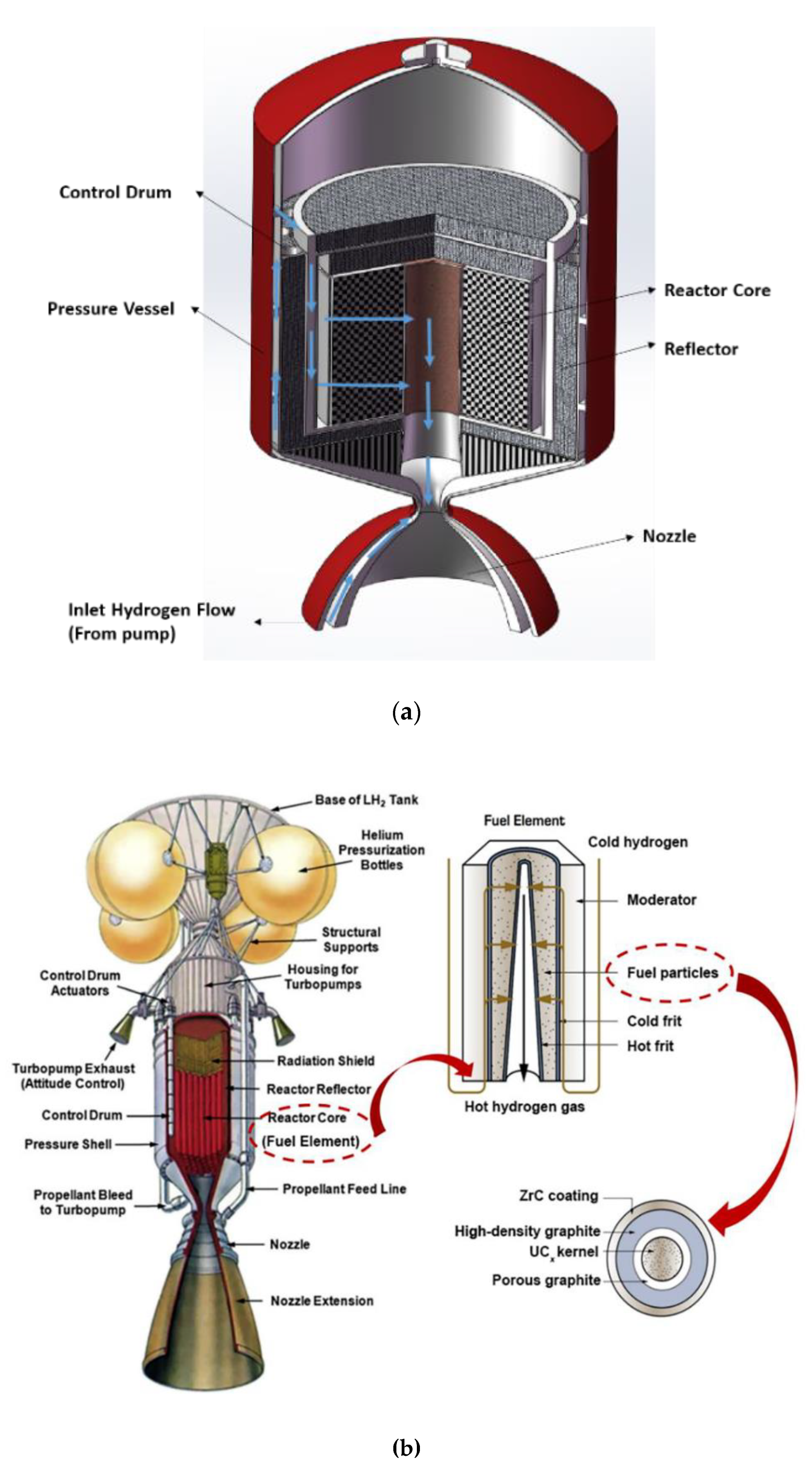
A typical PBR mainly consists of a reactor core, a shield, a control system, a liquid hydrogen (LH
2) tank, a turbo-pump, and a nozzle, and it can be divided into two types according to the core layout, i.e., individual PBR (
Figure 2a) and fuel elements-assembled PBR (
Figure 2b). In the individual PBR, fuel pebbles (particles) are packed randomly in an annular region between two orifices called cold frit and hot frit, respectively. In the fuel elements-assembled PBR, the size of the fuel particles is reduced to that of a grain of sand and the thickness of the fuel region decreases as well; together with the moderator base, a hexagonal fuel element is formed, and several similar elements are assembled to form the core. When the propulsion system runs, cryogenic hydrogen is extracted from the liquid tank and pumped up to a higher pressure. After that, the pressurized hydrogen is preheated by cooling the regenerative channel of the nozzle, the reactor reflector, the control drums, and other important components. Subsequently, a portion of the preheated hydrogen expands in the turbo to drive the pump and the exhausted hydrogen flows into the reactor core. In the core, the coolant flows radially inward to the particle bed to cool the fuel particles, and then flows axially toward the thrust chamber through a hot gas channel. Finally, the high-temperature coolant is ejected from a convergent–divergent nozzle to generate thrust [
15]. The partial flow path of the hydrogen is shown in
Figure 2.
The particles increase the interfacial heat transfer area between the fuel and the coolant, which enhances the heat transfer capability in PBR. Thus, the power density of the reactor core is raised to an extremely high level, even more than 40 MW/L in the fuel elements, which requires an excellent thermal hydraulic design to avoid the hot spot. However, the flow distribution of coolant in the core is a challenging issue. In PBR, especially in the fuel elements-assembled PBR, the coolant is reasonably distributed among the fuel elements first, and then the coolant is distributed along the axis to match the heat-release profile in each fuel element. The first part does not present a problem, as the flow distribution occurs in the prism-type reactor and can be directly achieved by using orifices. The second part is more difficult, and there are only a few pieces of research that have reported the relative information.
Morley et al. [
16] investigated the flow distribution in a critical pellet (pebble) bed reactor using an in-house code, NUTHAM-S, which is based on a two-dimensional thermal hydraulic model for calculating pressure, flow, and temperature. According to their findings, the hot frit contributed to control the amount of coolant flowing in any particular region of the reactor core, while the cold frit was inefficient in the distribution of flow through the core. Hence, the porosity profile on the hot frit was optimized to make the axial temperature in the region adjacent to the hot frit as uniform as possible. However, in another thermal hydraulic analysis performed by Benenati et al. [
17], the conclusion was drawn that the cold frit porosity was an important factor which significantly affected the flow distribution in the core. Moreover, they also found that the hot gas channel diameter majorly affected the convective heat transfer process in the core. Tuddenham [
18] developed a code to investigate the flow distribution and the thermal hydraulic characteristics in a fuel element of a packed bed nuclear reactor, where the cold frit was designated to control the coolant flow. They observed some significant axial flow in the fuel region, which led to a great variation in temperature along the hot gas channel. Ludwig et al. [
14] presented a detailed introduction of three fuel elements-assembled PBRs, which consisted of 19, 37, and 61 fuel elements, respectively. In their work, the flow distribution in the fuel elements was mainly realized by the cold frit. It was also addressed that an optimized porosity profile on the cold frit was beneficial in terms of a better thermal hydraulic design, which was demonstrated through the work performed by Ji et al. [
19], where the non-dominated sorting genetic algorithm with elitisms approach (NSGA-II) was adopted to optimize the porosity profile on the cold frit; the thermal performance was exactly improved after this optimization.
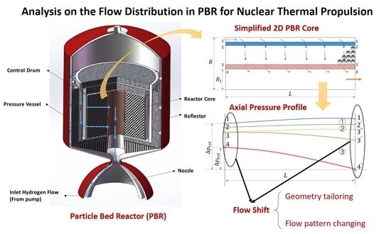
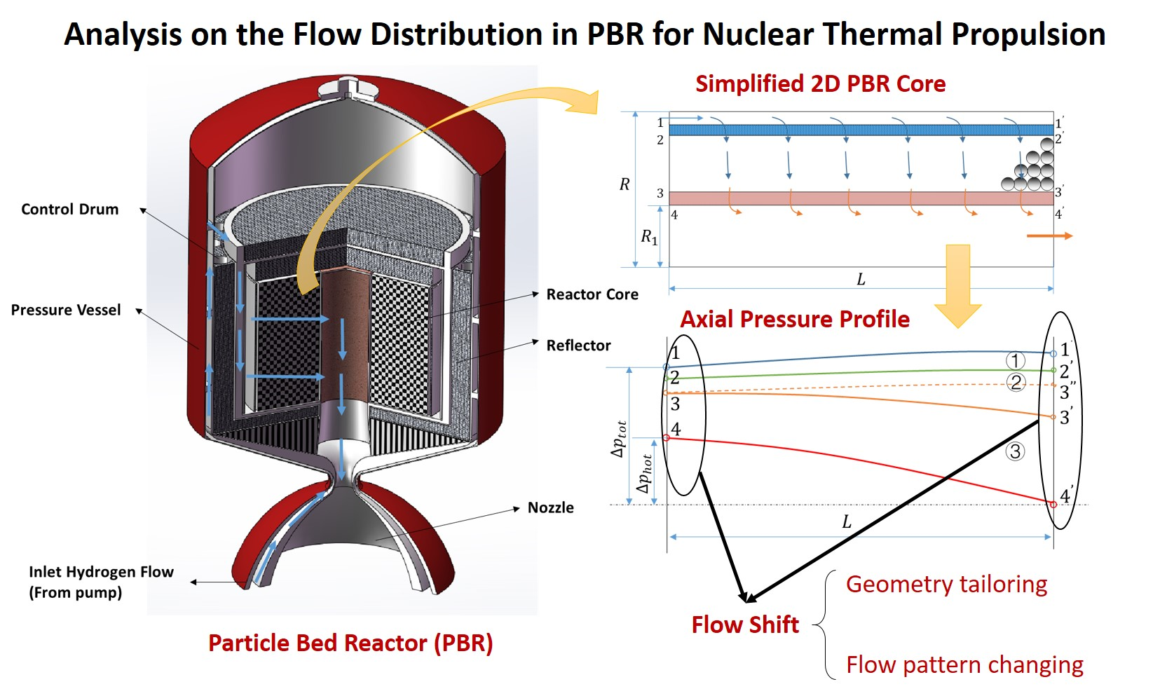
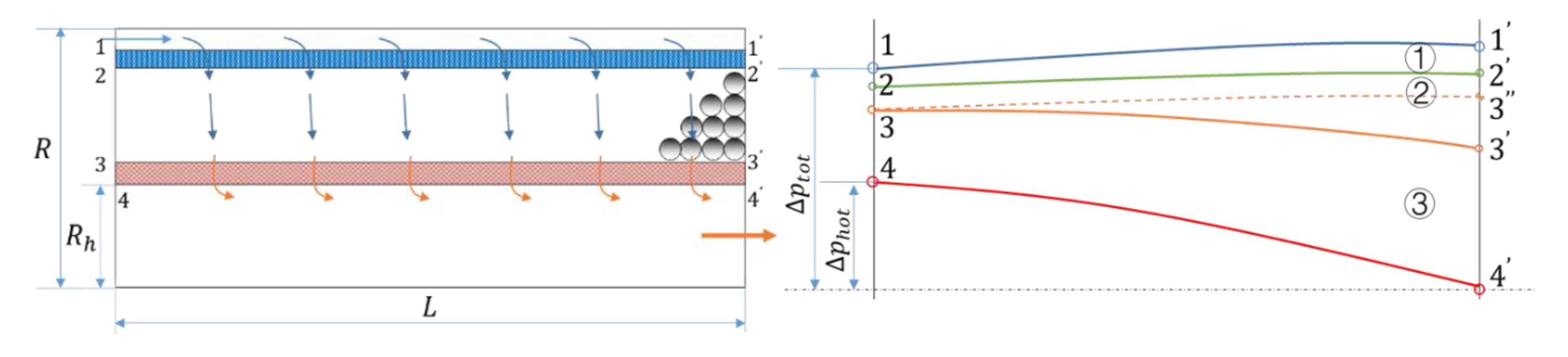
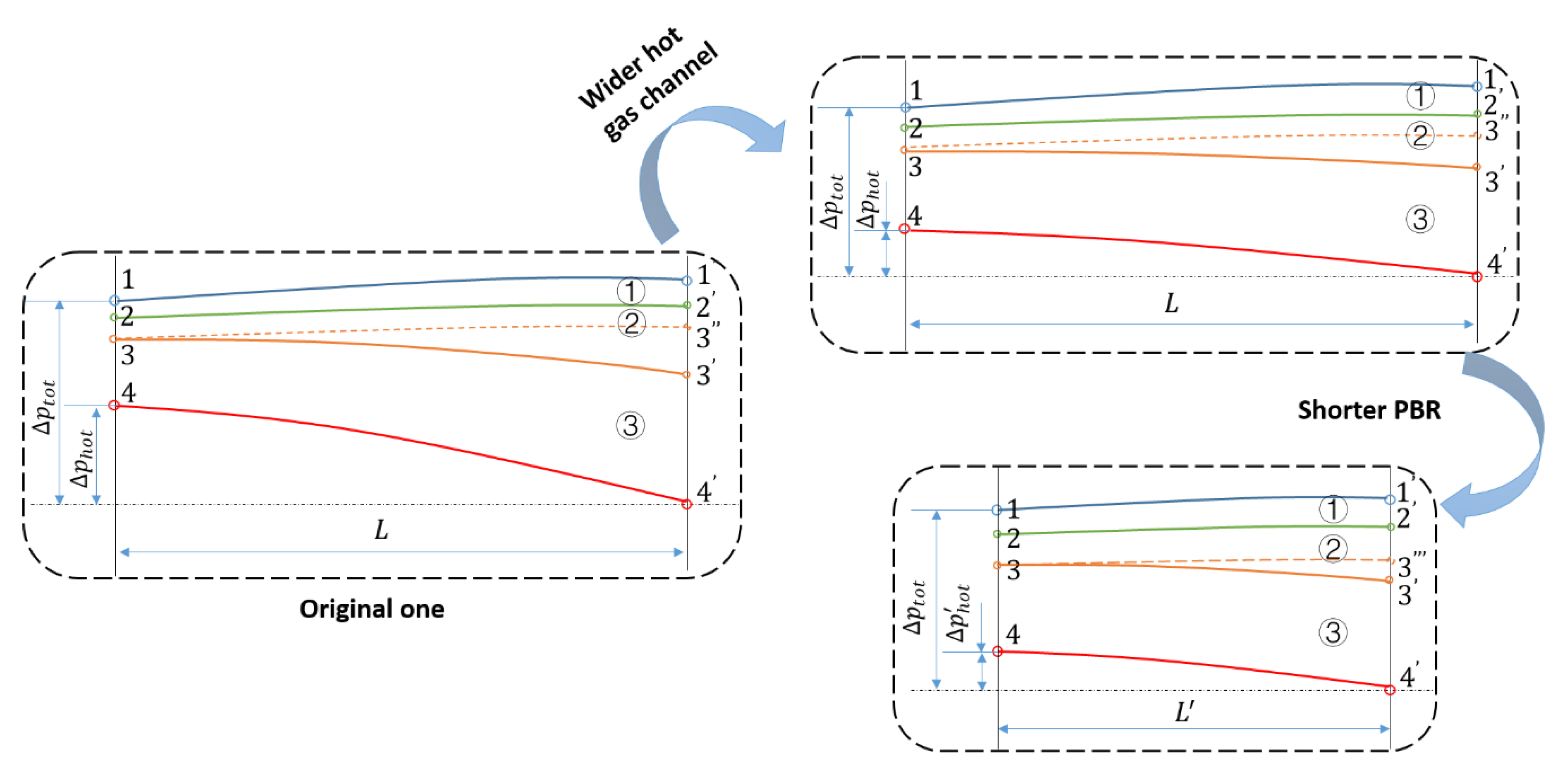
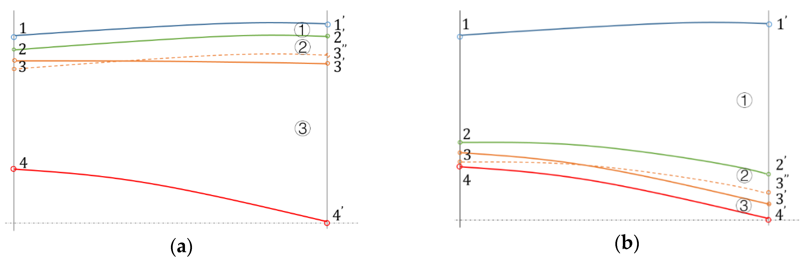
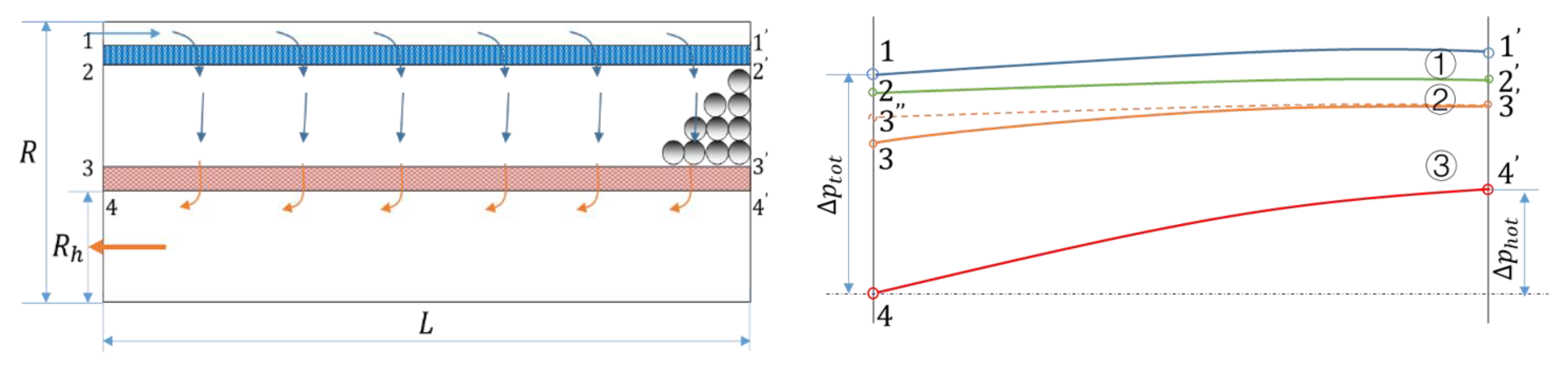
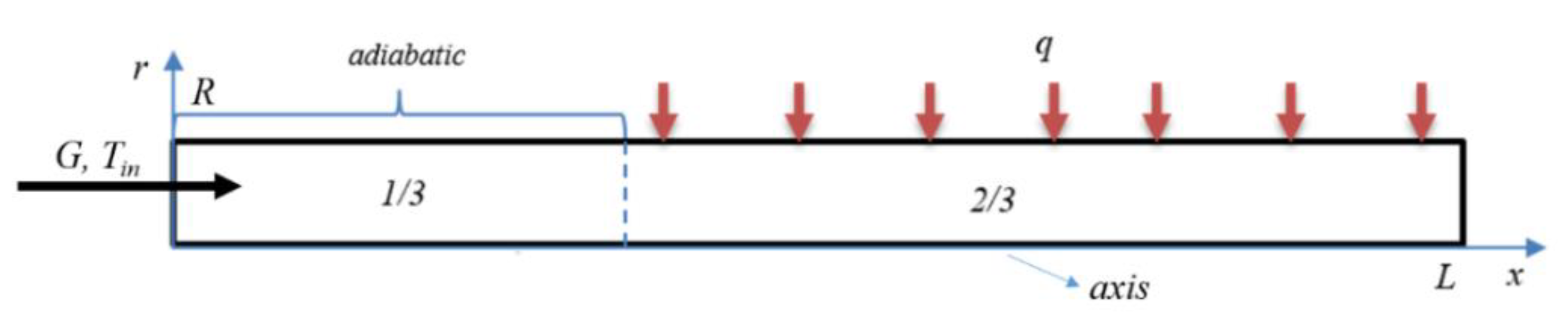
From the literature review above, it is noted that there was no consensus regarding the use of cold frit or hot frit to control coolant flow. In addition, the effects of other factors on the flow distribution have not been discussed yet. Therefore, in this paper, the typical axial pressure profile of a dummy PBR was analyzed, based on which, the flow distribution was studied and several approaches, including decreasing the pressure drop within the hot gas channel, increasing the pressure drop across the cold or hot frits, and changing the flow pattern, were proposed to improve the flow distribution and reduce temperature mal-distribution in the PBR core. Moreover, the pros and cons of using cold frit or hot frit for flow distribution were also analyzed. Following this, a computational model was developed and some numerical examples were applied to verify the analyses.
4. Conclusions and Further Considerations
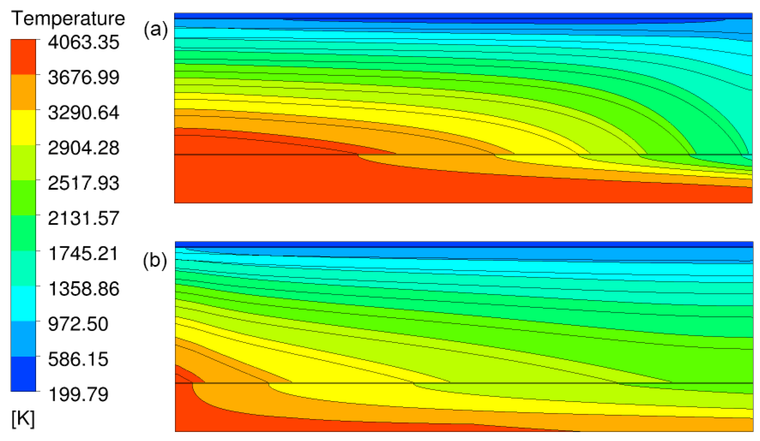
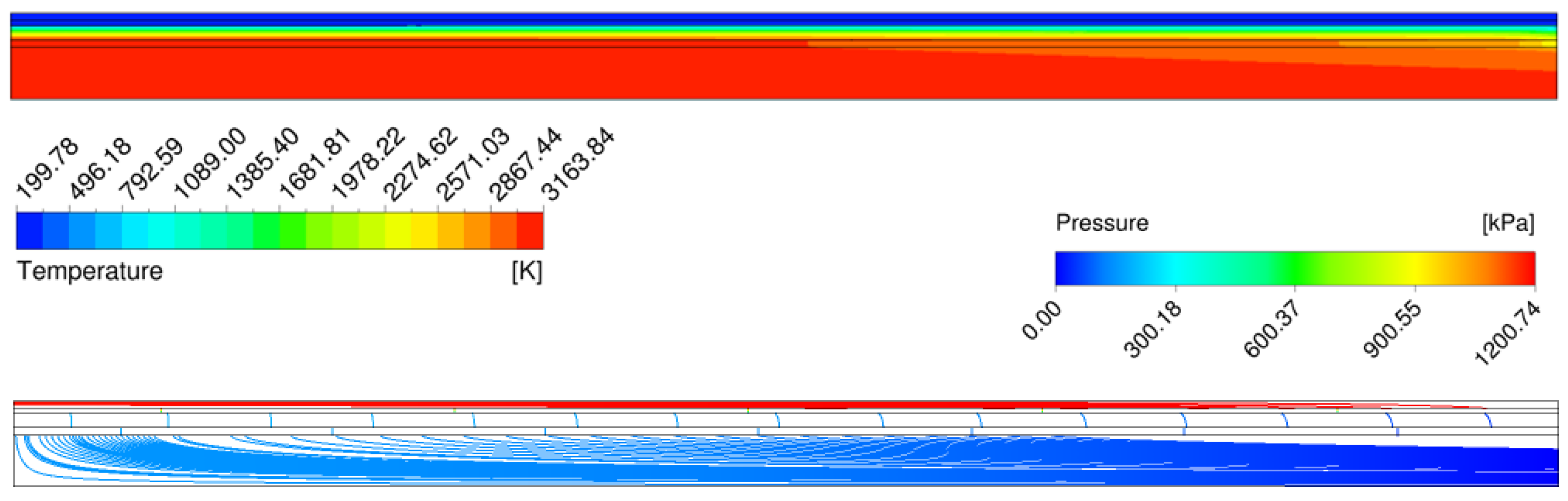
The particle bed reactor (PBR) is the most efficient, compact, and lightweight method among all current nuclear thermal propulsion (NTP) concepts, but the thermal hydraulic design is a challenging issue, where the flow distribution of coolant is an important component. Based on the understanding of the axial pressure profile in the PBR core, this paper thoroughly analyzed the flow process of coolant in a dummy design. The analyses revealed that more coolant always flows toward one side in this dummy PBR, which was called a “flow shift” phenomenon. This phenomenon was mainly caused by a significant pressure drop within the hot gas channel and led to a hot spot in the core. The stronger the flow shift was, the higher the maximum temperature in the core was. Three approaches, i.e., decreasing the pressure drop in the hot gas channel directly, increasing the resistance of cold or hot frits to reduce the percentage of pressure drop within the hot gas channel accounting for the total pressure drop, and changing the flow pattern from a “Z” to a “U” pattern were proposed to reduce flow shift. In particular, the pros and cons of using a cold frit-dominated design or a hot frit-dominated design were discussed. To restrict flow redistribution and avoid flow instability, the use cold frit is recommended in PBRs of high power density, while the use hot frit is recommended in PBRs of relatively low density to distribute the coolant. All analyses were demonstrated by numerical simulations.
Overall, this work is beneficial to understanding of the flow distribution in PBRs. However, these qualitative analyses are only part of the puzzle. In future work, more studies emphasizing the quantitative relationship of these geometry parameters, power density, and flow variables should be performed. In addition, almost all of work presented here was based on uniform heat release, hence, further analyses should be carried out based on the non-uniform power profile.


