Article

Dynamic Stall of a Vertical-Axis Wind Turbine and Its Control Using Plasma Actuation

Key Laboratory of Power Station Energy Transfer Conversion and System, Ministry of Education, North China Electric Power University, Beijing 102206, China
*
Author to whom correspondence should be addressed.
Energies 2019, 12(19), 3738; https://doi.org/10.3390/en12193738
Submission received: 27 August 2019 / Revised: 25 September 2019 / Accepted: 26 September 2019 / Published: 30 September 2019
(This article belongs to the Special Issue Wind Turbine Power Optimization Technology)

Abstract

:
In this paper, a dynamic stall control scheme for vertical-axis wind turbine (VAWT) based on pulsed dielectric-barrier-discharge (DBD) plasma actuation is proposed using computational fluid dynamics (CFD). The trend of the wind turbine power coefficient with the tip speed ratio is verified, and the numerical simulation can describe the typical dynamic stall process of the H-type VAWT. The tangential force coefficient and vorticity contours of the blade are compared, and the regular pattern of the VAWT dynamic stall under different tip speed ratios is obtained. Based on the understanding the dynamic stall phenomenon in flow field, the effect of the azimuth of the plasma actuation on the VAWT power is studied. The results show that the azimuth interval of the dynamic stall is approximately 60° or 80° by the different tip speed ratio. The pulsed plasma actuation can suppress dynamic stall. The actuation is optimally applied for the azimuthal position of 60° to 120°.

Graphical Abstract

1. Introduction

Dielectric-barrier-discharge (DBD) plasma actuation is an active flow control technology developed in the mid-1960s [1]. The actuator is a plasma-generating device, which is composed of two electrodes, dielectric between the electrodes, and an external high voltage power source. When the actuator is working, the air near the electrode is ionized to ions and electrons. Due to the asymmetry of the electrode arrangement, the ions move in an orientated direction within the electric field, generating a body force that drives the neutral gas molecules to produce a tangential jet, achieving boundary layer flow control. DBD plasma actuation has good performance in boundary layer flow separation control [2], dynamic stall vortex control [3], and so on [4].
The dynamic stall phenomenon can be removed by unsteady pitch control of the blade and the boundary layer separation [5]. Dynamic stall is an inherent feature of VAWT. The angle of attack and relative speed of a blade are changing dramatically during each VAWT rotation cycle. The boundary layer separates and a leading edge vortex is formed on the suction side. This causes the VAWT dynamic stall. Dynamic stall will bring about VAWT structure vibration, noise, and efficiency reduction [6]. VAWT dynamic stall is a complex unsteady flow phenomenon. When the blade moves, the relative velocity and direction are time varying, and the blade is affected by the upstream wake. Although researchers are extremely interested in using flow control methods to improve wind turbine performance [7,8,9,10], few researchers have addressed the problem of VAWT dynamic stall. Previous works have only focused on the relationship between the lift/drag and the angle of attack [11], or simply flow field [12,13]. However, there is still a need for investigating the correspondence between the vortex motion and the tangential force of a blade.
There is a considerable amount of research on plasma dynamic stall control for an oscillating airfoil or a flat plate. There is still little knowledge about plasma control of VAWT. In 2006, Post & Corke [3] placed the actuator at the leading edge of NACA0015 airfoil, and the effect of DBD plasma for flow separation and dynamic stall control on an oscillating airfoil was studied experimentally. It was found that the plasma actuation was able to suppress separation and delay stall, and the pulsed actuation was more advantageous. Sato et al. [14] studied the lift enhancement of an oscillating plate by plasma actuation through wind tunnel experiments and numerical simulations. They pointed out that plasma actuation could effectively suppress the flow separation on the flat plate during the up-stroke motion. Phan & Shin [15] using numerical method investigated the impact on the aerodynamic performance at different plasma actuation parameters and actuation positions for an oscillating NACA0012 airfoil. They believed that plasma could increase the lift of the airfoil and suggested to consider the energy consumption of the actuator to achieve the optimal control authority. Greenblatt et al. [16,17] placed a plasma actuator on the leading edge of a small vertical-axis wind turbine and conducted related research. The actuator is placed at the leading edge in a pulsed actuation mode. The results showed that after applying control, the power of the wind turbine increased and the fluctuation decreased, because plasma actuation reduced the leading edge vortex. They also argued that plasma actuation is only effective on the upwind side; however, it was not clear what specific azimuthal interval should be applied actuation. It is valuable and practical to formulate a scientific and economic control strategy to reduce the excited energy consumption and increase the power of the wind turbine.
Two methods can be used to study dynamic stall phenomena: numerical methods [18,19] and wind tunnel experimental methods [20]. Due to the complexity of the VAWT dynamic stall phenomenon, wind tunnel experiments are difficult to capture the full detailed flow field. Therefore, the numerical simulation method is used to study the VAWT dynamic stall problem. The load of VAWT can be calculated using the empirical formula model [21] and the theoretical model [22]. The former is calculated formula fitted by the experimental data, which is easy to implement and low in cost; the latter is mainly solved by the CFD method, and a complex flow field with high kinetic energy and shearing can be obtained, but its more time consuming. Buchner et al. [23] used a theoretical model to study the dynamic stall phenomenon of VAWT and found that the tip speed ratio was less than 3, which significantly reduced the power of VAWT. Most of the dynamic stall effects occur in the low tip speed ratio (less than 3), while the VAWTs actually operate mainly within it, which highlights the industrial relevance of the dynamic stall problem.
A suitable actuator simplified model needs to be selected for numerical simulation of DBD plasma flow control. Shyy et al. [24], Massines et al. [25], Suzen et al. [26], and Abdollahzadeh et al. [27,28,29] proposed their actuator simplified models based on different assumptions, respectively. The most widely used is the phenomenological model proposed by Shyy et al., which loads the plasma reduced body force into the fluid momentum equation as a source term. The advantages of the Shyy’s model are simplicity, fast response, ease of application, and so on. However, the oversimplified model severely overestimates the body forces generated by the plasma actuator. Therefore, the experimental correction of the Shyy’s model must be performed before the numerical calculation. The following literature use the corrected Shyy’s model for numerical simulation studies [30,31]. Considering the complex unsteadiness of the VAWT dynamic stall and the accuracy of the phenomenological model, in this paper, the modified Shyy’s model is selected for numerical simulation.
In this paper, the unsteady CFD method is used to study the dynamic stall phenomenon of VAWT at different tip speed ratios, and the azimuthal position corresponding to the start and end of dynamic stall is found. The modified plasma phenomenological model is used to analyze the influence of plasma actuation on VAWT in different azimuthal intervals. An optimal control strategy for dynamic stall of a vertical-axis wind turbine based on plasma actuation is proposed.

2. Computational Model and Numerical Method

2.1. H-Type VAWT Model

In this paper, a two-dimensional model is used for numerical simulation. The three-blade H-type VAWT model computational domain is shown in Figure 1, which is consistent with the reference [22,32]. D represents the diameter of the wind turbine. Inlet, outlet, upper, and lower boundary are 2.5D, 4.5D, and 2D from the VAWT center, respectively.
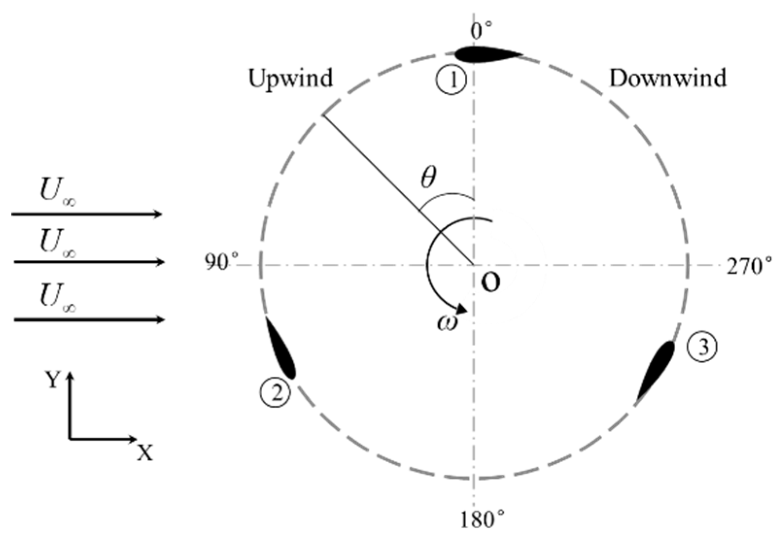
The radius of VAWT is R = 0.3 m. The blade adopts the NACA0022 airfoil with a chord length c = 0.1 m. The inlet velocity is U = 5.07 m/s. The rotational speed ω = 16.9~50.7 rad/s, are studied, corresponding to the tip speed ratio λ = 1 to 3. θ is the azimuth, and the position where the blade 1 is located in Figure 2 is defined as θ = 0°. θ = 0°~180° is the upwind side, and θ = 180°~360° is the downwind side.
The plasma actuator is placed at 5~90% c from the leading edge, and the purple triangle represents the plasma region (The actuator is placed at 30% c), as shown in Figure 3.

2.2. Plasma Actuator Model

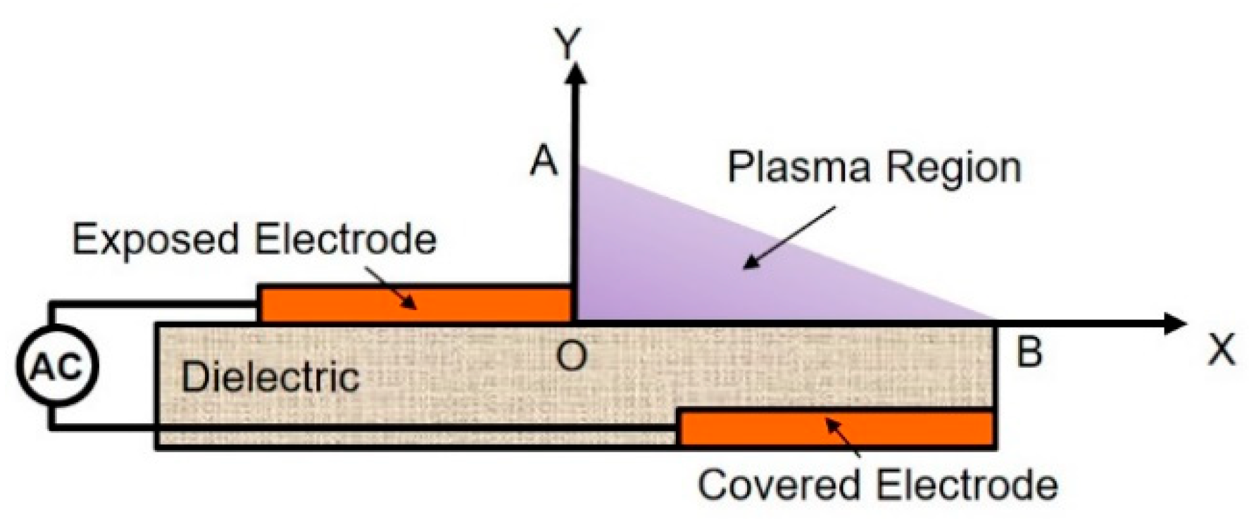
The Shyy’s model [24] simplifies the complex body force generated by plasma into linear electric field force. The basic mechanism of the actuator is shown in Figure 4.
Ignoring the secondary factors, assuming that the plasma density ρc is constant and the electric field is linearly distributed, the electric field distribution in the OAB is obtained as
| E | = E 0   k 1 x     k 2 y
where E0 = 1.2 × 10⁴ kV/m is the maximum electric field strength, and the coefficients k1 = 1.8 × 10⁹ kV/m2 and k2 = 3.6 × 10⁹ kV/m2 are obtained from the electric field distribution [30].
The body force induced by the plasma actuator can be expressed as electric field force
F = E ρ c e α
where e = 1.602 × 10⁻¹⁹ C [24] is elementary charge, and ρc = 1 × 10¹⁷ m3 [24]. The α = 0.3 is the correction factor [30].
The duty cycle is: Dtc = Td/T, where Td is the duration of the plasma actuation and T is the period.
The original Shyy’s model is a great oversimplification; hence, the model used in this paper is calibrated by experiment [33]. In the present study, the height and width of the plasma region in Figure 4 are OA = 2.5 mm and OB = 5 mm [34,35]. In Equation (2), The electric field strength is multiplied by the correction factor of 0.3. Figure 5 is the comparison between the computational and experimental [33] streamwise velocity distribution, where up is the plasma reduced velocity, and up,max = 5.9 m/s is the maximum plasma reduced velocity. The ordinate represents the distance from the wall. It can be seen from Figure 5 that the corrected model has a good agreement with the experimental values.

2.3. Numerical Method and Boundary Conditions

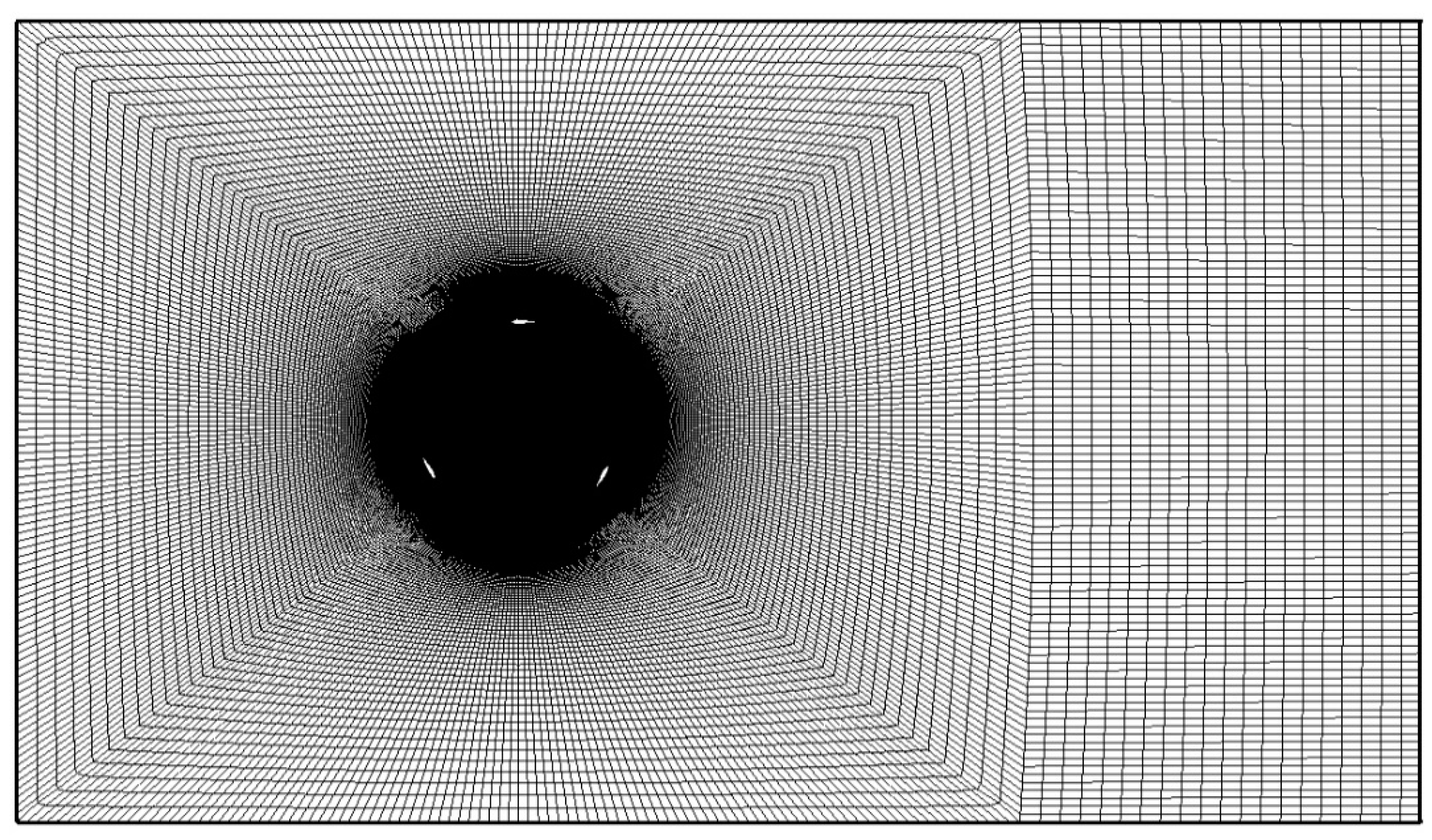
Figure 6 shows the global mesh of the computational domain. The structured grid is generated, and the total number of cells is 300,000. The sliding mesh is used to establish the rotation domain and the number of cells is 260,000. The grids number along the circumference of a blade is 500. The first cell height of the blade is 0.01 mm, which guarantees y+ < 1, as shown in Figure 7.
Inlet is velocity inlet. Outlet is pressure outlet. Upper and lower boundary are symmetry. The blade surface is a non-slip wall. The electric field force generated by the plasma actuation is loaded as a body force source term though the user-defined function.
Numerical simulations are calculated using ANSYS FLUENT. The turbulence model is k-ω SST model. The blades rotate 0.2 degrees per time step.

2.4. CFD Validation

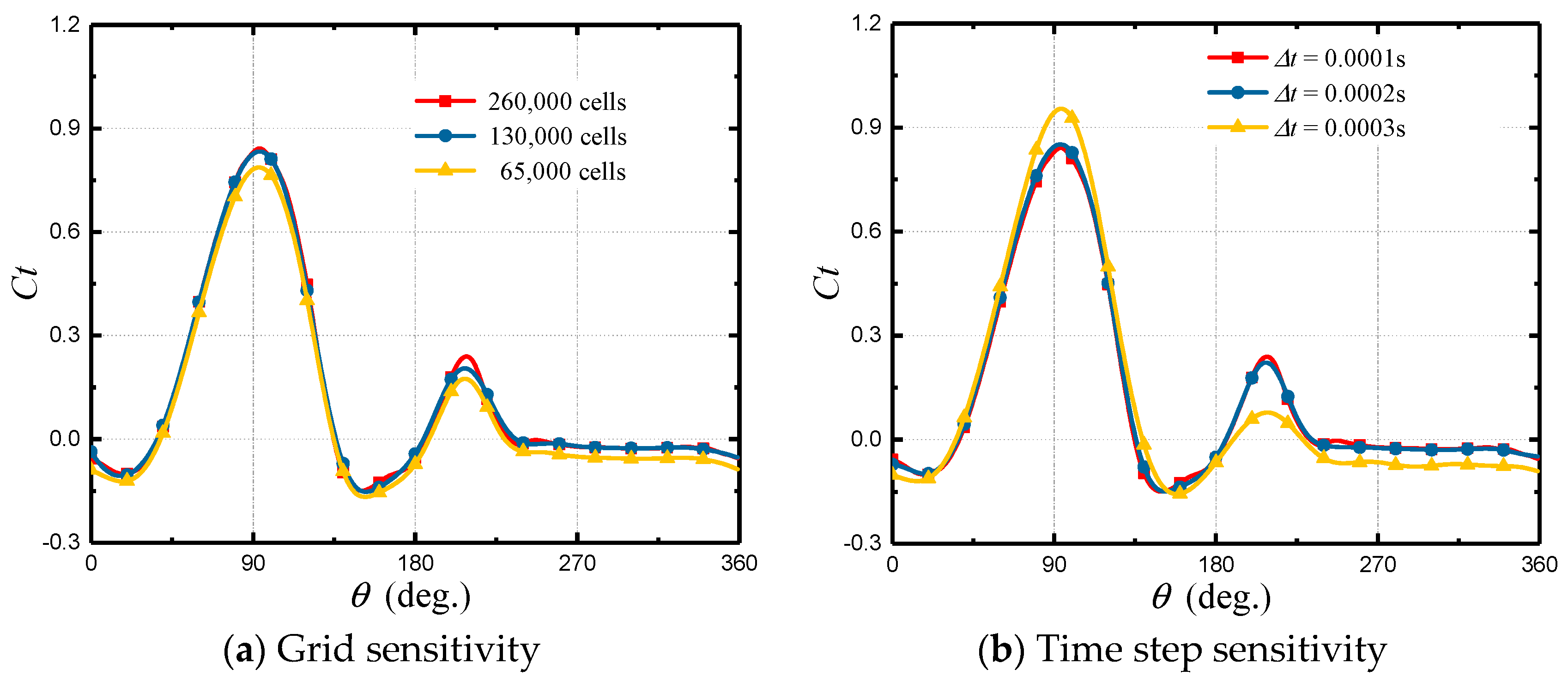
In Figure 8a, grid sensitivity verification is performed on base-line case (U = 5.07 m/s, λ = 2.15) of three different numbers of cells. As a constant, the first cell height of the blade is 0.01 mm, which guarantees y+ < 1. The grids number along the circumference of a blade are 500, 250, and 125, respectively. As can be seen from the figure, the difference between the three grids is small. Considering the requirements of the plasma model for the grid, the fine mesh (260,000 cells) is selected.
VAWT dynamic stall is a complex unsteady flow phenomenon; hence, the time step sensitivity verification is necessary. Figure 8b shows the verification of three different the time step sizes on base-line case. It can be seen that large time step size (Δt = 0.0003 s) makes the tangential force larger. Since the frequency of the plasma pulsed actuation is high, the minimum time step size is selected. When the time step size is Δt = 0.0001 s, the blades rotate 0.2 degrees per time step.
It is important and necessary to choose a suitable turbulence model for numerical simulation. A large number of scholars [36,37,38,39] have used k-ω SST model to solve VAWT problems. Therefore, this paper does not perform additional verification on the turbulence model.
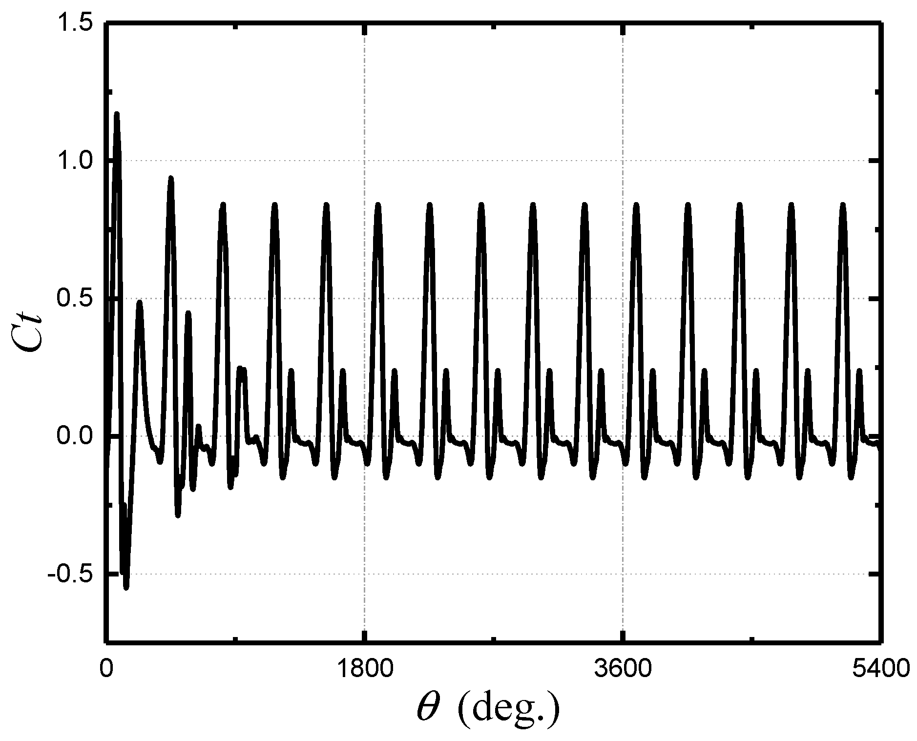
The convergence criterions are that all the parameters was set to 10–4 at each time step and the tangential force coefficient of a blade exhibits significant periodicity. Figure 9 shows the variation of the tangential force coefficient with azimuth over 15 cycles. As can be seen from the Figure 9, the solution of the last 10 cycles have converged. In this paper, we use the time average result of the last 10 cycles.

2.5. H-Type VAWT Aerodynamic Parameters

Several major aerodynamic parameters are described below to characterize VAWT dynamic stall.
The tip speed ratio λ is the blade linear velocity to the free stream velocity U, which is used to describe the blades’ rotation speed. It is defined as
λ = R Ω / U
where R is the radius of the rotor and Ω is the angular velocity of the rotor.
The relative velocity ratio U ^ r e l is the instantaneous relative velocity of the blade Urel to the free stream velocity. It is defined as
U ^ r e l = U r e l U
The angle of attack based on the instantaneous relative velocity is
α r e l = tan 1 ( sin θ λ + cos θ )
The αrel varying with azimuth is shown in the Figure 10. It can be seen that the lower the tip speed ratio, the larger the amplitude of αrel.
The tangential force coefficient Ct and the power coefficient Cp represent the ability of the blade and the rotor to generate energy, respectively.
The tangential force coefficient is defined as
C t = F t 1 / 2 ρ U 2 S
where Ft is tangential force of a blade, and S is the maximum projected area of a blade.
The power coefficient is defined as
C p = 3 F t λ 1 / 2 ρ U 2 A
where A is the frontal projected area of wind turbine.

2.6. Parameter Settings

The research scheme is shown in Table 1. In Scheme 1, the VAWT dynamic stall at five different tip speed ratios is studied. On the basis of Scheme 1, taking λ = 2.15 as an example, given the actuation duty cycle, and the pulse actuation frequency f, the effects of five plasma actuator positions on VAWT are investigated. In Scheme 3, given the plasma actuator position, the effects of 10 plasma actuation intervals on VAWT dynamic stall are studied.

3. Results and Discussion

3.1. Computational Results Verification

Figure 11 shows the comparison of the experimental data [32] and the two-dimensional numerical simulation data for wind turbine power coefficient. It can be found that the simulation results of both Zuo et al. [22] and this paper can reflect the variation tendency of Cp, but the numerical values are always larger than the experimental values. Because the two-dimensional numerical simulations ignore the end loss of the three-dimensional blades [40] and the influence of the support structure. Reference [40] pointed out that the two-dimensional URANS simulation can capture most of the details for the VAWT flow field. This paper mainly studies the flow separation and control technology on the VAWT, so the two-dimensional URANS simulation is adopted.

3.2. Influence of Tip Speed Ratio

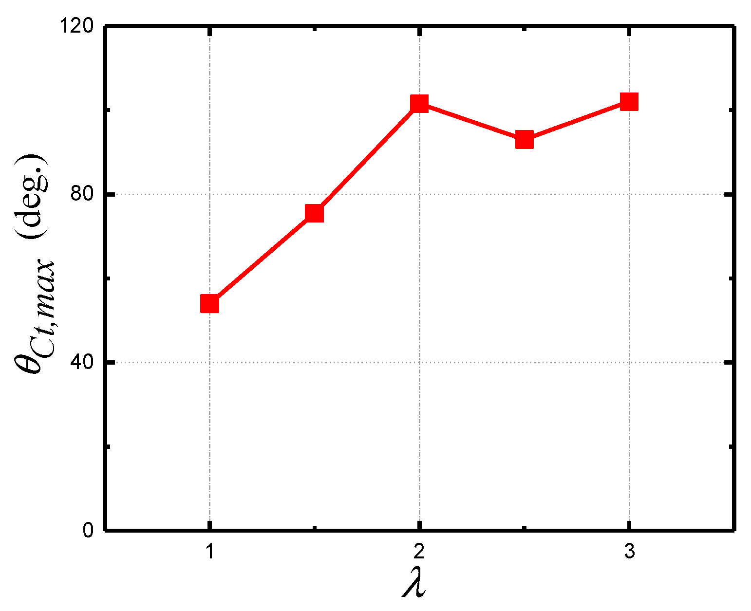
Five tip speed ratios, λ = 1, 1.5, 2, 2.5, and 3, were investigated. Figure 12 shows the variation of the blade tangential force coefficient Ct with azimuth at different tip speed ratios. In a rotation cycle, the Ct basically exhibits a double-peak variation. The maximum tangential force coefficient Ct max and its corresponding azimuth θct.max, with increasing tip speed ratio, increase first and then remain unchanged. It can be seen that when the blade moves to the downwind side, the Ct value is around 0 due to the influence of the upstream wakes.
In [20], the VAWT consists of NACA0015 airfoil, which is a thin thickness airfoil. The dynamic stall phenomenon of this kind of wind turbine is expressed as the formation, development and shedding of the leading edge vortex on the blade or airfoil. The VAWT selected in this paper consists of the NACA0022 airfoil, which is a medium thickness airfoil. In [41], the aerodynamic performance of the four VAWT airfoils (NACA0012, NACA0022, NACA5522, and LS0421) was compared. The study found that the NACA0022 airfoil performs better at small tip speed ratios. The dynamic stall phenomenon is not exactly the same as the above literature. The main difference is that there is not only the leading edge vortex on the blade, but also a trailing edge vortex with the same direction of rotation.
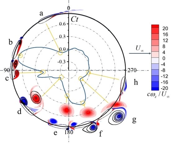
Figure 13 shows the vorticity (normalized to z/U) contour at specific azimuths for blade 1 during a cycle at λ = 1.5. For ease of understanding, the correspondence between vortex and Ct is indicated by arrows. It should be pointed out that only under this condition, the dynamic stall occurs twice, which is represented by two distinct peaks on the Ct curve, which is the same as the case studied in [11]. The first dynamic stall has gone through four stages a, b, c, and d. The α at point a is small, resulting in a minor Ct. As the angle of attack increases with azimuth, Ct increases significantly. The azimuth of point b corresponds to the maximum of Ct, in which the flow separation from the trailing edge almost rolls up to the leading edge. It can be considered that the movement process of the blade in range a to b is in keeping with the static stall feature. At azimuth c, a leading edge vortex appears, and the vortex adheres to the surface and keep on growing. Under the influence of the leading edge vortex and the non-slip wall condition, a secondary vortex whose rotation direction is opposite to the leading edge vortex is formed. Point d is the minimum of Ct. At this time, the leading-edge vortex extends to one chord length above the suction side, while the boundary layer rolls up and forms a trailing edge vortex close to the surface. Those two vortices interact with each other and obtain circulation in the shear layer to strengthen the vorticity. After that, the leading edge vortex and the trailing edge vortex gradually shed off, and the boundary layer reattaches to the leading edge. The first dynamic stall ends. At the same time, the second dynamic stall occurs on the downwind side. The four typical moments (e, f, g, and h) correspond to the formation, development, and shedding of the leading-edge vortex, and the reattachment of the boundary layer at leading edge. Different from the upwind-side dynamic stall, the trailing edge vortex on the downwind side is not formed on the surface, which is affected by the free flow below the rotor. In this figure, the trajectories of the leading edge vortex and the trailing edge vortex on the upwind and the downwind side can also be observed.
Figure 14 shows the vorticity (normalized to z/U) contours of the blade 1 for selected azimuth at different tip speed ratios. The major vortex structure and its motion state can be clearly observed. The development and their interaction of the leading edge vortex and a pair of trailing edge vortices can be found out. Comparing the vorticity contours, we can see the delay effect of the VAWT dynamic stall at high tip speed ratio. The delay effect means that as the tip speed ratio rises, the VAWT dynamic stall is delayed. The higher the tip speed ratio, the smaller the amplitude of the angle of attack and the relative speed, and the less evidently the dynamic stall occurs.
Figure 15 shows the vorticity contours for different tip speed ratios at θ = 120°. In order to facilitate the observation and comparison, the coordinates of the blade are transformed. Although the blades rotate to the same azimuth, the vorticity contours are totally different. It can be considered that these five vorticity fields (from λ = 3 to λ = 1) can represent the VAWT dynamic stall at different stages. At the same azimuth, the high tip speed ratio corresponds to a small angle of attack, and the dynamic stall delay is more distinct at high tip speed ratios.
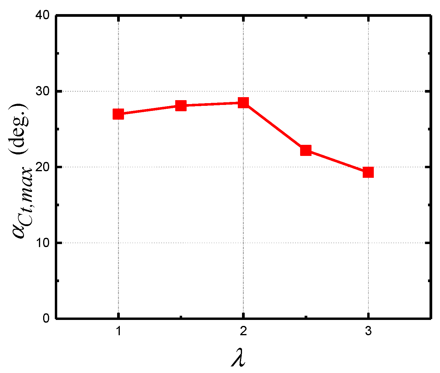
Figure 16 shows the azimuth of the maximum tangential force coefficient θct.max as a function of the tip speed ratio, and the horizontal axis is divided by five tip speed ratios. It can be seen from the figure that the θct.max increases first and at a level between 90° and 100° with the increase of λ. Figure 17 shows the angle of attack of the maximum tangential force coefficient αct.max as a function of the tip speed ratio. It was found that when λ ≤ 2, the αct.max is approximately above 26°, which is similar to the result observed in [15]. As can be seen from Figure 10, the relative angle of attack of the blade can be higher than 26° only when λ ≤ 2; when λ > 2, θct.max = θα, max, where θα, max represents the azimuth of the maximum angle of attack, which is also observed in Figure 17. In summary, it can be considered that when the blade moves to an angle of attack higher than 26°, or when moving to the maximum angle of attack (the maximum angle of attack αmax is less than 26°), the tangential force reaches a maximum value and the flow begins to stall. The specific reasons have been analyzed above, as shown in Figure 10 and Figure 15.
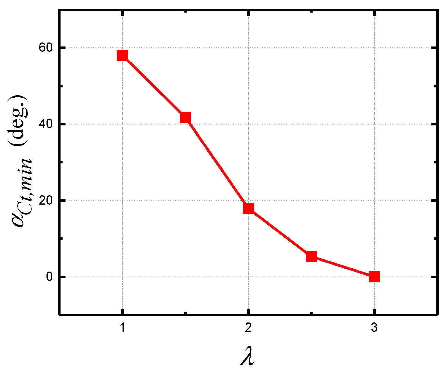
Figure 18 and Figure 19 show the change of the azimuth θct.mix and the angle of attack αct.mix with the tip speed ratio, respectively, where the minimum tangential force coefficient is located. It was found that θct.mix rised with the tip speed ratio, while αct.mix reduced with the tip speed ratio. The tangential force stall azimuth interval is defined as θct.stall,
θct.stall, = θct.mixθct.max.
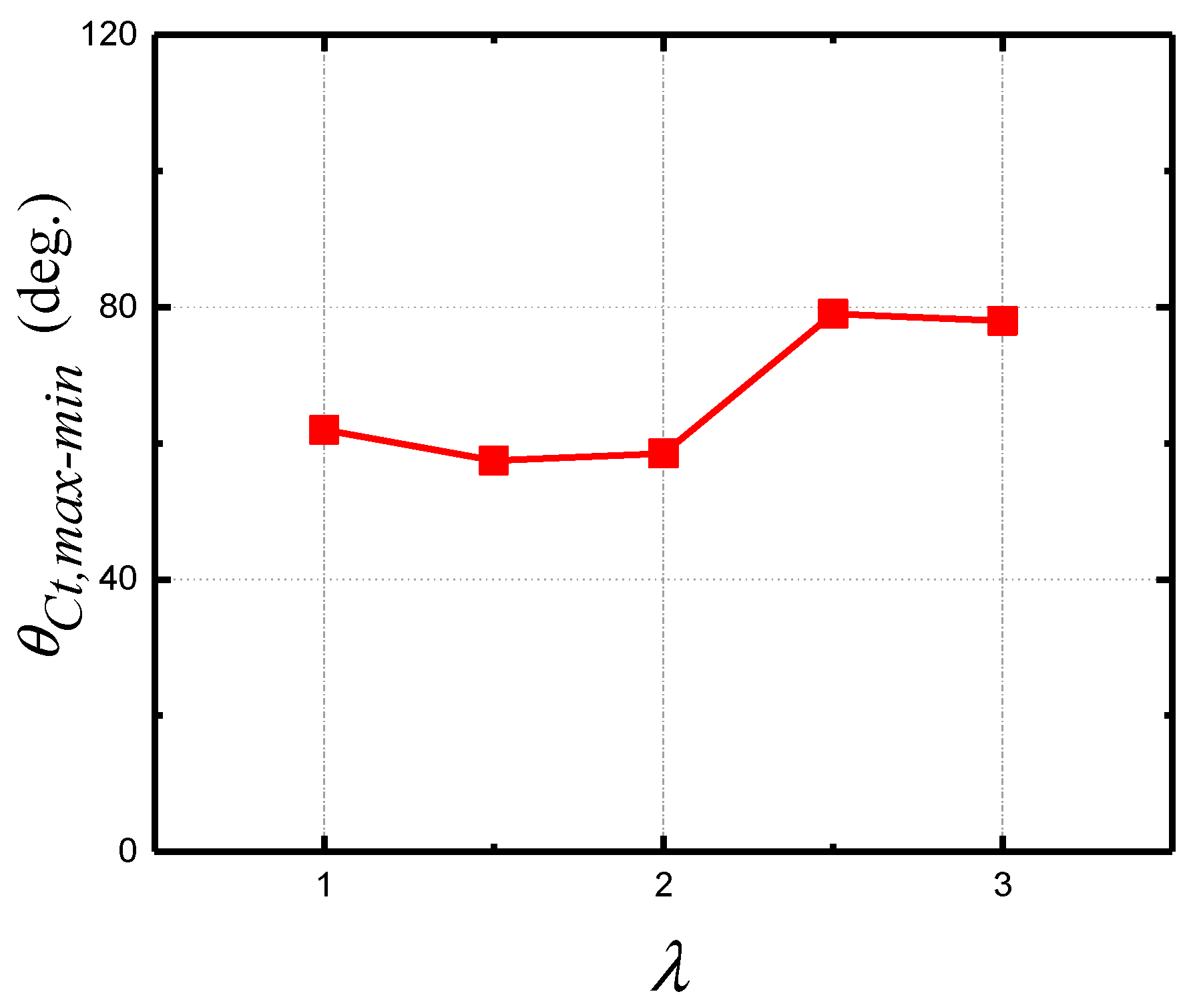
Figure 20 shows the variation of θct.stall, with the tip speed ratio.
It is found that the tangential force stall azimuth is about 60° ± 5° when the blade is moving at a low tip speed ratio (i.e., αmax > 26°); while the stall azimuth is about 80° ± 5° at high tip speed ratio.

3.3. Influence of Plasma Actuation Flow Control Strategy on VAWT

In this part, the wind turbine is selected to operate at a tip speed ratio of 2.15. Because according to Figure 11, when the tip speed ratio is 2.15, the wind turbine has a maximum power coefficient in the experiment.
The effect of the plasma actuator positions on VAWT was studied. The actuator is placed at 5% c, 30% c, 50% c, 70% c, and 90% c from the leading edge, respectively. Cp of the VAWT with different plasma actuation positions is shown in Table 2. The baseline case is uncontrolled VAWT rotate at a tip speed ratio of 2.15. In contrast, it has been found that using plasma actuator at these five positions can increase the Cp of the VAWT. The optimal position is at 30% c and the power is increased by 36%. Figure 21 shows the variation of the tangential force coefficient with azimuth at different plasma actuator positions. In general, the actuation increases the maximum tangential force of the blade. At 15° < θ < 165°, plasma actuation can significantly increase the tangential force. However, when θ > 165°, the actuation has less effect.
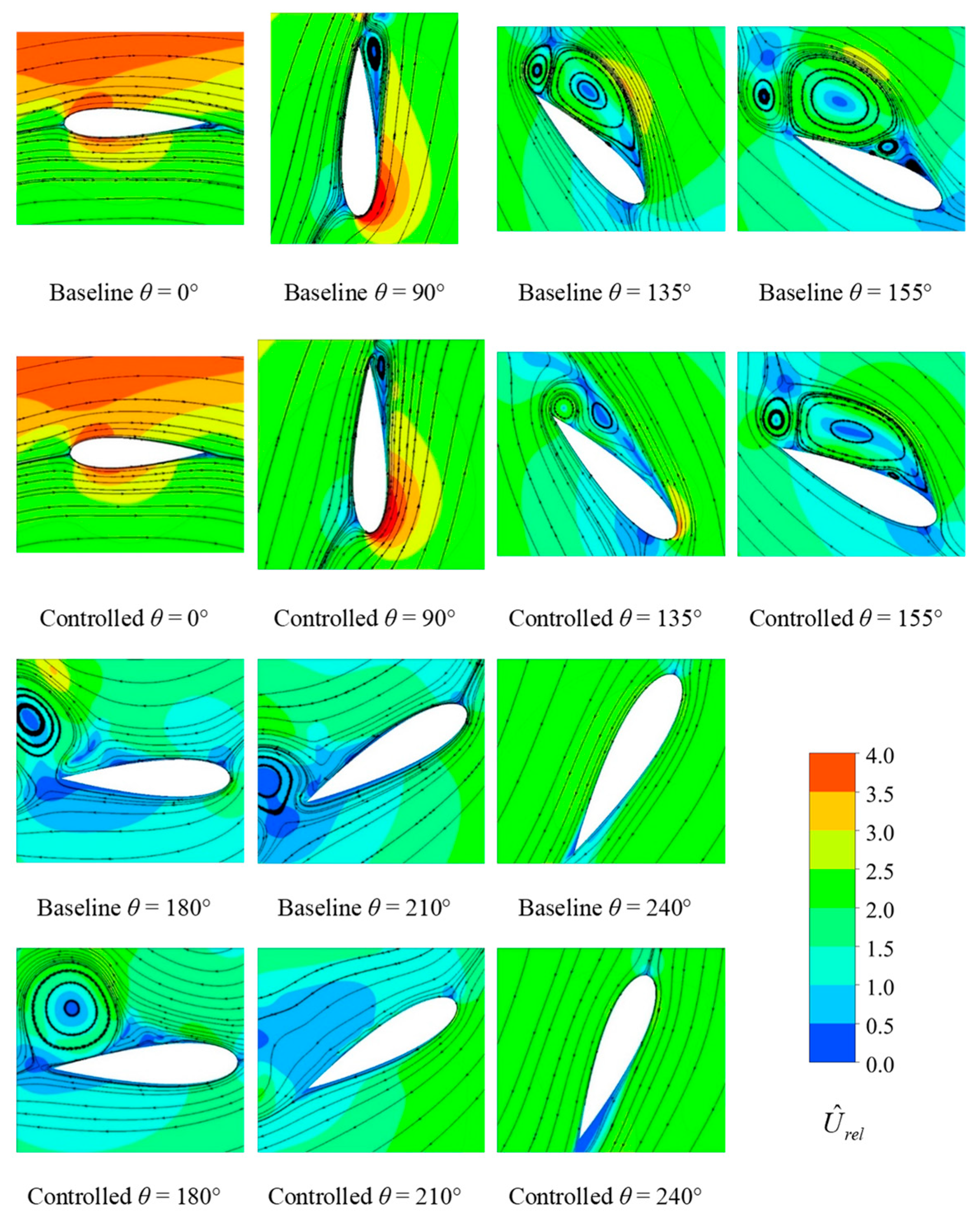
Figure 22 shows the relative velocity contour with relative velocity streamlines. The flow fields before and after the controlled (the plasma actuator is at 30% c) were compared. When the actuator is at 30% c, plasma actuation can suppress flow separation, but does not completely eliminate flow separation. The baseline case forms a secondary vortex at θ = 135°, while the controlled case is formed at θ = 155°. Therefore, arranging the plasma actuator at 30% c, plasma actuation will delay the formation of the secondary vortex. It can also be seen from the comparison that the plasma actuation can accelerate the detachment of the vortex on the blade.
Ten control strategies were studied. The research schemes are shown in Table 1 and Table 3. According to that mentioned above, when the tip speed ratio is 2.15, it can be predicted that the H-type VAWT tangential force starts to stall at θ = 95° ± 5°, and ends the stall at θ = 155° ± 5°. The plasma actuation control strategies are developed accordingly.
The specific control strategy is shown in Table 3. Case 1 is a baseline and no plasma actuation is applied. In Case 2, the plasma is continuously pulsed on each of the blades during the rotation cycle. In Cases 3–10, the plasma is pulsed in different azimuthal intervals.
Figure 23 shows the variation of the tangential force coefficient with azimuth at the plasma actuation. It can be confirmed from the Case 1 curve that the above prediction is accurate. In general, within 90 ° < θ < 180 °, the tangential force coefficient is significantly improved by plasma, and has little effect on other azimuths. Cases 3, 4, and 7–9 show that the end azimuth of the actuation has little impact on the tangential force. Case 4–7 are used to investigate the effect of the starting actuation azimuth on the tangential force. It is found that the early actuation increases the tangential force and the peak value is higher. Cases 9 and 10 are a set of controlled trials. In the case of the same actuation interval size, the influence of the starting and ending position on the tangential force is studied. There is no significant difference between Case 9 and 10, however, when θ > 150° the tangential force of Case 10 is lower than Case 9.
Aerodynamic figure of merit (AFM) [42] is introduced to determine whether the active flow control strategy is cost effective. AFM is defined as
AFM = P controlled P actuators P baseline
where Pcontrolled is the power of controlled VAWT, Pactuators is the plasma actuators consumption, and Pbaseline is the power of uncontrolled VAWT. When AFM > 1, the power consumption of actuators is less than the additional output of VAWT, and the control strategy is feasible.
Table 4 shows the Cp and AFM for different control strategies. The power of VAWT can be directly calculated from the above, and the energy consumption of the plasma exciter is 6.67 W/m [16,17,43]. It can be seen that Case 2 increases the Cp up to 36%, but it is not suitable. Cases 6–10 are feasible, and the maximum Cp can be increased by 34.3%, in which Case 9 is optimal. Considering the consumption of the plasma actuator, Case 9 has the highest AFM value, which means that Case 9 consumes less energy and produces considerable power. Within the scope of the study, it is necessary to apply control in advance to achieve better control results.

4. Conclusions

In this paper, the phenomenological model and URANS simulation are used to study the VAWT dynamic stall phenomenon with different tip speed ratios. The effects of plasma actuation on the aerodynamic performance of the blade are explored, and the following conclusions are drawn:
  • As the dynamic stall of the vertical-axis wind turbine occurs, the boundary layer separation moves from the trailing edge to the leading edge. The boundary layer will reattach to the blade surface with the leading edge vortex and the secondary vortex shedding. With the increase of the tip speed ratio, the delay effect of the dynamic stall is more obvious.
  • The tip speed ratio affects the maximum and minimum values of the tangential force for a blade. When the tip speed is low, the maximum tangential force is at the azimuth of the α = 26°, and the minimum value is at the following 60° ± 5° azimuth. When the tip speed is high, the maximum tangential force is at the azimuth where the maximum angle of attack is, and the minimum is at the following 80° ± 5° azimuth.
  • The pulsed plasma actuation can effectively enhance the power of the vertical-axis wind turbine, and the actuation at 60° to 120° azimuth is optimal.

Author Contributions

Conceptualization, L.M.; Data curation, L.M.; Formal analysis, L.M.; Funding acquisition, X.W.; Investigation, L.M.; Project administration, X.W.; Supervision, J.Z.; Validation, J.Z. and S.K.; Writing—original draft, L.M.; Writing—review & editing, L.M.

Funding

This work was supported by National Natural Science Foundation of China (no. 51576065, 51876063).

Conflicts of Interest

The authors declare no conflicts of interest.

References

  1. Kantrowitz, A.R. A survey of physical phenomena occurring in flight at extreme speeds. In Proceedings of the Conference on High-Speed Aeronautics, New York, NY, USA, 20–22 January 1955; Volume 1955, pp. 335–339. [Google Scholar]
  2. Roth, J.R.; Sherman, D.M.; Wilkinson, S.P. Boundary Layer Flow Control with a One Atmosphere Uniform Glow Discharge Surface Plasma; American Institute of Aeronautics and Astronautics: Reston, VA, USA, 1998. [Google Scholar]
  3. Post, M.L.; Corke, T. Separation control using plasma actuators: Dynamic stall vortex control on oscillating airfoil. AIAA J. 2006, 44, 3125–3135. [Google Scholar] [CrossRef]
  4. Liu, Y.; Kolbakir, C.; Hu, H.; Meng, X.; Hu, H. An experimental study on the thermal effects of duty-cycled plasma actuation pertinent to aircraft icing mitigation. Int. J. Heat Mass Transf. 2019, 136, 864–876. [Google Scholar] [CrossRef]
  5. McCroskey, W. The Phenomenon of Dynamic Stall; NASA TM-81264; National Aeronuatics and Space Administration Moffett Field Ca Ames Research Center: Mountain View, CA, USA, 1981.
  6. Araya, D.B.; Dabiri, J.O. Vertical axis wind turbine in a falling soap film. Phys. Fluids 2015, 27, 091108. [Google Scholar] [CrossRef] [Green Version]
  7. Liu, Q.; Miao, W.; Li, C. Effects of trailing-edge movable flap on aerodynamic performance and noise characteristics of VAWT. Energy 2019, 192, 58–79. [Google Scholar]
  8. Liu, Q.; Hao, W.; Li, C.; Miao, W.; Ding, Q. Numerical Simulation on the Forced Oscillation of Rigid Riser with Helical Strakes in Different Section Shapes. Ocean Eng. 2019, 191, 106439. [Google Scholar] [CrossRef]
  9. Zhu, H.; Hao, W.; Li, C. Numerical investigation on the effects of different wind directions, solidity, airfoils and building configurations on the aerodynamic performance of building augmented vertical axis wind turbines. Int. J. Green Energy 2019, 16, 1216–1230. [Google Scholar]
  10. Miao, W.; Li, C.; Wang, Y.; Xiang, B.; Liu, Q.; Deng, Y. Study of Adaptive Blades in Extreme Environment using Fluid-Structure Interaction Method. J. Fluids Struct. 2019, 91, 102734. [Google Scholar] [CrossRef]
  11. Zhu, C.; Wang, T. Comparative Study of Dynamic Stall under Pitch Oscillation and Oscillating Freestream on Wind Turbine Airfoil and Blade. Appl. Sci. 2018, 8, 1242. [Google Scholar] [CrossRef]
  12. Yanzhao, Y.; Guo, Z.; Zhang, Y.; Jinyama, H.; Li, Q. Numerical Investigation of the Tip Vortex of a Straight-Bladed Vertical Axis Wind Turbine with Double-Blades. Energies 2017, 10, 1721. [Google Scholar] [Green Version]
  13. Qian, C.; Liu, X.; Ji, H.S.; Kim, K.C.; Yang, B. Aerodynamic Analysis of a Helical Vertical Axis Wind Turbine. Energies 2017, 10, 575. [Google Scholar] [Green Version]
  14. Sato, S.; Yokoyama, H.; Iida, A. Control of Flow around an Oscillating Plate for Lift Enhancement by Plasma Actuators. Appl. Sci. 2019, 9, 776. [Google Scholar] [CrossRef]
  15. Phan, M.K.; Shin, J. Numerical investigation of aerodynamic flow actuation produced by surface plasma actuator on 2D oscillating airfoil. Chin. J. Aeronaut. 2016, 29, 882–892. [Google Scholar] [CrossRef] [Green Version]
  16. Greenblatt, D.; Lautman, R. Inboard/outboard plasma actuation on a vertical-axis wind turbine. Renew. Energy 2015, 83, 1147–1156. [Google Scholar] [CrossRef]
  17. Benharav, A.; Greenblatt, D. Plasma-based feed-forward dynamic stall control on a vertical axis wind turbine. Wind Energy 2016, 19, 3–16. [Google Scholar] [CrossRef]
  18. Fujisawa, N.; Shibuya, S. Observations of dynamic stall on Darrieus wind turbine blades. J. Wind Eng. Ind. Aerodyn. 2001, 89, 201–214. [Google Scholar] [CrossRef]
  19. Wang, X.D.; Ye, Z.; Kang, S.; Hu, H. Investigations on unsteady aerodynamic characteristics of a horizontal-axis wind turbine during dynamic yaw process. Energies 2019, 12, 3124. [Google Scholar] [CrossRef]
  20. Buchner, A.J.; Soria, J.; Honnery, D.; Smits, A.J. Dynamic stall in vertical axis wind turbines: Scaling and topological considerations. J. Fluid Mech. 2018, 841, 746–766. [Google Scholar] [CrossRef]
  21. Christian, M.; Christophe, L.; Ion, P. Appropriate Dynamic-Stall Models for Performance Predictions of VAWTs with NLF Blades. Int. J. Rotating Mach. 1998, 4, 129–139. [Google Scholar]
  22. Zuo, W.; Wang, X.; Kang, S. Numerical simulations on the wake effect of H-type vertical axis wind turbines. Energy 2016, 106, 691–700. [Google Scholar] [CrossRef]
  23. Buchner, A.J.; Soria, J.; Honnery, D.; Smits, A.J. Dynamic stall in vertical axis wind turbines: Comparing experiments and computations. J. Wind Eng. Ind. Aerodyn. 2015, 146, 163–171. [Google Scholar] [CrossRef]
  24. Shyy, W.; Jayaraman, B.; Andersson, A. Modeling of glow discharge-induced fluid dynamics. J. Appl. Phys. 2002, 92, 6434–6443. [Google Scholar] [CrossRef]
  25. Massines, F.; Rabehi, A.; Decomps, P.; Ben Gadri, R.; Ségur, P.; Mayoux, C. Experimental and theoretical study of a glow discharge at atmospheric pressure controlled by dielectric barrier. J. Appl. Phys. 1998, 83, 2950–2957. [Google Scholar] [CrossRef]
  26. Suzen, Y.B.; Huang, G.; Jacob, J.; Ashpis, D. Numerical simulations of plasma based flow control applications. AIAA Pap. 2005, 4633, 2005. [Google Scholar]
  27. Abdollahzadeh, M.; Páscoa, J.; Oliveira, P.J.; Abdollahzadehsangroudi, M.; Páscoa, J. Modified split-potential model for modeling the effect of DBD plasma actuators in high altitude flow control. Curr. Appl. Phys. 2014, 14, 1160–1170. [Google Scholar] [CrossRef]
  28. Abdollahzadeh, M.; Pascoa, J.; Oliveira, P.J.; Abdollahzadehsangroudi, M.; Páscoa, J. Implementation of the classical plasma-fluid model for simulation of dielectric barrier discharge (DBD) actuators in OpenFOAM. Comput. Fluids 2016, 128, 77–90. [Google Scholar] [CrossRef]
  29. Abdollahzadeh, M.; Pascoa, J.C.; Oliveira, P.J. Comparison of DBD plasma actuators flow control authority in different modes of actuation. Aerosp. Sci. Technol. 2018, 78, 183–196. [Google Scholar] [CrossRef]
  30. Ma, L.; Wang, X.; Zhu, J.; Kang, S. Effect of DBD plasma actuation characteristics on turbulent separation over a hump model. Plasma Sci. Technol. 2018, 20, 139–149. [Google Scholar] [CrossRef]
  31. Ebrahimi, A.; Hajipour, M. Flow separation control over an airfoil using dual actuation of DBD plasma actuators. Aerosp. Sci. Technol. 2018, 79, 658–668. [Google Scholar] [CrossRef]
  32. Howell, R.; Qin, N.; Edwards, J.; Durrani, N. Wind tunnel and numerical study of a small vertical axis wind turbine. Renew. Energy 2010, 35, 412–422. [Google Scholar] [CrossRef] [Green Version]
  33. Maden, I.; Maduta, R.; Kriegseis, J.; Jakirlić, S.; Schwarz, C.; Grundmann, S.; Tropea, C. Experimental and computational study of the flow induced by a plasma actuator. Int. J. Heat Fluid Flow 2013, 41, 80–89. [Google Scholar] [CrossRef]
  34. Jayaraman, B.; Thakur, S.; Shyy, W. Modeling of fluid dynamics and heat transfer induced by dielectric barrier plasma actuator. J. Heat Transf.-Trans. ASME 2007, 129, 517–525. [Google Scholar] [CrossRef]
  35. Jayaraman, B.; Shyy, W. Modeling of dielectric barrier discharge-induced fluid dynamics and heat transfer. Prog. Aerosp. Sci. 2008, 44, 139–191. [Google Scholar] [CrossRef]
  36. Ostos, I.; Ruiz, I.; Gajic, M.; Gómez, W.; Bonilla, A.; Collazos, C. A modified novel blade configuration proposal for a more efficient VAWT using CFD tools. Energy Convers. Manag. 2019, 180, 733–746. [Google Scholar] [CrossRef]
  37. Bai, H.; Chan, C.; Zhu, X.; Li, K. A numerical study on the performance of a Savonius-type vertical-axis wind turbine in a confined long channel. Renew. Energy 2019, 139, 102–109. [Google Scholar] [CrossRef]
  38. Sagharichi, A.; Zamani, M.; Ghasemi, A. Effect of solidity on the performance of variable-pitch vertical axis wind turbine. Energy 2018, 161, 753–775. [Google Scholar] [CrossRef]
  39. Wong, K.H.; Chong, W.T.; Poh, S.C.; Shiah, Y.-C.; Sukiman, N.L.; Wang, C.-T. 3D CFD simulation and parametric study of a flat plate deflector for vertical axis wind turbine. Renew. Energy 2018, 129, 32–55. [Google Scholar] [CrossRef]
  40. Qin, N.; Howell, R.; Durrani, N.; Hamada, K.; Smith, T. Unsteady flow simulation and dynamic stall behaviour of vertical axis wind turbine blades. Wind Eng. 2011, 35, 511–527. [Google Scholar] [CrossRef]
  41. Danao, L.A.; Qin, N.; Howell, R. A numerical study of blade thickness and camber effects on vertical axis wind turbines. Proc. Inst. Mech. Eng. Part A 2012, 226, 867–881. [Google Scholar] [CrossRef]
  42. Stalnov, O.; Kribus, A.; Seifert, A. Evaluation of active flow control applied to wind turbine blade section. J. Renew. Sustain. Energy 2010, 2, 063101. [Google Scholar] [CrossRef]
  43. Corke, T.; Post, M.L.; Orlov, D.M. Single-dielectric barrier discharge plasma enhanced aerodynamics: Concepts, optimization, and applications. J. Propuls. Power 2008, 24, 935–945. [Google Scholar] [CrossRef]
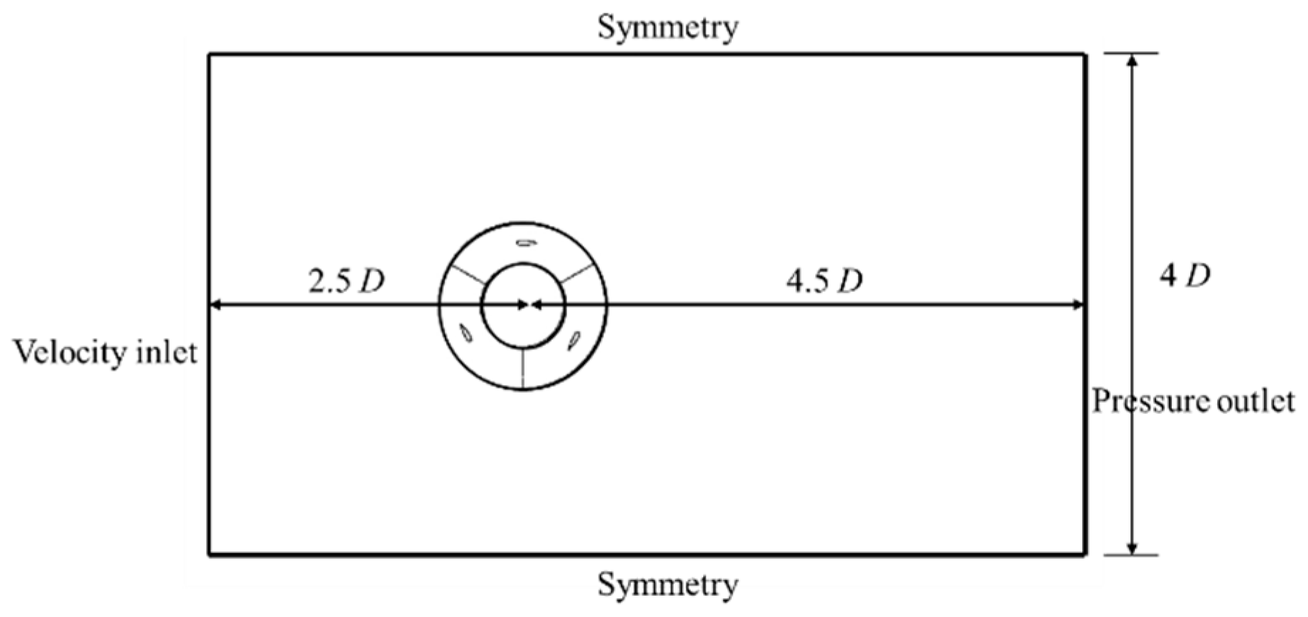
Figure 1. Computational domain and boundary conditions.
Energies 12 03738 g001
Figure 2. Position of each blade of VAWT.
Energies 12 03738 g002
Figure 3. Position of the plasma actuator on a blade.
Energies 12 03738 g003
Figure 4. Sketch of the plasma actuator.
Energies 12 03738 g004
Figure 5. Velocity distribution at different streamwise positions.
Energies 12 03738 g005
Figure 6. Global mesh of computational domain.
Energies 12 03738 g006
Figure 7. Mesh around the blade.
Energies 12 03738 g007
Figure 8. CFD validation: the tangential force coefficient with azimuth.
Energies 12 03738 g008
Figure 9. Convergence criterion: the tangential force coefficient with azimuth.
Energies 12 03738 g009
Figure 10. Angle of attack with azimuth.
Energies 12 03738 g010
Figure 11. Comparison of experimental data and numerical simulated data for wind turbine power coefficient.
Energies 12 03738 g011
Figure 12. Tangential force coefficient of a blade with azimuth.
Energies 12 03738 g012
Figure 13. Tangential force coefficient of a blade and vorticity contours with λ = 1.5.
Energies 12 03738 g013
Figure 14. Vorticity contours with different λ for selected azimuth.
Energies 12 03738 g014
Figure 15. Vorticity contours with different λ at θ = 120°.
Energies 12 03738 g015
Figure 16. θct.max of a blade with λ.
Energies 12 03738 g016
Figure 17. αct.max of a blade with λ.
Energies 12 03738 g017
Figure 18. θct.mix of a blade with λ.
Energies 12 03738 g018
Figure 19. αct.mix of a blade with λ.
Energies 12 03738 g019
Figure 20. θct.max-mix of a blade with λ.
Energies 12 03738 g020
Figure 21. Tangential force coefficient with azimuth at different plasma actuator positions.
Energies 12 03738 g021
Figure 22. Relative streamlines and relative velocity contours with azimuth for baseline and plasma controlled case (actuator at 30% c).
Energies 12 03738 g022
Figure 23. Tangential force coefficient of a blade with azimuth at plasma actuation.
Energies 12 03738 g023
Table 1. Parameters of the simulations.
Parameter SettingsλActuator PositionDtcf/HzActuation Interval
Scheme 11~3----
Scheme 22.155 different positions0.2383-
Scheme 32.150.3c0.238310 different actuation intervals
Table 2. Cp with different plasma actuator positions.
Position of the Plasma ActuatorCp
Baseline0.261
5% c0.324
30% c0.358
50% c0.355
70% c0.315
90% c0.262
Table 3. Strategies of plasma actuation control.
StrategyActuation Azimuth IntervalStrategyActuation Azimuth Interval
Case 1No controlCase 670° to 150°
Case 2Global controlCase 760° to 150°
Case 390° to 160°Case 860° to 130°
Case 490° to 150°Case 960° to 120°
Case 580° to 150°Case 1050° to 110°
Table 4. Cp and AFM at plasma actuation.
StrategyCpAFMStrategyCpAFM
Case 10.261-Case 60.3311.033
Case 20.3580.304Case 70.3431.048
Case 30.2960.928Case 80.3311.062
Case 40.2990.968Case 90.3261.072
Case 50.3100.982Case 100.3221.056