Article

Metal Hydride Beds-Phase Change Materials: Dual Mode Thermal Energy Storage for Medium-High Temperature Industrial Waste Heat Recovery

by
Serge Nyallang Nyamsi
1,
Ivan Tolj
2,* and
Mykhaylo Lototskyy
1
1
South African Institute for Advanced Materials Chemistry, University of the Western Cape, Private Bag X17, Bellville 7535, South Africa
2
Faculty of Electrical Engineering, Mechanical Engineering and Naval Architecture, University of Split, Rudjera Boskovica 32, Split 21000, Croatia
*
Author to whom correspondence should be addressed.
Energies 2019, 12(20), 3949; https://doi.org/10.3390/en12203949
Submission received: 1 October 2019 / Revised: 11 October 2019 / Accepted: 15 October 2019 / Published: 17 October 2019
(This article belongs to the Section D: Energy Storage and Application)

Abstract

:
Heat storage systems based on two-tank thermochemical heat storage are gaining momentum for their utilization in solar power plants or industrial waste heat recovery since they can efficiently store heat for future usage. However, their performance is generally limited by reactor configuration, design, and optimization on the one hand and most importantly on the selection of appropriate thermochemical materials. Metal hydrides, although at the early stage of research and development (in heat storage applications), can offer several advantages over other thermochemical materials (salt hydrates, metal hydroxides, oxide, and carbonates) such as high energy storage density and power density. This study presents a system that combines latent heat and thermochemical heat storage based on two-tank metal hydrides. The systems consist of two metal hydrides tanks coupled and equipped with a phase change material (PCM) jacket. During the heat charging process, the high-temperature metal hydride (HTMH) desorbs hydrogen, which is stored in the low-temperature metal hydride (LTMH). In the meantime, the heat generated from hydrogen absorption in the LTMH tank is stored as latent heat in a phase change material (PCM) jacket surrounding the LTMH tank, to be reused during the heat discharging. A 2D axis-symmetric mathematical model was developed to investigate the heat and mass transfer phenomena inside the beds and the PCM jacket. The effects of the thermo-physical properties of the PCM and the PCM jacket size on the performance indicators (energy density, power output, and energy recovery efficiency) of the heat storage system are analyzed and discussed. The results showed that the PCM melting point, the latent heat of fusion, the density and the thermal conductivity had significant impacts on these performance indicators.

1. Introduction

Waste heat is inherently the byproduct of any industrial process varying from thermal power plants, crude oil refineries, steel industries to transportation. For instance, in thermal power plants where coal or diesel is burned to produce power (electricity), more than 30% of its chemical energy is wasted (discharged) [1] to the environment. This ultimately leads to a generally 20–40% heat-to-work conversion efficiency. This heat discharging to the environment may lead to thermal pollution, which as a result, increases the ambient temperature in the long run. Figure 1 displays the life cycle of waste heat from the industrial process to end-users. Several solutions for waste heat recovery have been proposed and analyzed. The multi-generation processes, such as the combined heat and power (CHP) or combined cooling heating and power (CCHP), have been the predominant waste-heat recovery methods in power plants. These multi-generation processes allow for an improvement of thermal energy efficiency of up to 80%. On the other hand, for industrial process heat, the organic Rankine cycle (ORC), thermoelectric generators, heat pumps, and heat storage have been reviewed as potential methods for waste heat recovery [2]. However, the efficacy of either heat recovery method depends on the conditions at which heat is discharged (especially the temperature). There are mainly three factors affecting the implementation of waste heat recovery: the availability, the heat amount and quality (which is the temperature range). The temperature range depends on the waste heat source which ranges from thermal power plants (diesel engines, fossil fuels-fired power plants, PEM, and solid oxide fuel cells) to industrial processes (steel, cement, etc). On the one hand, if the heat is available at a constant temperature, therefore the selection of ORC and thermoelectric generators for heat recovery can improve the overall energy efficiency by generating extra electricity to the end-users. On the other hand, if the temperature of the waste heat fluctuates in a small or great range, domestic hot water or steam production using heat exchangers is the viable option [3,4,5,6,7]
Although ORCs are attractive for waste heat to work conversion applications, it is noticed that they possess low thermal efficiency of approximately 5–10% [8]. This energy efficiency is greatly improved to 15–30% by identifying and optimizing the parameters affecting their performance [9,10]. It was also shown that the insertion of a recuperator at the downstream of the expander could improve the efficiency to up 30% [11]. However, the improvement of thermal efficiency cannot outweigh the capital cost of the installed ORC components, which make the ORC very prohibitive in some practical cases. On the other side, thermoelectric generators are made of semiconductors that are very expensive to synthesize and characterize [4]. Moreover, energy efficiency is as low as 2%, which cannot justify their implementation in large-scale waste-heat recovery applications [6,7].
Thermal energy storage (TES) is another emerging method of waste heat recovery, which has attracted worldwide interest, since it may narrow the gap between heat availability and heat demand [12]. Unlike ORC and thermoelectric generators, which have to be implemented on-site where the waste heat is generated, thermal energy storage systems offer the advantage to be utilized on-site or off-site which make them fixed system or mobilized. TES can be classified into three types: Sensible heat storage, latent heat storage, and thermochemical heat storage. Among the three types, latent and thermochemical heat storages are the most appealing due to the high energy density that can be stored. There is a plethora of studies investigating the performance of thermochemical heat storage and latent heat storage for waste heat recovery.
To alleviate the intermittency of the industrial waste-heat source, a few authors suggested a combination of phase change material (PCM)-based TES with conventional waste-heat recovery components. For example, Magro et al. [13] analyzed the integration of a PCM-based technology in an existing ORC-based waste-heat recovery in steel billet reheating furnaces. The purpose of the PCM-based technology is to reduce the thermal power fluctuation of waste heat sources. The results showed that the integration of PCM slightly improved the ORC thermal efficiency from 15.5 to 16.4% while its capacity significantly increased from 38 to 52%. Following the same idea, Yu et al. [14] investigated the performance of a combined ORC with latent heat storage for engine waste-heat recovery. They established the melting/freezing model of different PCMs under dynamic heating. Among these PCMs, LiNO3-KCl-NaNO3 was identified as optimal heat storage media for engine exhaust heat recovery. By integrating these PCMs to ORC under dynamic heat source simulation, the results showed that continuous power output could be provided regardless of the fluctuation of engine exhaust heat. Moreover, by doubling the amount of latent heat storage systems, the total power output could be increased by 17.2%. Pandiyarajan et al. [15] experimentally investigated the integration of a combined heat exchanger and TES system. The results showed that 10 to 15% of fuel chemical energy could be stored as heat in the TES system, which was available at a reasonably higher temperature for suitable applications. They further evaluated and reported the performance parameters characterizing the combined heat exchanger-heat storage tank. Ortega-Fernández and Rodriguez-Asequinolaza [16] investigated the integration of thermal energy storage systems-based waste heat recovery to the steel making plant. They studied the possibility of using steel slag as potential heat storage material. The analysis of a TES based on dual media packed bed showed that a large pressure drop is induced inside the beds, which makes it a critical design parameter (as large pressure drops were induced during dynamic operation of the system). The results also showed that after optimization, the energy efficiency ranging from 65 to 85% could be achieved when integrating the TES system. Gopal et al. [17] conducted a thermodynamic analysis of a diesel engine integrated with PCM-based TES. To this end, the energy and exergy diagrams were drawn. The results showed that by using TES systems, more than 6.13% of the fuel chemical energy could be saved. Additionally, the energy and exergy efficiencies of the integrated system were varied in the range 3.1–34.15%and 0.25–27.41%, respectively. Wang et al. [18] proposed a mobilized thermal energy storage system (M-TES) to recover waste-heat from the industrial site and deliver heat off-site to the end users (Since industrial areas are located at long distances from the residential area). To understand the mechanisms of the heat charging/discharging process, a lab-scale prototype was designed and developed. Erythritol-PCM was chosen as the working material due to its high latent heat (330 kJ∙kg−1) and melting point, 118 °C. Guo et al. [19] conducted a techno-economic assessment of M-TES for distributed users. The cost and income of M-TES were estimated based on the net present value and payback period methods. The results showed that the cost using M-TES to supply heat is primarily determined by: The distance between the heat availability (industrial site) and the heat demand (end-users); the quantity (energy density); and the quality (temperature) of heat demand. By performing a sensitivity analysis, it was shown that the cost of M-TES was more sensitive to the price of PCM than the other parameters [20]. From a performance point of view, the rate at which energy is stored or restored is the main limitation to the implementation of these technologies. This is due to the low thermal conductivity of phase change materials (PCM) in the liquid/solid phase which sometimes is in the range 0.1–0.24 W∙m−1∙K−1 [21]. Therefore, some effective and passive heat managements have been proposed. They consist of the insertion of high thermal conductivity materials such as graphite, metal foams or high surface area fins [22,23,24,25]. For example, Py et al. [24] showed that the thermal conductivity of the PCM could increase from 5–70 W∙m−1∙K−1 when using a composite PCM/graphite matrix. On the other hand, Yang et al. [25] showed that the insertion of annular fins inside a cylindrical reactor containing a PCM could lead to a 65% reduction of the full melting time.
Despite all these efforts, solid-liquid PCMs used in waste-heat recovery applications are limited in energy storage density and operation temperature (<250 °C). In order to improve the recovered energy density, some authors proposed the utilization of heat pipes technology. The heat pipe is a passive heat management that has gained popularity in electronic industries. It generally contains liquid-vapor PCM, which compared to its counterpart solid-liquid PCM, possesses high-energy storage capacity (heat of vaporization > heat of fusion). Jouhara et al. [26] designed and tested a flat heat pipe heat exchanger in a lab and at an industrial scale. The results indicated that in industrial tests, the heat recovery of 10 kW could be possible. Moreover, this heat capacity could be scalable to ¾ MW when the heat pipe was increased to 70 m long. Ma et al. [27] designed a heat pipe heat exchanger to recover heat from the slag cooling processes in steel industries. Its performance was assessed from the first and second law of thermodynamics. The results revealed that the heat exchanger effectiveness decreased from 0.19 to 0.09, while the exergy efficiency increased from 34 to 41% when wastewater flow-rate varied from 0.83 to 1.87 m3/h. By optimizing the design, an amelioration of 7.19 and 7.93% was seen in the heat exchanger effectiveness and the exergy efficiency, respectively.
This small literature survey clearly emphasized the great interest given to PCM-based TES for industrial waste-heat recovery. However, there is a scarce utilization of thermochemical based TES for industrial waste-heat recovery applications. The selection of thermochemical materials for energy storage is further motivated by the fact they can store energy with a density of 2–10 folds higher than that of PCM [21]. Furthermore, thermochemical energy materials allow for long-term energy storages as compared to PCMs, which are prone to thermal losses when stored for a long period. To date, metal hydrides, salts (e.g., metal halides) hydrates and ammoniates are the most utilized thermochemical materials for closed sorption systems driven by waste-heat intended for refrigeration [28,29,30,31,32,33,34], heat pumps and transformer applications [34,35,36,37]. The well-accepted layout of these sorption systems is two tanks interconnected, filled with a high temperature (HT) sorbent in one side, and a low temperature (LT) sorbent in the other side. The HT sorbent is used to store and recover useful heat, while the LT material is used to store the sorbate or produce cold energy [28].
Li et al. [28] reported the development of a sorption thermal battery for low-grade waste heat recovery and combined cold and heat energy storage. Two sorption batteries based on MgCl2-NH3 and NaBr-NH3 working pairs were analyzed and experimentally tested. The results showed that cold and heat energy densities were 0.6 MJ∙kg−1 and 1.498 MJ∙kg−1, respectively. Verde et al. [29] investigated the performance of a prototype of waste-heat driven adsorption system for automotive air conditioning. The adsorption system was made of a two-tank silica gel adsorption chiller. A dynamic model taking into account the mass transfer resistance and pressure drop for each component of the system was formulated. The results showed that the model was able to predict with good accuracy the dynamic performance under different operating conditions and configuration modes. The chiller could produce 2.1 kW with a COP of 0.35 at the rated conditions. Furthermore, the integration of the heat recovery system improved the COP by 43% and cooling power by 4%. Gao et al. [30] experimentally investigated a two-stage solid sorption freezing system based on the adsorbents pair (two-bed) MnCl2-CaCl2-NH3. The experimental results showed that a maximum refrigerating capacity of 1.25 kW and a coefficient of performance (COP) of 0.143 were obtained in 2 h resorption process at the waste heat and refrigerating temperatures of 230 °C and −5 °C, respectively. It was also shown that the refrigerating capacity could increase to 1.32 kW when the waste heat and refrigerating temperatures were changed to 270 and −10 °C, respectively. Lu et al. [31] experimentally demonstrated the feasibility of an adsorption air conditioner driven by exhaust heat from diesel locomotives. The adsorption bed utilizes a zeolite-water working pair to provide chilled water. The results showed that the refrigerating power varied in the range of 3–4.2 kW with an average COP of 0.21. In addition, it was revealed that the exhaust heat temperature was affected by the running speed of the locomotive, which in turn affected the refrigerating power and COP. Jiang et al. [32] experimentally investigated the performance of a TES based on the adsorption working pair MnCl2-CaCl2 in a weight ratio 4.8/3.9 kg. The results showed that the maximum energy storage density of 1.836 MJ∙kg−1 could be attained when the system was heat charged and discharged at 155 and 55 °C, respectively. On the other hand, the volumetric energy density varied from 144–304 kWh∙m−3. Furthermore, it was shown that the energy efficiency decreased from 97 to 73% as the discharging temperature increased from 55 to 75 °C. Jiang et al. [33] analyzed the performance of an innovative modular sorption and resorption thermal cell for cold and heat cogeneration. To improve the heat and mass transfer, the adsorbents composite pair were a mixture of metal halides with expanded natural graphite (ENG), treated with sulfuric acid. The results showed that the sorption capacity of the different pairs ranged from 16.9 to 49.9 wt.%. Furthermore, the heat storage density was in the range of 0.580–1.368 MJ∙kg−1, while the cold energy density varied in the range of 0.4–1.134 MJ∙kg−1. Interestingly, both the heat and cold power density were relatively high (0.222–1.502 kW∙kg−1). Qin et al. [34] proposed and developed a new metal hydride refrigeration system for vehicle air conditioning driven by waste heat coming from the vehicle’s exhaust gas. The system utilized AB5-type hydrides pair with appropriate thermal properties. The results showed that the fluctuated refrigeration cycles were obtained with an average cooling power of 84 W and COP of 0.26 (lower than the theoretical COP of 0.711). It was concluded that the COP of such sorption thermal energy storage systems deteriorates because of the limitations of heat transfer enhancement [35]. Isselhorst and Groll [37] experimentally used a working pair of AB5-type hydride materials to upgrade the waste-heat temperature of ca. 130–140 °C to temperatures higher than 200 °C. A power density of 38 W/kg-alloy was obtained at a COP = 0.27.
A full comparison of different thermochemical energy storage materials such as salt hydrates, salt ammoniates and metal hydrides, is not straightforward, since all their thermo-physical and thermodynamics properties are not readily available in the literature. However, based on the heat of reaction (which is intimately linked to the gravimetric energy storage), metal hydrides have higher energy density compared to metal halides (salt)-hydrates or ammoniates. This holds true for the same metal under consideration. For instance, based on the data provided in [28], the energy density of the working pair MgCl2-NH3 is 2.29 MJ∙kg−1, which is less than that of Mg-H2 (2.9 MJ∙kg−1) [38]. Similarly, the salt hydrate, MgCl2·6H2O has an energy density as low as 0.2 MJ/kg. Besides, from an operation temperature viewpoint, metal hydrides have great range of operation (from −50 to 1000 °C) relative to that of salt hydrates and ammoniates (−40 to 300 °C). For this reason, metal hydrides have also been applied successfully to medium-high temperature TES [38,39,40,41]. Bogdanovic et al. [38] experimentally investigated the operation performance of a process steam generator integrated with a MgH2/Mg heat storage unit. The overall system could provide 9.08 kWh of heating output at 370 °C with an energy efficiency of 79.6% Reiser et al. [39] experimentally investigated the physical and thermodynamic properties (energy density, thermodynamic properties, operating temperature range, cyclic stability) of Mg/MgH2, Mg-Ni/Mg2NiH4 systems for energy storage applications. The results showed that these materials were stable in the temperature range of 250–550 °C with thermal energy densities reaching up to 2.257 MJ∙kg−1. A methodology of selecting metal hydrides pairs for solar heat storage applications based on two important criteria, such as energy storage density and efficiency, was proposed by [40]. It was found that the pairing of Mg-based hydride with well-known low-temperature metal hydrides LaNi5 could achieve an energy efficiency of 70–80% with energy storage density close to 1 GJ∙m−3. Moreover, during the discharge process, the temperature of the heat transfer fluid could be increased by 25 °C, which is beneficial for the exergetic efficiency of a power plant located downstream of the TES system. Using a techno-economic analysis, Corgnale et al. [41] reported promising metal hydrides for TES-based concentrated solar plants (CSP). In such applications, high-temperature metal hydrides (HTMH) such as alkali metal hydride (LiH, NaH), alkali-earth metal hydrides (MgH2, CaH2) and TiH2, operate at very high temperature ranging from 500 to 1050 °C, which is suitable from an exergetic point of view. It was reported that the exergy efficiency of these hydride materials was in the range 71–95 % with TiH2 depicting the highest efficiency of 95%. Moreover, the superior energy density ca. 500–1700 kWhth∙m−3 for these materials was found. Unfortunately, the installed cost of TES was still high varying in the range 9–26$/kWhth, where the cost of the raw materials took the big share (80–85%).
It is obvious from previous research that closed sorption heat pumps or TES systems using two-beds suffer from low energy efficiency or COP, which is the ratio between the useful cooling/heating energy and the energy input. One simple solution to improve the energy efficiency is to integrate an internal heat recovery device. For this purpose, only a small amount of studies addressed the problem. An analysis of metal hydride heat pump integrated with a heat exchanger for internal heat recovery was conducted by Yang et al. [42]. The results showed that the COP could increase up to 1.4 when 100% internal heat recovery was assumed. In order to reduce the energy requirements during the hydrogenation/de-hydrogenation cycle of metal hydride tanks, several authors [43,44] suggested the integration of PCM as a passive heat transfer management. The objective of this study is to propose a combined two-tank latent and thermochemical heat storage for waste heat recovery. For this purpose, the metal hydride pair Mg2NiH4/LaNi5 is chosen. Besides, a low temperature PCM is introduced to store/restore the reaction enthalpy of LaNi5 during the heat charging/discharging cycle. The work is presented as follows. In the first section, the description of the new design of two-tank TES is presented. The justification of the integration of a latent heat storage system is given based on the overall energy efficiency. Then, a 2D mathematical model is formulated to study its performance under transient conditions. The results provide some insights into the role of PCM as an internal heat recovery media and into the performance of two-tank thermochemical heat storage for industrial waste heat recovery.

2. Problem Description

The conventional two-tank TES has been proposed for concentrated solar power plants and other related heat-driven processes such as heat pumps [28,40,41]. It consists of a pair of thermochemical materials beds filled on the one side with a high-temperature material and the other side with a low-temperature material. Figure 2a displays the operation principle of a conventional two-packed-bed TES using metal hydrides. The HTMH bed is used to store heat due to its high temperature operating condition and high energy density, while low-temperature metal hydride (LTMH) is used for hydrogen storage. During the heat charging process, the HTMH (M1H) absorbs heat and the metal hydride M1H desorbs hydrogen (because of endothermic reaction). This hydrogen flows through the valve and it is absorbed by the metal M2. This reaction generates heat Q2 which is dumped to the environment. When heat is needed (heat discharging process), Q2 is provided to the LTMH bed and as a result, M2H dissociates in M2 and the hydrogen flows back to the HTMH bed. The reaction between M1 and hydrogen generates high-temperature heat, which can be used for different heat duties (steam turbine to produce electricity). In this case, the overall efficiency which is the ratio between the heat output to the heat input is given by this relation (Equation (1)). Note that the LTMH is ideally selected in such a way that its heat of reaction Q2 is 2–4 fold lower than the heat of reaction of HTMH (Q1)
η = Q 1 γ Q 1 + Q 2 + γ
where, γ and γ account for thermal masses in the storage system.
In order to improve the efficiency, a passive thermal management technique was proposed. Here, the LTMH bed is enclosed in a PCM jacket as can be seen in Figure 2b. In such a case, during the heat charging the heat desorbed from the LTMH bed is stored in the PCM. As a result, the PCM liquefies. During the heat discharging, the PCM gives up the heat to LTMH by solidifying and hydrogen flows from LTMH to HTMH to produce the useful heat Q1. By integrating the PCM, the hypothetical energy efficiency reads as follows:
η = Q 1 γ Q 1 + γ
Many factors, such as the PCM properties, can greatly affect this energy efficiency. Therefore, the selection of the PCM is of paramount importance, especially the melting temperature. In order to give further insights on how the performance of the system is affected, an examination of the Van’t Hoff diagram depicted in Figure 3 can be undertaken. During the heat charging process (path 1-2), Q1 is provided at Th and hydrogen flows from HTMH to the LTMH bed. Meanwhile, heat is removed from LTMH bed at T1 and stored in the PCM. However, since the equilibrium pressure in state 3 is less than that in state 1, the heat discharging process cannot occur. To trigger the heat discharging process, the equilibrium pressure of state 1 has to be lowered. This is done by removing sensible heat from the HTMH bed to Th1 (cooling process to 4). As soon as the equilibrium pressure of 3 is higher than that of 4, then H2 flows from LTMH to the HTMH bed and heat is given at Q1o. Note that due to thermal masses, Q2i < Q2 and Q1o < Q1, affect the final energy efficiency of the storage system. Finally, from these above-described working principles, there are two critical parameters which can be seen, Th1 and Tm (melting temperature of the PCM) that can be adjusted in order to optimize the energy storage system.

3. Mathematical Model

A 2D computational model for simplification was formulated and investigated. The 2-D axis-symmetric model is depicted in Figure 4, which consists of a tubular reactor in which the inner tube of radius r0 serves as a hydrogen channel. Each metal hydride bed has a thickness (rMHr0 = 15 mm). The heat transfer between the HTMH and the heat transfer fluid (HTF) is made possible through the reactor wall of a constant thickness (δ = 2 mm). The length of each bed is fixed at LMH1 = LMH1 = 450 mm. The jacket of LTMH (LMH1 = 470 mm and radius rPCM = 40 mm) is filled with a phase change material, fully insulated from the outside [44,45].

3.1. Governing Equations

3.1.1. Metal Hydride Reactors

The following hypotheses are made for metal hydride reactors [40,46]:
  • The thermo-physical properties of hydrides are temperature and concentration-independent.
  • The thermal equilibrium between the gas and solid is established.
  • The thermal loss due to the radiative heat transfer is neglected for the case of Mg hydride materials
  • The hydrogen gas pressure inside the reaction bed is constant.
  • The equilibrium pressure in the absorption and desorption processes is unchanged i.e., the hysteresis is negligible.
Energy balance
Due to the thermal equilibrium, only one heat balance equation is used in order to compute the bed temperature as follows:
( ρ C p ) e f f T t + · ( ρ g C p g V T ) = λ e f f 2 T + ( 1 ε ) M g ρ M H w t d α d t Δ H
where the equivalent heat capacity and the thermal conductivity are assessed, using the volume average:
( ρ C p ) e f f = ε ρ g C p g + ( 1 ε ) ρ M H C p M H
λ e f f = ε λ g + ( 1 ε ) λ M H
The energy balance of the reactor wall is expressed as follows:
( ρ C p ) w a l l T w a l l t = λ w a l l 2 T w a l l
Mass balance
ε ρ g t + · ( ρ g V ) = ( 1 ε ) ρ M H w t d α d t
where the velocity of hydrogen gas in the porous bed is governed the Darcy’s law.
V = K e f f μ g p
However, the Navier-Stokes momentum equation describes the hydrogen velocity in the connecting pipe, as follows:
t · ( ρ g V ) + · ( ρ g V · V ) = p + μ g 2 V
The reaction kinetics of metal hydrides takes the following the general differential form:
d α d t = k a , d e x p ( E a , d R T ) f a , d ( p ) g a , d ( α )
The function f includes the effect of H2 pressure on the kinetic rate, it reads as Equation (11), where the top one is used for H2 absorption and the bottom one for H2 desorption
f a , d ( p ) = {   l n ( p p e q ) ( p p e q p e q )
The Van’t hoff equation is used to express the equilibrium pressure where the plateau slope is neglected:
ln ( p e q p 0 ) = Δ H R T Δ S R
The ab/desorption rate is described by the first order reaction for low (LaNi5) and high (Mg2Ni) temperature hydrides such as [27,38]
g a , d ( α ) = { 1 α α

3.1.2. Phase Change Materials

The selection of any phase change material (PCM) for practical applications is governed by several important criteria: melting/solidification temperature; latent and sensible heat capacities; thermochemical stability; cyclic behavior; heat and transfer properties (thermal diffusivity, viscosity); cost; corrosiveness; and flammability (low vapor pressure). Among different PCM, paraffin waxes are the most popular and commercially available for low-temperature applications [21].
By definition, PCMs are materials that absorb/release heat at a constant temperature while changing their phase from solid-liquid or vice versa. However, practically it is not the case. From experiments, it is seen that the transition phase (also called mushy zone) occurs on relatively small to high-temperature intervals. In order to accurately model the thermal behavior of PCM, the experimental profile (Figure 5 adapted from [47,48]) of the heat capacity generally determined by differential scanning calorimetry (DSC) is examined. For example, the DSC of paraffin RT35 (Rubitherm Technologies GmbH, Germany) is plotted in Figure 1 in [35,36]. Several features of PCM transpire from these graphs: The heat capacity profile depends on the heating rate used in the experiments. The melting point or temperature is almost located at the peak of the melting profile. Note that the characterization of PCM is not very consistent through the literature. While some authors assumed that the melting temperature Tm is the onset temperature Ton during melting (beginning of the peak) [19], others assumed that Tm is the peak temperature of the heat capacity profile [47,48]. As a result, at Tm, the melting fraction is generally over 0.5 for a skewed PCM profile (Figure 5) or equal to 0.5 for a symmetric profile (Gaussian distribution) [49]. Moreover, PCMs display some hysteresis behavior during melting/solidification (freezing), i.e., the melting temperature is different from the solidification temperature (peak profile shifted during the melting/solidification process) [36]. Nevertheless, the mushy zone (transition temperature) in melting and solidification are almost of the same length. In this work, the hysteresis behavior is neglected and the melting temperature Tm is assumed to be the peak temperature. Therefore, at that temperature, the melting fraction is equal to 0.5. This is consistent with different PCM models proposed in the literature [47,48,49,50]. Taking into account this above discussion and the following assumptions, the energy balance of the PCM can be written:
  • The thermo-physical properties (density, solid-liquid specific heat, thermal conductivity) of the PCM are assumed constant.
  • The latent heat of phase change is temperature-independent.
  • The natural convection is disregarded.
    ρ m i x C p ( T p c m ) T p c m t = λ m i x 2 T p c m
The apparent heat capacity of the mixture is linearly dependent on the melting fraction of the phase change material, defined as follows:
ρ m i x C p ( T ) = ρ p c m , s C p , s ( 1 f ) + ρ p c m , l C p , l f ( T p c m ) + ρ p c m , s Δ H p c m d f ( T p c m ) d T p c m
Since the area under the peak profile is the latent heat Δ H p c m = T o n T o n + Δ T Δ H p c m d f ( T p c m ) d T p c m d T , the rate of the melting fraction f with regard to the temperature is seen as a probability distribution. Therefore, using different probability distributions such as normal distribution or lognormal distribution, one can approximately fit d f ( T p c m ) d T p c m to the experimental heat capacity of the PCM. However, here a smoothed normal distribution is chosen to model the rate of the melting fraction with temperature as presented in [49]. As a result, the melting (liquid) fraction, f is the smoothed heaviside function as defined in Equation (16).
The liquid fraction is defined as:
f = { 0 T p c m < T o n 0.5 [ 1 + e r f ( 6 ( T p c m T m ) 2 Δ T t r ) ] T p c m > T o n
where Ton is the onset temperature of melting as shown in Figure 5
Boundary conditions
Heat transfer continuity at the interfaces:
  • metal hydride-reactor wall (domains 1-5, 2-5),
    λ e f f T · n = λ w a l l T w a l l · n
  • reactor wall-heat transfer fluid,
    λ w a l l T w a l l · n = h o i l ( T o i l T w a l l ) · n
  • reactor wall-phase change material (domains 5-3)
    λ w a l l T w a l l · n = λ p c m T p c m · n
The hydrogen flow continuity across the interface MH (domains 1, 2)/hydrogen channel (domain 4) is:
n · p | 1 , 2 = n · p | 4
The adiabatic (axis-symmetry) boundary conditions are:
( T r ) r = 0 = 0   ( p r ) r = 0 = 0 ( p r ) r = r M H = 0
Initial and operating conditions
At t = 0 s, the temperature and H2 pressure in the computational volume are uniform; T0 = 293 K, P0 = 1.96 bar. Besides, the HTMH is fully hydride (αMH = 1) whereas the LTMH is pure metal (αM = 0).
A full cycle consists of three steps namely, heat charging, storage and discharging. Each half-cycle time is set to 2 h (7200 s), while the intermediate step (heat storage) lasts 0.5 h (1800 s). The operation mode has been already described in Section 2. In the first step, the HTMH bed heats up from T0 to Th = 623 K, whereas at the same time, the PCM jacket stores the heat from LTMH bed. The HTMH bed is cooled to Th1 = 573 K prior the beginning of the heat discharging step.

3.2. Performance Indicators of the Heat Storage System

The performance of a heat storage system is usually characterized by three criteria, which are defined as follows [40]:
  • The volumetric energy storage density:
    Q c / d = h o i l A M H 0 t c , d | T f , i T M H | d t V s
  • The specific power during the heat-discharging step:
    Q ˙ d = Q d m HTMH × t d
  • The energy storage efficiency:
    η = Q d Q c
    where Vs is the total volume of the heat storage components V s = V HTMH + V LTMH + V p c m , tc/d is the charging/discharging time, and mHTMH is the mass of the high temperature metal hydride.

4. Results and Discussion

The model was solved using the commercial software package COMSOL Multiphysics V3.5a. To ensure the convergence of the model and good accuracy of the results, relative and absolute errors were chosen to be 10−3 and 10−4, respectively. Prior to the TES performance investigation, a grid independence test was conducted. Several meshes size consisting of 4270, 4857 and 5734 grid elements (default, fine, finer) were tested. The results showed that the calculated energy storage density of the system varied within 0.3% error using the above-mentioned grid elements. In order to find a tradeoff between results accuracy and computational time, a mesh with 4857 was chosen for the subsequent discussion of this work. Table 1 lists the thermo-physical parameters of the materials used in this work.

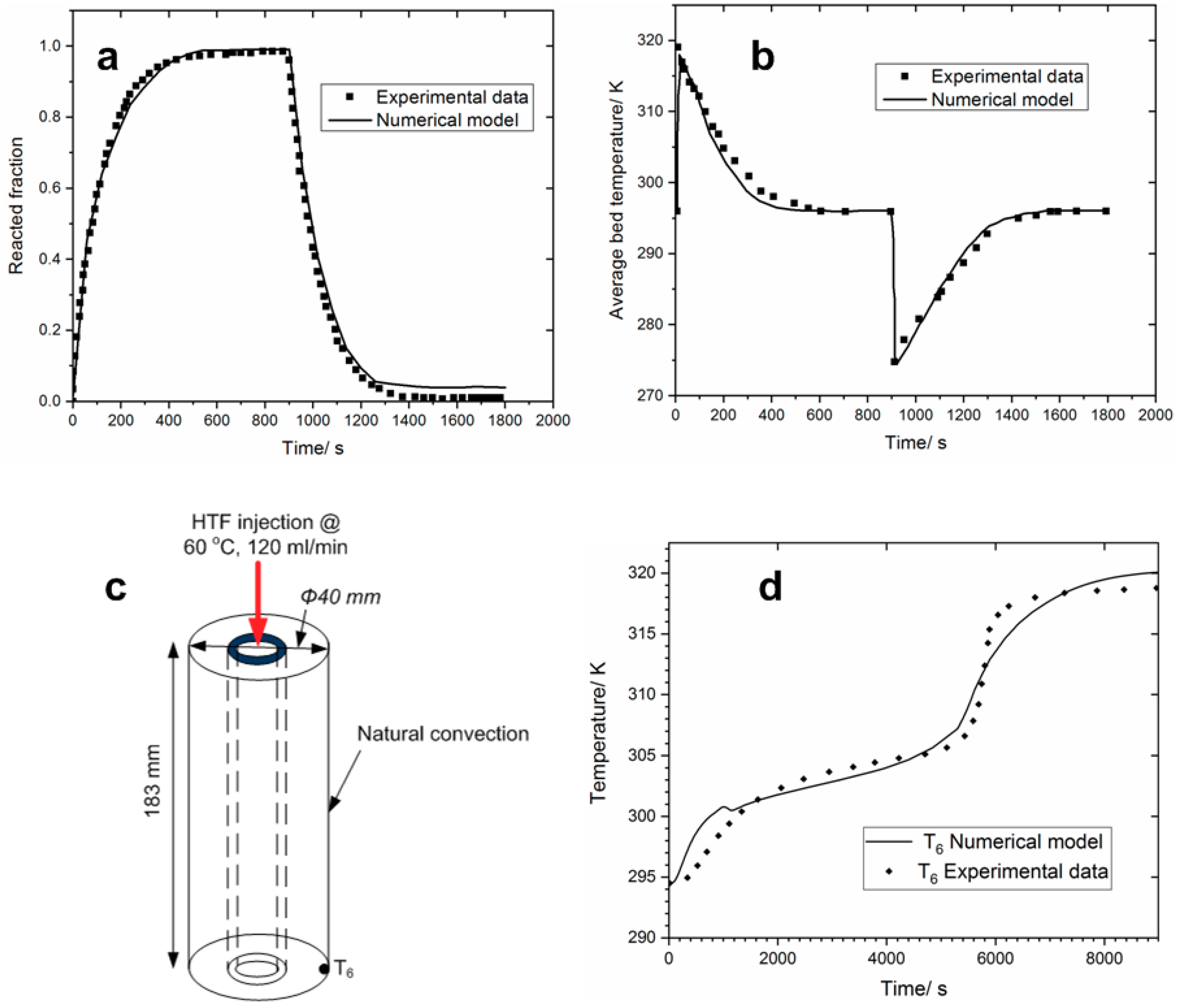
4.1. Model Validation

A two-step model validation was conducted to verify whether the results of our model agreed with the experimental works reported in the literature. In the first step, the numerical model of the metal hydride reactor was validated by comparing it to an experimental work presented by Laurencelle and Goyette [51]. In that work, a small reactor containing 1 g of LaNi5 was hydrogenated/dehydrogenated at 23 °C under 6/0.069 bar H2. Figure 6a,b depict a comparison between the experimental H2 reacted fraction and the mean bed temperature to those determined by the numerical model. As can be seen, an agreement is found which shows that our model can capture with good accuracy the experimental behavior.
The second attempt of validation was done for the PCM proposed model. To this end, the model was compared with experiments done by Siyabi et al. [48]. The schematic of the experimental reactor is depicted in Figure 6c. It consisted of a shell and tube reactor, where a heat transfer fluid flows inside the stainless tube and the PCM is in the shell. The commercial-grade RT35 (Rubitherm Technologies GmbH, Germany) PCM was chosen for the study. The heat charging process was made by injecting a HTF at a constant temperature of 60 °C and a constant flow rate of 120 mL/min. The temperature distribution inside the PCM was monitored by several K-type thermocouples placed in different positions along the vertical direction. Figure 6d compares the experimental temperature change with our numerical model. The relative error of more than 5% was found. This was mainly due to two factors: The uncertainty on the PCM thermo-physical properties; the natural convection was not taken into account, which can be important for a long vertical reactor. Despite these limiting factors, our PCM model captures the melting behavior of the experimental work.

4.2. Effect of PCM Thermo-Physical Properties on the Thermal Energy Storage System

In this study, the role of PCM for internal heat recovery in the two-bed thermochemical storage system was fully emphasized. More specifically, the effect of PCM thermo-physical properties on the performance (in terms of energy storage density, specific power output, and energy storage efficiency) of the TES was investigated. The properties of PCM have been the subject of intensive research since the thermo-physical properties for the same material greatly vary in the literature. The main properties of PCM are the melting temperature Tm, the heat of fusion (latent heat ∆Hpcm), the density of solid/liquid phase, the heat capacity of the solid and liquid phase and finally the transition phase temperature interval ∆Ttr. These properties can vary depending on the nature of PCM. Among low-temperature PCM, paraffin waxes are the most used for low-temperature heat storage, which were selected for this study. Table 2 gives the thermo-physical properties of two commercially available PCM from Rubitherm (RT). The only difference between these two selected materials is the melting point Tm. There is also a slight difference between the liquid density and solid one, which means there is a very negligible volume expansion during its melting.

4.2.1. The Effect of the PCM Melting Temperature Tm

Figure 7 and Figure 8 show the dynamic behavior of the heat storage system during the heat charging/discharging cycle using PCM with different melting temperatures Tm. From Figure 7, the hydrogen reacted fraction and the melting liquid fraction are plotted as a function of time. During the heat charging, while hydrogen content in the HTMH bed (Mg2NiH4, dashed line) decreases, the one in LTMH bed (LaNi5, continue line) increases simultaneously (Figure 7a). The process is reversed during the heat discharging. It is seen that for the PCM RT31, the HTMH bed desorbs 67.2% of its maximum H2 capacity to the LTMH bed, during the heat charging. However, during the heat recovery stage, only 22.6% of H2 flows back to the HTMH bed. This is due to the low equilibrium pressure of the LTMH bed, as its temperature decreases rapidly to 304.9 K (31 °C), see Figure 8a. At that point, H2 pressure in the LTMH bed is 3.06 bar, which is lower than 3.098 bar, the equilibrium H2 pressure in the HTMH bed. Furthermore, the fast decreasing of the temperature of the LTMH-PCM subsystem from Figure 8b suggested that only sensible heat of the PCM played a role during the heat recovery stage. Hence, the low energy recovery efficiency is observed as the PCM is still liquid (Figure 7b) with a liquid fraction of 0.97. By using RT42, it is seen that the H2 inventory can be greatly improved. In effect, during the heat charging, Mg2NiH4 desorbs approximately 67.7% of H2 and absorbs 53.8% during the reverse process. One of the main reasons for this improved performance is that the equilibrium H2 pressure at the melting temperature of Tm = 42 °C is ca. 4.64 bar, which is higher than 3.098 bar. As a result, the LTMH bed not only absorbs sensible heat but also latent heat from the PCM at that temperature. It can be seen from Figure 7b, the PCM solidifies during the heat discharging process and gives up 75.6% of its latent heat.
Figure 9 shows the temperature distribution inside the system at different selected times (1, 30, 60 and 120 min) during the heat charging process. At the initial stage tc = 1 min, the temperature of the HTMH bed rises quickly from room temperature to 623 K which is the industrial waste heat temperature. Meanwhile, as time proceeds, the LTMH bed heats up because of H2 absorption and hot H2 gas coming from the HTMH bed. Besides, the H2 temperature inside the connecting channel as high as that of the HTMH bed. This is the result of the local thermal equilibrium assumption, which states that the hydride material and the H2 gas are at the same temperature. Therefore, the temperature at the entrance of the LTMH bed might always be higher than that in the rest of the bed. Figure 10 depicts the H2 reacted fraction inside the beds and the PCM liquid fraction plotted simultaneously. At the initial stage, the reacted fraction in HTMH bed is α = 1 and that of LTMH is α = 0. Furthermore, the PCM liquid fraction is f = 0, i.e., the PCM is in a solid-state. As time proceeds, H2 depletes from the HTMH bed. The depletion front happens near the reactor wall where the heat transfer is maximum and slowly moves towards the reactor center. In the meantime, H2 is absorbed inside the LTMH at the interface LTMH bed/PCM jacket, where the PCM absorbs the heat generated. Consequently, the PCM liquefies (Note that the PCM liquid fraction increases rapidly as per Figure 7b). Since the temperature at the entrance of LTMH bed is higher than that of remaining part of the bed (As we mentioned earlier), the PCM in that top part of the jacket is completely liquefied (f = 1). At the end of the heat charging process (tc = 120 min), it is seen that the PCM is not completely liquid as a small pocket of solid PCM exists at the bottom corner of the PCM jacket. The same reasoning can be made to explain the spatial distribution of temperature, H2 reacted and PCM liquid fraction inside the system during the heat recovery process which is not presented here.
Figure 11 compares the performance of the heat storage system using the two studied PCMs. The system stored approximatively 333 MJ∙m−3 of energy density, regardless of the melting point of PCMs under specified operating conditions. However, it was discussed above that the melting temperature limits the heat recovery process. Using RT31, the recovery energy density, power output, and energy storage efficiency are 77 MJ∙m−3, 43.92 W∙(kg-Mg2Ni)−1, and 23.43%, respectively. On the other hand, the utilization of RT42 greatly boosts these performance indicators to 173.29 MJ∙m−3, 98 W∙(kg-Mg2Ni)−1 and 52.03% for energy density, power output, and energy storage efficiency, respectively. Given the size of the heat storage system and the properties of the HTMH (Mg2NiH4), the maximum theoretical energy density can be assessed due to the chemical reaction using Q c , m a x = w t ( 1 ε ) ρ HTMH Δ H HTMH V HTMH / ( M H 2 · V s ) . The waste-heat recovery efficiency of 60.8% can be obtained when taking into account the energy density of 285 MJ∙m−3 outlined on the graph by the red line.
A parametric study was conducted on the storage system to see which other thermos-physical properties of the PCM improve the performance of the storage system in terms of energy density, efficiency and power output. To this end, the RT42 was selected for the following discussion. Besides, one parameter is varied at a time while others are kept fixed.

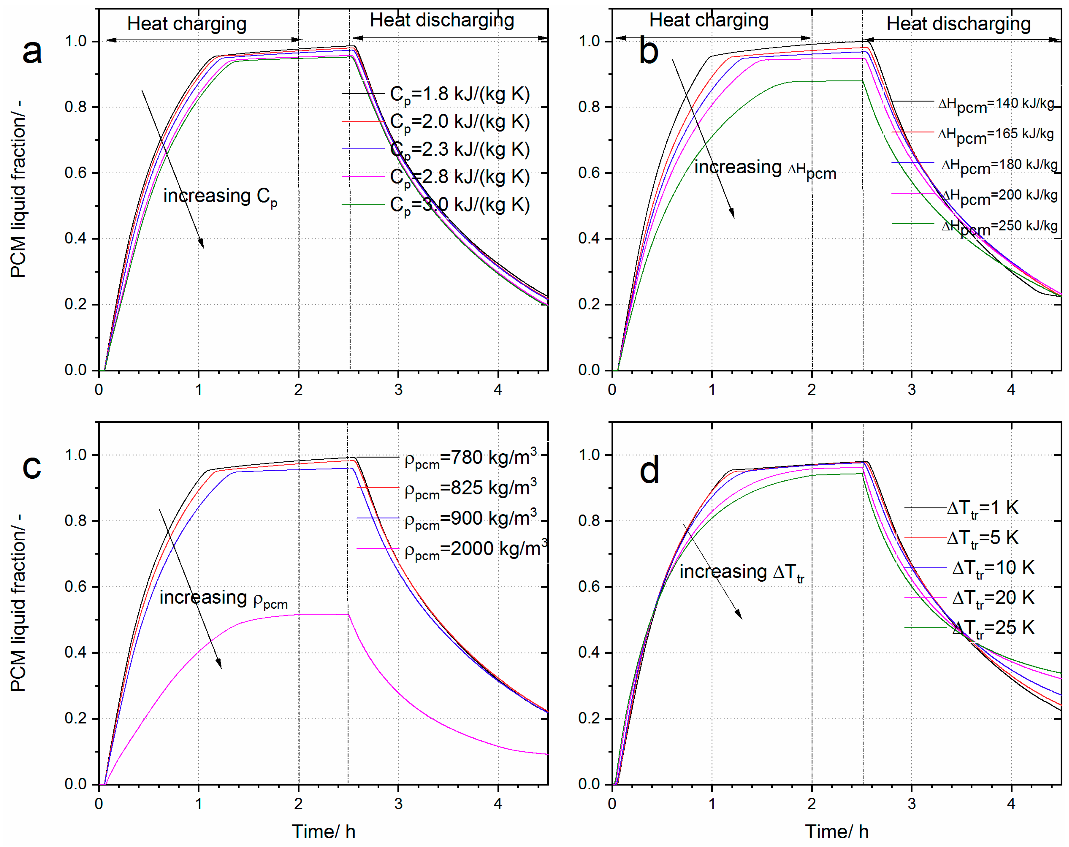
4.2.2. The Effect of Cp, ∆Ttr, ∆Hpcm and ρpcm on the Performance of the Heat Storage System

The simultaneous discussion of the effect of these parameters on the performance stems from the fact that these parameters affect the thermal inertia of the phase change by the expression Equation (25):
( ρ C p ) e f f = ρ ¯ p c m ( C p + Δ H p c m Δ f Δ T t r )
where the density and the heat capacity are the averaged value of that in solid and liquid form. Based on the energy balance equation, the increase of the thermal inertia of a media generally leads to a temperature gain limitation. These parameters can also be called temperature dampers or ballast. Therefore, increasing the average density, the heat capacity, the latent heat of fusion on the one hand and decreasing the phase transition interval, on the other hand, decreases the final equilibrium temperature of the system LTMH-PCM. This reduction of the equilibrium temperature promotes the heat-charging process while deteriorating the heat discharging process. However, the efficient performance of the system is ruled by the temperature difference (which affects the equilibrium H2 pressure according to Van’t Hoff diagram) between the HTMH bed and LTMH-PCM. To quantitatively assess this effect, Figure 12 and Figure 13 depict the effect of each parameter on the liquid fraction and the average PCM temperature. From Figure 13, it can be seen that after the heat charging and storage process, the final temperatures (at tc = 2.5 h) are decreased when increasing one of these temperature dampers parameters (Cp, ∆Hpcm, ρpcm). For instance, in Figure 13a, it is observed that when a PCM with a heat capacity of 1800 J∙kg−1∙K−1 is selected, the PCM temperature at 2.5 h is 333 K. As its heat capacity increases to 2800 J∙kg−1∙K−1, its final temperature drops to ca. 327 K. This trend is more remarkable with the increase of PCM density as can be seen in Figure 13b. Table 3 summarizes the effects of the aforementioned parameters on the performance indicators of the heat storage system. The increasing of the heat capacity, the latent heat of fusion and the density has a positive effect on the energy storage density with a maximum deviation of 4.23, 10.51 and 14.22%. These findings corroborate the results presented by [45], in which it was demonstrated that high latent heat of fusion and PCM mass promoted the hydrogen storage performance in the LTMH bed. However, the trend is reversed when considering their effect on the energy recovery efficiency. On the other hand, it is noticed that these thermo-physical parameters have a little impact on the specific power output. On the contrary, the transition temperature zone, ∆Ttr leads to a decrease of either performance indicator, although the decrease is limited to 5%.

4.3. The Effect of Design Parameters

While the previous parameters are intrinsic properties of a PCM which are not easily adjustable, the engineering properties, such as the PCM jacket volume and PCM thermal conductivity, are tunable. One of the most discussed routes of improving the thermal conductivity of PCM is by the addition of materials with high thermal conductivity, such as metal foams [22], fins [25] or carbon-based materials (graphite, carbon nanotube) [52,53]. Although the addition of these materials results in the change of not only the thermal conductivity but also the overall PCM density and heat capacity, a mere variation is studied here of the PCM thermal conductivity. As can be seen from Figure 14a,c, the effects of thermal conductivity increase the liquid fraction and PCM temperature, respectively. By increasing the thermal conductivity from 0.2 to 5 W∙m−1∙K−1, the liquid fraction increases rapidly. For example, increasing the thermal conductivity to 5 W∙m−1∙K−1, the PCM liquefies in less than 40 min, which reflects the high heat transfer between the LTMH bed and the PCM jacket. However, a further increase of thermal conductivity to 10 W∙m−1∙K−1 brings about a minute change on the performance. From Table 3, the power output increases tremendously by 113%, as the PCM thermal conductivity is augmented from 0.2 to 10 W∙m−1∙K−1. Moreover, from Table 3, other performance indicators, such as heat charging density and energy storage efficiency, increased accordingly by 24% and 72%, respectively.
Figure 14b,d show the effect of increasing the volume of PCM on the melting fraction and the temperature. As can be seen from the figure, increasing the PCM volume to a certain point becomes detrimental to the heat storage system. More PCM behaves as a temperature damper (see Figure 14d), since the equilibrium temperature of the system LTMH-PCM decreases, which in turn decreases the heat recovery performance. However, it can be seen from Table 3 that there is an optimal PCM volume for which the performance is maximum. In this case, a volume ratio of 2.74 between the PCM jacket and LTMH bed is the optimal parameter.

5. Conclusions

The recovery of industrial waste heat is among the popular research topics in order to improve energy efficiency and utilization in the industrial sector. Therefore, efficient latent heat-based thermal energy storage systems were extensively studied in the literature. In this work, a combined two-tank latent and thermochemical heat storage system was proposed and analyzed in detail, with the main objective of assessing the impact of integrating a PCM for internal heat recovery. The results showed that the selection of the PCM is of great importance. Among the thermo-physical properties of the PCM, it was shown that by the aid of the Van’t hoff diagram, the melting temperature Tm is the first criterion of PCM selection to allow the heat storage system to function properly. Using a sensitivity analysis, the increase of PCM thermal conductivity strongly ameliorated the energy storage density, the specific power output and the energy recovery efficiency by 24.01%, 113.32%, and 72%, respectively. Other properties, such as melting temperature range, latent heat of fusion, specific heat capacity and density although equally important brought about a relatively small variation on the heat storage performance by less than 15 %. Although this study clearly shows the impact of integrating a PCM jacket on the performance of a two-tank thermochemical heat storage system, it should be noted this configuration is not fully optimized. The system can be optimized by inserting PCM channels inside the metal hydride beds, thereby improving the heat transfer between the two media. This will be the subject of future work.

Author Contributions

Conceptualization, S.N.N. and I.T.; methodology, S.N.N., I.T. and M.L.; software, S.N.N., I.T. and M.L.; validation, S.N.N.; formal analysis, S.N.N. and M.L.; writing—original draft preparation, S.N.N.; writing—review and editing, S.N.N., I.T. and M.L.

Funding

This research was funded by the Department of Science and Technology (DST) in South Africa; project KP6-S02 “Metal Hydride Hydrogen Compressors and Heat Pumps” and EU Horizon 2020/RISE project “Hydrogen fuelled utility vehicles and their support systems utilising metal hydrides—HYDRIDE4MOBILITY, Project Number: 778307.

Acknowledgments

S. Nyallang Nyamsi and M. Lototskyy acknowledge the financial incentive from the Department of Science and Technology (DST) in South Africa (project KP6-SO2). I. Tolj, M. Lototskyy and S. Nyallang Nyamsi acknowledge financial support from EU Horizon 2020/RISE project “Hydrogen fuelled utility vehicles and their support systems utilising metal hydrides—HYDRIDE4MOBILITY” (project number: 778307).

Conflicts of Interest

The authors declare no conflict of interest.

Nomenclature

ASurface area (m2)
CHeat capacity (J·mol−1∙K−1)
EActivation energy (J·mol−1)
fpressure-dependent function, PCM melting fraction
gconversion fraction-dependent function
hoilconvective heat transfer coefficient (W·m−2· K−1)
HTFheat transfer fluid
HTMHhigh temperature metal hydride
ΔHheat of reaction (J·mol−1)
krate constant (s−1)
Lreactor length (m)
LTMHlow temperature metal hydride
Mmolecular weight (g·mol−1)
ppressure (bar)
PCMphase change material
Qheat flux (J)
rradius (m)
Runiversal gas constant (8.314 J·mol−1·K−1)
ΔSentropy of reaction (J·mol−1·K−1)
Sheat transfer surface (m2)
ttime (s)
ΔTtemperature range of phase transition
Vvelocity (m·s−1), reactor volume (m3)
wthydrogen storage capacity (%)
Greek letters
αconversion fraction
εporosity
γ thermal inertia
ρ material density (kg·m−3)
ηenergy storage efficiency
λthermal conductivity (W·m−1·K−1)
μdynamic viscosity (Pa·s)
Subscripts
aabsorption
ccharging
ddesorption, discharging
effeffective
eqequilibrium
iinlet
ffluid
ggas
lliquid
mmelting
MHmetal hydride
mixmixture
ooutlet
ononset
ssystem, solid
trtransition
wwall

References

  1. Taymaz, I. An experimental study of energy balance in low heat rejection diesel engine. Energy 2006, 31, 364–371. [Google Scholar] [CrossRef]
  2. Chan, C.W.; Ling-Chin, J.; Roskilly, A.P. A review of chemical heat pumps, thermodynamic cycles and thermal energy storage technologies for low grade heat utilization. Appl. Therm. Eng. 2013, 50, 1257–1273. [Google Scholar] [CrossRef]
  3. Kwak, D.H.; Binns, M.; Kim, J.K. Integrated design and optimization of technologies for utilizing low grade heat in process industries. Appl. Energy 2014, 131, 307–322. [Google Scholar] [CrossRef]
  4. Poudel, B.; Hao, Q.; Ma, Y.; Lan, Y.C.; Minnich, A.; Yu, B.; Yan, X.; Wang, D.; Muto, A.; Vashaee, D.; et al. High-thermoelectric performance of nanostructured bismuth antimony telluride bulk alloys. Science 2008, 320, 634–638. [Google Scholar] [CrossRef] [PubMed]
  5. Singh, D.V.; Pedersen, E. A review of waste heat recovery technologies for maritime applications. Energy Convers Manag. 2016, 111, 315–328. [Google Scholar] [CrossRef]
  6. Wang, T.; Luan, W.; Wang, W.; Tu, S.T. Waste heat recovery through plate heat exchanger based thermoelectric generator system. Appl. Energy 2014, 136, 860–865. [Google Scholar] [CrossRef]
  7. Gou, X.; Xiao, H.; Yang, S. Modeling experimental study and optimization on low temperature waste heat thermoelectric generator system. Appl. Energy 2010, 87, 3131–3136. [Google Scholar] [CrossRef]
  8. Yamankaradeniz, N.; Bademlioglu, A.H.; Kaynakli, O. Performance assessments of an organic Rankine cycle with internal heat exchanger based on exergetic approach. J. Energy Resour. Technol. 2018, 140, 102001–102008. [Google Scholar] [CrossRef]
  9. Bademlioglu, A.H.; Canbolat, A.S.; Yamankaradeniz, N.; Kaynakli, O. Investigation of parameters affecting Organic Rankine Cycle efficiency by using Taguchi and ANOVA methods. Appl. Therm. Eng. 2018, 145, 221–228. [Google Scholar] [CrossRef]
  10. Song, J.; Song, Y.; Gu, C.W. Thermodynamic analysis and performance optimization of an Organic Rankine Cycle (ORC) waste heat recovery system for marine diesel engines. Energy 2015, 82, 976–985. [Google Scholar] [CrossRef]
  11. Larsen, U.; Pierobon, L.; Haglind, F.; Gabrielii, C. Design and optimisation of organic Rankine cycles for waste heat recovery in marine applications using the principles of natural selection. Energy 2013, 55, 803–812. [Google Scholar] [CrossRef] [Green Version]
  12. Miró, L.; Gasia, J.; Cabeza, L.F. Thermal energy storage (TES) for industrial waste heat (IWH) recovery: A review. Appl. Energy 2016, 179, 284–301. [Google Scholar] [CrossRef] [Green Version]
  13. Magro, F.D.; Jimenez-Arreola, M.; Romagnoli, A. Improving energy recovery efficiency by retrofitting a PCM-based technology to an ORC system operating under thermal power fluctuations. Appl. Energy 2017, 208, 972–985. [Google Scholar] [CrossRef]
  14. Yu, X.; Li, Z.; Lu, Y.; Huang, R.; Roskilly, A.P. Investigation of organic Rankine cycle integrated with double latent thermal energy storage for engine waste heat recovery. Energy 2019, 170, 1098–1112. [Google Scholar] [CrossRef]
  15. Pandiyarajan, V.; Chinnappandian, M.; Raghavan, V.; Velraj, R. Second law analysis of a diesel engine waste heat recovery with a combined sensible and latent heat storage system. Energy Policy 2011, 39, 6011–6020. [Google Scholar] [CrossRef]
  16. Ortega-Fernández, I.; Rodríguez-Aseguinolaza, J. Thermal energy storage for waste heat recovery in the steelworks: The case study of the REslag project. Appl. Energy 2019, 237, 708–719. [Google Scholar] [CrossRef]
  17. Gopal, K.N.; Subbarao, R.; Pandiyarajan, V.; Velraj, R. Thermodynamic analysis of a diesel engine integrated with a PCM based energy storage system. Int. J. Thermodyn. 2010, 13, 15–21. [Google Scholar]
  18. Wang, W.; Guo, S.; Li, H.; Yan, J.; Zhao, J.; Li, X.; Ding, J. Experimental study on the direct/indirect contact energy storage container in mobilized thermal energy system (M-TES). Appl. Energy 2014, 119, 181–189. [Google Scholar] [CrossRef]
  19. Guo, S.P.; Zhao, J.; Wang, W.L.; Yan, J.Y.; Jin, G.; Wang, X.T. Techno-economic assessment of mobilized thermal energy storage for distributed users: A case study in China. Appl. Energy 2017, 194, 481–486. [Google Scholar] [CrossRef]
  20. Li, H.; Wang, W.; Yan, J.; Dahlquist, E. Economic assessment of the mobilized thermal energy storage (M-TES) system for distributed heat supply. Appl. Energy 2013, 104, 178–186. [Google Scholar] [CrossRef]
  21. Lizana, J.; Chacartegui, R.; Barrios-Padura, A.; Valverde, J.M. Advances in thermal energy storage materials and their applications towards zero energy buildings: A critical review. Appl. Energy 2017, 203, 219–239. [Google Scholar] [CrossRef]
  22. Cui, H.T. Experimental investigation on the heat charging process by paraffin filled with high porosity copper foam. Appl. Therm. Eng. 2012, 39, 26–28. [Google Scholar] [CrossRef]
  23. Merlin, K.; Soto, J.; Delaunay, D.; Traonvouez, L. Industrial waste heat recovery using an enhanced conductivity latent heat thermal energy storage. Appl. Energy 2016, 183, 491–503. [Google Scholar] [CrossRef]
  24. Py, X.; Olives, R.; Mauran, S. Paraffin/porous-graphite-matrix composite as a high and constant power thermal storage material. Int. J. Heat Mass Transf. 2001, 44, 2727–2737. [Google Scholar] [CrossRef]
  25. Yang, X.; Lu, Z.; Bai, Q.; Zhang, Q.; Jin, L.; Yan, J. Thermal performance of a shell-and-tube latent heat thermal energy storage unit: Role of annular fins. Appl. Energy 2017, 202, 558–570. [Google Scholar] [CrossRef]
  26. Jouhara, H.; Almahmoud, S.; Chauhan, A.; Delpech, B.; Bianchi, G.; Tassou, S.A.; Llera, R.; Lago, F.; Arribas, J.J. Experimental and theoretical investigation of a flat heat pipe heat exchanger for waste heat recovery in the steel industry. Energy 2017, 141, 1928–1939. [Google Scholar] [CrossRef]
  27. Ma, H.; Yin, L.; Shen, X.; Lu, W.; Sun, Y.; Zhang, Y.; Deng, N. Experimental study on heat pipe assisted heat exchanger used for industrial waste heat recovery. Appl. Energy 2016, 169, 177–186. [Google Scholar] [CrossRef]
  28. Li, T.X.; Xu, J.X.; Yan, T.; Wang, R.Z. Development of sorption thermal battery for low-grade waste heat recovery and combined cold and heat energy storage. Energy 2016, 107, 347–359. [Google Scholar] [CrossRef]
  29. Verde, M.; Harby, K.; de Boer, R.; Corber, J.M. Performance evaluation of a waste-heat driven adsorption system for automotive air-conditioning: Part I: Modeling and experimental validation. Energy 2016, 116, 526–538. [Google Scholar] [CrossRef]
  30. Gao, P.; Wang, L.W.; Wang, R.Z.; Zhang, X.F.; Li, D.P.; Liang, Z.W.; Cai, A.F. Experimental investigation of a MnCl2/CaCl2-NH3 two-stage solid sorption freezing system for a refrigerated truck. Energy 2016, 103, 16–26. [Google Scholar] [CrossRef]
  31. Lu, Y.Z.; Wang, R.Z.; Jianzhou, S.; Xu, Y.X.; Wu, J.Y. Practical experiments on an adsorption air conditioner powered by the exhausted heat from a diesel locomotive. Appl. Therm. Eng. 2004, 24, 1051–1059. [Google Scholar] [CrossRef]
  32. Jiang, L.; Wang, L.W.; Wang, R.Z.; Zhu, F.Q.; Lu, Y.J.; Roskilly, A.P. Experimental investigation on an innovative resorption system for energy storage and upgrade. Energy Convers. Manag. 2017, 138, 651–658. [Google Scholar] [CrossRef] [Green Version]
  33. Jiang, L.; Roskilly, A.P.; Wang, R.Z.; Wang, L.W.; Lu, Y.J. Analysis on innovative modular sorption and resorption thermal cell for cold and heat cogeneration. Appl. Energy 2017, 204, 767–779. [Google Scholar] [CrossRef] [Green Version]
  34. Qin, F.; Chen, J.P.; Lu, M.Q.; Chen, Z.J.; Zhou, Y.M.; Yang, K. Development of a metal hydride refrigeration system as an exhaust gas-driven automobile air conditioner. Renew. Energy 2007, 32, 2034–2052. [Google Scholar] [CrossRef]
  35. Yang, F.S.; Wang, G.X.; Zhang, Z.X.; Rudolph, V. Investigation on the influences of heat transfer enhancement measures in a thermally driven metal hydride heat pump. Int. J. Hydrogen Energy 2010, 35, 9725–9735. [Google Scholar] [CrossRef]
  36. Klein, H.P.; Groll, M. Development of a two-stage metal hydride system as topping cycle in cascading sorption systems for cold generation. Appl. Therm. Eng. 2002, 22, 631–639. [Google Scholar] [CrossRef]
  37. Isselhorst, A.; Groll, M. Two-stage metal hydride heat transformer laboratory model. J. Alloy. Comp. 1995, 231, 888–894. [Google Scholar] [CrossRef]
  38. Bogdanovic, B.; Ritter, A.; Spliethoff, B. A process steam generator based on the high temperature magnesium hydride/magnesium heat storage system. Int. J. Hydrogen Energy 1995, 20, 811–822. [Google Scholar] [CrossRef]
  39. Reiser, A.; Bogdanovic, B.; Schlichte, K. The application of Mg-based metal hydrides as heat energy storage systems. Int. J. Hydrogen Energy 2000, 25, 425–430. [Google Scholar] [CrossRef]
  40. Nyallang, S.N.; Lototskyy, M.; Tolj, I. Selection of metal hydrides-based thermal energy storage: Energy storage efficiency and density targets. Int. J. Hydrogen Energy 2018, 43, 22568–22583. [Google Scholar]
  41. Corgnale, C.; Hardy, B.; Motyka, T.; Zidan, R.; Teprovich, J.; Peters, B. Screening analysis of metal hydride based thermal energy storage systems for concentrating solar power plants. Renew. Sustain. Energy Rev. 2014, 38, 821–833. [Google Scholar] [CrossRef]
  42. Yang, F.; Zhen Wu, Z.; Liu, S.; Zhang, Y.; Geoff Wang, G.; Zhang, Z.; Wang, Y. Theoretical formulation and performance analysis of a novel hydride heat Pump(HHP) integrated heat recovery system. Energy 2018, 163, 208–220. [Google Scholar] [CrossRef]
  43. Mellouli, S.; Abhilash, E.; Askri, F.; Nasrallah, S.B. Integration of thermal energy storage unit in a metal hydride hydrogen storage tank. Appl. Therm. Eng. 2016, 102, 1185–1196. [Google Scholar] [CrossRef]
  44. Darzi, A.A.R.; Afrouzi, H.H.; Moshfegh, A.; Farhadi, M. Absorption and desorption of hydrogen in long metal hydride tank equipped with phase change material jacket. Int. J. Hydrogen Energy 2016, 41, 9595–9610. [Google Scholar] [CrossRef]
  45. Tong, L.; Xiao, J.; Bénard, P.; Chahine, R. Thermal management of metal hydride hydrogen storage reservoir using phase change materials. Int. J. Hydrogen Energy 2019, 44, 21055–21066. [Google Scholar] [CrossRef]
  46. Nyamsi, S.N.; Yang, F.; Zhang, Z. An optimization study on the finned tube heat exchanger used in hydride hydrogen storage system- analytical method and numerical simulation. Int. J. Hydrogen Energy 2012, 37, 16078–16092. [Google Scholar] [CrossRef]
  47. Longeon, M.; Soupart, A.; Fourmigué, J.F.; Bruch, A.; Marty, P. Experimental and numerical study of annular PCM storage in the presence of natural convection. Appl. Energy 2013, 112, 175–184. [Google Scholar] [CrossRef]
  48. Siyabi, I.A.; Khanna, S.; Mallick, T.; Sundaram, S. An experimental and numerical study on the effect of inclination angle of phase change materials thermal energy storage system. J. Energy Storage 2019, 23, 57–68. [Google Scholar] [CrossRef]
  49. Chiu, J.N.W.; Martin, V. Submerged finned heat exchanger latent heat storage design and its experimental verification. Appl. Energy 2012, 93, 507–513. [Google Scholar] [CrossRef]
  50. Miled, A.; Mellouli, S.; Ben Maad, H.; Askri, F. Improvement of the performance of metal hydride pump by using phase change heat exchanger. Int. J. Hydrogen Energy 2017, 42, 26343–26361. [Google Scholar] [CrossRef]
  51. Laurencelle, F.; Goyette, J. Simulation of heat transfer in metal hydride reactor with aluminum foam. Int. J. Hydrogen Energy 2007, 32, 2957–2964. [Google Scholar] [CrossRef]
  52. Wang, J.F.; Xie, H.Q.; Xin, Z.; Li, Y.; Chen, L.F. Enhancing thermal conductivity of palmitic acid based phase change materials with carbon nanotubes as fillers. Sol. Energy 2010, 84, 339–344. [Google Scholar] [CrossRef]
  53. Jun, F.K.; Yuichi, H.; Yoshi, M.; Osamu, M. Improvement of thermal characteristics of latent heat thermal energy storage units using carbon-fiber brushes: Experiments and modeling. Int. J. Heat Mass Transf. 2003, 46, 4513–4525. [Google Scholar]
Figure 1. Conventional industrial waste heat sources and recovery technologies.
Energies 12 03949 g001
Figure 2. Two-tank thermochemical thermal energy storage (TES) utilizing metal hydrides pair: (a) conventional system; (b) Proposed storage system using phase change materials (PCM) for internal heat recovery.
Energies 12 03949 g002
Figure 3. Working principle of the combined latent and thermochemical heat storage system: Van’t Hoff diagram.
Energies 12 03949 g003
Figure 4. Axis-symmetric (2-D) computational volume.
Energies 12 03949 g004
Figure 5. Typical PCM heat capacity profile.
Energies 12 03949 g005
Figure 6. Model validation against experimental data (a) average reacted fraction (b) average bed temperature (c) Schematic of the PCM reactor and experimental condition (d) PCM temperature at T6 [48].
Energies 12 03949 g006
Figure 7. The influence of PCM melting point on the temporal profile of: (a) Average H2 reacted fraction, (b) PCM melting fraction.
Energies 12 03949 g007
Figure 8. The influence of PCM melting point on the temporal profile of: (a) average beds temperature, (b) PCM mean temperature.
Energies 12 03949 g008
Figure 9. Temperature spatial distribution in the control volume at selected time (1, 30, 60 and 120 min) during the heat charging.
Energies 12 03949 g009
Figure 10. H2 reacted fraction/PCM liquid fraction spatial distribution in the control volume at selected time (1, 30, 60 and 120 min) during the heat charging.
Energies 12 03949 g010
Figure 11. The influence of the PCM melting point on the performance of heat storage system: energy density and specific power output, energy storage efficiency.
Energies 12 03949 g011
Figure 12. The influence of PCM thermophysical properties on the PCM melting fraction: (a) Heat capacity (b) the latent heat of fusion, (c) the PCM density, (d) the phase transition temperature range.
Energies 12 03949 g012
Figure 13. The influence of PCM thermophysical properties on the PCM temperature: (a) Heat capacity (b) the latent heat of fusion, (c) the PCM density, (d) the phase transition temperature range.
Energies 12 03949 g013
Figure 14. The influence of PCM thermophysical properties on the PCM temperature: (a) Heat capacity (b) the latent heat of fusion, (c) the PCM density, (d) the phase transition temperature range.
Energies 12 03949 g014
Table 1. Physical parameters used in the model simulation [40,44,50].
Parameter/UnitMg2NiLaNi5
Enthalpy of formation/kJ∙mol−164.530.5
Entropy of formation/J∙mol−1∙K−1122.2108
Activation energy, abs-des/kJ∙mol−152.20/63.4621.17/16.47
Rate constant abs-des/s−1175/5452.259.18/9.57
Density/kg∙m−332008400
Specific heat, M-MH/J∙kg−1∙K−1697419
Hydrogen capacity/wt.% 3.61.39
Porosity0.50.5
Permeability/m2 1 × 10−121 × 10−12
Effective thermal conductivity/W∙m−1∙K−111
Hydride thickness/m0.0150.015
H2 filter radius, r0/m0.0030.003
Reactor length LMH/m0.450.45
Table 2. Thermo-physical properties of Rubitherm-based phase change materials [21].
Parameter/UnitRT31RT42
Melting temperature Tm/°C3142
Density: solid-liquid/kg∙m−3880–760880–760
Thermal conductivity/W∙m−1∙K−10.20.2
Specific heat, Cp/J∙kg−1∙K−120002000
Latent heat of fusion, ∆Hpcm/kJ∙kg−1165165
Volumetric energy density/MJ∙m−3145145
PCM jacket radius/m0.040.04
Reactor length Lpcm/m0.470.47
Table 3. The effect of thermo-physical properties of PCM and design parameters on the performance indicators of the heat storage system.
Parameters-Performance Indicators
Thermo-physical propertiesRangeEnergy density/MJ∙m−3Power output/W∙kg−1-Mg2NiEnergy recovery efficiency/%
Cp/J∙kg−1∙K−11800328.8997.5252.42
2000334.1297.9151.81
2300337.3898.3451.15
3000342.8197.7650.41
Max deviation4.23%0.8%−3.83%
ρpcm/kg∙m−3780323.2796.7352.9
900340.1398.1350.71
2000369.2698.8447.32
Max deviation14.22%2.18%−10.54%
Hpcm/kJ∙kg−1140315.8494.8953.11
180337.4198.0551.66
200342.0697.7850.53
250349.0697.1649.20
Max deviation10.51%3.33%−7.36%
Ttr/K1333.0697.9151.97
5332.1897.4052.71
10331.1796.8151.68
20329.3592.7149.76
Max deviation−1.11%−5.31%−4.25%
Design parametersRange-
Vpcm/VLTMH1.71343.9259.3347.36
2.79345.2183.8453.05
4.03331.2798.1452.37
5.44285.9191.9146.73
Max deviation−16.86%54.91%13.34%
λpcm/W∙m−1∙K−10.2267.8851.4233.93
1333.6998.1151.98
2332.54105.3055.98
5331.05107.6257.47
10332.12109.6758.37
Max deviation23.98%113.28%72.03%

