3.1. Turbines
The objective of the paper being to assess and compare the power performances of the Tupperwave device against a conventional OWC, both devices are equipped with the state-of-the-art turbines.
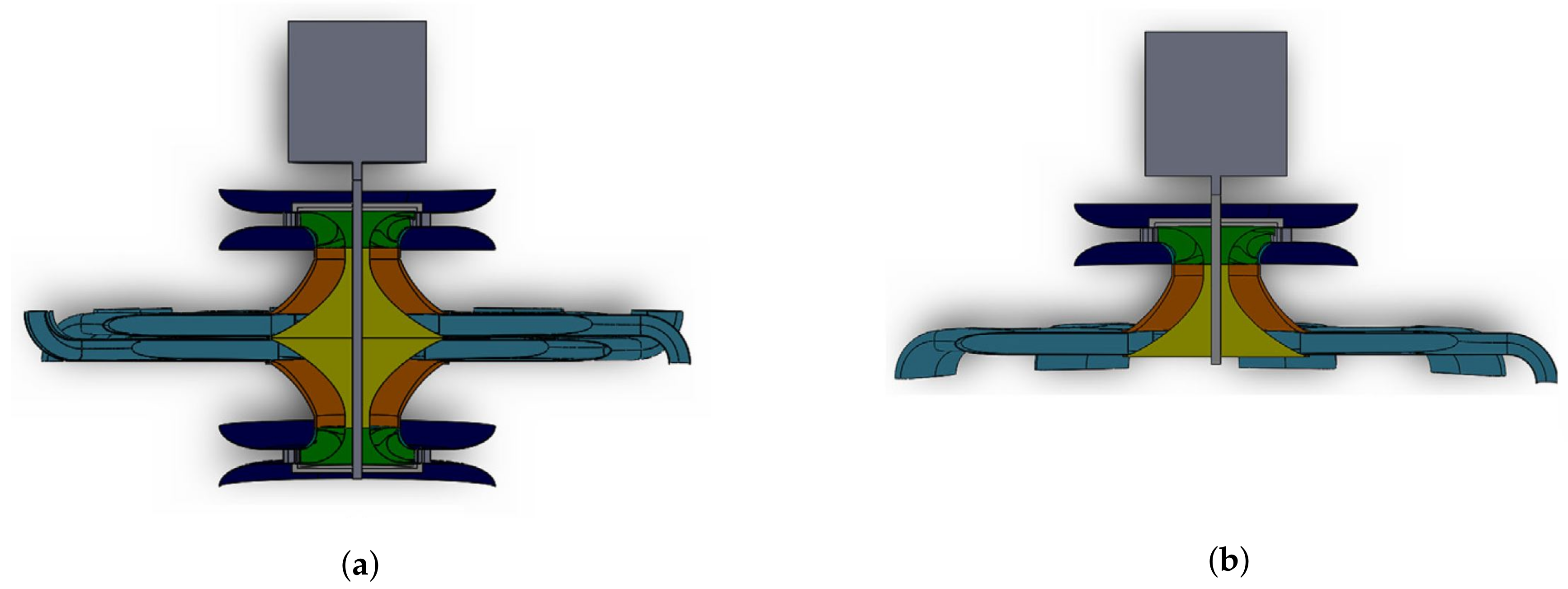
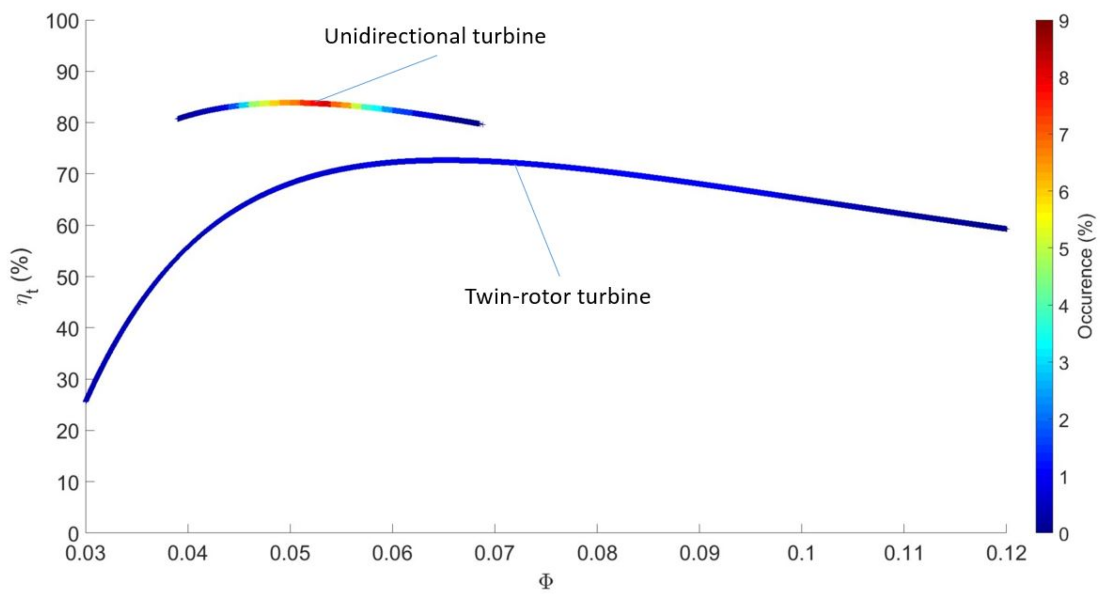
The twin-rotor turbine, displayed in
Figure 6a, is among the most efficient self-rectifying turbines [
3]. It uses the idea that a bidirectional flow can be harnessed by two conventional air turbines in parallel: It consists on a pair of conventional radial-inflow rotors mounted on the same shaft in opposite direction, complemented by the corresponding guide vane rows and by a two-position cylindrical valve which, according to the flow direction, orientates the flow through one rotor or the other [
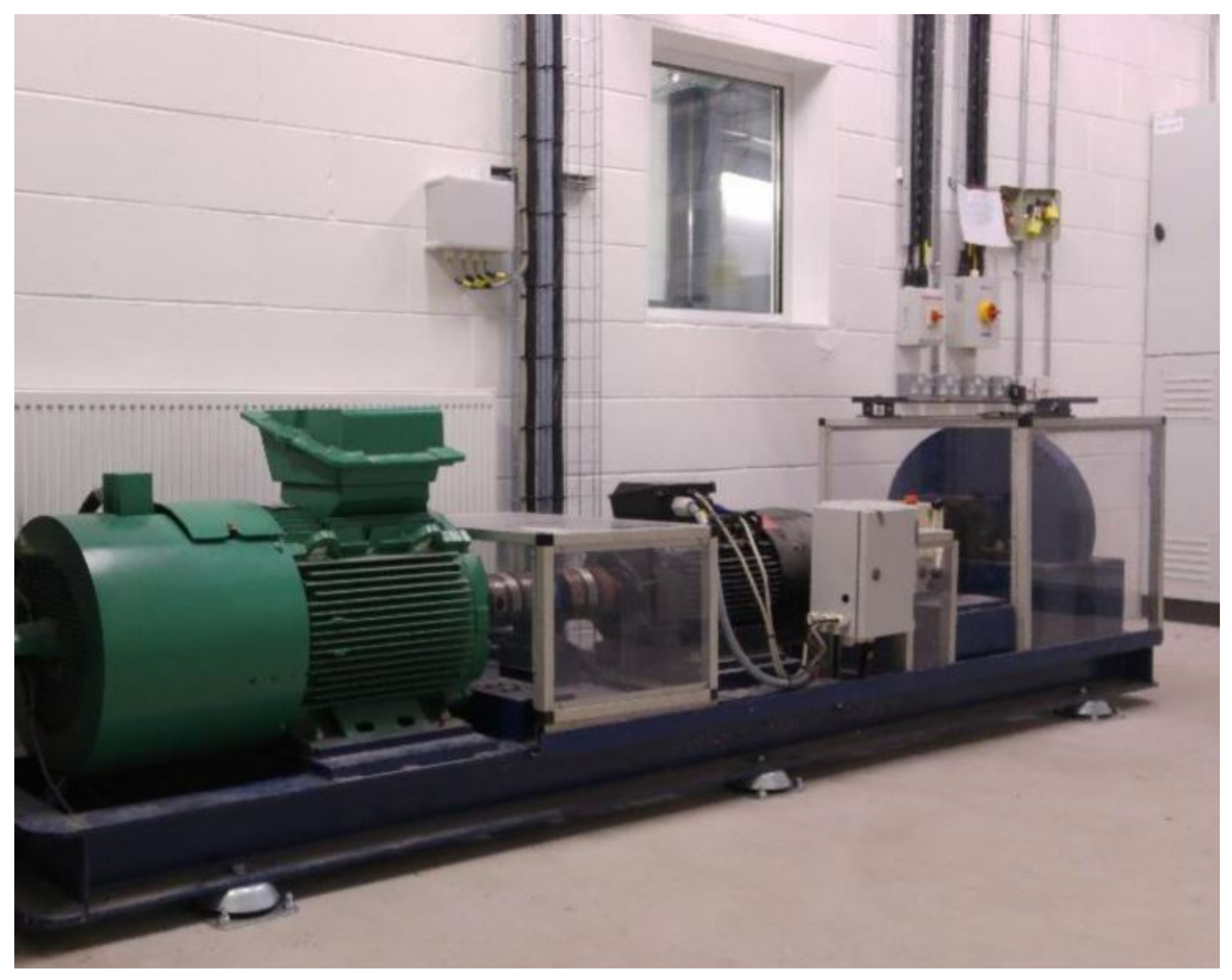
27]. At all times, one rotor is driven by the air flow, while the other spins in no flow. The latter creates windage losses due to aerodynamic drag. Due to its symmetry, half of the turbine was built at model scale in [
5] in order to assess its performance experimentally (
Figure 6b). The resulting unidirectional single-rotor radial inflow unidirectional turbine was tested and the polynomial functions
and
relating the dimensionless coefficients were established. The experimental assessment of the windage losses allowed the establishment of the twin-rotor turbine dimensionless coefficients.
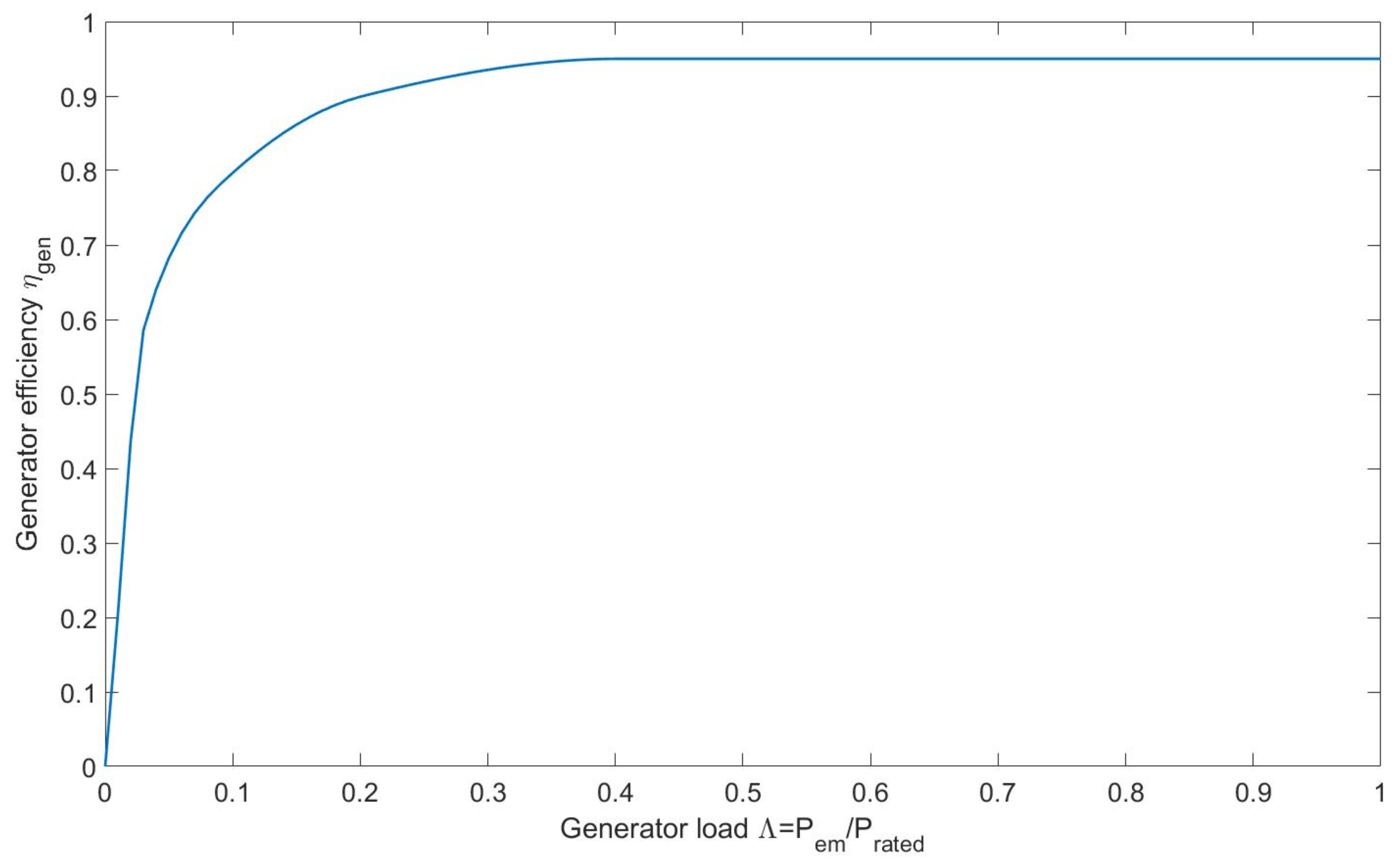
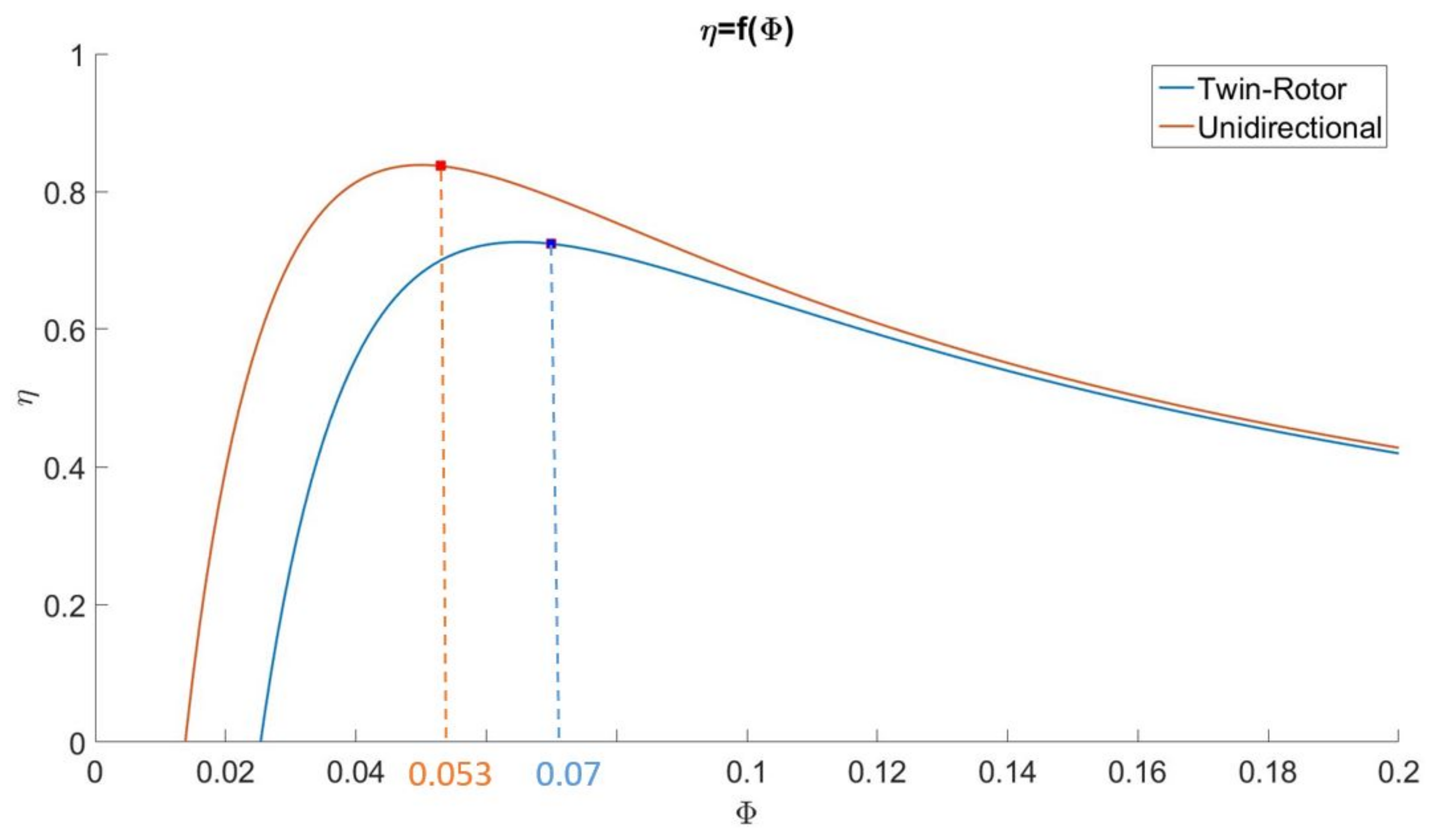
In this paper, the conventional OWC and the Tupperwave device are, respectively, equipped with the twin-rotor turbine and the corresponding single-rotor unidirectional turbine. Both turbines are therefore very similar and based on the same aerodynamic design. The unidirectional turbine is, however, less mechanically complex with no need for the fast-acting and electrically activated two-position valve. Moreover, due to the windage losses, the twin-rotor turbine is less efficient than the unidirectional turbine: It reaches 72.7% while the unidirectional turbine reaches 83.9%. Their total-to-static efficiencies in constant flow condition are compared in
Figure 7.
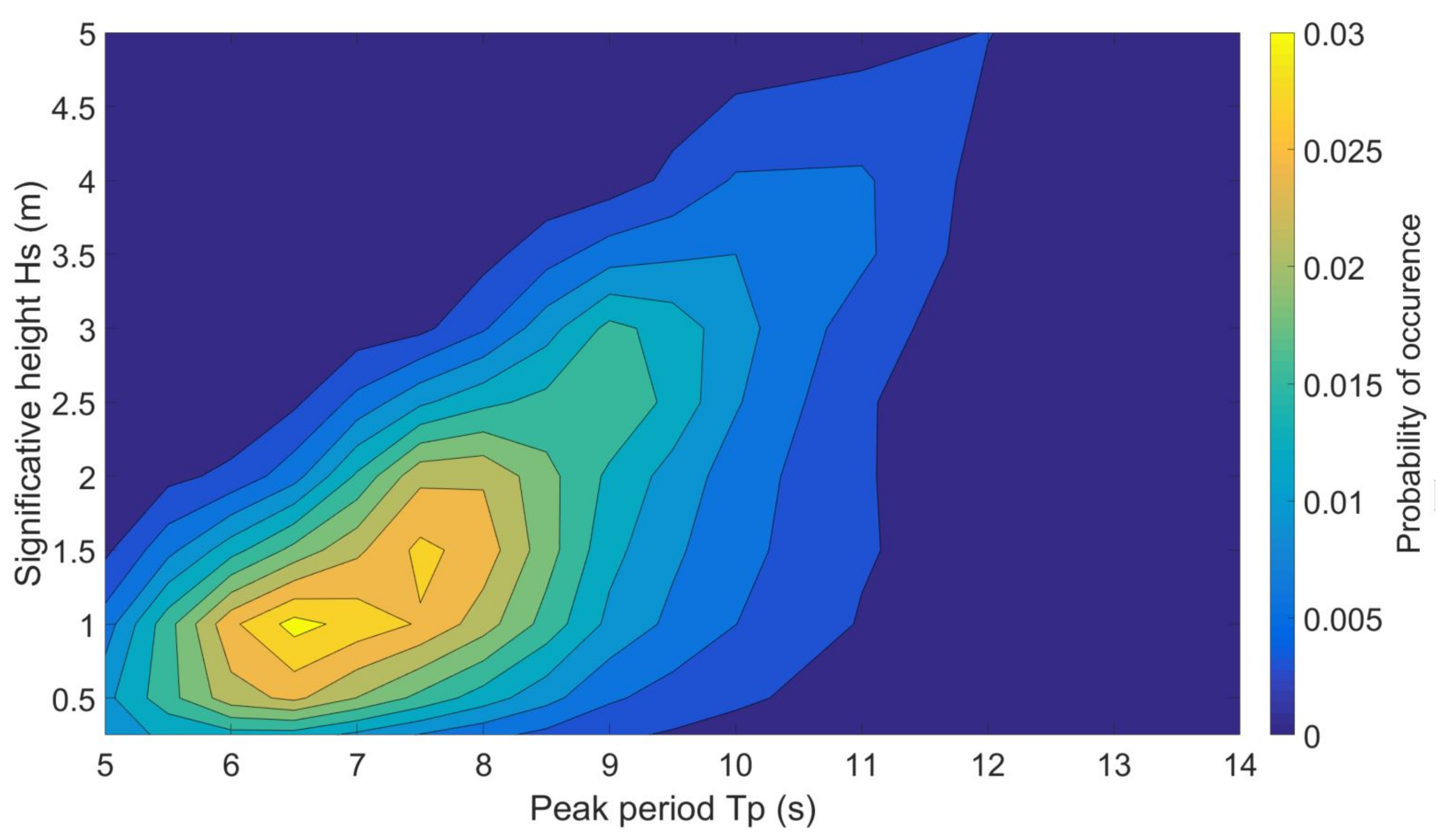
In [
15], the devices absorbed most power out of the waves for wave periods from 6 to 9 s. They are therefore well adapted for the EMEC wave energy test site located off the coast of Scotland where such wave periods prevail. The scatter diagram of the EMEC wave climate is given in
Figure 8.
For a fair comparison between the two devices, the turbines were optimised using the same methodology described below. The method described has no pretension of the being the best optimisation method. The turbine parameters to optimise are the diameter and the rotational speed. Their optimisation aims at maximising the device power output in the wave climate in which they are tested.
The optimisation of the turbines to maximise electrical power production in the EMEC wave climate was made in four steps:
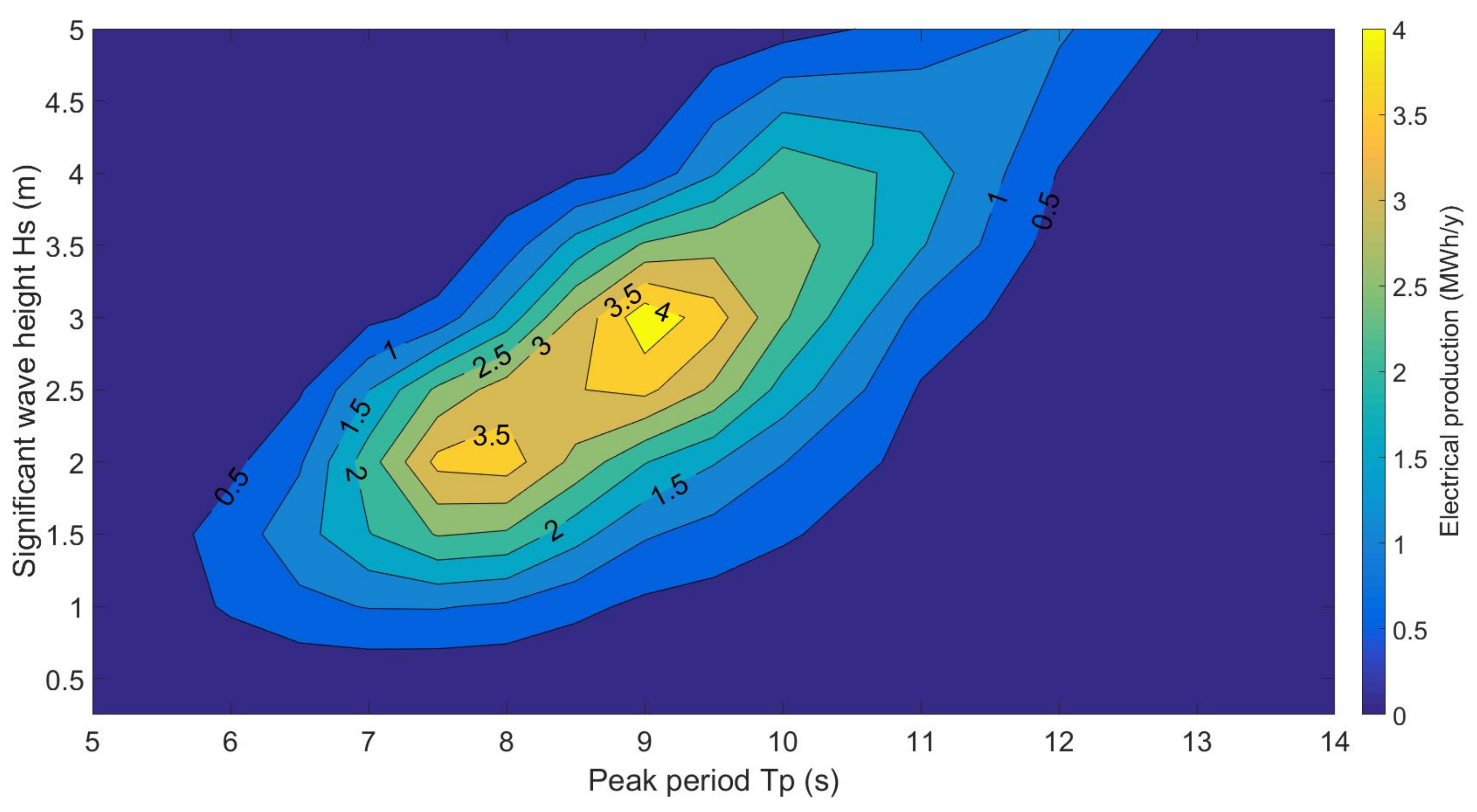
Identification of the sea states for which the devices are the most productive over the year.
Assessment of optimal damping coefficients for the most productive sea states.
Assessment of turbine diameter and rotational speed to achieve optimal damping.
Verification that the damping achieved by the chosen turbine is close to optimal.
Basic turbine models were first used. A quadratic relationship was assumed between flow rate and pressure drop across the turbine such that:
where
is the damping coefficient of the turbine. The damping of the turbine is fundamental for the efficiency an OWC device in absorbing the wave energy. As a starting point, the turbine damping coefficients obtained by parametric optimisation in [
13] carried out in regular waves were first tried over the whole EMEC wave climate and showed that the sea states of significant wave height
–
and peak period
–
are the most productive sea states over the year. Due to the large discrepancy of the sea states energy density, the most productive sea states are not the one that occur most often.
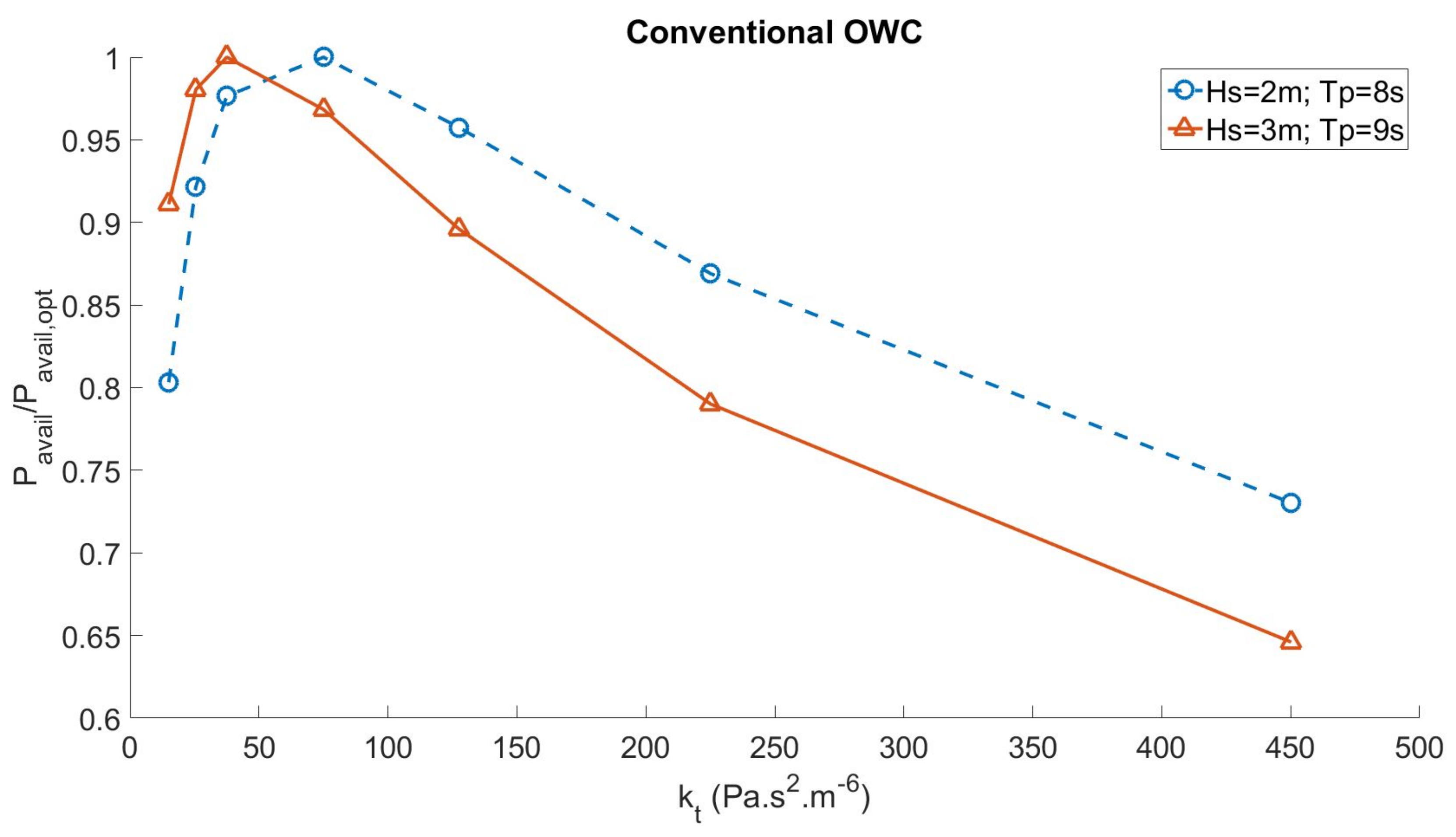
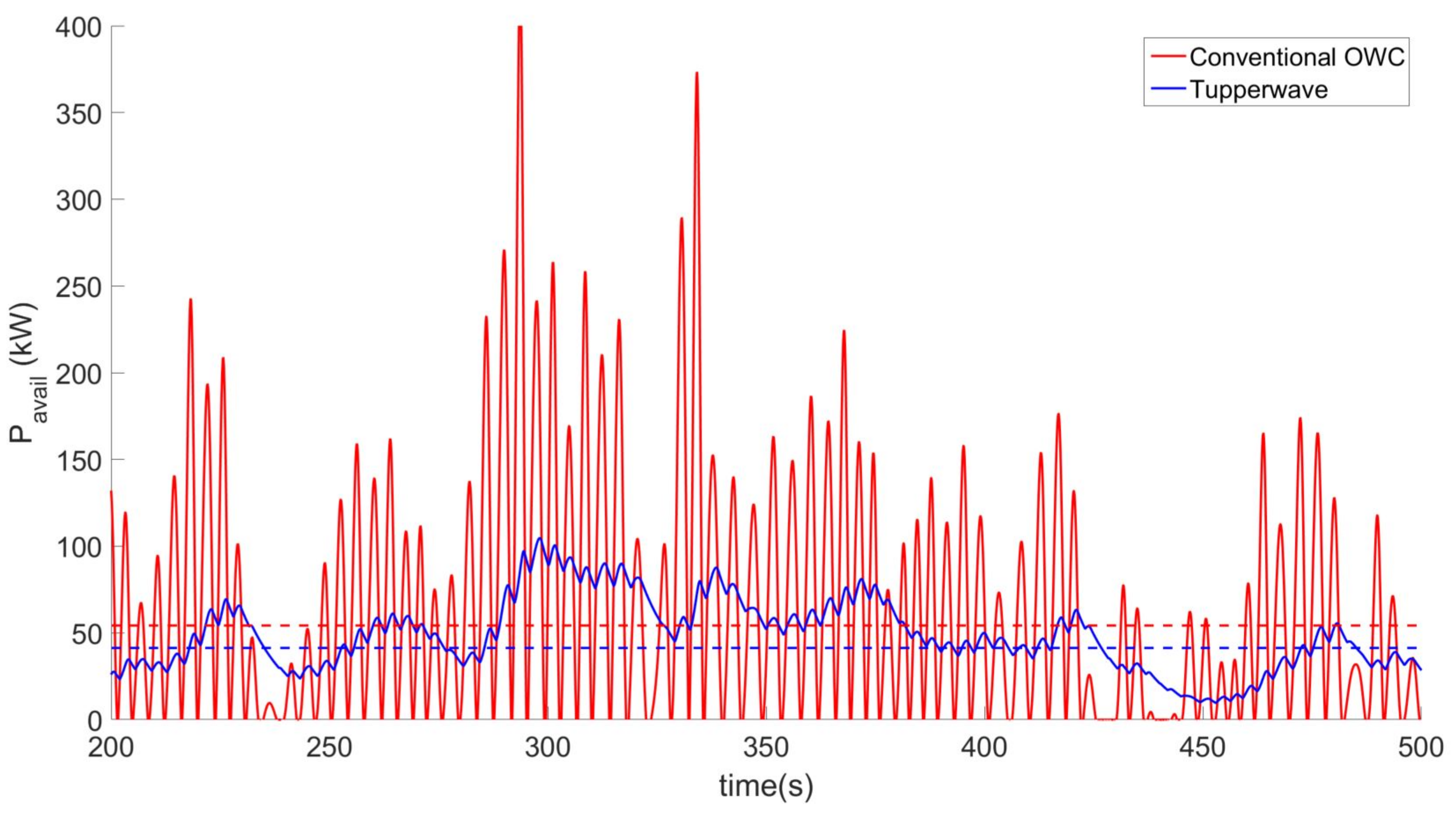
The turbine characteristics were then optimised for the most productive sea states. The damping coefficients maximising the devices’ available power in the turbine
for those sea states were investigated in detail.
Figure 9 and
Figure 10 show the evolution of the average pneumatic power flowing across the turbine
over the turbine damping coefficient in sea state
;
and (
;
) for the two devices, respectively.
It is observed that the ranges of damping coefficients maximising the power absorption from the waves are – for the conventional OWC and – for the Tupperwave device. The average flow rates achieved across the turbines in those conditions are denoted as .
It is fundamental that the turbines work close to their design flow coefficients
(highlighted in
Figure 7) which maximise their efficiencies. Therefore, for each turbine, a design rotational speed
is first chosen arbitrarily and its diameter is calculated from Equation (
8) by:
The obtained turbine characteristics are given in
Table 1.
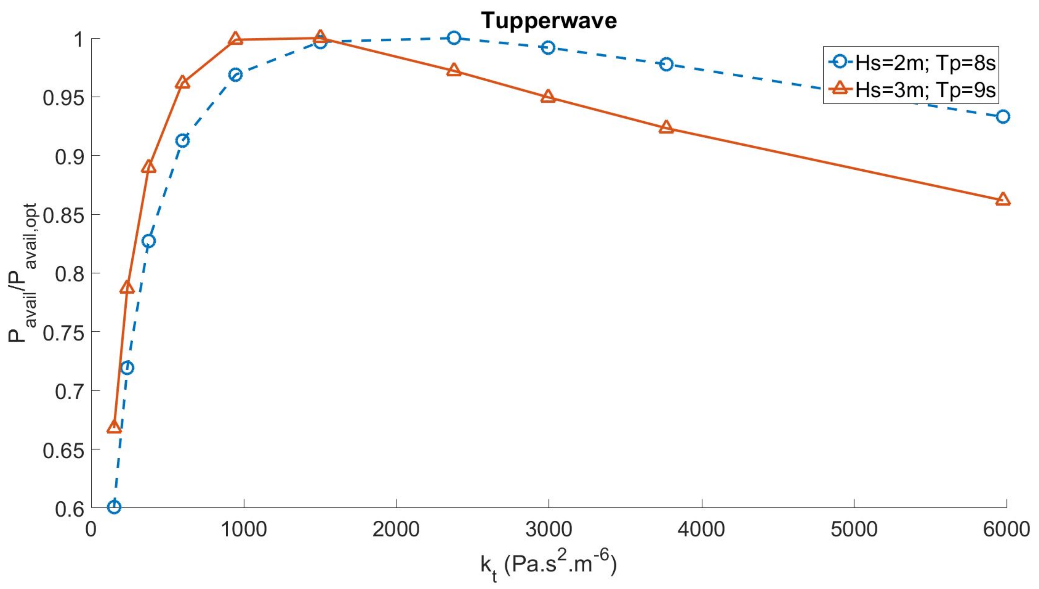
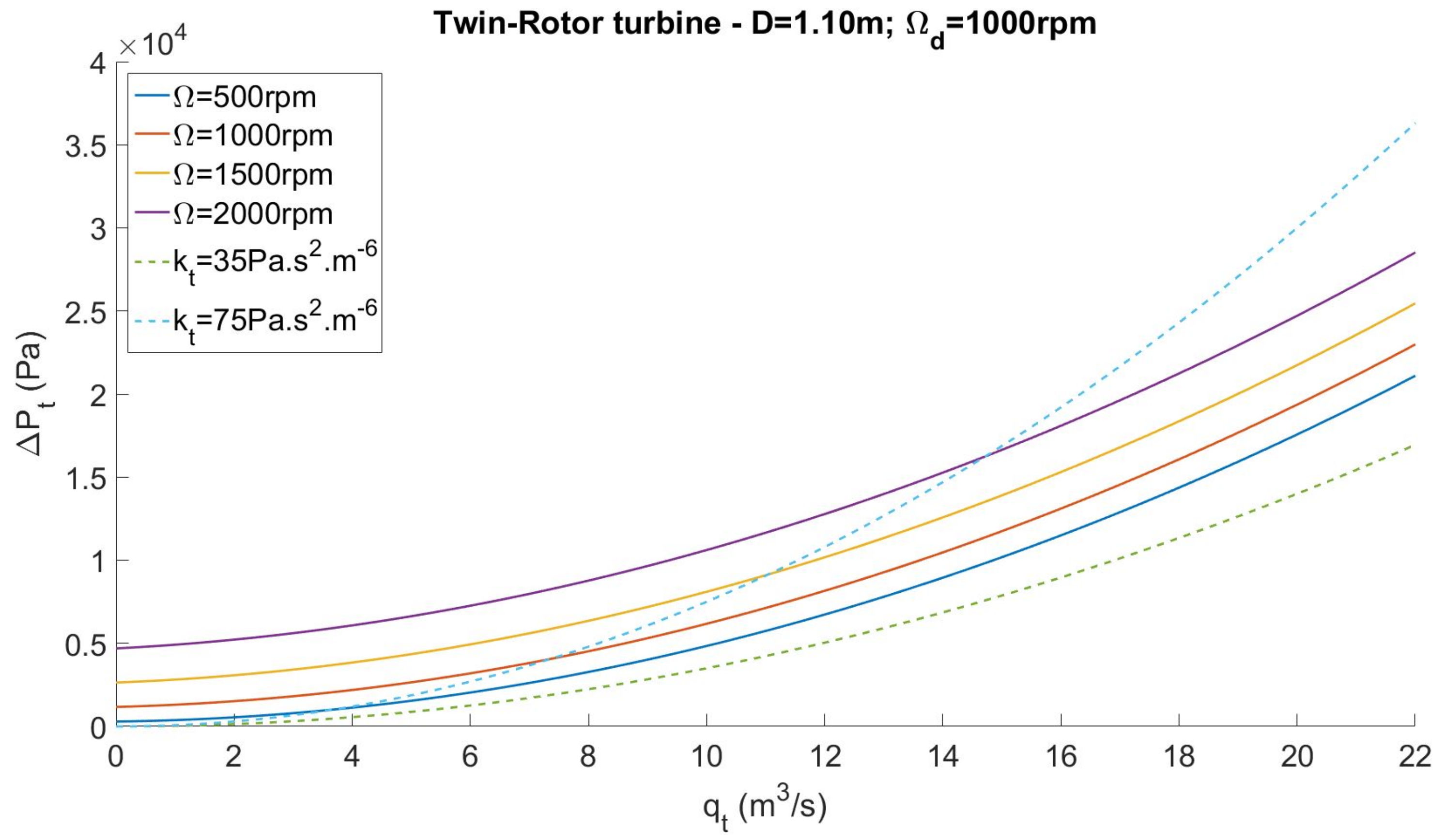
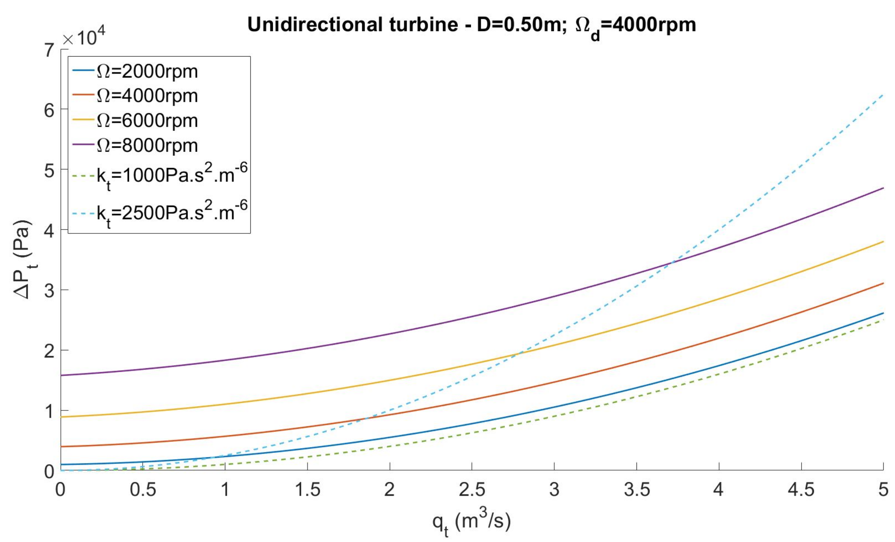
It is then necessary to verify if the diameter and rotational speed selected induce a damping close to optimal for different turbine speeds.
Figure 11 and
Figure 12 display the relationships between flow rates and pressure drops of the turbine models with the chosen parameters for different rotational speeds at which the turbines are likely to spin. They are compared with the simplified laws of optimised constant damping
. The damping achieved by the turbines for the different rotational speeds falls right in the range of optimum damping maximising wave absorption for sea states between
;
and (
;
). This confirms that the diameters and rotational speeds of the turbine are well established. If it was not the case, the rotational speed of the turbines should be reconsidered until good agreement is obtained.
It is observed in
Figure 11 and
Figure 12 that the damping of the turbines increases slightly with the rotational speed. It is, however, interesting to note that, according to
Figure 9 and
Figure 10, the optimal turbine damping becomes smaller for larger sea states where the turbine is likely to be spun faster. This shows that speed control of the turbines depending on the wave condition would theoretically enable the turbine damping to be matched with the optimal damping and hence maximise the absorbed power and the real delivered power production. In the case of the conventional OWC, the flow across the turbine very quickly varies and stops every 3–5 s to change direction. In this flow condition, a fixed-speed generator would experience severe shock loads on the generator shaft, whereas if the speed were allowed to increase, the inertia of the system would absorb some of the extra power input. This consideration led to the adoption of the more simple variable speed control law described in
Section 2.5. With such a control law, the turbines gain to be designed so that their damping stays relatively constant with various rotational speeds.
The adaptation of the unidirectional turbine tested in [
6] for the pneumatic damping needs of the Tupperwave turbine and the conventional OWC led to very different results on what concerns the size (diameter D) and the rotational speed. This is due to the different working conditions of the turbines in the two devices. The turbine in the Tupperwave device has a small diameter of
but a very high design rotational speed of
. In addition of being less mechanically complex because of the absence of valve and of a single rotor, the chosen Tupperwave turbine is half the size of the conventional OWC turbine, it is therefore likely to be much cheaper. Unfortunately, a gearbox is necessary to bring down its high design speed to a commonly used generator design speed (
) and the investment cost and maintenance issues associated with a gearbox are undesirable.
The Cordier diagram, see [
28], is an empirical diagram commonly used as a tool by turbine designers. It indicates that if the optimum operating conditions are kept constant and if the design speed of the turbine is lowered, then the diameter of the turbine increases. This shows that the use of a gearbox could be avoided if a different turbine design with larger diameter was adopted. The Cordier diagram does not, however, provide any information on the blade shape (i.e., angles and blade width) and such designing exercise is out of the scope of the present research.


