Abstract
The Wankel engine is a rotary type of four-stroke cycle internal combustion engine. The higher specific power output is one of its strong advantages. In Wankel rotary engine, every eccentric shaft revolution corresponds to one four-stroke cycle, whereas conventional reciprocating engine fulfills four-stroke cycle in two crankshaft revolutions. This means the power stroke frequency is twice that of conventional engines. Theoretically, application of two-stroke cycle on Wankel geometry will duplicate the power stroke frequency. In this research, a single-zone thermodynamic model is developed for studying the performance characteristic of a two-stroke Wankel engine. Two different port timings were adapted from the literature. The results revealed that late opening and early closing port geometry (small opening area) with high supercharging pressure has higher performance at low speed range. However, as the rotor speed increases, the open period of the port area becomes insufficient for the gas exchange, which reduces power performance. Early opening and late closing port geometry (large opening area) with supercharging is more suitable in higher speed range. Port timing and area, charging pressure, and speed are the main factors that characterize output performance. These preliminary results show a potential for increasing power density by applying two-stroke cycle of the Wankel engine.
1. Introduction
Internal combustion reciprocating engines are widely applied power sources in industry and transportation. There are many rotary mechanisms that are proposed as internal combustion engine [1]. The interest in these engines arises from their simple rotary motion without reciprocating parts. However, most of them fail in long term applications because of sealing and principal working cycle problems [2,3].
The Wankel engine is also a type of internal combustion engine, and among other rotary types, it is the only one in production. Since the 1950s, beginning with the NSU, besides some companies [2,3], many institutions and researchers have paid attention to the research and development of Wankel engine [4,5]. It is clear that Mazda Corporation is the leading company for the latest developments in the automotive industry [6,7,8]. The main advantages of the Wankel-type rotary engine are higher specific power output and reduced vibration. On the other side, the main disadvantages are higher fuel consumption and shorter lifetime compared with conventional reciprocating engines.
Over more than 50 years, many disadvantages of the Wankel engine have been eliminated or improved. There are vast literature sources related to this development effort, concentrated on combustion chamber geometry [9,10], direct injection and stratified charge [11,12], port geometry [13,14], and sealing [15], etc. The Wankel engine has the potential to be applied in areas where lightweight, low vibration, and use of some alternative fuels (H2, NG etc.) are required [16,17,18]. The primary advantage of the Wankel engine is its high specific power output. This advantage enables the Wankel engine still to be used in some small vehicles, unmanned air vehicles, and lightweight industrial equipment. It is clear that, if the power density of the Wankel engine may be increased by applying the two-stroke cycle, the potential usage of this engine as a power source will expand such as in range extenders and unmanned air vehicles, where the power/weight ratio is an important parameter.
In the early stage of the Wankel’s development, the idea of two-stroke application on this geometry was also proposed. This can be seen from some patent applications. In the first patent, scavenging was described with conventional valves on side walls [19]. The second patent describes ports on side walls, which are controlled by rotor flank [20] and the third patent describes an additional compressor adapted on scavenging channels [21]. To the best of the authors’ knowledge, there is no additional study available in the literature except these patents.
Internal combustion engine modelling is an economical tool for predicting the effect of design innovations before their experimental development. There are various types of models and they have different accuracies depending on the objective being analyzed. Thermodynamic models are mainly divided into two types, which are single-zone and multi-zone.
In single-zone models, the only independent variable is time, and the combustion chamber is assumed as a control volume with homogeneous thermodynamic properties. These models incorporate empirical laws and coefficients for combustion through the mass burning rate, heat transfer, charge exchange, etc. The geometry of the combustion chamber and flame front do not play an explicit role in the evolution of the engine variables. This type of model is computationally easy to apply and allow us to obtain accurate results for effective performance parameters depending on the selection of appropriate empirical laws and coefficients.
In multi-zone models, the combustion chamber is divided into several zones. These types of models permit one to analyze the effects of temperature and mixture stratification, which leads to a better estimation of combustion duration and exhaust emissions (especially NOx).
Fluid dynamic models (CFD) are multi-dimensional models, which are based on the conservation of mass, chemical species, momentum, and energy at any location within the engine combustion chamber. Both time and spatial coordinates are independent variables. This type of model additionally permits one to analyze the effects of flow conditions and combustion chamber geometry. On the other hand, CFD models are more complex, require computer hardware, computation time is much higher, and the accuracy of the solution is dependent on the fineness of the grids.
The objective of this work is to find out the constrains and the potential of increasing the power density by applying the two-stroke cycle on the Wankel engine and to produce basic knowledge for further research steps.
In this research, a single-zone thermodynamic model is developed for studying the performance characteristics of a two-stroke gasoline Wankel engine [22,23]. The thermodynamic model results will decrease the necessary time and effort for the CFD model and experimental studies [24,25]. According to the absence of academic research on the two-stroke Wankel engine, model parameters are taken from the four-stroke Wankel and two-stroke cross scavenging reciprocating engines and adapted to the new geometry. The geometry of the model is chosen from the widely applied Mazda 13B engine. Timings for scavenging and exhaust ports are taken from the usual cross-scavenging two-stroke reciprocating engines [26]. This study is the first attempt to model and define the basic parameters and constrains of the two-stroke Wankel engine concept. The aim of this work is to find out the potential of increasing the power density and to analyze the feasibility of a two-stroke Wankel engine as a preliminary design tool to determine the effect of basic port configurations and performance characteristics.
2. Theoretical Background
Essentially, the Wankel engine operates with the four-stroke cycle principal. As seen from Figure 1, the reciprocating engine fulfills the four-stroke cycle in two crankshaft revolutions (720 °CA-Crank Angle). However, the Wankel engine’s eccentric (main) shaft completes three revolutions at each rotor revolution (1080 °EA-Eccentric Angle). At each rotor revolution, every side of the rotor fulfills its own four-stroke cycle. Hence, each rotor revolution has three four-stroke cycles in total. This means that every eccentric shaft revolution corresponds to one four-stroke cycle.
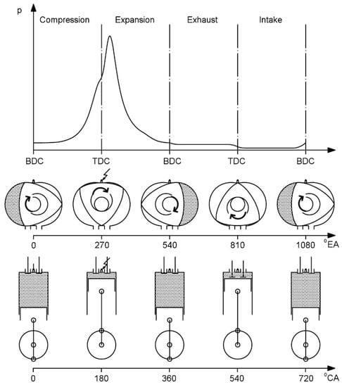
Figure 1.
Four-stroke cycle for reciprocating and Wankel engines.
By this way, Wankel engine produces power for per eccentric shaft revolution, which is the basis of its high specific power output. In order to distinguish the rotary engines from reciprocating engines, considering power output, the related equations are given below. The indicated power per cylinder (combustion chamber) is:
where Wi is the net indicated work per cycle in one cylinder (combustion chamber):
where IMEP is net indicated mean effective pressure (specific work) and Vh is stroke volume of one combustion chamber. The power stroke frequency is defined by:
where ne is main shaft rotational speed and kf is the work stroke fraction [27].
Table 1 shows kf factor for different engine types and cycles.

Table 1.
Work stroke fractions for different engine types and cycles.
Thus, Equation (1) for indicated power per cylinder with the above given variables takes the form:
The power of the engine for a given stroke volume, speed, and indicated mean effective pressure depends on work stroke fraction. For constant speed and power (constant load), Equation (5) can be rewritten as follows:
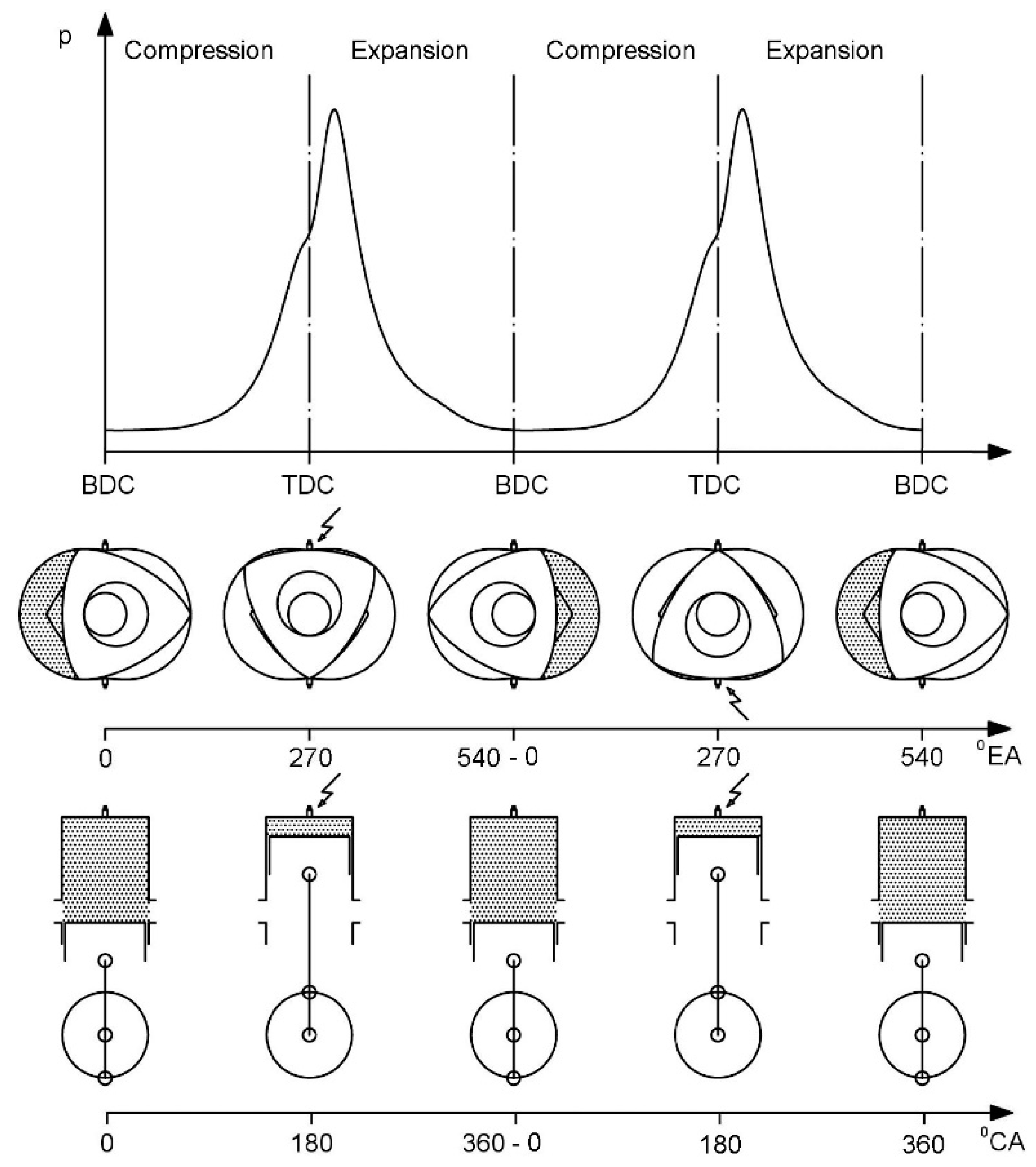
The right-hand side of Equation (6) describes the IMEP per stroke and may be defined as “Indicated Mean Work per Stroke-IMWS”. This definition gives an opportunity to compare the specific work for different type engine and cycles. From these equations, it is seen that two-stroke Wankel engine increases the specific power a further step. According to the two-stroke Wankel engine geometry, which is proposed in this work, there are two windows facing each other from both sides of the housing where the scavenging occurs. Figure 2 shows two cycles of two-stroke for Wankel and reciprocating engines.

Figure 2.
Two-stroke cycle for reciprocating and Wankel engines.
Figure 2 shows that the conventional engine completes two-stroke cycles in one crank shaft revolution (360 °CA). In the two-stroke Wankel rotary engine, at each rotor revolution, every three sides of the rotor complete two total cycles (two stroke), i.e., two two-stroke cycles per eccentric shaft revolution.
3. Geometry and Geometrical Constrains
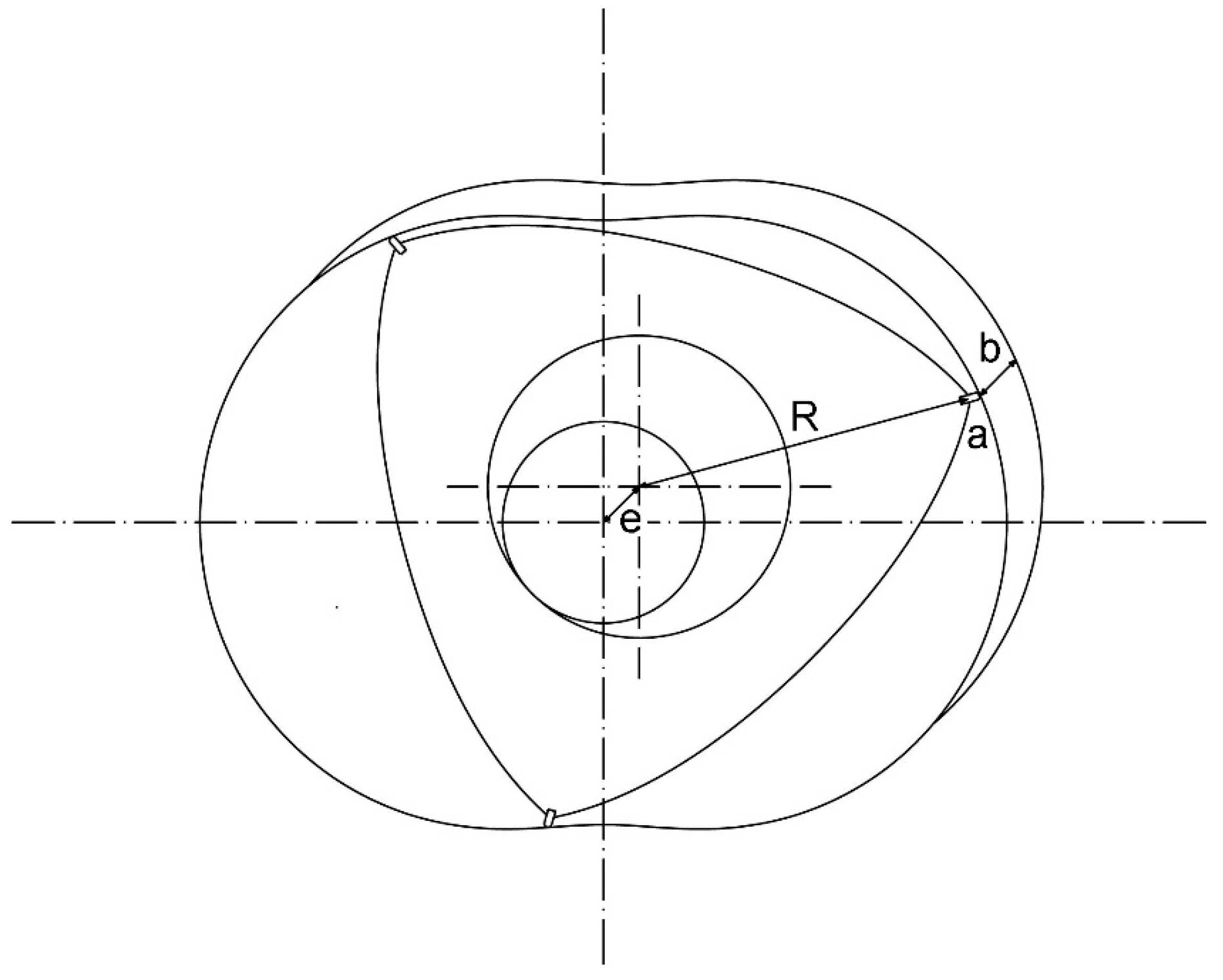
The thermodynamic cycle process has been calculated considering the geometrical data. Two of them are volume and surface area of combustion chamber according to rotor position. For the calculation of the intake and exhaust flow, scavenging and exhaust port areas are also required. As is known, Wankel engine geometry is derived from trochoidal curves [2,3,4]. There are mainly four parameters, which define the shape of the Wankel engine geometry as shown in Figure 3.

Figure 3.
Wankel engine geometry (e: Eccentricity, R: Generating radius, a: Equidistance, b: Width).
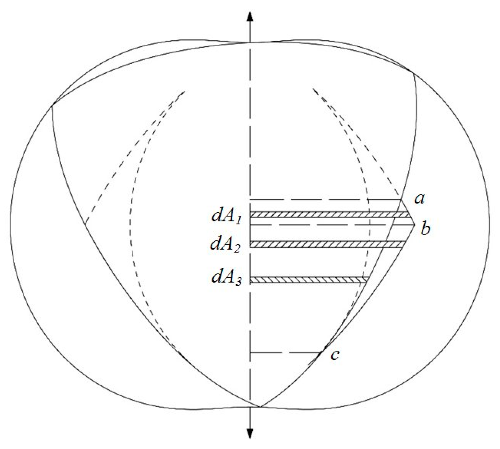
In two-stroke reciprocating engines, scavenging and exhaust ports are basically placed on side wall of the cylinder. By this way, the movement of the piston simply controls the flow in and out of the combustion chamber. With respect to top dead center, opening and closing timings of these ports are symmetrical during the cycle of its geometrical nature. The areas of these ports are functions of opening–closing time and their height. Similar to conventional reciprocating two-stroke engine, piston (rotor) flank edge-controlled ports on side wall of rotary engine are used in this study. Curves that form port geometries are derived from the rotor flank geometry. The open part of the port is calculated by difference of integrated areas (Equation (7)), shown in Figure 4 as shaded.
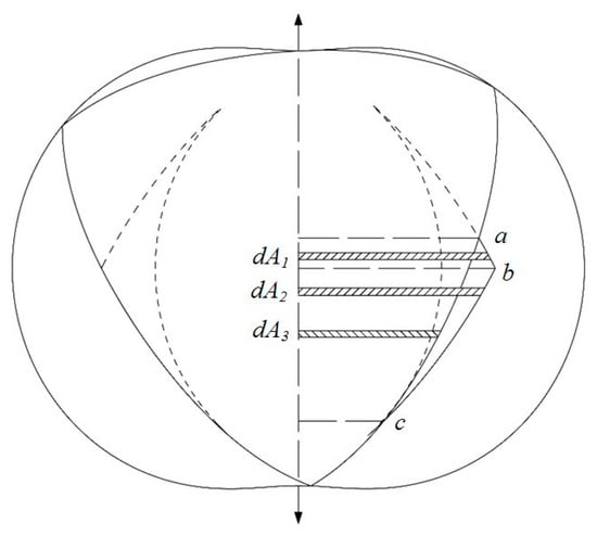
Figure 4.
Two-stroke Wankel engine port areas.
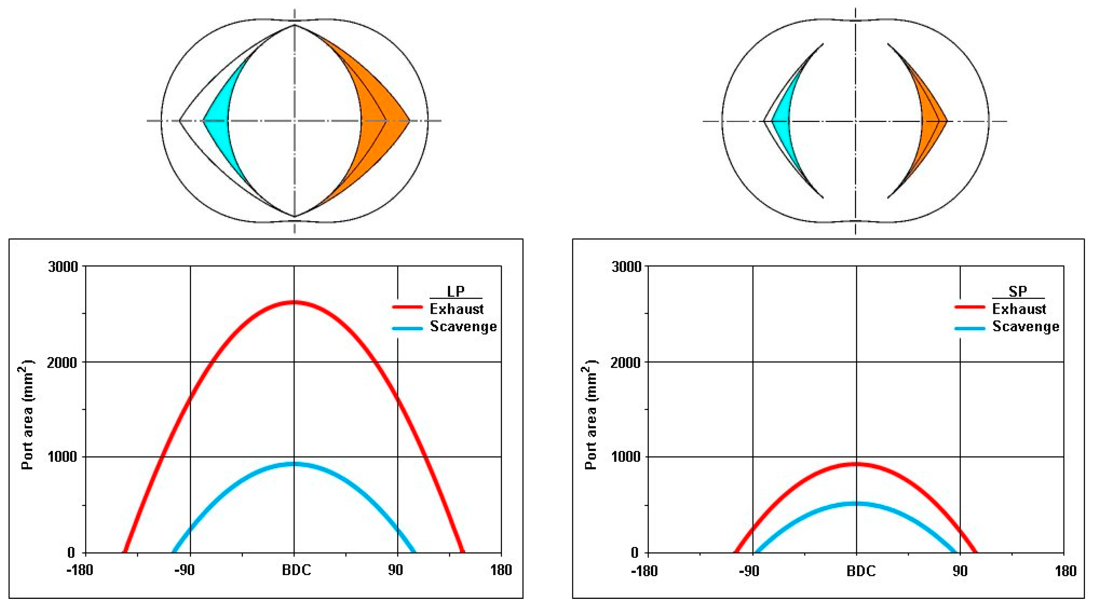
Port timings of charge and discharge of the gasses have a key role for the performance of two-stroke engines. Two types of typical port timings for a two-stroke engine controlled by piston movement are selected from Blair [26] and given in Table 2. These types of port timing events are symmetrical, which means the closing times of exhaust and scavenge ports are identical to their opening times (Figure 5). Since two-stroke of reciprocating engine equals 360° crank angle and the equivalent of this for a Wankel engine is 540° eccentric shaft angle, the values of timings from reciprocating engines are converted to Wankel geometry by multiplying 3/2, as shown in Table 2. Due to the Wankel geometry, these timings also define the surface area of ports, where this is a function of arc length of ports at cylinder surface in the case of reciprocating engine. Early opening and late closing ports are called “Large Ports” and abbreviated with LP. Conversely, late opening early closing ports are called “Small Ports” and abbreviated with SP (Figure 5).
Table 2.
Typical port configurations for two-stroke reciprocating engines [26] and conversion to the two-stroke Wankel engine.
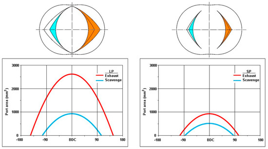
Figure 5.
Two-stroke Wankel engine configuration with large and small port (LP and SP) areas.
4. Thermodynamic Cycle Simulation
As the control volume of the thermodynamic model, just one of the combustion chambers is chosen. It is an open system, which includes gas exchange. Governing equations of the model are conservation of mass and energy, and ideal gas law.
Conservation of mass:
The conservation of mass equation for a finite time interval in our model takes the form:
(a) Mass of fresh charge (fc) and combustion products (ex) in combustion chamber after ∆t time interval.
(b) Mass of fresh charge (fc) and combustion products (ex) in combustion chamber before ∆t time interval.
(c) Accumulated mass in combustion chamber during ∆t time interval.
(d) Fuel mass ingested into the combustion chamber (increase of combustion products ṁexf and decrease of fresh charge ṁfcf due to combustion).
(e) Total incoming mass (combustion products ṁscex and fresh charge ṁscfc inflow from scavenging port and combustion products from backflow ṁexbf of exhaust port).
(f) Total outgoing mass (combustion products outflow from exhaust port ṁex and from scavenging port ṁscex).
Conservation of energy:
where d(mcec) is internal energy change in combustion chamber, dmsc hsc is enthalpy of incoming charge (scavenging), dmex hex is enthalpy of outgoing products (exhaust), pcdVc is work done, and dQc heat addition or loss in combustion chamber.
Ideal gas law:
By differentiating of energy and ideal gas equations with respect to time, the pressure change in the combustion chamber can be written as follows.
Converting time to eccentric angle:
The first two terms of the right-hand side of Equation (12) represent the gas exchange process, which is calculated using one dimensional compressible isentropic flow rate:
where flow function is calculated by the following relation:
During the gas exchange process, it is assumed that the flow does not exceed sonic speed. For this assumption, a critical pressure ratio control is included as follows:
When the critical pressure is achieved, or in other words flow exceeds sonic conditions, the flow at ports becomes choked.
For inclusion of irreversibility, the one-dimensional compressible isentropic flow equation is multiplied by the discharge coefficient (µsc and µex). Discharge coefficients of ports are determined from experimental results and depend on shape, flow direction (in or out), pressure ratio, and open area ratio [28]. With the assumptions that the highest-pressure ratio is obtained at minimum open area and the lowest pressure ratio is obtained at full (maximum) open area, a linear regression approximation depending on open area ratios from the experimental data in the literature can be made [28,29].
In two-stroke engines, there is a period defined as scavenging period during which inlet and exhaust ports are open. In this study, filling and emptying method with simultaneous charging and discharging (scavenging process) is applied [30]. Fresh air and exhaust gases are mixed during the scavenging process in the combustion chamber. Pressure, temperature, and specific heat of the mixture are calculated as mean values for the complete combustion chamber. The boundary conditions are taken constant, which are temperature and pressure, at inlet and exhaust ports. The unsteady flow in pipes is simplified by assuming short pipe lengths for both inlet and exhaust parts, i.e., the flow is accepted as quasi-steady [30].
The backflow from the exhaust to the combustion chamber or from the combustion chamber to the inlet is detected with the pressure difference. The backflow gas from the exhaust channel has the same temperature as in the control volume. The same assumption is valid for the backflow from the control volume to the inlet channel. Additionally, it is assumed that the backflow gas (from combustion chamber to the inlet ports) does not mix with the fresh charge; hence, with the change of the flow direction, first backflow gases re-enter into the combustion chamber, and then fresh charge enters.
Definitions of thermodynamic terms used in connection with two-stroke engine are as follows [26]:
- mas: Total fresh charge supplied from scavenging port;
- msref: Reference charge mass at scavenging conditions that fills the total combustion chamber (swept volume + compression volume);
- mtas: Total trapped fresh charge;
- mtr: Actual charge in combustion chamber (Fresh charge + Combustion products).
- Scavenging Ratio
- Scavenging Efficiency
- Trapping Efficiency
- Charging Efficiency
4.1. Heat Transfer
The instantaneous rate of heat transfer from the combustion chamber is:
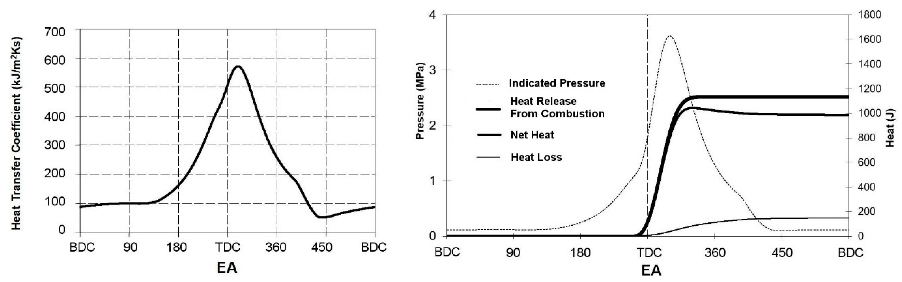
In this equation, wall temperature (rotor, side, and housing) is taken as constant (Twall = 453 K). Surface area is calculated from the geometry of the engine for each rotor position. Combustion chamber temperature and heat transfer coefficient are calculated for each step of the cycle. The instantaneous heat transfer coefficient for internal combustion engines are usually calculated with semi-empirical similarity rules. Woschni’s equation is widely used for conventional reciprocating engines [31]. Wilmers has adapted an equation from Woschni for Wankel geometry [32]. The same equation is used in this model while the dimension of the NSU KKM 502 engine of Wilmers’s work is similar to the Mazda 13B engine. Figure 6 shows the change of heat transfer coefficient in the combustion chamber.
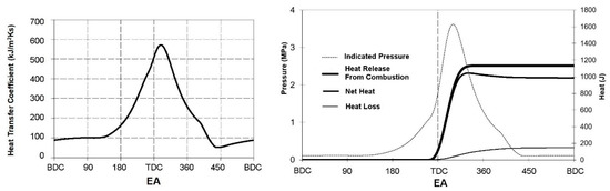
Figure 6.
Heat transfer coefficient and cumulative heat release (LP—1.5 bar—4000 rpm).
4.2. Combustion
Fuel quantity (gasoline) in the combustion chamber is calculated according to the amount of fresh charge. Model calculations are made for stoichiometric mixture. Combustion process, i.e., heat release, is calculated according to the Vibe function and applied as a single-zone model [33]. Combustion efficiency is assumed to be 95% for whole working conditions; hence, heat release is also calculated with this assumption. Figure 6 shows an example of heat transfer coefficient, heat release, and loss in the combustion chamber.
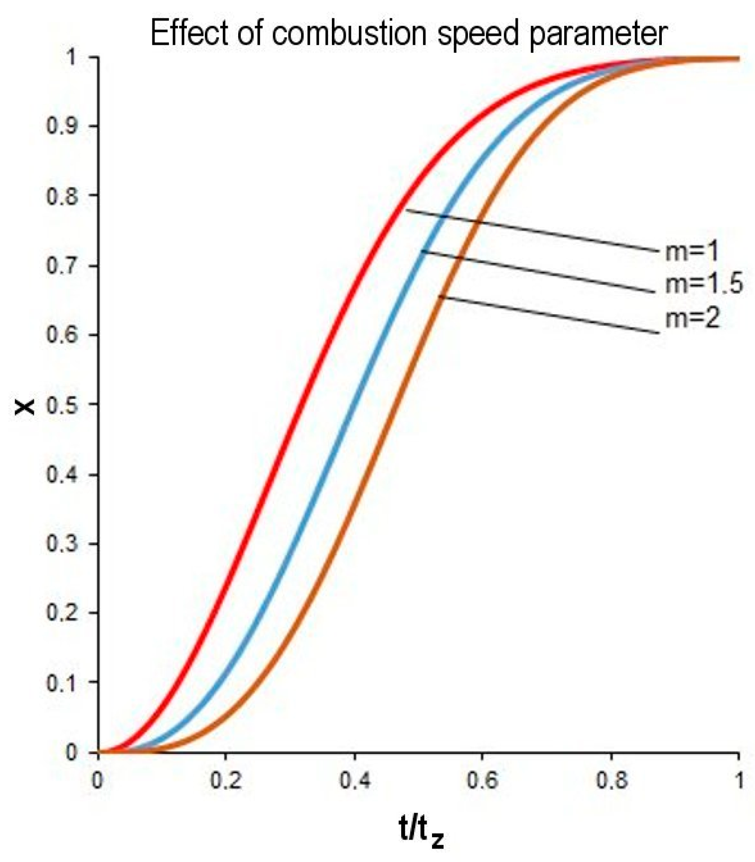
The exponent m in the Vibe function, which specifies combustion rate vs. time is taken variable according to the engine speed (m = 1.5 for 2000 rpm, m = 1.75 for 4000 rpm, m = 2.0 for 6000 rpm) and combustion duration in EA for all engine speeds is set as constant (tz = 100°EA) [34,35,36]. These results are supported by the experimental data of Tsao and Losinger [36] at full load conditions (Figure 7).

Figure 7.
Effect of combustion speed parameter on heat release shape of Wankel engine for different engine speeds.
For the whole process, the mean specific heat is calculated as follows:
The specific heat of the fresh charge is taken as linear and combustion products are taken as second-order functions of the temperature [37].
4.3. Instantaneous Conditions in Combustion Chamber with Forward Marching
After calculating the mass balance from Equation (9) and pressure difference from Equation (12) with a given time step, new pressure and temperature can be calculated from the following equations.
For precise calculation, the numerical differential time steps must be chosen as small as possible. Additionally, a correction step in the interval of the time must be used. In this study, the correction step is applied according to modified Euler (Heun) method [38] as follows:
First step:
Correction Step:
Second Step:
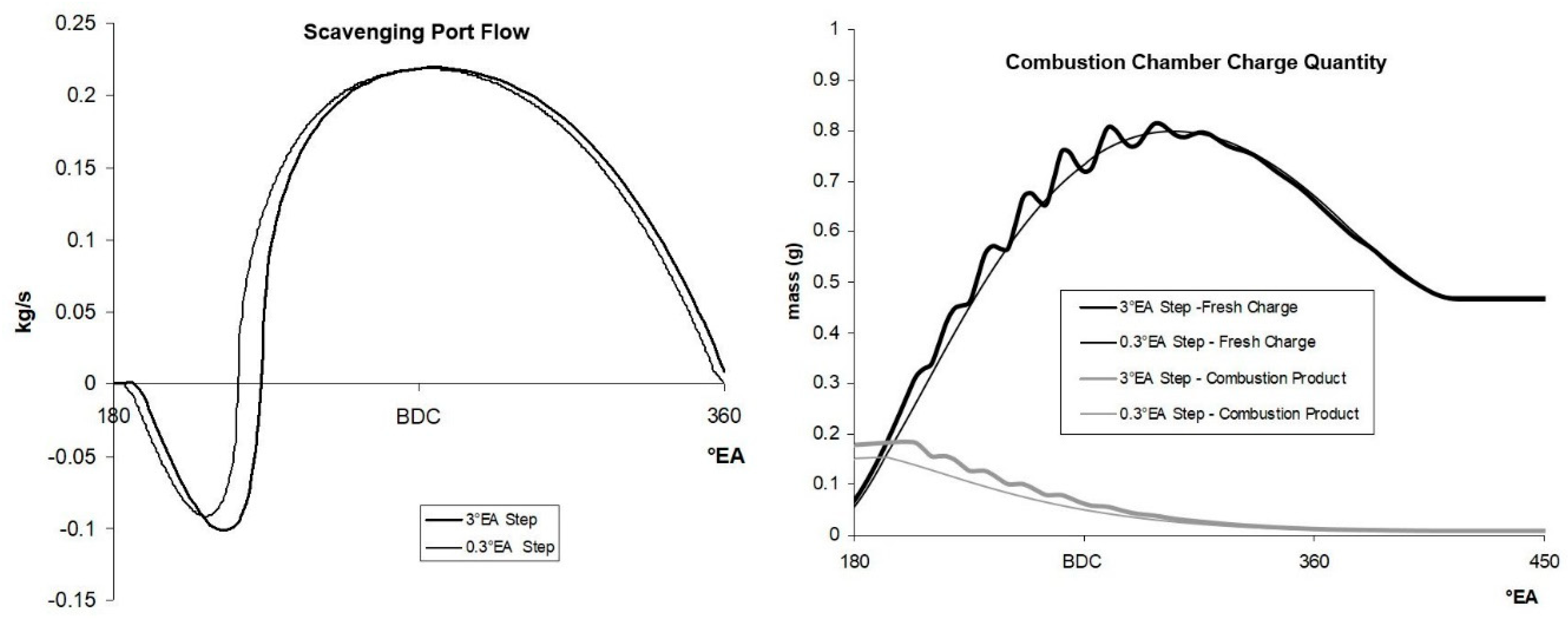
The time step is defined according to the rotor angle (1°RA, 0.1°RA), which rotates with one-third of the speed of the eccentric shaft (3°EA, 0.3°EA). Results of two different time steps for charge exchange are shown in Figure 8. Results of the large time step produce numerical fluctuations on charge and combustion product quantities, as seen in Figure 8. For this reason, 0.1°RA (0.3°EA) step size is chosen for the further calculations.
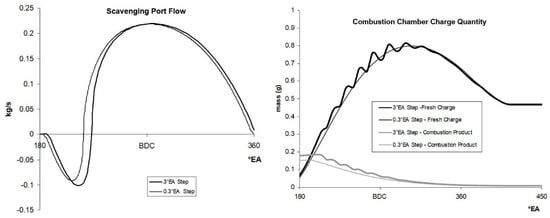
Figure 8.
Effect of time step on scavenging port flow and combustion chamber charge quantity (2.5 bar charge pressure, 4000 rpm).
4.4. Frictional Loss and Effective Parameters
In reciprocating or rotary engines, frictional loss has a decreasing effect on power output. For determining the effective parameters friction loses must be included in the calculations. Frictional losses may be defined as the mean frictional pressure (FMEP).
where IMEP is indicated mean effective pressure and BMEP is brake mean effective pressure.
Mean frictional pressure (FMEP) in conventional engine depends strongly on engine speed and weakly on engine load (BMEP). According to experimental results in the literature, mean frictional pressure increases linearly with engine speed and load [39]. In the case of Wankel engine, mean frictional pressure varies with the second-order functions of the engine speed. Additionally, it depends more strongly on engine load compared to the conventional engine [39]. Basshuysen’s test engine was Audi NSU KKM871 and it is slightly larger than our model engine (Mazda 13B). In the presented work, a multiple regression with a second-order term of engine speed and first-order term of engine load is derived from the given data of mentioned work.
5. Thermodynamic Model Results
In Table 3, the main geometry and working conditions of the model engine are summarized. There are two different types of port geometries (large port—LP; small port—SP) [26], three different charging pressures (1.2 bar, 1.5 bar, and 2.5 bar), and three speeds (2000, 4000, and 6000), hence 18 conditions are calculated. Combustion parameters (rate and duration) are taken from experimental data in the previous four-stroke Wankel engine literature [34,35,36].
Table 3.
The geometric and working condition parameters used in thermodynamic model.
In two-stroke engine terminology, the compression ratio is defined as the trapped compression ratio referring the volume after exhaust port closing. In order to avoid confusion, in this study, geometric compression ratio (εgeometric) is used by adhering to the four-stroke terminology.
5.1. Indicated and Effective Parameters
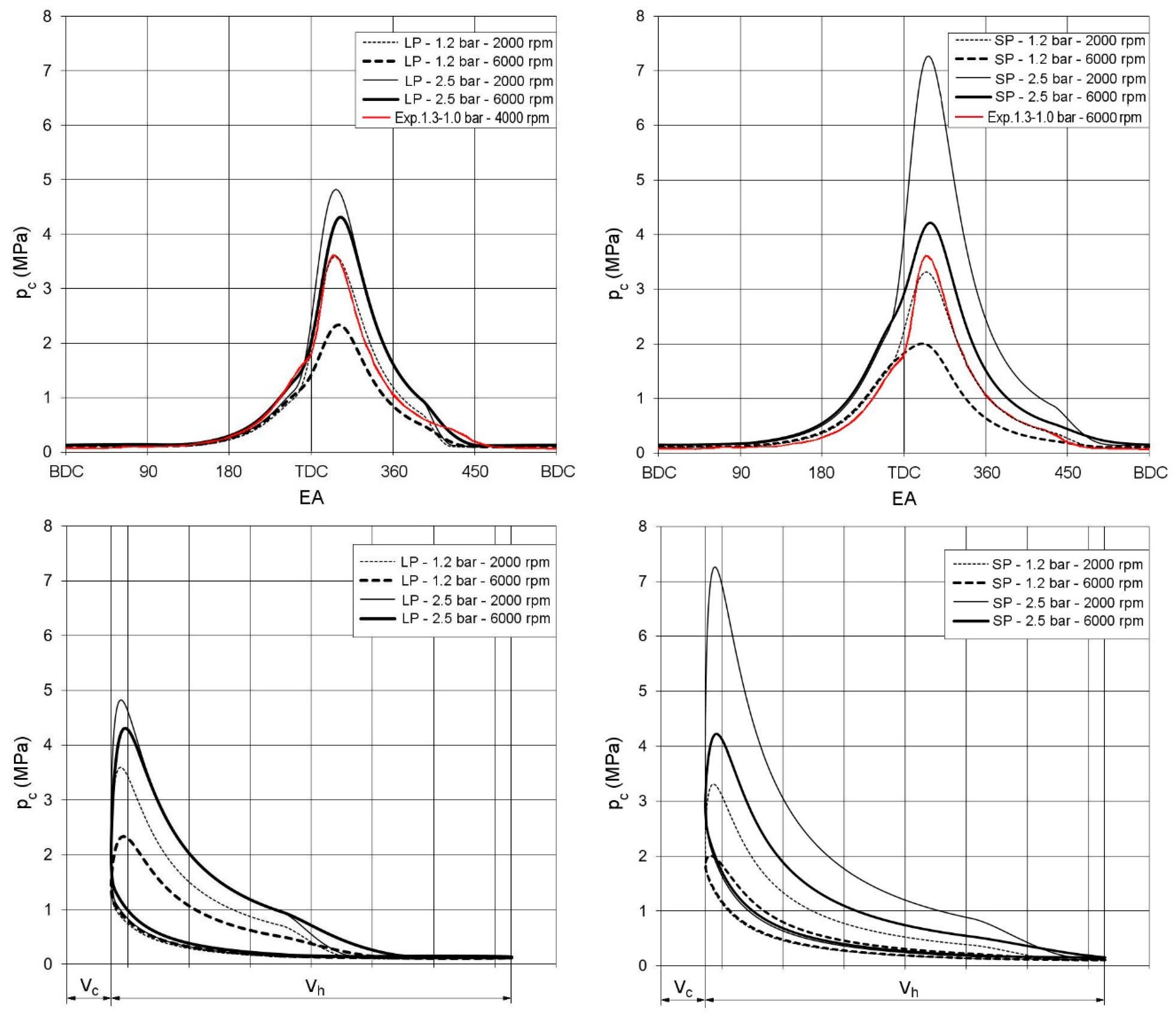
Indicated parameters from p-V diagram by volume step integration are calculated and shown together with p-EA diagram in Figure 9. For comparison and validation of model calculations, a small-size two-stroke conventional SI engine’s experimental data are used [40]. Mentioned conventional engine is crankcase scavenged and scavenging pressure during intake is approximately between 1.3–1.0 bar. In Figure 9, the left and right sides show the results of LP and SP configurations, respectively. Experimental p-V data of conventional two-stroke reciprocating engine at 4000 and 6000 rpm are plotted on the left and right graphs. Experimental data are in good agreement with 1.2 bar scavenging pressure and 2000 rpm working conditions of two-stroke Wankel engine model results (especially with LP configuration). At higher speeds, for the two-stroke Wankel engine, the combustion pressure is significantly lower. The reason for this is the restricted port cross section areas of the two-stroke Wankel geometry, which was explained in Section 3, Table 2, and Figure 5.
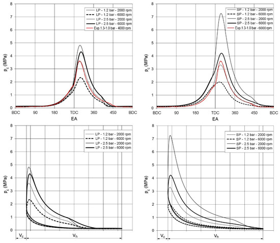
Figure 9.
Indicated pressures for LP and SP configurations at various charging pressure and speeds.
Maximum pressure points are approximately between 20–30°EA ATDC and the values are between 2.00–7.27 MPa. It is seen that for both LP and SP, increasing charging pressure and decreasing speed lead to higher pressure levels, which generate higher indicated work. At 2000 rpm and 2.5 bar charging pressure, SP configuration has a much higher peak pressure in comparison to LP configuration. This leads to higher work production together with longer expansion ratio before exhaust port opening in SP configuration. The reason for this difference is due to the higher geometric compression ratio and more effective supercharging at given conditions. On the other hand, this advantage of SP configuration diminishes at the same charging pressure with increasing the engine speed (6000 rpm). The reason for this situation can be explained as a very short time for charge exchange duration and insufficient port areas. With lower charging pressure at scavenge (1.2 bar), the peak pressures for both configurations decrease. The reason is lower fresh charge amount trapped in the combustion chamber compared to higher scavenging pressure. Another observation is that, at lower charging pressure in SP configuration, the port areas are insufficient for filling the combustion chamber. This can be seen from the compression line and lower peak pressure of SP in comparison to LP (Figure 9).
Maximum pressure (pmax), exhaust port opening pressure (pex), indicated (pmi), effective (pme), and frictional (pmf) mean effective pressures of LP and SP geometry at 1.2–2.5 bar charging pressures and for 2000-6000 rpm engine speeds are shown in Table 4. The applied charging pressures (2.5 and 1.2 bar) ratio is approximately 2.08, while the maximum pressure ratios for LP and SP are approximately between 1.3–1.8 and 2.1–2.3, respectively. This comparison between LP and SP shows that supercharging may be applied more effectively to small-port geometry. Especially at low speed and high charging pressure conditions, SP configuration is more dominant. The specific indicated work with SP configuration at 2000 rpm and 2.5 bar charging pressure is 64% higher than LP application. This advantage for SP application diminishes at higher speeds and lower charging pressure. The best indicated mean effective pressures at four different working conditions are marked in Table 4.
Table 4.
Indicated, effective, and frictional parameters for LP and SP configuration at four different conditions (best points of indicated mean effective pressure are marked cells).
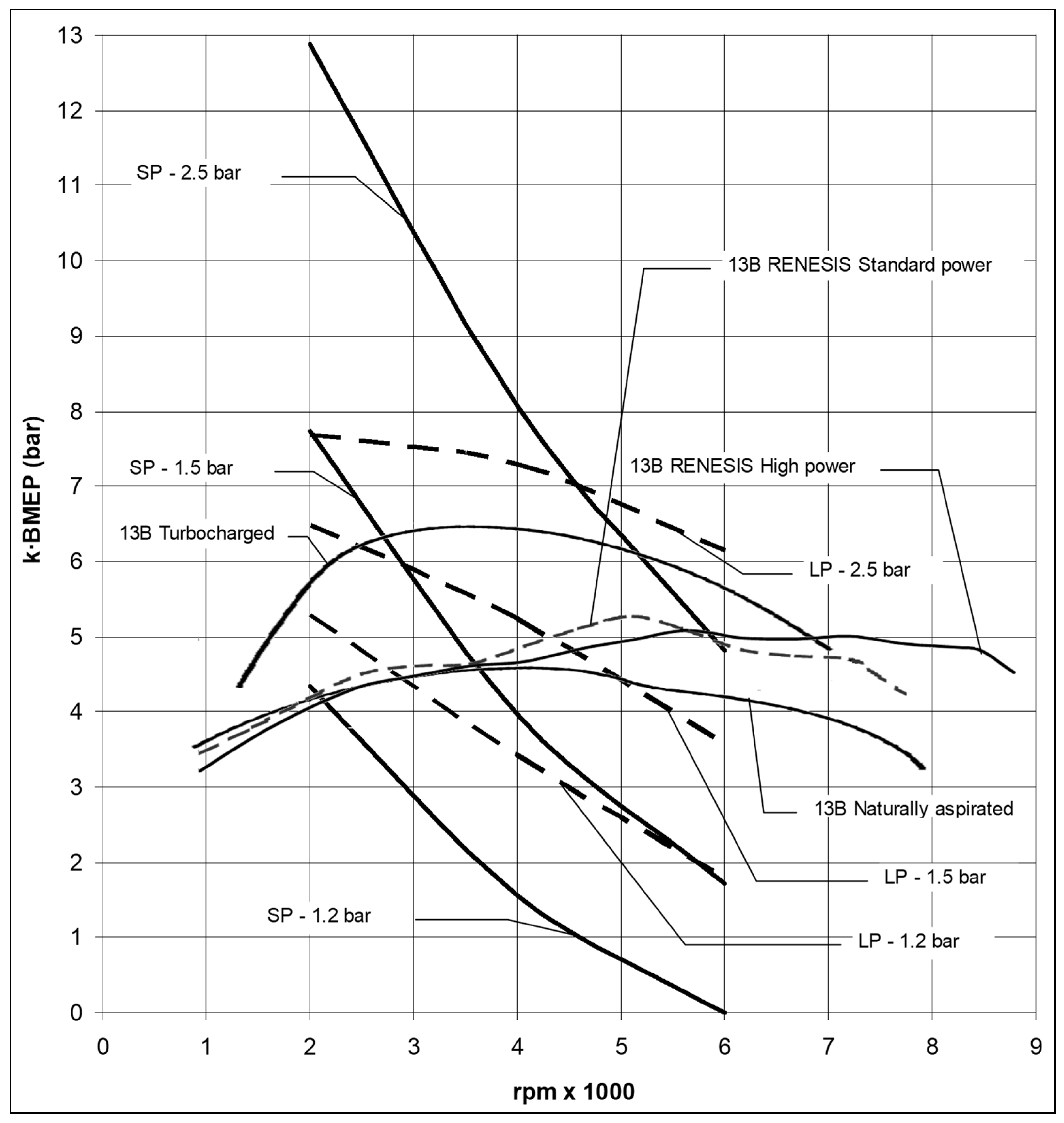
The effective power of the engine for a given stroke volume, speed, and brake mean effective pressure (BMEP) depends on work stroke fraction (kf), which was mentioned in Section 2, Equations (5) and (6). For the comparison of two- and four-stroke Wankel engines, work stroke fraction multiplied with BMEP (brake mean effective work per stroke—BMWS) is calculated by using the stroke fraction parameter. Figure 10 shows the mean effective work per stroke (kf·BMEP≡BMWS) vs. speed characteristic from the measured data of Mazda 13B naturally aspirated, turbocharged, Renesis high-power and standard-power engines [6,41] and calculated two-stroke engines, which have the same geometry. The effect of supercharging pressure can be seen in this figure. Large-port geometry with high charging pressure has slightly higher performance in whole speed range than four-stroke engines. Small-port geometry has a definite potential in the lower speed range, but its advantage decreases sharply in higher engine speeds. SP geometry at 2000 rpm and 1.2 bar charging conditions is on the same level and approximately equal to naturally aspirated four-stroke engines. LP geometry at the same conditions has higher BMWS than naturally aspirated engine and slightly lower than turbocharged four-stroke engine.
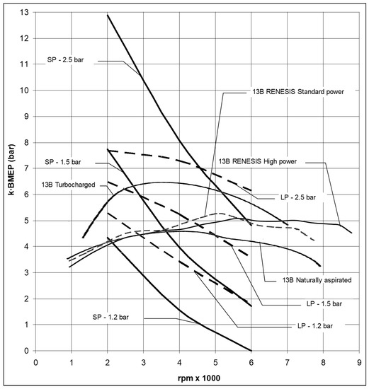
Figure 10.
Comparison of mean effective work per stroke [6,41].
BMWS ratio of SP 2.5 bar supercharging and turbocharged four-stroke engine at 2000 rpm is approximately 2.25. The same ratio of LP 2.5 bar supercharging and turbocharged four-stroke engine at 2000 rpm is approximately 1.35. This means that at 2000 rpm, SP and LP configurations with 2.5 bar supercharging have 125% and 35% higher power than the turbocharged four-stroke engine. However, in higher speeds (6000 rpm), there is no benefit for power density of two-stroke cycle with the given port geometries and charging pressures.
5.2. Charging, Discharging (Scavenging), and Mass Balance of Engine Cycle
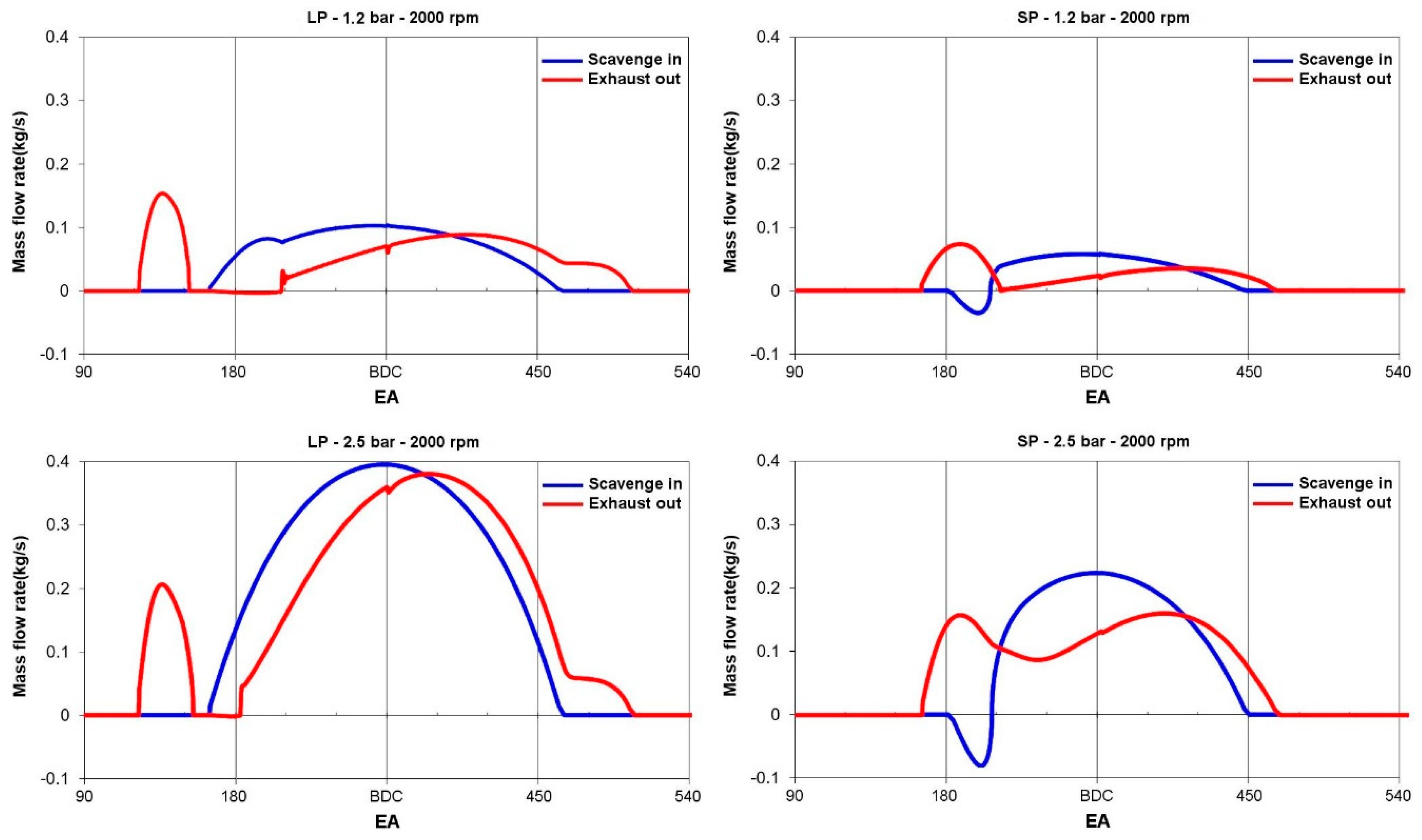
In two-stroke engines, port configuration is an important parameter for the charging and discharging of gases. In Figure 11, the flow rates of LP and SP ports are given for comparison. It must be noted that the discontinuity of exhaust flow at bottom death center (BDC) is due to the iteration beginning point and is negligible small for the whole cycle calculation procedure. As expected with increasing charging pressure, flow rates on exhaust and scavenging ports increase in every port configuration and speed condition. Similarly, large-port configuration has higher flow rates compared to small port. In LP configuration, there is not any back flow into the scavenging port for the whole charging pressure and speed range, and it minimizes the residual gas ratio (Figure 12). This is due to the rapid pressure drop in the combustion chamber, which can be seen from the indicated pressure in Figure 9. However, in SP configuration, there is always a back flow into the scavenging port at the beginning of the port opening, which results in a higher residual gas quantity. In LP configuration, after closing, the scavenge port forms a bulge of flow through the exhaust port while the combustion chamber volume decreases. The subsequent flow through the exhaust port results in a decrease of the charge mass in the combustion chamber as it is seen in Figure 12.
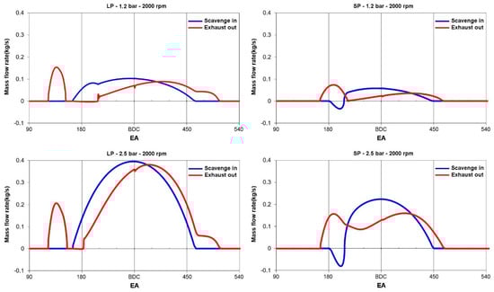
Figure 11.
Comparison of scavenge and exhaust port flow rates at different charging pressures for LP and SP geometry.
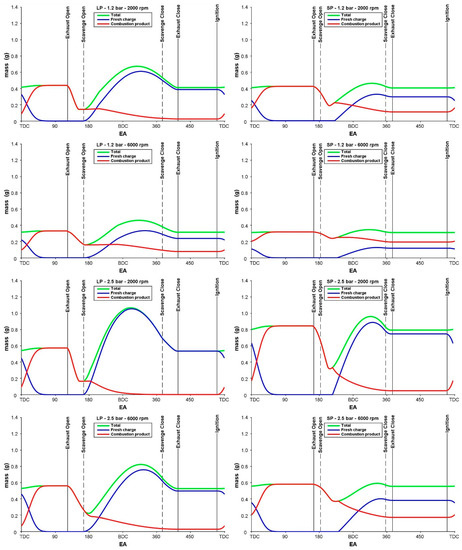
Figure 12.
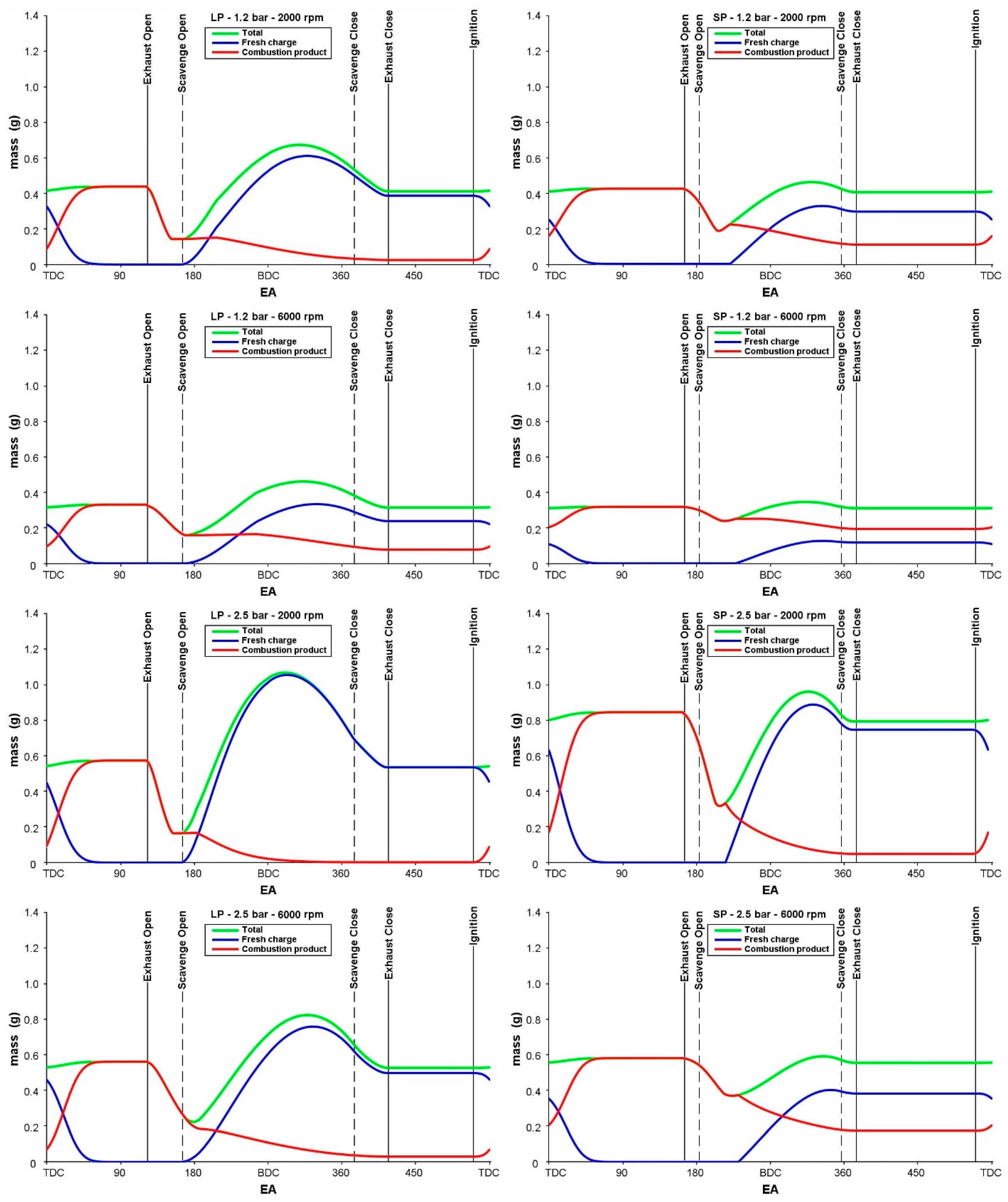
Change of fresh charge and combustion product mass in combustion chamber.
During the combustion process, fresh charge decreases and combustion products increase. At the same time, total mass in the combustion chamber slightly increases due to the fuel addition. The assumptions of fuel addition are as follows. Fuel mass delivery into the combustion chamber is defined with vibe function. Fuel in the combustion chamber is converted immediately to combustion products. By opening the exhaust port, mass in the combustion chamber decreases due to the outflow (exhaust blow down); hence, pressure in the combustion chamber decreases. In SP geometry, a slight increase of combustion products can be seen after the scavenge port opening. The increase of combustion products at the beginning of scavenging occurs due to the back flow and return of exhaust gases from the scavenge port into the combustion chamber.
In the second half of the charge exchange process, fresh charge from the scavenge port pushes combustion products to the exhaust port (perfect mixing scavenging). During this time, the mass of fresh charge increases while combustion products decrease in the combustion chamber. In LP configuration, after a maximum of fresh charge mass in the combustion chamber, a particular decrease can be observed at the end of gas exchange. This happens due to the loss of fresh charge on the exhaust channel. The loss of fresh charge in this geometry at low-speed and high-pressure-charge conditions is more evident in Figure 12. In the case of a large-port application, the amount of residual gas in the combustion chamber remains very low in all the operating conditions except the low-scavenging-pressure and high-speed conditions.
In the SP application, due to the early port closing, the amount of fresh charge pushed from the combustion chamber during compression period decreases. However, in all operating conditions except the high-charge-pressure and low-speed condition, the residual gas remaining from the previous cycle in the combustion chamber in SP configuration is high. Particularly with the low-charge-pressure and high-speed condition, the residual gas remaining in the combustion chamber is higher than the fresh charge amount. On the other hand, the amount of residual gas decreases significantly in the high-scavenging-pressure and low-speed condition, while the amount of fresh fill in the combustion chamber is highest. The result of this situation is also seen at the pressure levels in p-EA and p-V diagrams in Figure 9.
5.3. Scavenging Ratio and Efficiency
In this study, for the scavenging process as mentioned in Section 4, the filling and emptying method with simultaneous charging–discharging and perfect mixing scavenging assumption is applied. In this assumption, the entering air upon arrival in the chamber proceeds to mix “perfectly” with the exhaust gas. Pressure, temperature, and specific heat of the mixture are mean values for the complete combustion chamber. The resulting of exhaust gas effluent is composed solely of the mixed cylinder charge at that particular instant [26,30].
Figure 13 displays the scavenging ratio (SR) and efficiency (SE) of the two-stroke Wankel engine with SP and LP configuration at different scavenging pressure and engine speed. Definitions of SR and SE are given previously at the end of Section 4. As expected, the scavenging ratio of LP geometry is always higher in comparison to SP due to the larger port areas. In LP configuration at 2000 rpm and 2.5 bar charging pressure, SR value is approximately 2.4. This means that the amount of fresh charge sent from the scavenging port is 2.4 times the volume of the combustion chamber under the reference conditions. This indicates that a significant amount of fresh charge is lost from the exhaust port. As the speed of the engine increases, the scavenging ratio decreases rapidly due to the shorter scavenging time. In the case of SP configuration, the scavenging ratio is below 1 at all operating conditions. At high speed (6000 rpm) with SP geometry, the SR value is below 0.5, resulting in a sharp decrease of power production of the engine.
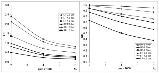
Figure 13.
Scavenging ratio (SR) and scavenging efficiency (SE) for LP and SP configuration.
Scavenging efficiency (SE) is the ratio of fresh charge to total charge in combustion chamber, which is also a measure for the ratio of residual gases (combustion product) in the combustion chamber. With LP and SP application, SE values are 0.98–0.76 and 0.80–0.38, respectively. According to these results, the fresh charge ratio is higher for LP configuration at all working conditions, while for SP application at higher speeds, the fresh charge ratio decreases sharply, and as the worst case at 1.2 bar charge pressure and 6000 rpm engine speed, it is lower than the residual gas.
In two-stroke engine literature, conventionally volume-based quantities are used as a marker of ideal behavior of scavenging in order to compare with the real state. Hence, a conversion from mass to volume has been made. In this ideal case, isothermal, isobaric process, and identical gas density (fresh charge, combustion chamber, exhaust) assumptions are valid [26]. Scavenging pressure and temperature are used as reference values. The two-stroke Wankel model calculation results are shown In Figure 14. With an increasing scavenging ratio, the purity in combustion chamber increases. However, at the same time, loss of fresh charge from the exhaust is practically at an unacceptable level. This can be seen especially at LP geometry and at high charging pressures. Additionally, this figure of volume-based scavenging ratio vs. efficiency confirms the model results related to perfect mixing assumption. In another study by Groff [42], the performance band of production reciprocating two-stroke engines is measured with a single-cycle scavenging apparatus. In this study, measurements reveal that the SEv and SRv values are distributed in the region bounded by perfect displacement and perfect mixing scavenging curves. However, based on the model results of present paper, it is obtained that the SEv and SRv values follow the perfect mixing scavenging curve closely. Thus, it is concluded that the model presented in present paper avoids overestimate the actual possible performance.
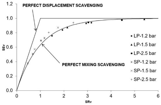
Figure 14.
Volumetric scavenging ratio (SRv) and efficiency (SEv) characteristics of model calculation.
6. Conclusions
The aim of this work is to analyze the improvement potential of the power density by applying two-stroke cycle on Wankel engine geometry. A single-zone thermodynamic model of the two-stroke Wankel engine has been developed to study its performance characteristics. Scavenging, exhaust port opening and closing timings are taken from conventional cross scavenging two-stroke reciprocating engines. Two different port configurations are modeled (LP—large ports, SP—small ports). Model calculations are made for stoichiometric mixture. Different scavenging pressure conditions (120–250 kPa) and engine speeds (2000–6000 rpm) are considered. From the geometry of the Wankel engine, port opening and closing timings, and hence port areas, are governed by rotor flank surface.
- For comparing the specific work for different type engine and cycles, the mean work per stroke—MWS—definition is proposed.
- The single-zone thermodynamic model of the two-stroke Wankel engine is validated according to combustion with the conventional four-stroke Wankel engine, cycle analysis, and scavenging characteristics with conventional reciprocating two-stroke engine data.
- The maximum pressure in the combustion chamber was 7.27–2.00 MPa. The geometric compression ratio of LP geometry is smaller, which leads to loss of indicated work area. Indicated specific work was 3.76–6.17 bar for low charging pressure and 8.41–14.28 bar for high charging pressure.
- The comparison between LP and SP shows that supercharging may be applied more effectively with SP geometry. Late opening and early closing port geometry (SP) with higher supercharging pressure has a higher performance at a low speed range. However, at high-speed operation, port areas become insufficient for gas exchange, which increases residual gas and reduces power. Early opening late closing port geometry (LP) with supercharging is more suitable at a higher speed range, but in this case, power demand for supercharging will be high.
- Port timing and area, charging pressure, and speed are the main factors that characterize output performance. These preliminary results show promising potential to increase power density by applying a two-stroke cycle on the Wankel engine. This is especially obvious at lower engine speed operations.
- This study is the first attempt to model and define the basic parameters and constraints of the two-stroke Wankel engine concept. In order to design a prototype, further research may concentrate on advanced port timings, design, and configurations. In addition, three-dimensional computational fluid dynamics (CFD) modelling should be used to investigate the effects of port geometries on the mixture within the combustion chamber.
Author Contributions
O.A.K. wrote the main body of the paper and analyzed the model data; F.M. prepared the main body of the model calculation. Both authors read and approved the manuscript.
Funding
This research was funded by TUBITAK (Scientific and Technological Research Council of Turkey) as a scientific research project, grant number 115M690.
Acknowledgments
The authors wish to thank Ozgur Oguz Taskiran for their support of preparation of this work.
Conflicts of Interest
The authors declare no conflict of interest.
Nomenclature
| a | Equidistance |
| asc | Scavenging port opened area |
| aex | Exhaust port opened area |
| Asc | Scavenging port total area |
| Aex | Exhaust port total area |
| Ac | Combustion chamber surface area |
| BDT | Bottom dead center |
| BMEP-pme | Brake mean effective pressure |
| BTDC | Before top dead center |
| BMWS | Brake mean effective work per stroke |
| CA | Crank angle degree |
| cv | Mean specific heat at constant volume |
| e | Eccentricity |
| EA | Eccentric Angle degree |
| FMEP-pmf | Mean frictional pressure |
| fpower | Power stroke frequency |
| hc | Heat transfer coefficient of combustion chamber |
| IMEP-pmi | Indicated mean effective pressure |
| IMWS | Indicated mean work per stroke |
| k | Isentropic exponent |
| kf | Work stroke fraction |
| LP | Large port |
| ne | Engine speed |
| p | Pressure |
| Pi | Indicated Power |
| Q | Heat |
| R | Generating Radius |
| R | Gas constant |
| SP | Small port |
| T | Temperature |
| TDC | Top dead center |
| ti | Instantaneous heat release time |
| tz | Heat release duration |
| V | Volume |
| Vh | Stroke volume |
| Wi | Work |
| Greek symbols | |
| e | Compression ratio |
| λ | Excess air coefficient |
| μ | Discharge coefficient |
| ρ | Density |
| ψ | Flow function |
| Subscripts abbreviations | |
| sc | Scavenging |
| ex | Exhaust |
| c | Combustion Chamber |
| w | Wall |
References
- Wankel, F. Einteilung der Rotations-Kolbenmaschinen; Deustche Verlags-Anstalt: Stuttgart, Germany, 1963. [Google Scholar]
- Yamamoto, K. Rotary Engine; Toyo Kogyo Co., Ltd.: Hiroshima, Japan, 1969. [Google Scholar]
- Bensinger, W.D. Rotationskolben-Verbrennungsmotoren; Springer: Berlin/Heidelberg, Germany, 1973. [Google Scholar]
- Ansdale, R.F. The Wankel RC Engine; Iliffe Books Ltd.: London, UK, 1968. [Google Scholar]
- Norbye, J.P. Wankel Engine: Design, Development, Applications; Chilton Book Co.: Philadelphia, PA, USA, 1971. [Google Scholar]
- Ohkubo, M.; Tashima, S.; Shimizu, R.; Fuse, S.; Ebino, H. Developed Technologies of the New Rotary Engine (RENESIS). SAE Paper No: 2004-01-1790. Available online: https://doi.org/10.4271/2004-01-1790 (accessed on 1 October 2019).
- Picard, M.; Hidaka, H.; Tian, T.; Nishino, T.; Arai, E.; Ohkubo, M. Visualization of the Rotary Engine Oil Transport Mechanisms; SAE 2014-01-1665. Available online: https://doi.org/10.4271/2014-01-1665 (accessed on 1 October 2019).
- Karatsu, Y.; Yun, J.H.; Kagava, R.; Minota, S.; Hashimoto, H.; Moriue, O.; Murase, E. Simultaneous Observation of Combustion in Optical Rotary Engine by Bottom View and Side View; SAE 2015-01-1891. Available online: https://doi.org/10.4271/2015-01-1891 (accessed on 1 October 2019).
- Muroki, T. Recent Technology Development of High-Powered Rotary Engine at Mazda. SAE Paper No: 841017. Available online: https://doi.org/10.4271/841017 (accessed on 1 October 2019).
- Fan, B.W.; Pan, J.F.; Pan, Z.H.; Tang, A.K.; Zhu, Y.J.; Xue, H. Effects of pocket shape and ignition slot locations on the combustion processes of a rotary engine fueled with natural gas. Appl. Therm. Eng. 2015, 89, 11–27. [Google Scholar] [CrossRef]
- Muroki, T.; Moriyoshi, Y.; Takagi, M.; Suzuki, K.; Imai, M. Research and Development of a Direct Injection Stratified Charge Rotary Engine with a Pilot Flame Ignition System. SAE Paper No: 2001-01-1844/4263. Available online: https://doi.org/10.4271/2001-01-1844 (accessed on 1 October 2019).
- Kawahara, N.; Tomita, E.; Hayashi, K.; Tabata, M.; Iwai, K.; Kagawa, R. Cycle-resolved measurements of the fuel concentration near a spark plug in a rotary engine using an in situ laser absorption method. Proc. Combust. Inst. 2007, 31, 3033–3040. [Google Scholar] [CrossRef]
- Fan, B.; Pan, J.; Tang, A.; Pan, Z.; Zhu, Y.; Xue, H. Experimental and numerical investigation of the fluid flow in a side-ported rotary engine. Energy Convers. Manag. 2015, 95, 385–397. [Google Scholar] [CrossRef]
- Zhang, Y.; Liu, J.; Zuo, Z. The Study of Turbulent Fluctuation Characteristics in a Small Rotary Engine with a Peripheral Port Based on the Improved Delayed Detached Eddy Simulation Shear-Stress Transport (IDDES-SST) Method. Energies 2018, 11, 642. [Google Scholar] [CrossRef]
- Warren, S.; Yang, D.C.H. Design of rotary engines from the apex seal profile. Mech. Mach. Theory 2013, 64, 200–209. [Google Scholar] [CrossRef]
- Wang, W.; Zuo, Z.; Liu, J. Miniaturization limitations of rotary internal combustion engines. Energy Convers. Manag. 2016, 112, 101–114. [Google Scholar] [CrossRef]
- Amrouche, F.; Erickson, P.; Park, J.; Varnhagen, S. An experimental investigation of hydrogen enriched gasoline in a Wankel rotary engine. Int. J. Hydrogen Energy 2014, 39, 8525–8534. [Google Scholar] [CrossRef]
- Fan, B.; Pan, J.; Liu, Y.; Zhu, Y. Effects of ignition parameters on combustion process of a rotary engine fueled with natural gas. Energy Convers. Manag. 2015, 103, 218–234. [Google Scholar] [CrossRef]
- Mai, H. Stirnflachendictung Für Innenachsige Rotationskolbenbrennkraftmaschinen. German Patent Application No. 1300123, 31 July 1969. [Google Scholar]
- Westland, M.W. Two-Stroke Rotary Internal Combustion Engine. U.S. Patent Application No. 1300123, 12 October 1993. [Google Scholar]
- Takashi, H. Two-Cycle Rotary Engine. Japan Patent Application No. 1300123, 30 June 1997. [Google Scholar]
- Malkaz, F. Analysıs of Wankel Type Two-Stroke Rotary Engıne. Master’s Thesis, Institute of Science and Technology, Istanbul Technical University, Istanbul, Turkey, 2011. [Google Scholar]
- Saracoglu, F. Improvement of the Cycle Analysis of two Stroke Wankel Engine. Master’s Thesis, Institute of Science and Technology, Istanbul Technical University, Istanbul, Turkey, 2012. [Google Scholar]
- Taskiran, O.O.; Calik, A.T.; Kutlar, O.A. Comparison of flow field and combustion in single and double side ported rotary engine. Fuel 2019, 254, 115651. [Google Scholar] [CrossRef]
- Finkelberg, L.; Kostuchenkov, A.; Zelentsov, A.; Minin, V. Improvement of Combustion Process of Spark-Ignited Aviation Wankel Engine. Energies 2019, 12, 2292. [Google Scholar] [CrossRef]
- Blair, G.P. Design and Simulation of Two Stroke Engines; SAE International: Warrendale, PA, USA, 1996. [Google Scholar]
- Kutlar, O.A.; Arslan, H. Alternative Ignition Systems; Book chapter; Lackner, M., Ed.; ProcessEng Engineering GmbH: Vienna, Austria, 2009. [Google Scholar]
- Fleck, B.J.; Fleck, R.; Kee, R.J.; Thornhill, D.J. The Evaluation of Discharge Coefficients in the Cylinders of High Performance Two-Stroke Engines. SAE Paper No: 2003-32-0029. Available online: https://doi.org/10.4271/2003-32-0029 (accessed on 1 October 2019).
- Akca, Y.E.; Biricik, S.; Isik, A.S. Calculation of Discharge Coefficient and Designing the Experimental Setup of Wankel Engines. Bachelor’s Thesis, Istanbul Technical University, Istanbul, Turkey, 2012. [Google Scholar]
- Horlock, J.H.; Winterbone, D.E. The Thermodynamics and Gas Dynamics of Internal-Combustion Engines; Oxford University Press: Oxford, UK, 1986; Volume II. [Google Scholar]
- Woschni, G. Universally Applicable Equation for the Instantaneous Heat Transfer Coefficient in the Internal Combustion Engine; SAE Paper No: 670931. Available online: https://doi.org/10.4271/670931 (accessed on 1 October 2019).
- Wilmers, G. Berechnung der Gasseitigen Vorgange in Kreiskolbenmotor System NSU-Wankel. Ph.D. Thesis, University of Stuttgart, Stuttgart, Germany, 1971. [Google Scholar]
- Vibe, I.I., II. Brennverlauf und Kreisprozess von Verbrennungsmotoren; Veb Verlag Technik: Berlin, Germany, 1970. [Google Scholar]
- Froede, W.; Jungbluth, G. Der Kreiskolbenmotor des NSU-Spider. ATZ 1966, 68, 150–155. [Google Scholar]
- Danieli, G.A.; Ferguson, C.R.; Heywood, J.B.; Keck, J.C. Predicting the Emissions and Performance Characteristics of a Wankel Engine; SAE Paper No: 740186. Available online: https://doi.org/10.4271/740186 (accessed on 1 October 2019).
- Tsao, K.C.; Losinger, D. Mass Burning Rate in a Rotary Engine; SAE Paper No: 741089. Available online: https://doi.org/10.4271/741089 (accessed on 1 October 2019).
- Kolchin, A.; Demidov, V. Design of Automotive Engines; Mir Publishers: Moscow, Russia, 1984. [Google Scholar]
- Chapra, S.C.; Canale, R.P. Numerical Methods for Engineers, 6th ed.; Mc Graw H.: New York, NY, USA, 2010. [Google Scholar]
- Basshuysen, R.; Stutzenberger, H.; Vogt, R. Unterschiede im Reibungsverhalten Zwischen Kreiskolbenmotoren und Hubkolbenmotoren von Audi. 1982. Available online: https://www.osti.gov/etdeweb/biblio/6772953 (accessed on 1 October 2019).
- Bozza, F.; Gimelli, A. A Comprehensive 1D Model for the Simulation of a Small-Size Two-Stroke SI Engine; SAE Paper No: 2004-01-0999. Available online: https://doi.org/10.4271/2004-01-0999 (accessed on 1 October 2019).
- Matsuda, I.; Tadokoro, T.; Kita, T.; Nakao, M. New Technology Employed for the Latest 13B-Rotary Engine; SAE Paper No: 900036. 1990. Available online: https://doi.org/10.4271/900036 (accessed on 1 October 2019).
- Groff, E. Automotive Two-Stroke-Cycle Engine Development in the 1980–1990′s; SAE Paper No: 2016-01-0177. Available online: https://doi.org/10.4271/2016-01-0177 (accessed on 1 October 2019).


© 2019 by the authors. Licensee MDPI, Basel, Switzerland. This article is an open access article distributed under the terms and conditions of the Creative Commons Attribution (CC BY) license (http://creativecommons.org/licenses/by/4.0/).