Article

Pure and Hydrocarbon Binary Mixtures as Possible Alternatives Working Fluids to the Usual Organic Rankine Cycles Biomass Conversion Systems

by
Costante M. Invernizzi
*,†,
Abubakr Ayub
,
Gioele Di Marcoberardino
and
Paolo Iora
Department of Mechanical and Industrial Engineering, University of Brescia, 25123 Brescia, Italy
*
Author to whom correspondence should be addressed.
Current address: Department of Mechanical and Industrial Engineering, University of Brescia, via Branze, 38, 25123 Brescia, Italy.
Energies 2019, 12(21), 4140; https://doi.org/10.3390/en12214140
Submission received: 29 September 2019 / Revised: 20 October 2019 / Accepted: 23 October 2019 / Published: 30 October 2019

Abstract

:
This study investigates the use of pure and hydrocarbons binary mixtures as potential alternatives working fluids in a usual biomass powered organic Rankine cycle (ORC). A typical biomass combined heat and power plant installed in Cremona (Italy) is considered as the benchmark. Eight pure hydrocarbons (linear and cyclic) and four binary mixtures of linear hydrocarbons were selected. The critical points of the binary mixtures at different composition were calculated using an in-house code developed in MATLAB© (R2018b) environment. Based on the critical point of a working fluid, supercritical and subcritical cycle configurations of ORC were analysed. A detailed thermodynamic comparison with benchmark cycle was carried out in view of cycle efficiency, maximum operating pressure, size of the turbine and heat exchangers. The supercritical cycles showed 0.02 to 0.03 points lower efficiency, whereas, subcritical cycles showed comparable efficiencies than that of the benchmark cycle. The cycles operating with hydrocarbons (pure and mixtures) exhibited considerably lower volume flow ratios in turbine which indicates lower turbine size. Also, size parameter of regenerator is comparatively lower due to the lower molecular complexity of the hydrocarbons. A noticeable increase in turbine power output was observed with change in composition of the iso-octane/n-octane binary mixture at the same thermodynamic efficiency.

1. Introduction

Biomass is largely used today for electricity and heat production. According to many analysts, as biomass can be easily stored, it could balance and regulate the different demands and the availability of the variable renewable energies in a context of high renewable energies uses. Other recognised positive characteristics of the biomass are its source diversification and the possibility of its local provision [1].
In 2013 the biomass energy consumption in the EU28 was about 105 Mtoe (the 2/3 of the total renewable energy production), the 75% of which used for the heat generation, the 13% for the electricity generation and the remaining 12% reserved to the transport fuels ([2], p. 33).
A sustainable future use of biomass for energy purposes has certainly to consider, among other things, the greenhouse gas emissions (direct and indirect) and has to explore the improving of the conversion efficiencies, with an increasing combined heat and electrical power production.
Anyway, in the future years the consumption of biomass for energy production is expected to grow, in different measure, according to the different policy options that will be adopted [2].
Today, in Europe about 290–300 biomass power plants are working, many of them in CHP configurations. Typically they are based on Rankine thermodynamic engines and the heat from the combustion of solid biomass is transferred to the working fluids by heat transfer oils. The Rankine cycle, at least for electrical power sizes less than 10 MW to 20 MW, employs usually an organic fluid, mostly siloxanes today [3,4,5]. Siloxanes are generally considered benign fluids, with a good thermal stability [6,7,8].
Generally, in addition to the favourable thermodynamic properties, to a low environmental impact and to a low toxicity, the cost of the working fluid is in any case an important economic parameter for the evaluation of the investment. As, for example, according to [9], 4000 L to 7000 L of working fluid are in an engine, according to its power.
As for any organic fluids a decomposition is unavoidable when the fluid works at relatively high temperatures, with serious consequences on the performances of the engine, (see, for example [10,11,12]), and when “contaminants” are present (water, oxygen or, mainly, lubrication oils), periodically, in a plant, a removing of the degradation products and a refilling are required. Beyond the first charge then, the cost of the new filling fluid, despite a partial recycle, could be very high [9].
The continuous investigation of different working fluids is so generally justifiable [13,14,15,16]. In this work we considered some hydrocarbons (pure or in mixtures) as potential alternative working fluids in biomass power plants.
Among the many possible working fluids available, hydrocarbons are the less expensive ones, they are flammable but most of them are considered mildly toxic. From the environmental point of view, they are considered “natural” fluids.
From the assumption to use—without any hypothetical modifications—a typical biomass boiler available today on the market, in this paper we explored—although quite preliminarly—the thermodynamic performances of supercritical and subcritical thermodynamic cycles with some hydrocarbons and mixtures of hydrocarbons as working fluids. As a comparison, we considered the performances and the design conditions of a biomass plant in Cremona (Italy) [17].
The furnace in Cremona has a design thermal outlet power of 6034 kW and the boiler has two circuits (see Figure 1): the high temperature circuit supplies 5503 kW to a heat transfer oil at 310 °C, the low temperature circuit provides 531 kW to a second mass flow of heat transfer oil at 252 °C. The working fluid in the associated thermodynamic cycles has then a maximum operative temperature of about 250 °C to 300 °C. The thermodynamic engines operates in CHP mode with a condensation temperature of about 100 °C.
These relatively low maximum temperatures and high condensation temperature combined with the relatively low thermal power available exclude the possibility to consider as alternative working fluid carbon dioxide (another “natural” fluid) or, for example, mixture of carbon dioxide and hydrocarbons. As a matter of fact, carbon dioxide should be reserved to power plants with very high power densities and to greater maximum to minimum temperatures ratio [18,19,20,21].
Some new refrigerants now available, have acceptable thermodynamic properties, good environmental parameters and a sufficient expectable thermal stability [22,23]. But unfortunately they are still very expensive.
In the past years many authors examined and proposed different approaches to the optimal working fluid selection, for low and high source temperatures. See, for example [24,25,26,27,28,29,30,31,32], in which, in many cases, advanced numerical multi-objective methods are used with the aim to select fluids optimising thermodynamic efficiencies and plant costs.
In this work we considered only some hydrocarbons suitable for this specific application, with the aim (1) to analyse supercritical and subcritical (with saturated vapour) thermodynamic cycles condensing at high temperature (70 °C to 100 °C), (2) to compare the results with a “conventional” option and (3) to explore and to show the potentialities of some mixtures.
Evidently, supercritical cycles could be anyway a valid option also in different situations, but, today, only a limited number of plants use this configuration. As an example, one supercritical geothermal ORC plant (the first in Europe) was in 2012 started up in Italy [33].

2. The Selection of The Working Fluids

In Table 1 are reported some design data for the biomass plant in Cremona (Italy). Assuming for the main cycle design parameters the values in Table 2 and MDM (octamethyltrisiloxane) as working fluid, we have simulated the thermodynamic cycle, obtaining so the reference case. All the thermodynamic calculations were carried out by Aspen Plus v9.0 using the PR EoS. For MDM cycle we obtained a gross efficiency of about 0.18: greater than the value in Table 1 (16.6%), but without considering the pressure losses. The available thermal power from the HT oil and its temperatures are fixed, according to the data in Table 1.
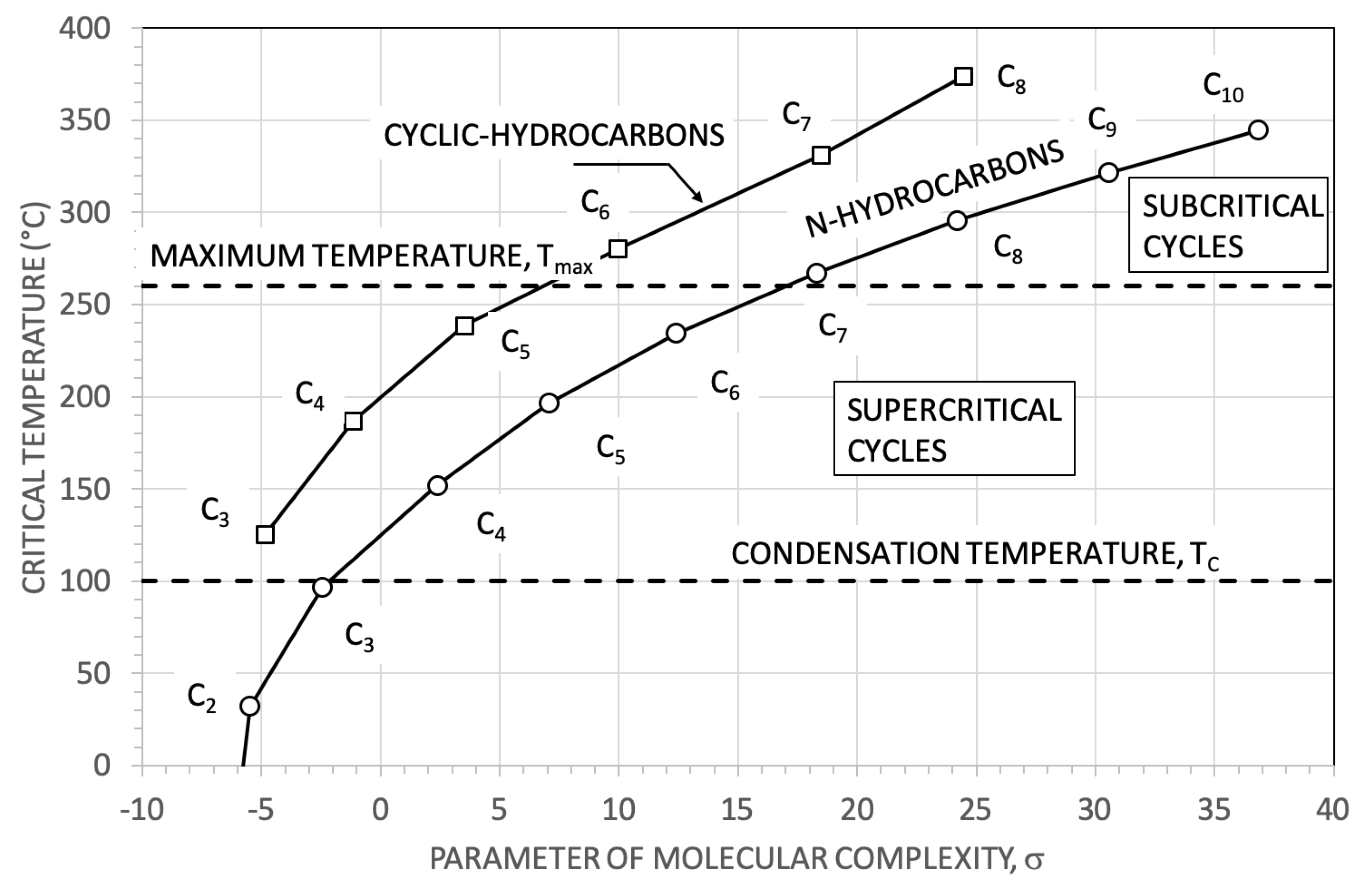
In Figure 2 there are the critical temperatures of the two hydrocarbon families here considered as a function of the parameter of molecular complexity σ .
The parameter σ , connected with the slope of the dew line in the T S diagram, depends primarily of the molar heat capacity C P of the working fluids and increases basically with it ([34], p. 109). An increasing of σ produces generally an isentropic expansion in the superheated vapour and, fixed a pressure expansion ratio, a reduction of the cooling of the expanding vapour (As a matter of fact, for example, for a perfect gas, an increasing of σ is strictly correlated with a reduction of the γ = C P / C V and, fixed a P / P , greater is σ , less is the cooling during an isentropic expansion ( T / T = P / P 1 1 / γ )).
As, in general, for the organic molecules, an increase in the molecular complexity is accompanied by a parallel increase in the molecular weight, an increase of σ is also associated to a reduction of the isentropic enthalpy drop in turbine (with a significant reduction of the number of stage of the turbine). On the other hand, an excessive reduction of the isentropic temperature drop in turbine, requires the use of large heat recovery exchangers (the regenerator) after the turbine, before the condenser. So it is not granted working fluids with high σ are always the best option.
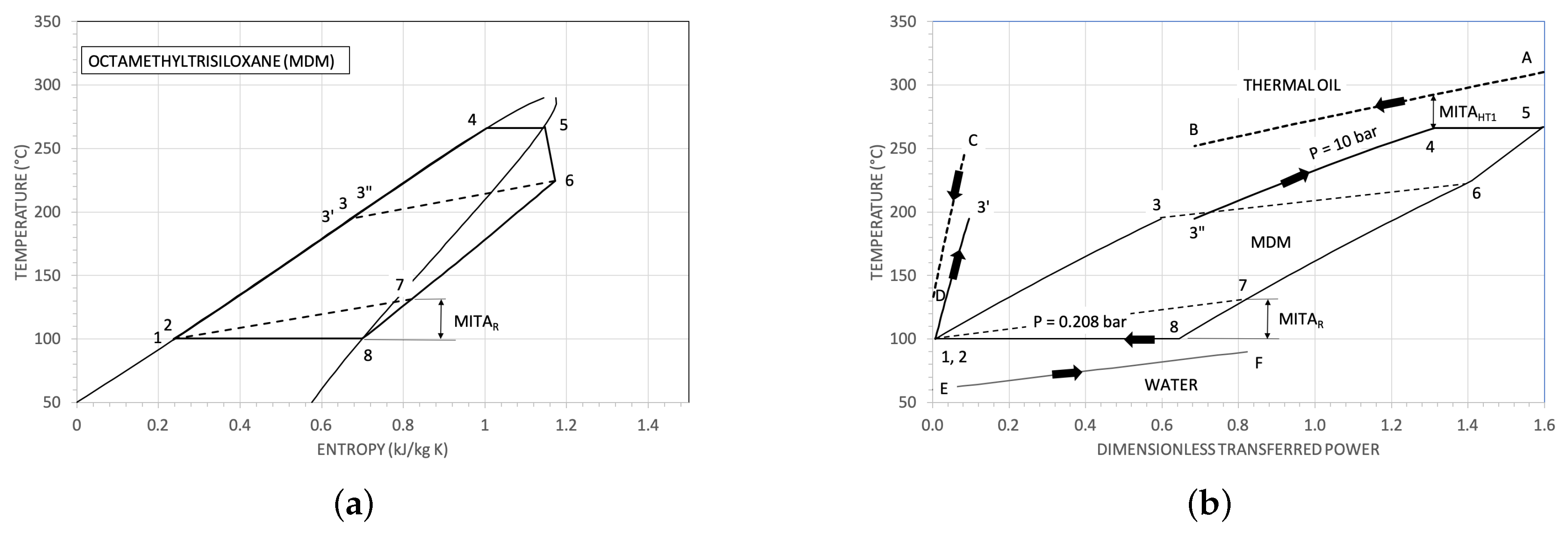
From this point of view, MDM is indeed, with σ = 48.8 , a good example. In Figure 3a, in the T S plane, the thermodynamic cycle assumed as reference is reported. The ratio between the recovered thermal power and the input thermal power (from the heat transfer oil) Q ˙ R / Q ˙ i n is about 0.6 and the ratio 2 Δ T / T 5 + T 6 of the corresponding isentropic expansion results equal to about 0.2 (with a pressure expansion ratio P 5 / P 6 of about fifty). In Figure 3b the same thermodynamic cycles and the assumed heat sources are reported just for a clarification of the process.
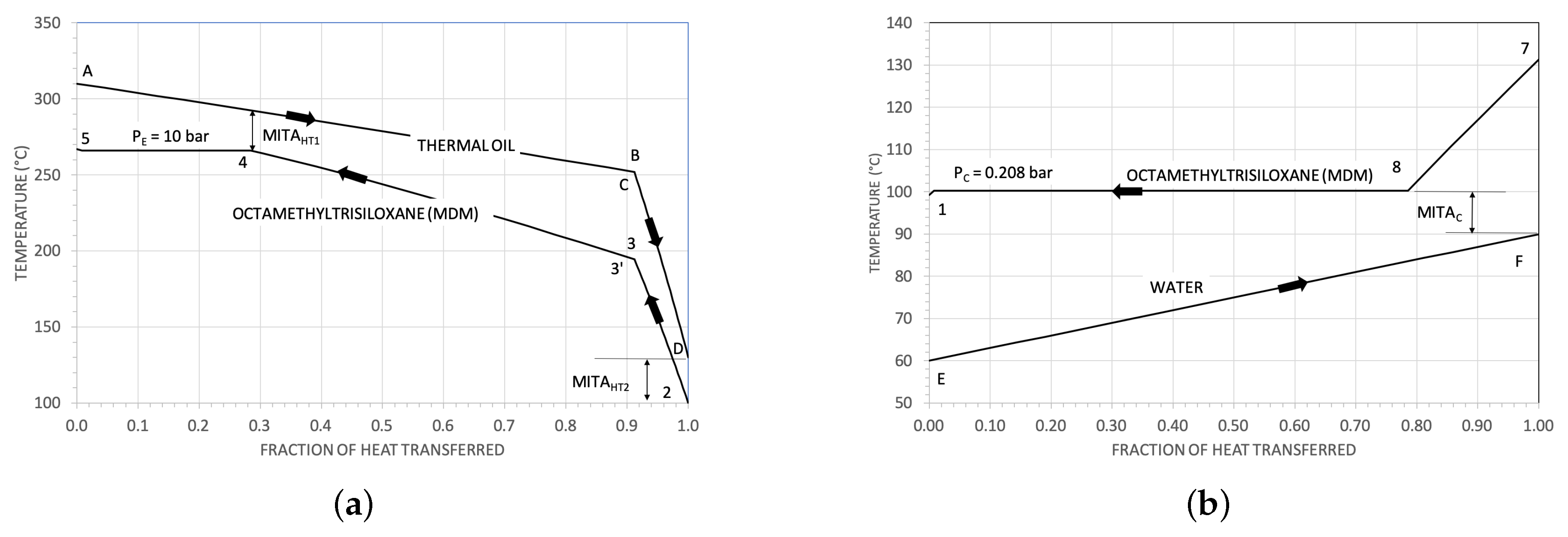
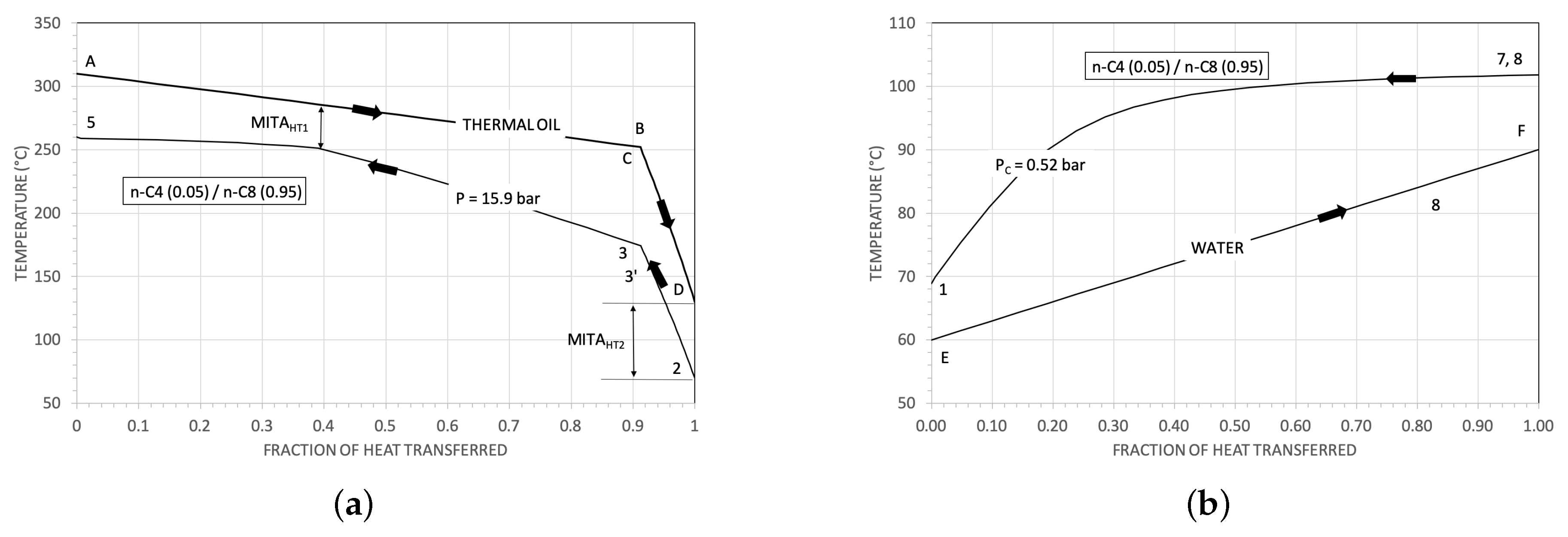
In Figure 4a, for the system using MDM as working fluid in the thermodynamic cycle, the heat transfer diagram for the oil heat exchangers HT 1 and HT 2 is reported. In Figure 4b there is the corresponding diagram for the condenser.
Fixed a critical temperature, the parameter σ for cyclic hydrocarbons results appreciably lower than that of the corresponding normal (linear) hydrocarbons. For example, at T c r 200 °C, cyclo-butane has σ = −1.1 and n-pentane has σ equal to about 7.0 (see Figure 2).
On the other hand, fixed the number of carbon in the molecule, the molecular mass for cyclic and linear hydrocarbons is basically the same, and lower than that of MDM (236.53).
With the design parameters in Table 1 and Table 2, the maximum, T m a x , and the minimum T C operating temperatures of the (pure) working fluid in the engine result equal to 260 °C and to 100 °C respectively. As the reference cycle operates in a CHP mode, in the following we assumed cooling water available between 60 and 90 Celsius degree.
For supercritical cycles, the maximum operating temperature has to be higher than the critical one; working fluids with a critical temperature greater than the assumed maximum temperature are suitable for sub-critical (with saturated vapour) thermodynamic cycles. The working fluids we preliminarily considered are then those in Table 3.
In case of mixtures in sub-critical thermodynamic cycles, T m a x = T E , d e w and T C = T C , d e w : the maximum temperature equals the dew temperature at the evaporation pressure and T C equals the dew condensation temperature.
The critical pressures P c r of the cyclical hydrocarbons are appreciably greater than that of the linear hydrocarbons. For this reason, in this work, the mixtures we considered are mixture of linear hydrocarbons only (see Table 3).
The mixture n-butane/n-hexane is representative of a mixture thermodynamic suitable for supercritical cycles (given the maximum and the minimum temperatures here considered); the mixtures of iso- and n-octane, that of n-butane and n-octane and that of n-hexane and n-octane are suitable for sub-critical cycles. For these mixtures, the chosen components are those typically considered as the main constituents of commercial petrol (iso-octane, in particular, is produced and largely used to reduce the detonation of the standard petrol).
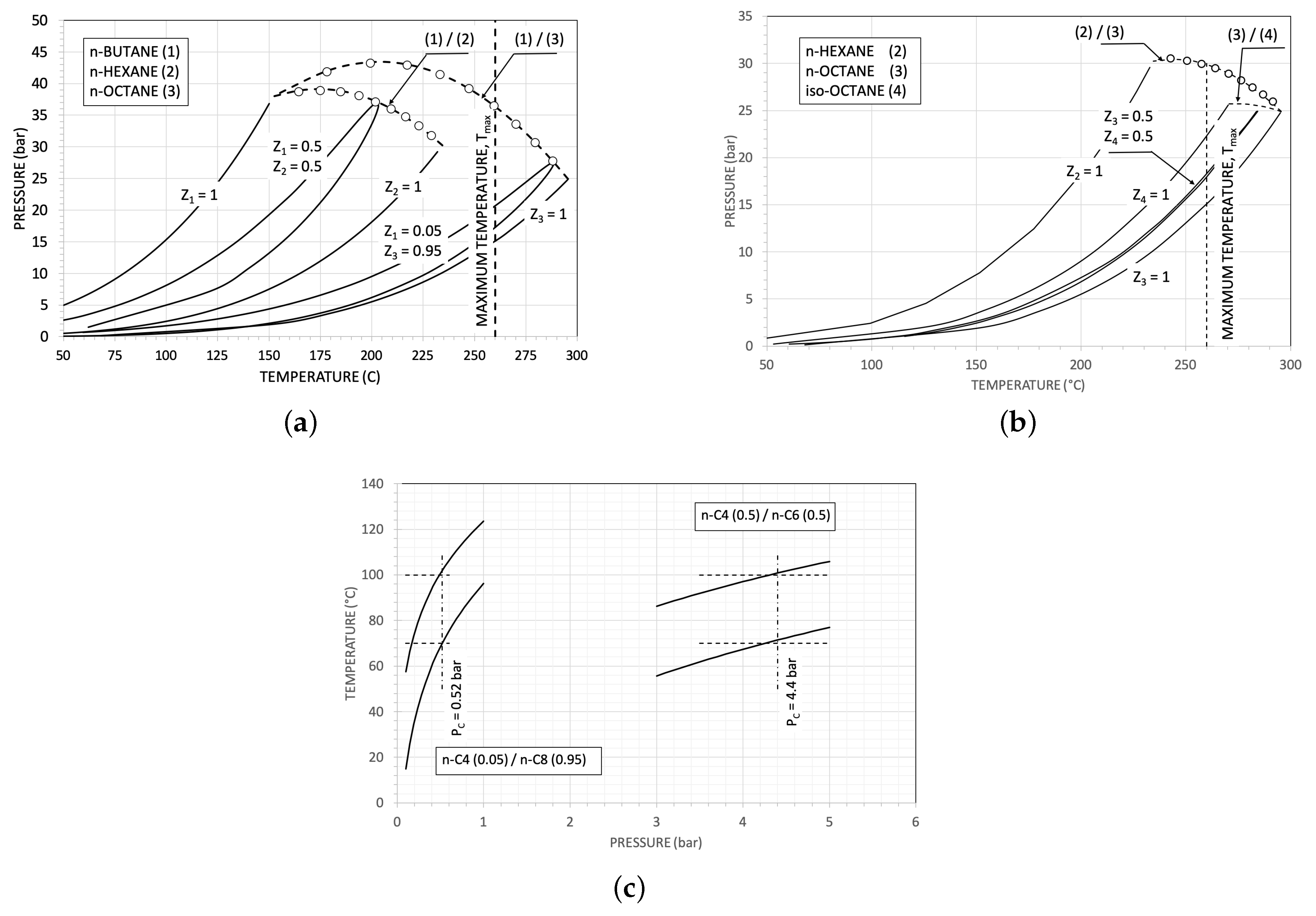
In Figure 5a,b the critical loci of the mixtures here considered are reported. In the Figure are also some P T envelops relative to some different composition.
The critical loci are computed using an in-house code developed in MATLAB© (ver R2018b) environment with the help of INTLAB toolbox [36]. In particular, the critical point model given in [37] is used in conjunction with the PR EoS (Peng-Robinson Equation of State) [38], expressed the model in the form of non-linear system of equations with intensive variables; the roots of these equations are critical point(s) of a mixture.
The code developed in this study used the formulation of ref [38] and computes the critical points of the considered binary mixtures using interval analysis root finding technique available in INTLAB toolbox. The code requires pure fluid properties including critical points, molar composition, acentric factors and binary interaction parameter ( k 1 , 2 ) corresponding to PR EoS as an input information to compute the critical points of a binary mixture. In addition, the initial interval which covers the minimum and maximum range in which the root can occur is also required.
In the selection of the mixtures composition we enjoined a dew temperature of around 100 °C and a “temperature glide” of about 30 °C, having us cooling water available between 60 °C and 90 °C.
Finally, a crucial parameter for the choice of a working fluid is its thermal stability. About the hydrocarbons here considered, it seems reasonable to assume a safe operative maximum temperature of 250 °C to 280 °C [39,40,41,42], according to the fixed approach temperature difference of 50 °C in the heat exchanger HT 1 .
As a general rule [26,43], fixed the maximum temperature T A of a finite thermal capacity heat source, the best thermodynamic cycle is for a working fluid with a critical temperature roughly equal to T A . However, in our case, the source thermal power is fixed and we imposed instead the maximum cycle temperature T m a x , so better is the thermodynamic efficiency, greater will be the useful mechanical power.

3. The Thermodynamic Results

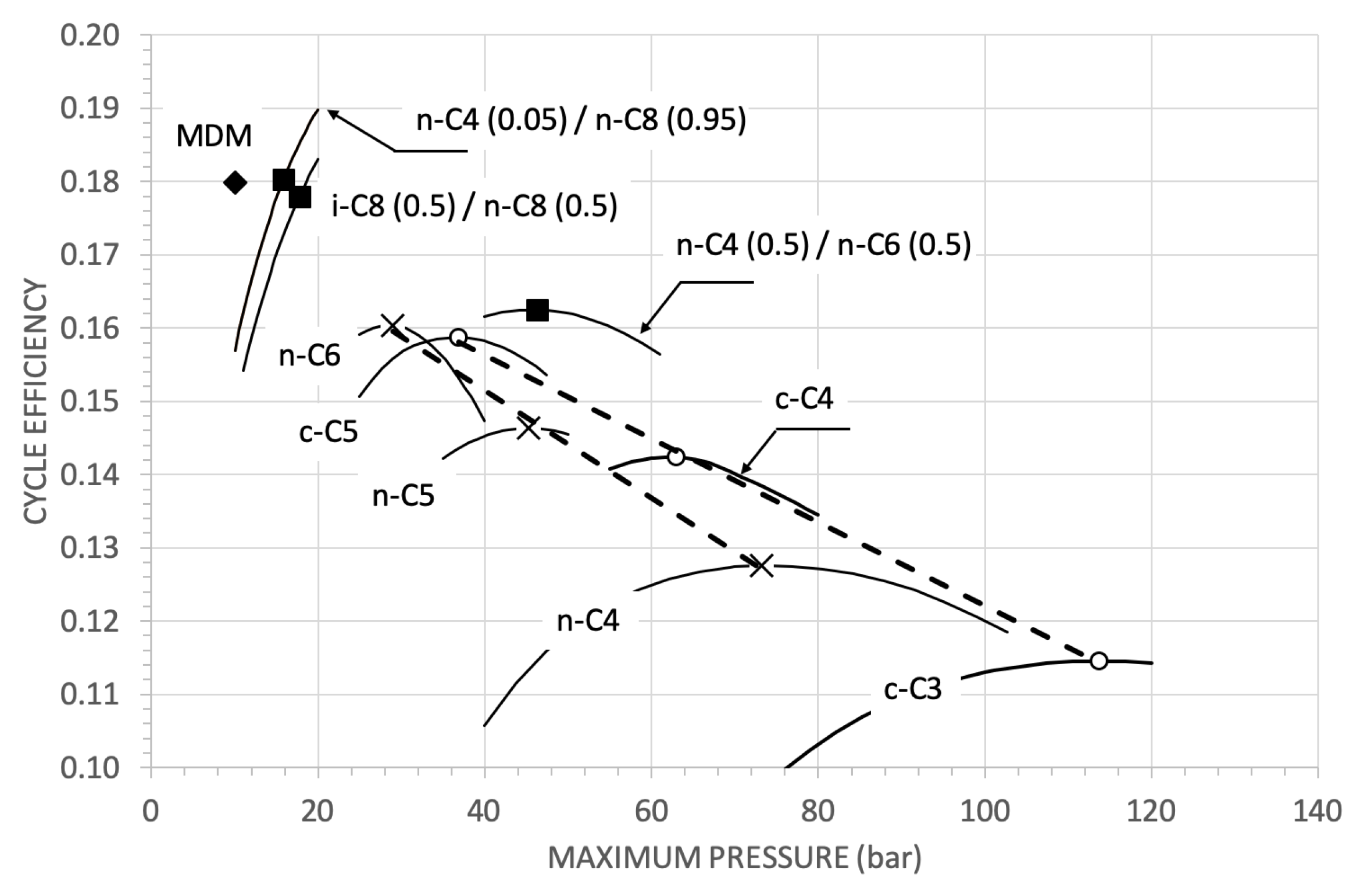
The thermodynamic cycle efficiencies as a function of the maximum pressure P m a x for pure linear, cyclic and for some hydrocarbon mixtures are reported in Figure 6. The efficiency value of MDM is reported as a comparison.
The super-critical cycles have generally (with the design constraints here assumed) a low thermodynamic efficiency. As a general trend, the efficiency increases with the critical temperature of the working fluid. For example, c-C3 (with a T c r / T A ratio of 0.68) has an optimal efficiency of 0.115, n-C6 (with a T c r / T A ratio of 0.87) has an optimal efficiency of 0.160.
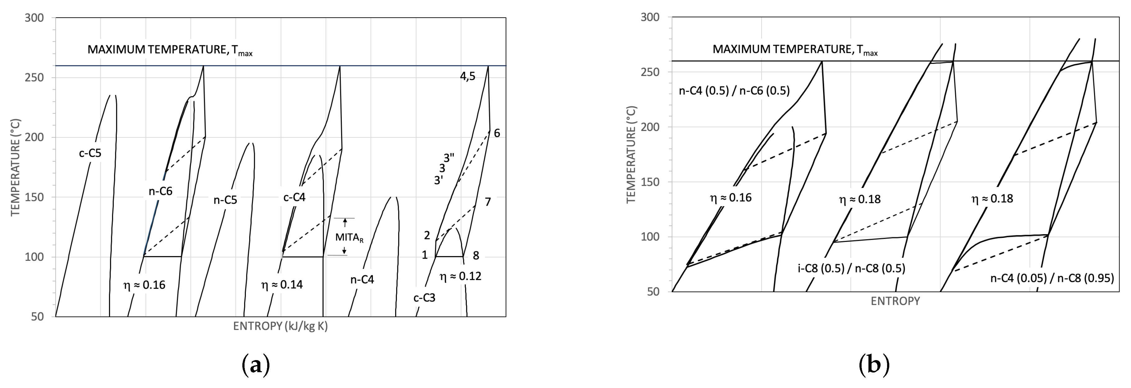
In Figure 7a, in the T S thermodynamic plane, there are some of the considered super-critical cycles with pure working fluids. Fixed the maximum temperature T m a x , increasing the critical temperature of the working fluid, the optimal maximum pressure approaches the critical one and the ratio W between the pump power W ˙ P and the sum W ˙ P + W ˙ T decreases. This is, for the super-critical cycles, the primary reason of their relatively poor efficiency. For example, set W 0 = 1 for the reference MDM cycle, the cycle with c-C3 has W / W 0 7 ( η = 0.115 ) and the cycle with n-C6 has W / W 0 2 ( η = 0.160 ).
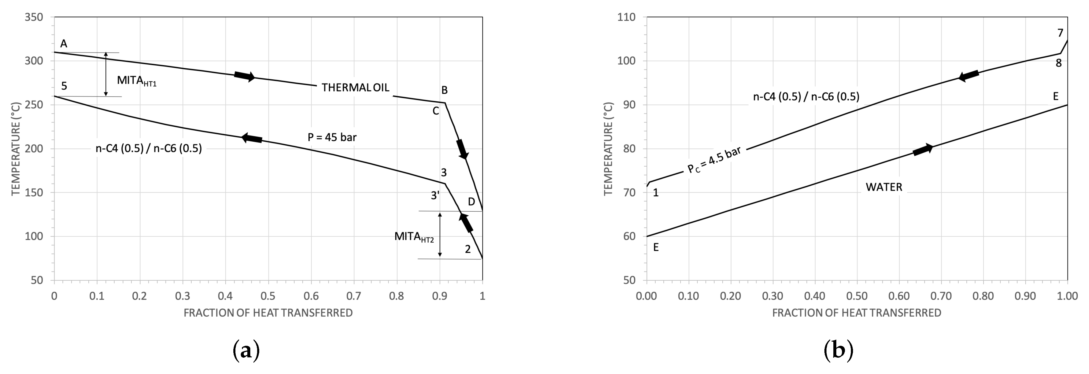
The mixture n-C4 (0.5)/n-C6 (0.5) (see Figure 5c) at a condensing pressure P E of 4.4 bar has a dew temperature of about 100 °C and a temperature “glide” of about 30 °C. So, this particular composition results useful, in our case, to reduce the thermodynamic losses in the condenser. The corresponding thermodynamic cycles (in Figure 7b in the T S plane) has an efficiency η of about 0.164 at P m a x of 45 bar (see Figure 6). In Figure 8a,b there are the heat transfer T Q ˙ diagrams for the oil heat exchangers and for the condenser, respectively. The heat transfer diagram in the condenser results actually better than that of the MDM cycle, but the high temperature heat transfer diagram results worse. This fact, combined with the relatively high W / W 0 3 , gives an efficiency η anyway lower than that of the benchmarked cycle.
In Figure 6 there are also the efficiencies for two sub-critical (saturated) cycles using the mixture i-C8 /(0.5)/n-C8 (0.5) and the mixture n-C4 (0.05)/n-C8 (0.95) as working fluids. The highlighted points are those with a maximum temperature T E , d e w of 260 °C. The corresponding cycles are reported in Figure 7b in the T S plane.
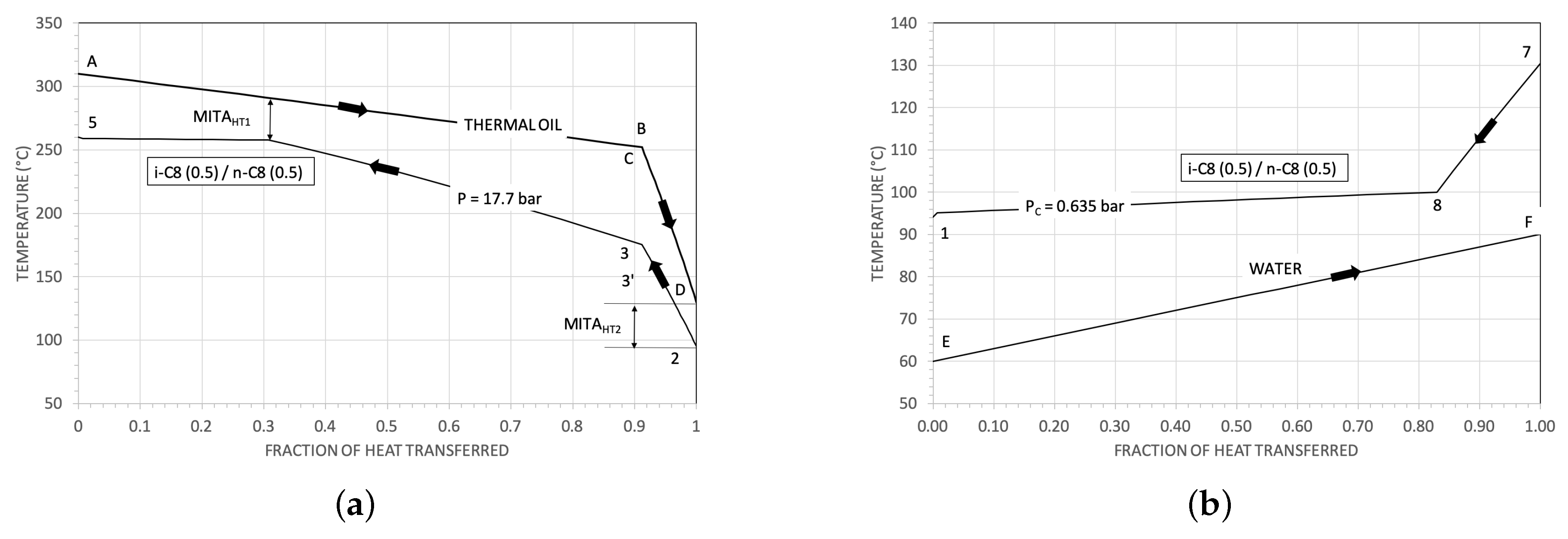
The resulting efficiencies are good (as a matter of fact comparable with that of the cycle with MDM as working fluid). The temperature profiles in the T Q ˙ diagrams (see Figure 9 and Figure 10) are also satisfying.
The mixture n-C6/n-C8 has a critical temperature greater than T m a x only for a molar fraction of n-C6 lower than 0.5 and the equi-molar mixture ( T c r = 272 °C) gives a thermodynamic cycle efficiency of 0.18 at P E , d e w = 23 bar and at P C , d e w = 0.775 bar.
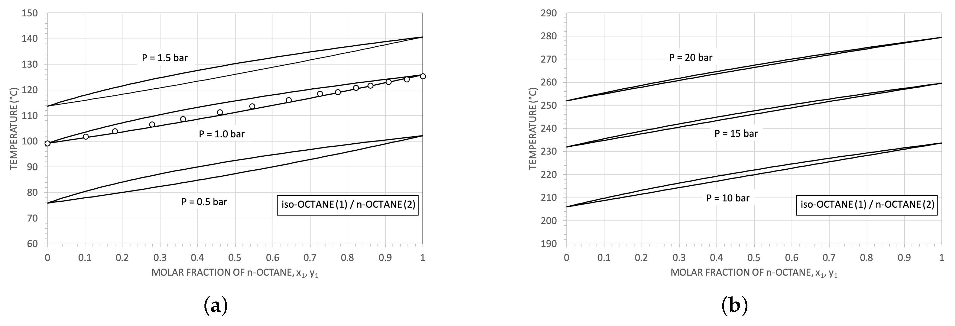
The mixture i-C8/n-C8 seems particularly interesting. At every composition it is like a quasi-azeotropic mixture (see Figure 5b, Figure 9 and Figure 11). It is a good example of the variations of thermodynamic behaviours of a mixture with two similar constituents and an example on how the main features of the thermodynamic cycles can be changed by the composition of the working fluid.
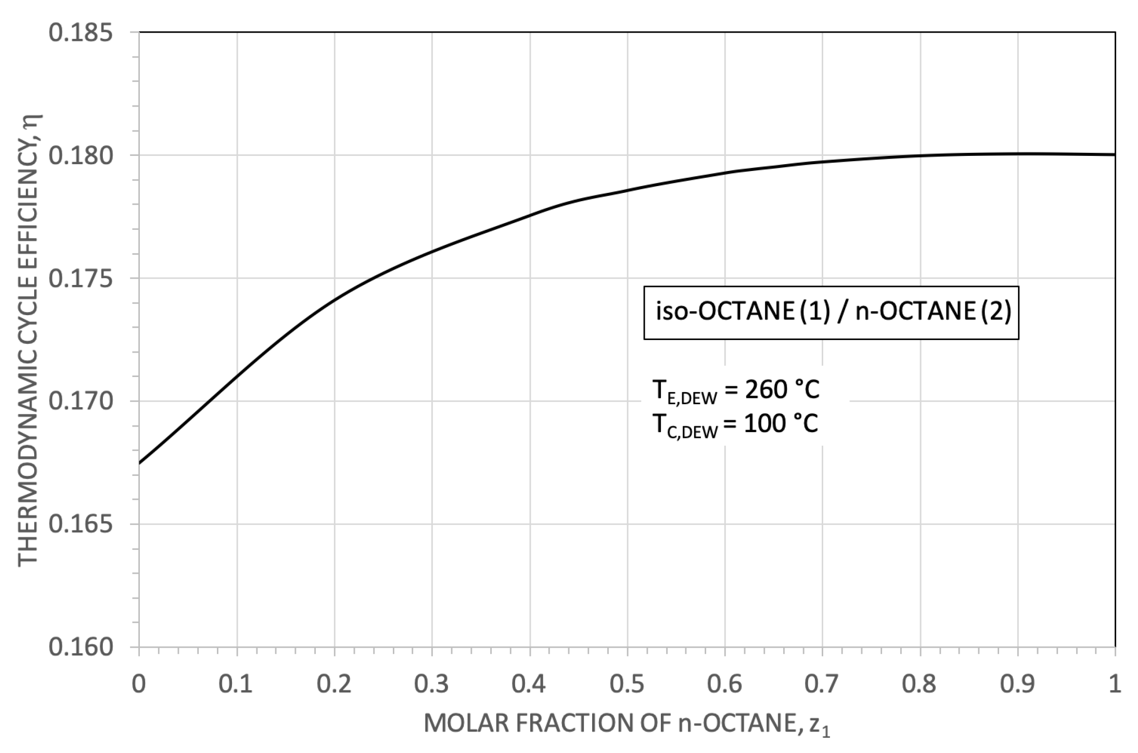
As explicative results, in Figure 12 the thermodynamic cycle efficiency for different mixture compositions is reported. The efficiency increases from 0.167 ( z 1 = 0 , pure iso-octane) to 0.18 ( z 1 = 1 , pure n-octane). From z 1 equal to 0 to 1, the efficiency η changes of about 7 per cent; in the interval 0.5 to 1 the variation is less than 1 per cent.

3.1. Some Results for the Heat Exchangers

For the condenser, the ratio U A / W ˙ T W ˙ P , between U A and the net power W ˙ T W ˙ P , results (for the cycles with the mixture i-C8 (0.5)/n-C8 (0.5)) equal to 0.192 K−1, as against a value of 0.170 K−1 in the case of MDM cycle (+13 per cent).
For the oil—working fluid heat exchangers ( HT 1 and HT 2 ), the ratio U A / W ˙ T W ˙ P results 0.00916 K−1 and 0.111 K−1, respectively, as against values of 0.0114 K−1 (−20 per cent) and 0.137 K−1 (−20 per cent) for MDM.
Owing to the smaller parameter σ , the ratio U A / W ˙ T W ˙ P for the recuperator heat exchanger (the regenerator) results, for the thermodynamic cycle with mixture i-C8 (0.5)/n-C8 (0.5)), lower than about 40 percent compared to that of the MDM cycle ( 0.0666 K−1, against 0.108 K−1).

3.2. Turbomachinery Considerations

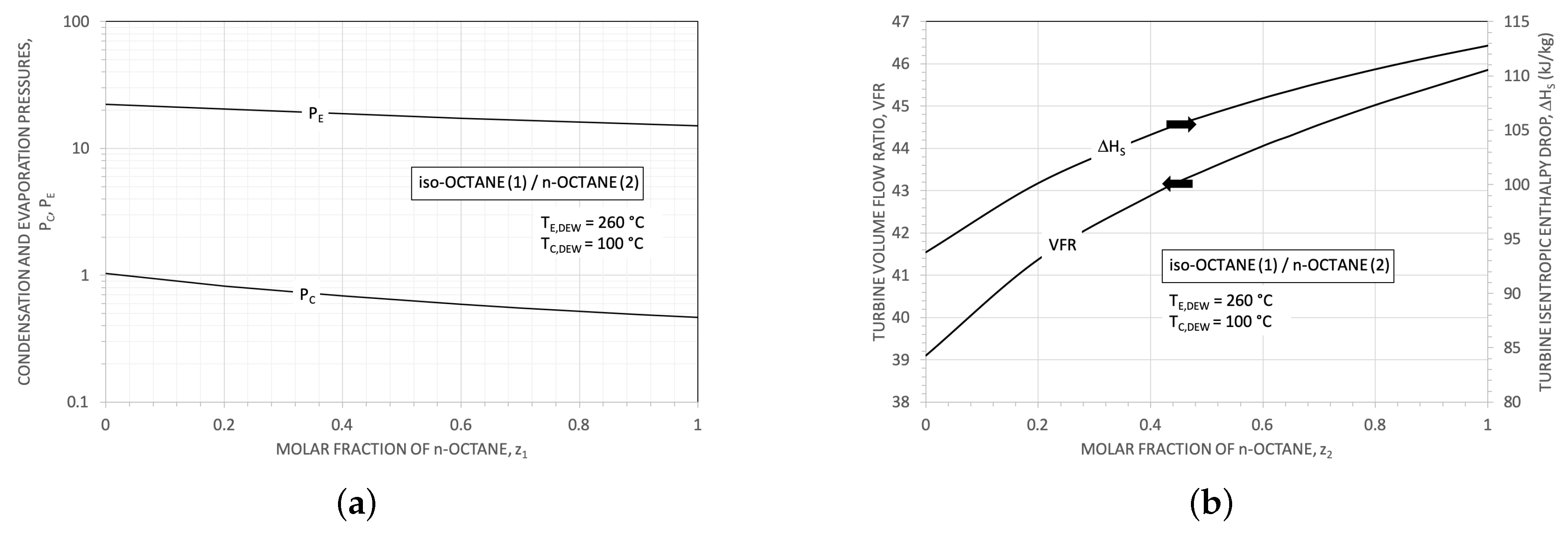
In Figure 13a the condensation pressure (at T C , d e w equal to 100 °C) and the evaporation temperature (at T E , d e w equal to 260 °C) are reoprted as a function of the molar fraction of n-octane.
Strictly correlated with the turbine expansion pressure ratio ( P E , d e w / P C , d e w ) are the turbine volumetric flow ratio V F R = V ˙ o u t / V ˙ i n and the turbine isentropic enthalpy drop Δ H S , see Figure 13b. The enthalpy drop and the V F R (by means of the so called size parameter S P ) are closely connected with the number of turbine stages and with its rotational speed [45].
Volume flow ratios greater than about 20–30 are difficult to realise with a single turbine (axial) stage: supersonic (absolute and relative) velocities and high flaring angles increase shock and profile losses and one has to resort to a multi-stage solution. High V F R associated with low S P (less than 0.1) require multi-stages turbine at high rotating speed and, as a general trend, the result is a turbine difficult to design. For each pair of S P and V F R , exist an optimal value of the specific speed n s and, consequently, an optimal number of revolutions N and an optimal specific diameter d s .
For the mixture i-C8/n-C8 the V F R increases from 39 to 46, with a corresponding Δ H S increasing from 94 KJ kg−1 to 112 KJ kg−1. As a comparison, for the reference cycle with MDM, one obtains V F R equal to about 75 and Δ H S equal to about 63 KJ kg−1.
To summarise the results, in Table 4 are reported some significant data relating to optimal thermodynamic cycles. The considered super-critical cycles have an efficiency from 0.02 to 0.03 points lower than that of the MDM cycle. On the other hand, the turbine volume flow ratios result significantly lower than that of the MDM. Therefore an efficient single stage turbine could be designed, but, owing to the very high operating pressures, with a net power of tens of MW.
The sub-critical cycles, have thermodynamic efficiencies comparable with that of the benchmarked cycle with turbine volume flow ratios of about 30 per cent lower.
Assuming a rotating speed of 3000 rpm and an isentropic power of about 1333 kW, we estimated the approximate main characteristics of the MDM turbine. The used approximated method, assuming ideal turbines stages and real gas effects, is briefly described in [46]. Some results are in Table 5. The turbine, due to its high overall V F R , has two stages, with a rotor mean diameter of about 90 cm. The first stage is with total admission even if its h / D ratio reaches its lower limit value.
Accepting the similitude, the turbines with n-octane and iso-octane (at the same rotating speed) have roughly an isentropic power of about 5600 kW and of 7500 kW, respectively. Their main estimated geometrical data are in Table 5.
Mixtures of i-C8 and n-C8, in different composition, allow so to design turbines with significant different useful powers with practically the same thermodynamic efficiency (see Figure 12 and Figure 13).

4. Conclusions

In the paper was investigated the possibility to use hydrocarbons (pure fluids or mixtures) in Rankine cycles recovering heat from biomass furnaces. As working hypothesis, we assume a standard biomass oil furnace and, as a reference thermodynamic cycle, a saturated Rankine one with MDM as working fluid. Super-critical and sub-critical thermodynamic cycles were investigated.
Notwithstanding the adopted simplifications, from the previous presented results the following conclusions can be drawn:
  • the super-critical cycles, mainly owing to their high pumping power relative to the expansion useful power, have basically lower thermodynamic efficiencies than the reference cycle. In the better cases, for example, 0.16 against 0.18. The use of mixtures, allowing in principle an optimisation of the T Q ˙ diagram in condensation, performs a bit better than the pure fluids. But, at least in the considered cases, always worse of about 1.5 points percent than the reference thermodynamic efficiency;
  • the considered saturated cycles have thermodynamic efficiencies completely comparable with the reference value.
Among the many conceivable different mixtures of hydrocarbons we identifyied here mixtures of iso-octane and n-octane. These mixtures have modest temperatures “glides” at every composition and the corresponding mixture critical temperatures result always greater than the maximum assumed working temperature (260 °C). So, saturated cycles are always possible for every composition.
An interesting result is that, varying the composition the thermodynamic efficiency results in practice constant (at least starting from an n-octane molar fraction greater than 0.5). Whereas, fixed the minimum and the maximum temperatures, because of the condensation and the evaporation pressures variation, the turbine power (fixed the number of revolution) change noticeably with the composition. For example, at 3000 rpm, a two optimised stage turbine giving about 1000 kW with MDM, could produce about 4200 kW and 5600 kW with n-octane and with iso-octane respectively. The mixture composition results so an additional degree of freedom in the design of Rankine engines using organic fluids.
As for the dimension of the heat exchangers, we evaluated some results of U A per unit of produced power. Without the values of the overall heat transfer coefficients it is impossible determine the true total area A. Anyway, due to the smaller molecular complexity of the hydrocarbons compared to that of MDM, the regenerator should results with less surface.
In short, hydrocarbons as working fluids (pure or in mixtures), at least for the specific considered application, from the thermodynamic point of view, seem a good option.

Author Contributions

Conceptualization, C.M.I.; methodology, C.M.I.; software, A.A., C.M.I.; investigation, A.A., C.M.I.; writing—original draft preparation, A.A., C.M.I.; revision and final editing, G.D.M., P.I.

Funding

This research received no external funding.

Conflicts of Interest

The authors declare no conflict of interest.

Abbreviations

The following abbreviations, symbols and subscripts are used in this manuscript:
Atotal heat transfer area, (m2)
CHPCombined and Heat Power
d s specific diameter = D Δ H S 0.25 V ˙ o u t , S 0.5 = D S P
Dmean turbine diameter (m)
M I T A R Minimum Internal Temperature Approach in the recuperator (°C)
M I T A H T Minimum Internal Temperature Approach in the HT heat exchanger (°C)
MDMOctamethyltrisiloxane
n s specific speed = 2 π N 60 V ˙ o u t , S 0.5 Δ H S 0.75 = 2 π N 60 S P Δ H S 0.5
Nspeed revolution (rpm)
P C condensation pressure (bar)
P c r critical pressure (bar)
P m a x maximum cycle pressure (bar)
PR EoSPeng-Robinson Equation of State
Q ˙ i n inlet thermal power (kW)
Q ˙ R recovered thermal power (kW)
Rgas constant (kJ kg−1 K−1)
Sentropy (kJ kg−1 K−1)
S P size parameter for a stage of axial turbine V ˙ o u t , S 0.5 / Δ H S 0.25 (m)
Ttemperature (°C or K)
T A maximum temperature of the heat source (thermal oil) (°C or K)
T c r critical temperature (°C or K)
T r reduced temperature = T / T c r
Uoverall heat transfer coefficient (W m−2 K−1)
V ˙ volumetric flow rate (m3 s−1)
V F R isentropic flow ratio = V ˙ o u t , S / V ˙ i n = ρ i n / ρ o u t
W ˙ mechanical or electrical power (kW)
W ˙ S isentropic power (kW)
zmolar fraction
Δ H S isentropic turbine work (kJ kg−1)
Δ T temperature difference (°C)
η T turbine efficiency
η P pump efficiency
ρ density (kg m−3)
σ parameter of molecular complexity = T c r R d S s v d T T r = 0.7
subscripts
Ccondensation
d e w dew conditions
Eevaporation
i n inlet
m a x maximum
o u t outlet
Ppump
Sisentropic conditions
svsaturated vapour
Tturbine

References

  1. Anonymous. State of Play o the Sustainability of Solid and Gaseous Biomass Used for Electricity, Heating and Cooling in the EU. Commission Staff Working Document. Available online: https://ec.europa.eu/energy/en/topics/renewable-energy/biomass (accessed on 8 August 2019).
  2. Bogaert, S.; Pelkmans, L.; van den Heuvel, E.; Devriendt, N.; De Regel, S.; Hoefnahels, R.; Junginger, M.; Resch, G.; Liebmann, L.; Mantau, U.; et al. Sustainable and Optimal Use of Biomass for Energy in the EU beyond 2020—Final Report. May 2017. Available online: https://ec.europa.eu/energy/sites/ener/files/documents/biosustain_report_final.pdf (accessed on 8 August 2019).
  3. Angelino, G.; Invernizzi, C. Cyclic Methylsiloxanes as Working Fluids for Space Power Cycles. Trans. ASME J. Sol. Energy Eng. 1993, 115, 130–137. [Google Scholar] [CrossRef]
  4. Obernberger, I.; Biedermann, F. Combustion and Gasification of Solid Biomass for Heat and Power Production in Europe – State-of-the-Art and Relevant Future Development. In Proceedings of the 8th European Conference on Industrial Furnaces and Boilers, Vilamoura, Portugal, 25–28 March 2008; Keynote Lecture. CENERTEC: Vilamoura, Portugal, 2008; pp. 1–24. [Google Scholar]
  5. Weith, T.; Heberle, F.; Preißinger, M.; Brüggermann, D. Performance of Siloxane Mixtures in a High-Temperature Organic Rankine Cycle Considering the Heat Transfer Characteristics during Evaporation. Energies 2014, 7, 5548–5565. [Google Scholar] [CrossRef]
  6. Preißinger, M.; Brüggermann, D. Thermal Stability of Hexamethyldisiloxane (MM) for High-Temperature Organic Rankine Cycle (ORC). Energies 2016, 9, 183. [Google Scholar] [CrossRef]
  7. Keulen, L.; Landolina, C.; Spinelli, A.; Iora, P.; Invernizzi, C.; Lietti, L.; Guardone, A. Thermal stability of hexamethyldisiloxane and octamethyltrisiloxane. Energy Part B 2018, 165, 868–876. [Google Scholar] [CrossRef]
  8. Dai, X.; Shi, L.; Qian, W. Thermal stability of hexamethyldisiloxane (MM) as a working fluid for organic Rankine cycles. Int. J. Energy Res. 2019, 43, 896–904. [Google Scholar] [CrossRef]
  9. Erhart, T.G.; Gölz, J.; Eicker, U.; van der Broek, M. Working Fluid Stability in Large-Scale Organic Rankine Cycle-Units Using Siloxanes—Long-Term Experiences and Fluid Recycling. Energies 2016, 9, 422. [Google Scholar] [CrossRef]
  10. Invernizzi, C.M.; Bonalumi, D. Thermal stability of organic fluids for Organic Rankine Cycle systems. In Organic Rankine Cycle (ORC) Power Systems. Technologies and Applications; Macchi, E., Astolfi, M., Eds.; Woodhead Publishing: Duxford, UK, 2017; pp. 123–151. [Google Scholar]
  11. Rajabloo, T.; Bonalumi, D.; Iora, P. Effect of a partial decomposition of the working fluid on the performances of ORC power plants. Energy 2017, 133, 1013–1026. [Google Scholar] [CrossRef]
  12. Dai, X.; Shi, L.; An, Q.; Qian, W. Influence of alkane working fluid decomposition on supercritical organic Rankine cycle systems. Energy 2018, 153, 422–430. [Google Scholar] [CrossRef]
  13. Angelino, G.; Colonna di Paliano, P. Multicomponent Working Fluids For Organic Rankine Cycles (ORCs). Energy 1998, 23, 449–463. [Google Scholar] [CrossRef]
  14. Drescher, U.; Brüggermann, D. Fluid selection for the Organic Rankine Cycle (ORC) in biomass power and heat plants. Appl. Therm. Eng. 2007, 27, 223–228. [Google Scholar] [CrossRef]
  15. Invernizzi, C.M.; Iora, P.; Bonalumi, D.; Macchi, E.; Roberto, R.; Caldera, M. Titanium tetrachloride as novel working fluid for high temperature Rankine Cycles: Thermodynamic analysis and experimental assessment of the thermal stability. Appl. Therm. Eng. 2016, 107, 21–27. [Google Scholar] [CrossRef] [Green Version]
  16. Invernizzi, C.; Binotti, M.; Bombarda, P.; Di Marcoberardino, G.; Iora, P.; Manzolini, G. Water Mixtures as Working Fluids in Organic Rankine Cycles. Energies 2019, 12, 2629. [Google Scholar] [CrossRef]
  17. Salogni, A.; Alberti, D.; Metelli, M.; Bertanzi, R. Operation and maintenance of a biomass fired—Organic Rankine Cycle—CHP plant: the experience of Cremona. Energy Procedia 2017, 129, 668–675. [Google Scholar] [CrossRef]
  18. Invernizzi, C.M.; van der Stelt, T. Supercritical and real gas Brayton cycles operating with mixtures of carbon dioxide and hydrocarbons. Proc. Inst. Mech. Eng. Part A J. Power Energy 2012, 226, 682–693. [Google Scholar] [CrossRef]
  19. Manente, G.; Lazzaretto, A. Innovative biomass to power conversion systems based on cascaded supercritical CO2 Brayton cycles. Biomass Bioenergy 2014, 69, 155–168. [Google Scholar] [CrossRef]
  20. Astolfi, M.; Lasala, S.; Macchi, E. Selection Maps For ORC And CO2 Systems For Low-Medium Temperature Heat Sources. Energy Procedia 2017, 129, 971–978. [Google Scholar] [CrossRef]
  21. Invernizzi, C.M. Prospects of Mixtures as Working Fluids in Real-Gas Brayton Cycles. Energies 2017, 10, 1649. [Google Scholar] [CrossRef]
  22. Invernizzi, C.M.; Iora, P.; Preißinger, M.; Manzolini, G. HFOs as substitute for R-134a as working fluids in ORC power plants: A thermodynamic assessment and thermal stability analysis. Appl. Therm. Eng. 2016, 103, 790–797. [Google Scholar] [CrossRef]
  23. Huo, E.; Liu, C.; Xin, L.; Li, X.; Xu, X.; Li, Q.; Wang, S.; Dang, C. Thermal stability and decomposition mechanism of HFO-1336mzz(Z) as an environmental friendly working fluid: Experimental and theoretical study. Int. J. Energy Res. 2019, 1–14. [Google Scholar] [CrossRef]
  24. Papadopoulos, A.I.; Stijepovic, M.; Linke, P. On the systematic design and selection of optimal working fluids for Organic Rankine Cycles. Appl. Therm. Eng. 2010, 30, 760–769. [Google Scholar] [CrossRef]
  25. Toffolo, A.; Lazzaretto, A.; Manente, G.; Paci, M. A multi-criteria approach for the optimal selection of working fluid and design parameters in Organic Rankine Cycle systems. Appl. Energy 2014, 121, 219–232. [Google Scholar] [CrossRef]
  26. Vivian, J.; Manente, G.; Lazzaretto, A. A general framework to select working fluid and configuration of ORCs for low-to-medium temperature heat sources. Appl. Energy 2015, 156, 727–746. [Google Scholar] [CrossRef]
  27. Braimakis, K.; Preißinger, M.; Brüggermann, D.; Karellas, S.; Panopoulos, K. Low grade waste heat recovery with subcritical and supercritical Organic Rankine Cycle based on natural refrigerants and their binary mixtures. Energy 2015, 88, 80–92. [Google Scholar] [CrossRef]
  28. Astolfi, M.; Martelli, E.; Pierobon, L. Thermodynamic and technoeconomic optimization of Organic Rankine Cycle systems. In Organic Rankine Cycle (ORC) Power Systems. Technologies and Applications; Macchi, E., Astolfi, M., Eds.; Woodhead Publishing: Duxford, UK, 2017; pp. 173–249. [Google Scholar]
  29. Scaccabarozzi, R.; Tavano, M.; Invernizzi, C.M.; Martelli, E. Comparison of working fluids and cycle optimization for heat recovery ORCs from large internal combustion engines. Energy 2018, 158, 396–416. [Google Scholar] [CrossRef]
  30. Miao, Z.; Zhang, K.; Wang, M.; Xu, J. Thermodynamic selection criteria of zeotropic mixtures for subcritical organic Rankine cycle. Energy 2019, 167, 484–497. [Google Scholar] [CrossRef]
  31. Yaǧli, H.; Koç, Y.; Koç, A.; Görgülü, A.; Tandiroǧlu, A. Parametric optimization and exergetic analysis comparison of subcritical and supercritical organic Rankine cycke (ORC) for biogas fuelled combined heat and power (CHP) engine exhaust gas waste heat. Energy 2016, 111, 923–932. [Google Scholar] [CrossRef]
  32. Imran, M.; Haglind, F.; Lemort, V.; Meroni, A. Optimization of organic Rankine cycle power systems for waste heat recovery on heavy-duty vehicles considering the performance, cost, mass and volume of the system. Energy 2019, 180, 229–241. [Google Scholar] [CrossRef]
  33. Bonafin, J.; Di Schio, C.R.; Duvia, A. Turboden, a Presentation of Recent Worldwide Developments and Large-Scale Geothermal ORC Power-Plants. Trans. Geotherm. Resour. Counc. 2015, 39, 827–831. [Google Scholar]
  34. Invernizzi, C.M. Closed Power Cycles—Thermodynamic Fundamentals and Applications; Springer: London, UK, 2013. [Google Scholar]
  35. Hicks, C.P.; Young, C.L. The Gas-Liquid Critical Properties of Binary Mixtures. Chem. Rev. 1975, 75, 119–175. [Google Scholar] [CrossRef]
  36. Rump, S.M. INTLAB—INTTerval LABoratory. In Developments in Reliable Computing; Csendes, T., Ed.; Springer Science+Business Media: Dordrecht, The Netherlands, 1999; pp. 77–104. [Google Scholar]
  37. Heidemann, R.A.; Khalil, A.M. The calculation of critical points. AIChE J. 1980, 26, 769–779. [Google Scholar] [CrossRef]
  38. Michelsen, M.L.; Heidemann, A.M. Calculation of critical points from cubic two-constant equation of state. AIChE J. 1981, 27, 521–523. [Google Scholar] [CrossRef]
  39. Pasetti, M.; Invernizzi, C.M.; Iora, P. Thermal stability of working fluids for organic Rankine cycles: An improved survey method and experimental results for cyclopentane, isopentane and n-butane. Appl. Therm. Eng. 2014, 73, 764–774. [Google Scholar] [CrossRef]
  40. Invernizzi, C.M.; Iora, P.; Manzolini, G.; Lasala, S. Thermal stability of n-pentane, cyclo-pentane and toluene as working fluids in organic Rankine engines. Appl. Therm. Eng. 2017, 121, 172–179. [Google Scholar] [CrossRef]
  41. Dai, X.; Shi, L.; An, Q.; Qian, W. Chemical kinetics method for evaluating the thermal stability of Organic Rankine Cycle working fluids. Appl. Therm. Eng. 2016, 100, 708–713. [Google Scholar] [CrossRef]
  42. Dai, X.; Shi, L.; An, Q.; Qian, W. Screening of hydrocarbons as supercritical ORCs working fluids by thermal stability. Energy Convers. Manag. 2016, 126, 632–637. [Google Scholar] [CrossRef]
  43. Invernizzi, C.; Bombarda, P. Thermodynamic performance of selected HCFCS for geothermal applications. Energy 1997, 22, 887–895. [Google Scholar] [CrossRef]
  44. Bromiley, E.C.; Quiggle, D. Vapor-Liquid Equilibria of Hydrocarbon Mixtures. Ind. Eng. Chem. 1933, 25, 1136–1138. [Google Scholar] [CrossRef]
  45. Macchi, E.; Astolfi, M. Axial flow turbines for Organic Rankine Cycle applications. In Organic Rankine Cycle (ORC) Power Systems. Technologies and Applications; Macchi, E., Astolfi, M., Eds.; Woodhead Publishing: Duxford, UK, 2017; pp. 299–319. [Google Scholar]
  46. Bombarda, P.; Invernizzi, C. Binary liquid metal-organic Rankine cycle for small power distributed high efficiency systems. Proc. IMechE Part A J. Power Energy 2015, 229, 192–209. [Google Scholar] [CrossRef]
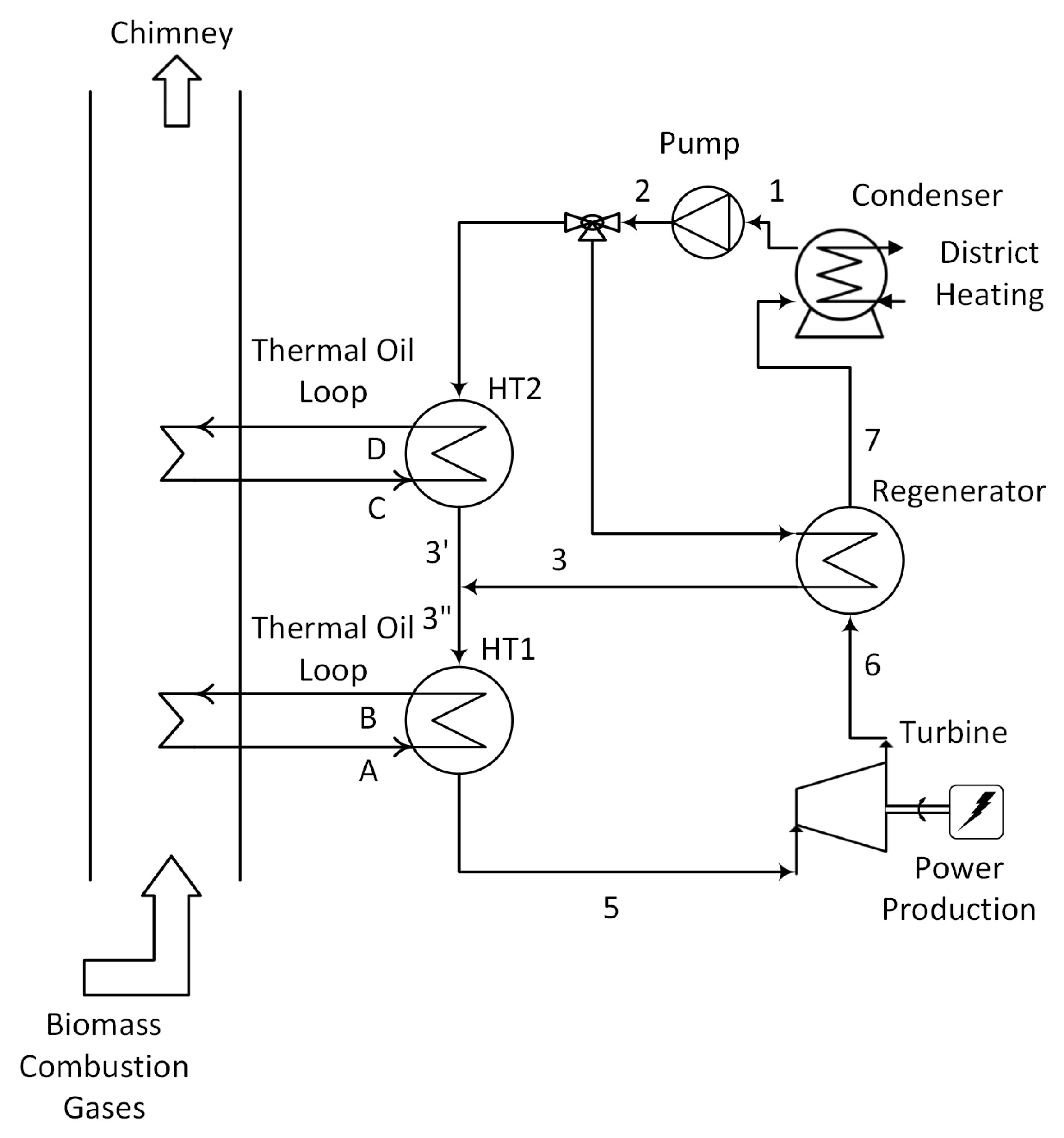
Figure 1. The reference plant scheme assumed as a reference case. Adapted from [17].
Energies 12 04140 g001
Figure 2. Critical temperature as a function of the molecular complexity parameter for linear (normal) hydrocarbons and cyclic hydrocarbons.
Energies 12 04140 g002
Figure 3. (a) Reference thermodynamic cycle with MDM as working fluid in a T S plane. (b) The heat sources (thermal oil in HT 1 and in HT 2 loops and the cooling water) and the thermodynamic cycle in a temperature—dimensionless power plane.
Energies 12 04140 g003
Figure 4. T Q ˙ diagrams for the reference case. (a) T Q ˙ diagram for the oil heat exchangers H T 1 and H T 2 . The mass flow rates of the hot oil are different in the two heat exchangers H T 1 and H T 2 . So, from the point C on, the slope of the temperature changes. (b) T Q ˙ diagram for the condenser.
Energies 12 04140 g004
Figure 5. Critical loci for some mixtures (dotted lines). The white circle are from experimental literature data [35]. (a) Critical loci and some P T envelops for mixtures of n-C4/n-C6 and n-C4/n-C8. (b) Critical loci and P T envelops for mixtures of n-C6/n-C8 and n-C8/i-C8. (c) P T envelops for two mixtures around a dew temperature of 100 °C.
Energies 12 04140 g005
Figure 6. Thermodynamic cycle efficiency as a function of the maximum pressure.
Energies 12 04140 g006
Figure 7. (a) Configuration of some (supercritical) thermodynamic cycles in the T S plane (pure fluids); (b) Configuration of some thermodynamic cycles in the T S plane for hydrocarbon mixtures.
Energies 12 04140 g007
Figure 8. Temperature - Thermal power exchanged ( T Q ˙ diagrams) for the the equimolar mixture n-C4/n-C6. (a) in the hot oil heat exchangers. (b) in the condenser.
Energies 12 04140 g008
Figure 9. Temperature-Thermal Power Exchanged for the cycle operating with the mixture i-C8 (0.5)/n-C8 (0.5) in the (a) High Temperature heat exchangers. (b) Condenser.
Energies 12 04140 g009
Figure 10. Temperature-Thermal Power Exchanged for the cycle operating with the mixture n-C4 (0.05)/n-C8 (0.95) in the (a) High Temperature heat exchangers. (b) Condenser.
Energies 12 04140 g010
Figure 11. T xy diagrams for the mixture i-C8 (0.5)/n-C8 (0.5) at different pressures. The white circles are from experimental literature data [44], and are reported as a comparison with the calculated values.
Energies 12 04140 g011
Figure 12. Thermodynamic cycle efficiency for the mixture iso-octane/n-octane as a function of the molar fraction of n-octane. The considered cycles are all subcritical with saturated vapour.
Energies 12 04140 g012
Figure 13. For a mixture of iso-octane/n-octane: (a) The trend of the evaporation and of the condensation pressures with the molar fraction of n-octane. (b) The variation of the isentropic enthalpy drop in turbine and of the isentropic volume flow ratio with the molar fraction of n-octane.
Energies 12 04140 g013
Table 1. Design data for the ORC plant in Cremona. The data are from [17].
ParameterReference Value
Thermal oil power- HT 1 loop (kW)5503
Thermal oil temperature- HT 1 loop (inlet, T A /outlet, T B ) (°C)310/252
Thermal oil power- HT 2 loop (split loop) (kW)531
Thermal oil temperature- HT 2 loop (inlet, T C /outlet, T D ) (°C)252/130
Overall thermal power to ORC (kW)6034
Cooling water temperature (inlet/outlet) (°C)65/105
Generator power (kW)999
Gross efficiency (%)16.6
Table 2. Design parameters assumed for the calculations.
ParameterAssumed Value
pressure lossesnone
minimum internal temperature approach in the recuperator, M I T A R (°C)30
turbine efficiency (a) η T 0.8
pump efficiency (a) η P 0.75
evaporation pressure for MDM (bar)10
condensation temperature (°C)100
cooling water temperature (inlet/outlet) (°C)60/90
approach temperature difference in HT 1 oil heat exchanger (b) (°C)50
(a) including the mechanical efficiency; (b) for the considered super-critical cycles.
Table 3. Some parameters for the considered fluids (pure fluids and mixtures) suitable for super-critical and sub-critical thermodynamic cycles. MDM is reported as a comparison.
Fluid
(Pure Fluid or Mixture)
Critical Temperature
T cr (°C)
Critical Pressure
P cr (bar)
Vapour Pressure
at 100 °C (bar)
Binary Interaction
Parameter, k 1 , 2
n-butane, n-C4151.9737.9615.33
n-pentane, n-C5196.5533.75.91
n-hexane, n-C6234.4530.252.45
cyclo-propane, c-C3125.155.7536.68
cyclo-butane, c-C4186.8549.811.27
cyclo-pentane, c-C5238.4545.084.15
n-C4 (0.5)/n-C6 (0.5) (a)203.637.064.4 (b)−0.0056
n-octane, n-C8295.5424.90.466
iso-octane, i-C8270.6525.71.04
i-C8 (0.5)/n-C8 (0.5) (a)284.9125.510.635 (b)−0.00570
n-C4 (0.05)/n-C8 (0.95) (c)292.0226.20.505 (b)0.00660
n-C6 (0.5)/n-C8 (0.5)272.34 (a)28.74 (a)0.775 (b)−0.01675
MDM (d)291.2514.60.2061
(a) at an equi-molar composition ( z 1 = z 2 = 0.5 ); (b) at the dew point; (c) molar composition: z 1 = 0.05 , z 2 = 0.95 ; (d) octamethylcyclotriloxane.
Table 4. Some results for supercritical and subcritical thermodynamic cycles. The results for MDM are reported as a comparison.
Working
Fluid
Maximum
Pressure, P M (bar)
Condensation
Pressure, P C (bar)
Thermodynamic
Cycle Efficiency, η
Turbine Isentropic
Enthalpy Drop, Δ H S (kJ kg−1)
Turbine Volume
Flow Ratio, V ˙ out / V ˙ in
Super-Critical Cyclesn-C47015.60.12884.775.12
n-C5405.990.14590.598.28
n-C6302.490.16099.8316.94
c-C311036.80.11584.563.01
c-C46011.350.14298.426.04
c-C5404.160.15887.1312.262
n-C4 (0.5)/n-C6 (0.5)454.40.164108.6213.36
Sub-Critical Cyclesn-C8150.470.180112.246.00
i-C8 (0.5)/n-C8 (0.5)180.630.178105.8842.50
n-C4 (0.05)/n-C8 (0.95)160.520.180112.9943.01
MDM100.2080.18062.7374.80
Table 5. Some roughly estimated design parameters for turbines at 3000 rpm. The results for MDM are assumed as a reference.
First StageSecond Stage
MDMNumber of revolutions (rpm)30003000
Volume expansion ratio12.06.23
Isentropic work (kJ kg−1)31.331.3
Isentropic power per stage (kW)667667
Rotor tip diameter (cm)0.4550.487
Rotor mean diameter (cm)0.4450.445
h / D (a)0.0230.093
S P 0.1210.300
n-OctaneNumber of revolutions (rpm)30003000
Volume expansion ratio8.835.21
Isentropic work (kJ kg−1)56.156.1
Isentropic power per stage (kW)28002800
Rotor tip diameter (cm)0.6110.648
Rotor mean diameter (cm)0.5960.596
h / D (a)0.0250.087
S P 0.1700.385
iso-OctaneNumber of revolutions (rpm)30003000
Volume expansion ratio9.154.20
Isentropic work (kJ kg−1)46.846.8
Isentropic power per stage (kW)37503750
Rotor tip diameter (cm)0.5610.590
Rotor mean diameter (cm)0.5450.545
h / D (a)0.0290.083
S P 0.1670.340
(a) Mean rotor blade height to mean diameter ratio.