Abstract
Studying the strength and deformation properties of sediments containing gas hydrates is one of the key problems during the process of hydrate resource exploitation. In this paper, considering the effects of temperatures (−5, −3, −1 °C), confining pressures (0.5, 1, 2 MPa) and porosities (40%, 80%) on the dynamic modulus characteristics of sediments containing methane hydrates, several dynamic loading experiments were conducted. The results show that the sediment structure was more easily destroyed under a larger amplitude of dynamic loading. According to the dynamic stress–strain curves, the skeleton curves of the sediment samples were obtained, and it was shown that the deformation behaved with elastic characteristics in the initial stage, and then plastic deformation increased gradually and played a leading role with the increase in external loading. The maximum dynamic elastic modulus of sediments was reduced under the conditions of higher temperature and porosity, and effectively enhanced under higher confining pressure. Finally, on the basis of the Hardin–Drnevich equivalent model, and considering the influences of temperatures and confining pressures on model parameters, a viscoelastic constitutive model applied to analyze the dynamic modulus characteristics of sediments containing methane hydrate was established. The comparison showed that these calculated values of sediments’ dynamic elastic modulus accorded quite well with the experimental values.
1. Introduction
As a new type of clean energy, natural gas hydrates are widespread in marine sediments and under permafrost regions [1]. About 27 percent of the world’s land area and 90 percent of ocean waters are potential regions of gas hydrate stabilization [2,3]. Natural gas hydrates have the advantages of large scale and high energy density and have attracted great attention all over the world in recent years [4,5]. From 5 May to 9 July 2017, the China Geological Survey conducted a production test recovering gas from hydrates in the northern South China Sea, realizing continuous and stable gas production [6]. At present, the most widely accepted methods for exploiting gas hydrates include depressurization, heat injection, and chemical inhibitors [7]. The basic idea of these exploitation methods is to break the phase equilibrium condition of gas hydrates, causing hydrate’s dissociation, and then to extract gas resources. However, the release of free methane gas due to the decomposition of hydrates may lead to damaging the oceanic environment and increasing the global greenhouse effect [8,9]. More seriously, the hydrate dissociation could destroy the cemented and skeletal structure of the sediments, which would weaken the sediment strength and cause deformation in the sediments. It may even affect the safety and stability of extraction infrastructure, and induce geological disasters, for instance, submarine landslides, earthquakes, and tsunamis [10,11]. Therefore, before the commercial exploitation of gas hydrates, the mechanical stability of natural gas hydrate deposits must be evaluated systematically and comprehensively, to minimize the possibility of serious consequences caused by blind exploitation of natural gas hydrates [12].
Recently, the mechanical stability problems in the safe exploitation of natural gas hydrate have attracted worldwide attention, and a series of research work has been carried out. Based on synthetic hydrate samples in the lab and a small amount of sediment cores while drilling, researchers conducted triaxial compression tests, and then studied the effects of hydrate saturation, confining pressures, temperatures, pore pressures, porosities, and cemented types on the static mechanical characteristics [13,14,15,16,17]. Researchers also investigated the effects of hydrate dissociation on the static mechanical characteristics of sediments containing hydrates, and the results show that the sediments’ shear strength was weakened because of gas hydrate dissociation [18,19,20]. In addition, focusing on the stabilities of hydrate sediments in the process of carbon dioxide replacement exploitation, the static mechanical properties of clay sediments containing CO2 hydrates were researched [21,22]. These research studies suggested that the deformation behavior of CH4 hydrate-bearing sediments remained mostly unchanged whether the sediments contained CO2 hydrates or not, and the existence of CO2 hydrates reinforced the shear strength of sediments.
In fact, researchers have not only developed a series of research on the static mechanical characteristics of hydrates and their sediments; the dynamic mechanical characteristics have also been studied. Waite et al. [23] used the compression wave and shear wave measurement techniques to investigate the acoustical characteristics of synthesized methane hydrates in the laboratory, and the results show that the hydrates’ mechanical parameters, for instance, bulk modulus, Poisson’s ratio, and shear modulus, were all less than the dynamic mechanical characteristics of ice. Further research confirmed that the temperature and confining pressure affect the acoustical properties of methane hydrates [24]. Waite et al. [8] conducted sound wave experiments on methane hydrate-bearing sediment samples, and they noted that the acoustical properties were mainly affected by the generation mode of hydrates in pore fluids. Based on the above research, Winters et al. [25] investigated the influences of the types of hydrate cementation, the formation mechanisms of hydrates, the size of porous sand particles, and the pore pressure on the acoustical properties. The results show that the existence of hydrate particles enhanced the sediments’ shear strength, and the increase in pore pressure led to the weakening of cementation. Researchers measured the acoustical characteristics of uncemented tetrahydrofuran (THF) hydrates, and the results suggest that the S-wave velocity increased significantly in high-saturation hydrate areas [26]. Lee et al. [27] conducted measurement experiments on the dynamic mechanical characteristics of sandy, silty, and clay sediments with and without hydrates. The researchers pointed out that the characteristics of small strain behavior were affected by particle specific surface area, hydrate saturation, and effective stress. Based on the resonant column apparatus (GHRC), researchers measured the attenuation of seismic waves in sandy sediments containing gas hydrates. Their research findings indicated that the attenuation of wave velocity was significantly affected by hydrate saturation and influenced little by effective confining pressure [28]. Further research indicated that different locations of hydrate particles in the pores, for instance, suspended and cemented types had great effects on the acoustical characteristics of sediments, and the hydrate saturation only affected the S-wave velocity of sediments when the saturation was above 20% [29]. Hu et al. [30] studied the acoustic characteristics of sediments obtained from hydrate deposits in the South China Sea. Results from their study show that the wave velocity increased with the rise of hydrate saturation, but the acoustic response was not obvious when hydrate saturation was less than 14%. Moreover, the results suggested that by combining the modified Biot–Gassmann theoretical model and a weighted equation, the hydrate saturation within the sediments could be estimated accurately. At present, although some progress has been achieved, the study of the dynamic properties of sediments containing gas hydrates is not profound enough.
Previous work systematically studied the dynamic strength properties of sediments containing gas hydrates, and the sediments’ cohesion and friction angle values were obtained [31]. In order to form an integrated analysis of the dynamic mechanical properties of hydrate deposits, in addition to the need to analyze dynamic strength characteristics, experiments measuring their dynamic modulus should be conducted to supplement the data of the sediments’ dynamic mechanical properties. Therefore, based on a static and dynamic triaxial experimental device for natural gas hydrates, several mechanical experiments under dynamic loading with variable amplitude were conducted to obtain dynamic modulus data. The influences of porosities, temperatures, and confining pressures on sediments’ dynamic elastic modulus were researched. Contrastive analyses of skeleton curves and previous static stress–strain curves were offered. Finally, according to the experimental data, a dynamic viscoelastic constitutive model applying to methane hydrate-bearing sediments was established.
2. Experimental Methods and Procedures
2.1. Sample Preparation
As a matrix material, kaolin clay was chosen to form the hydrate-bearing sediments. The specific gravity of kaolin clay was 2.60 g/cm3, and the median particle diameter D50 was 5.545 μm. The methane hydrates were formed by ice powder and high-purity methane gas. Deionized water was frozen at the temperature of −10 °C and ground into granular ice powder after a freezing time of 24 h. Through a 60-mesh sieve, ice particles smaller than 250 μm in diameter were obtained [19]. After putting the ice particles into a reaction vessel, high-purity methane gas was injected until the system achieved the required pressure, and then the methane hydrates were produced through a chemical reaction with 48 h of reaction time. Each hydrate generation process strictly observed the above experimental procedure, and all the gas hydrate saturation was about 30%.
Subsequently, kaolin clay and methane hydrate-ice powder mixtures were thoroughly mixed together in sealed bags, and the final mixtures were placed in a designed pressure molding device. This device was capable of preparing cylindrical sediment samples with a height of 125 mm and a diameter of 61.8 mm, through gathering and compacting these matrix materials at a certain axial pressure [20]. According to research requirements, for preparing sediments samples with 40% porosity and 80% porosity, the mass of hydrate-ice mixtures and kaolin were calculated in advance. After the sample was prepared and taken out of the mould, the burrs on the sample surface were removed with a soil trimmer to make the surface smooth. In order to minimize the influences of gas hydrate dissociation on the sample preparation process, each above sample preparation step was performed in a cryogenics lab at a cold storage temperature of −10 °C.
2.2. Dynamic Loading Experimental Process
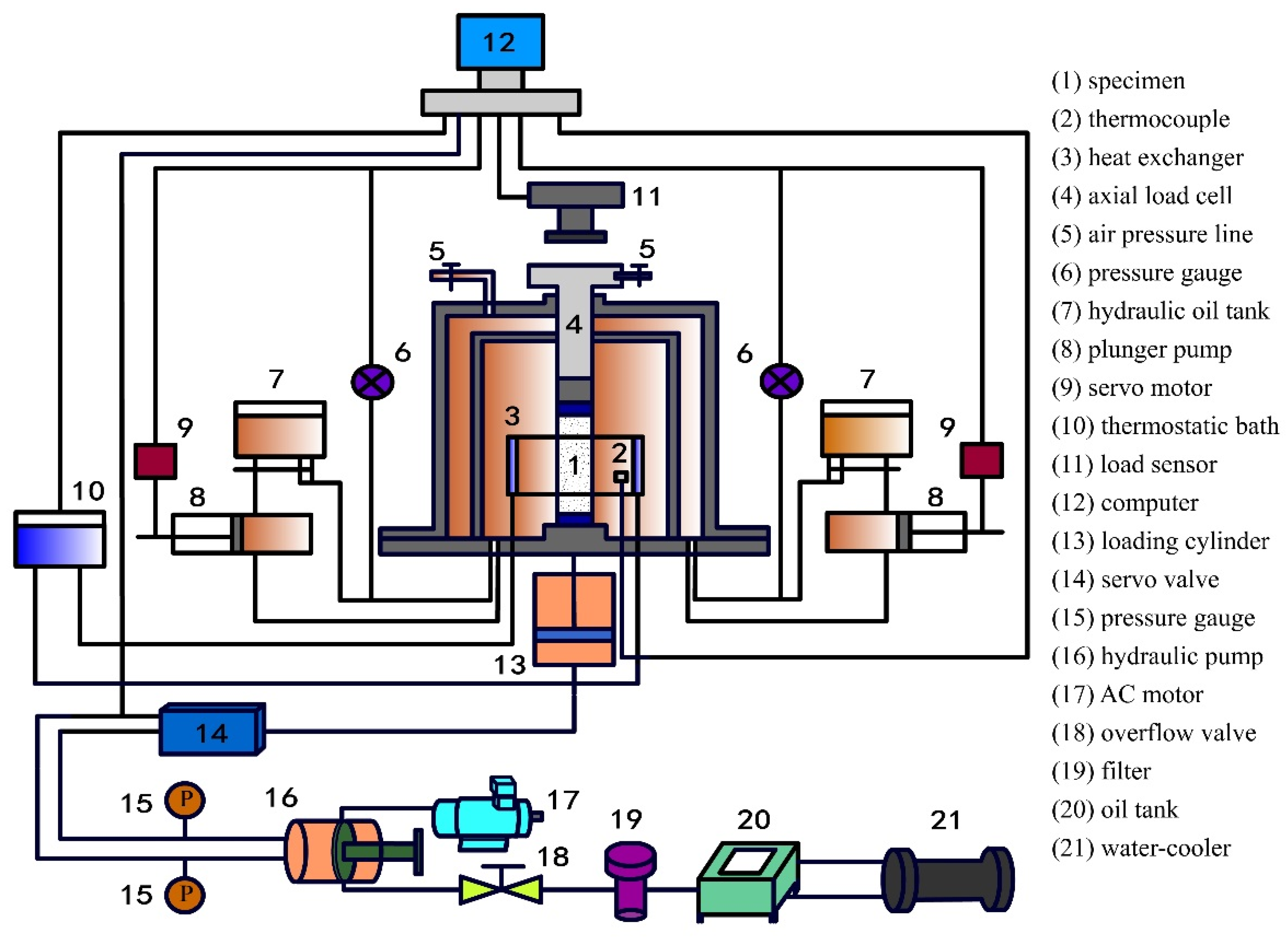
As shown in Figure 1, the natural gas hydrate triaxial apparatus that was introduced in our precious work, code-named DDW-600, was used to conduct these dynamic loading experiments of the sediments containing methane hydrates in this study [31]. Similar to the previous experimental process, sediment samples were first placed in a triaxial pressure chamber and surrounded by hydraulic fluid. Then, they were subjected to dynamic loading in the axial direction. In dynamic strength experiments, based on the MCGS testing software, a constant amplitude sinusoidal cyclic load was maintained in the axial direction until the axial deformation of sediment samples reached the failure strain [31]. Different from the dynamic strength test, in these dynamic modulus tests, the specimen was subjected to constant amplitude sine wave cyclic loads of about 10 stages under the same consolidation pressure. In the first stage of the dynamic modulus test, the pore pressure dissipated and the specimen was consolidated again after the sample vibration number reached a predetermined value, and then the dynamic modulus test moved on to the second stage, and so on until the specimen was significantly damaged. In all dynamic modulus experiments, the axial excitation frequency of each dynamic loading process was 1 Hz. In addition, all dynamic modulus experiments were performed under equal pressure consolidation and undrained conditions. Finally, based on the results of dynamic modulus experiments, the dynamic stress–strain curve and hysteresis loop of hydrate-bearing sediment samples were obtained and analyzed.
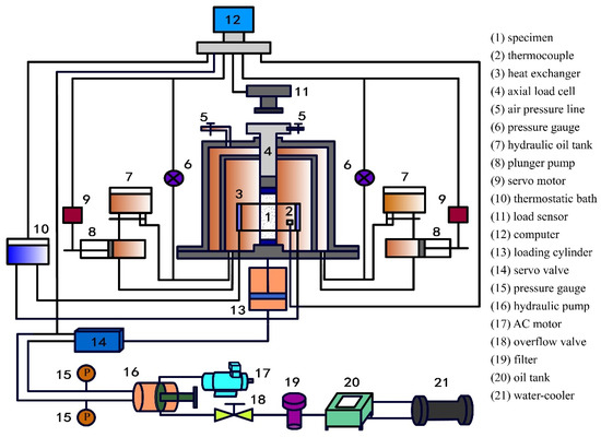
Figure 1.
The schematic diagram of the natural gas hydrate triaxial apparatus DDW-600.
2.3. Experimental Conditions
Table 1 shows the experiment conditions of these dynamic loading experiments. The porosities of hydrate-bearing sediments were 40% and 80%, and the test temperature values were −1, −3, and −5 °C. The experimental pressures were defined as the effective confining pressures, which represented the differences between confining pressures and pore pressures, and the values of experimental pressures were 0.5, 1, and 2 MPa. Each sample was subjected to dynamic loads of 8–12 stages, and the sample was vibrated 23 times under each dynamic loading.

Table 1.
Experimental conditions of the dynamic modulus experiments.
3. Results and Discussions
3.1. The Relationship between Dynamic Stress and Strain
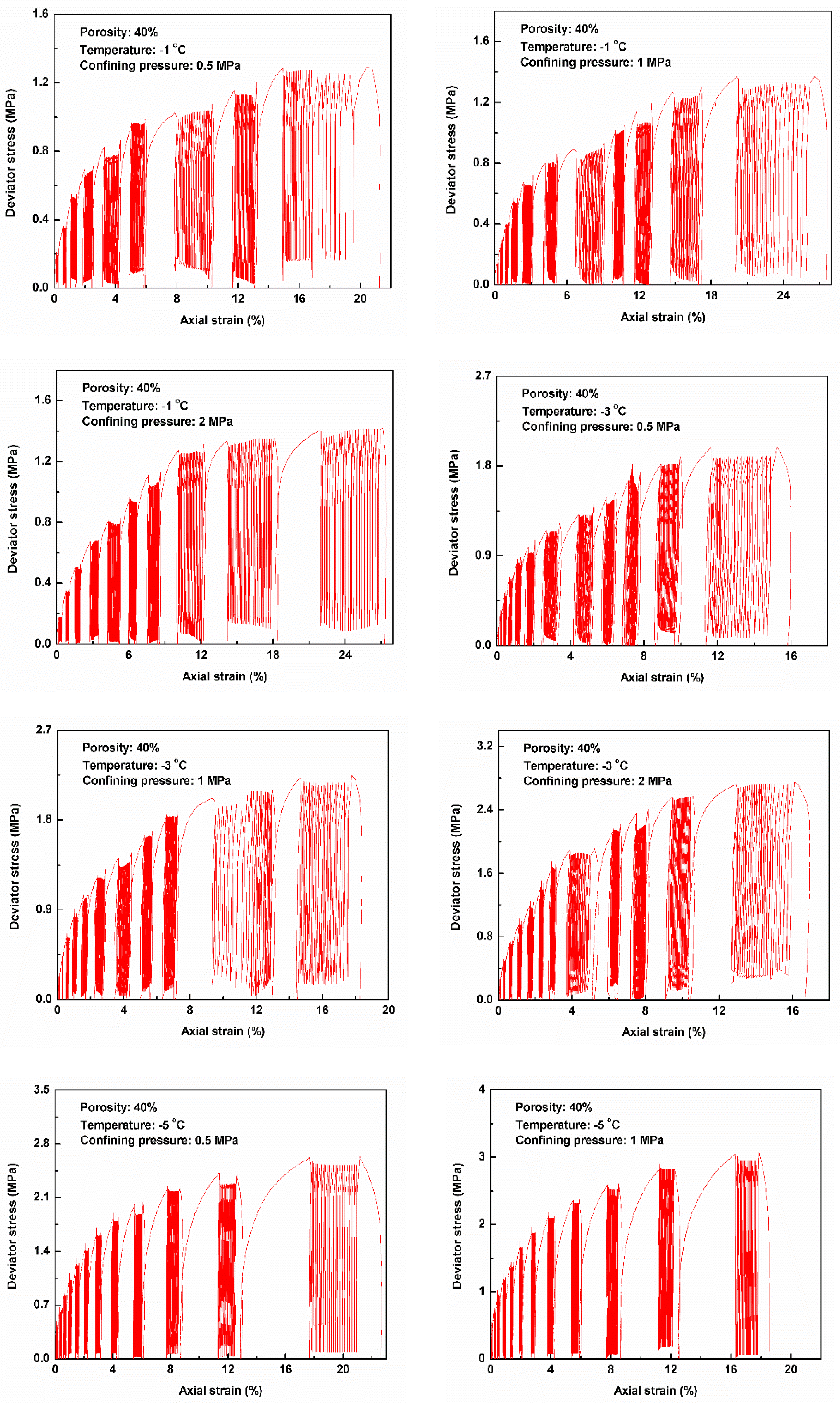
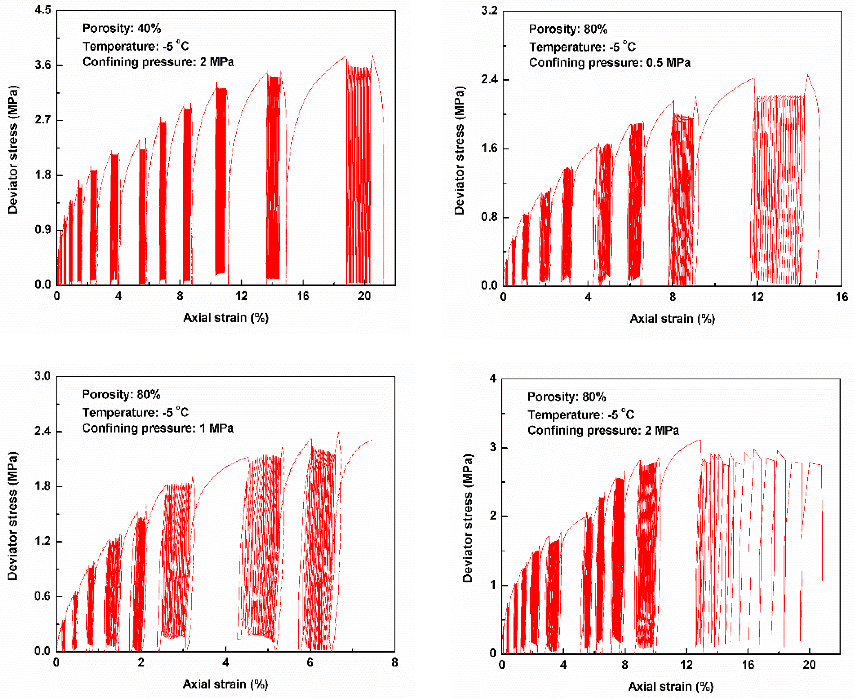
As shown in Figure 2, according to the dynamic modulus experiments, we obtained twelve dynamic stress–strain curves. For the dynamic modulus experiments of hydrate-bearing sediments, every dynamic load amplitude remained stable during each stage of the vibration experiment. Before the samples were subjected to the dynamic loading at any stage of the dynamic modulus experiment process, the stress–strain relationship was consistent with the deformation characteristics of previous static triaxial compression experiments; that is, the deformation of hydrate-bearing sediment samples still behaved with elastic-plastic characteristics [32].
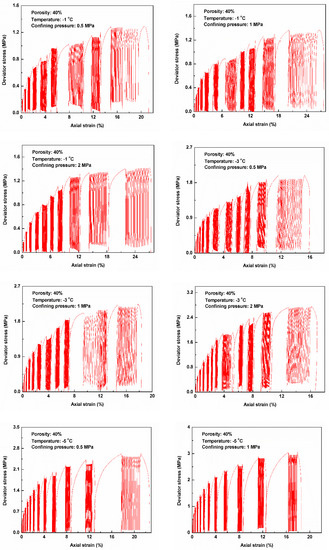
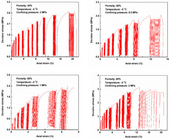
Figure 2.
Dynamic stress–strain curves of methane hydrate-bearing sediments.
The results indicate that at the early stages of dynamic modulus experiments, the hysteresis loops were not obvious on the stress–strain curves under dynamic loading; however, as the dynamic load amplitude applied to the specimen increased, several remarkable hysteresis loops were observed. Moreover, as the amplitude of dynamic loading increased, from Figure 2, it can be found that the deformation of sediment samples increased under the condition of the same number of vibrations, and shear failure occurred until the sediment sample was subjected to the dynamic loading at the final stage of the dynamic modulus experiments.
3.2. Skeleton Curves of Sediment Samples
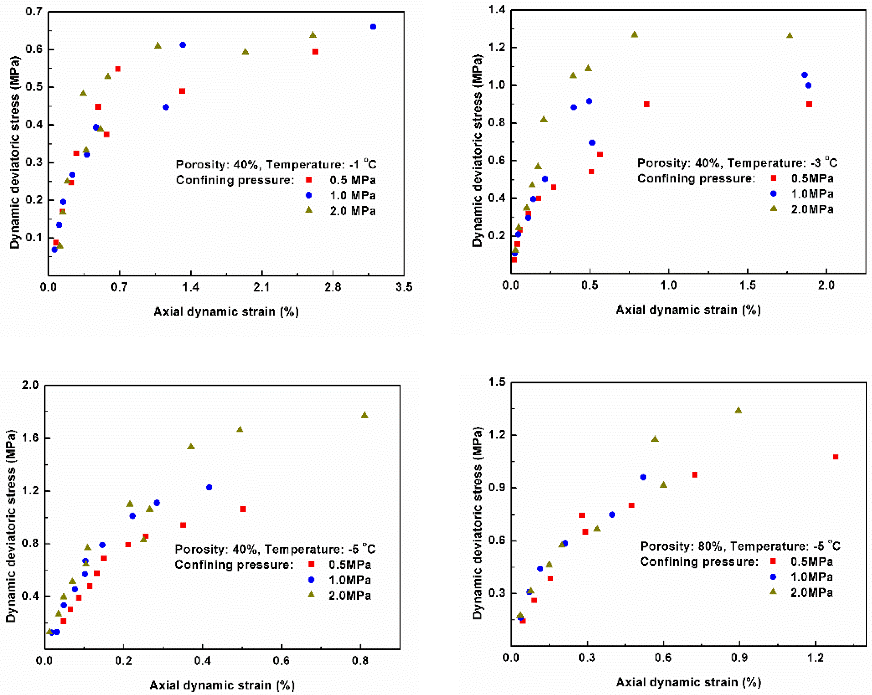
Based on the stress–strain curves under dynamic loading, the skeleton curve is defined as the envelope curve obtained by successively connecting the extremum points of each dynamic loading in the same direction (tensile or compression test). As the trajectory of the stress peak of the specimen subjected to each cyclic loading, the skeleton curve reflects the mechanical properties and deformation characteristics, such as strength, stiffness, ductility, and the capacity to resist collapse, of the samples [33,34]. According to the dynamic stress–strain curves in Figure 2, the skeleton curves of the sediments containing methane hydrates under different confining pressure conditions were drawn and analyzed, as shown in Figure 3.
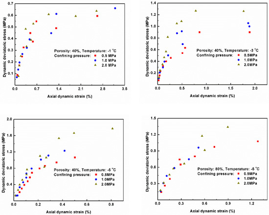
Figure 3.
The skeleton curves of hydrate-bearing sediments under different confining pressures.
From Figure 3, it is suggested that the overall trend of skeleton curves showed the same form as the stress–strain relationship of hydrate deposits obtained from static triaxial compression experiments. In the initial phase, the shear stress increased rapidly with an increase in axial strain, and the sediments’ deformation exhibited elastic properties. In the yield phase, it could be clearly found that the deformation of the sediment sample included both elastic deformation and plastic deformation. As the axial strain increased, the elastic deformation decreased gradually. With the rise of plastic deformation, the deformation of sediment samples mainly behaved with plastic properties. Under the same strain increment condition, the stress increment in the yield stage was much smaller than that in the quasi-elastic deformation stage. Finally, in the plastic deformation period, the deviator stress increased very slowly with no significant change in the slope of the stress–stain curve; that is, the specimen was still greatly deformed with an extremely small load increment.
3.3. The Maximum Dynamic Modulus of Elasticity
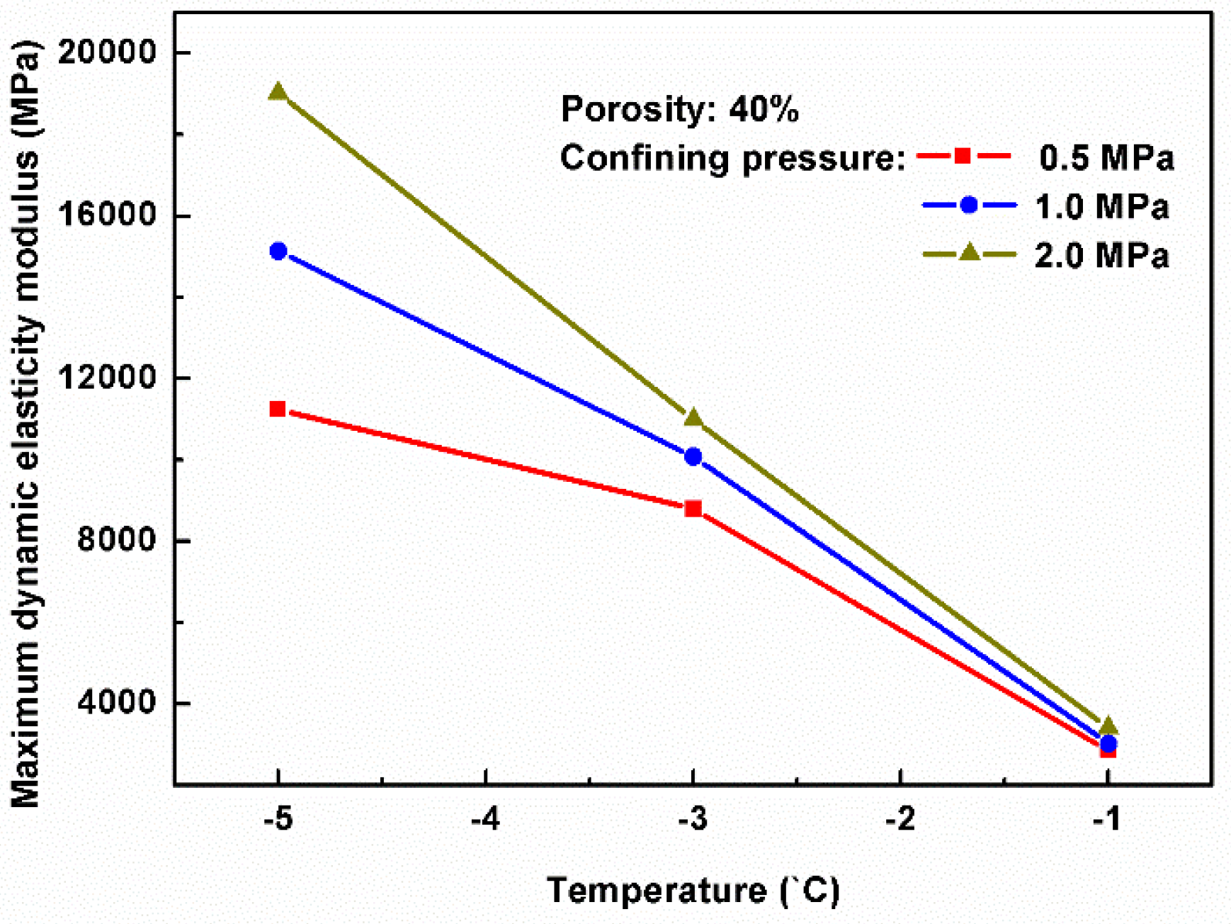
According to these stress–strain curves under dynamic loading, the dynamic elastic modulus of hydrate-bearing sediments was deduced, and the influences of confining pressures, porosities, and temperatures on these values of maximum dynamic elastic modulus were studied. As shown in Figure 4, under various confining pressure conditions, the relationships between the maximum dynamic elastic modulus and temperature were obtained. The results from Figure 4 note that the maximum dynamic elastic modulus tended to be reduced with the rise of temperature, and the decreasing trends of the dynamic elastic modulus were basically consistent with each other under various confining pressure conditions. Compared with this result at the temperature of −5 °C, the confining pressure had no significant effect on the dynamic elastic modulus at the temperature of −1 °C. To sum up, the present study indicated that temperature changes had great effects on the stiffness of hydrate-bearing sediments.
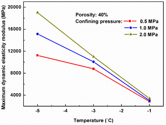
Figure 4.
Effects of temperatures on the maximum dynamic elasticity modulus under different confining pressures.
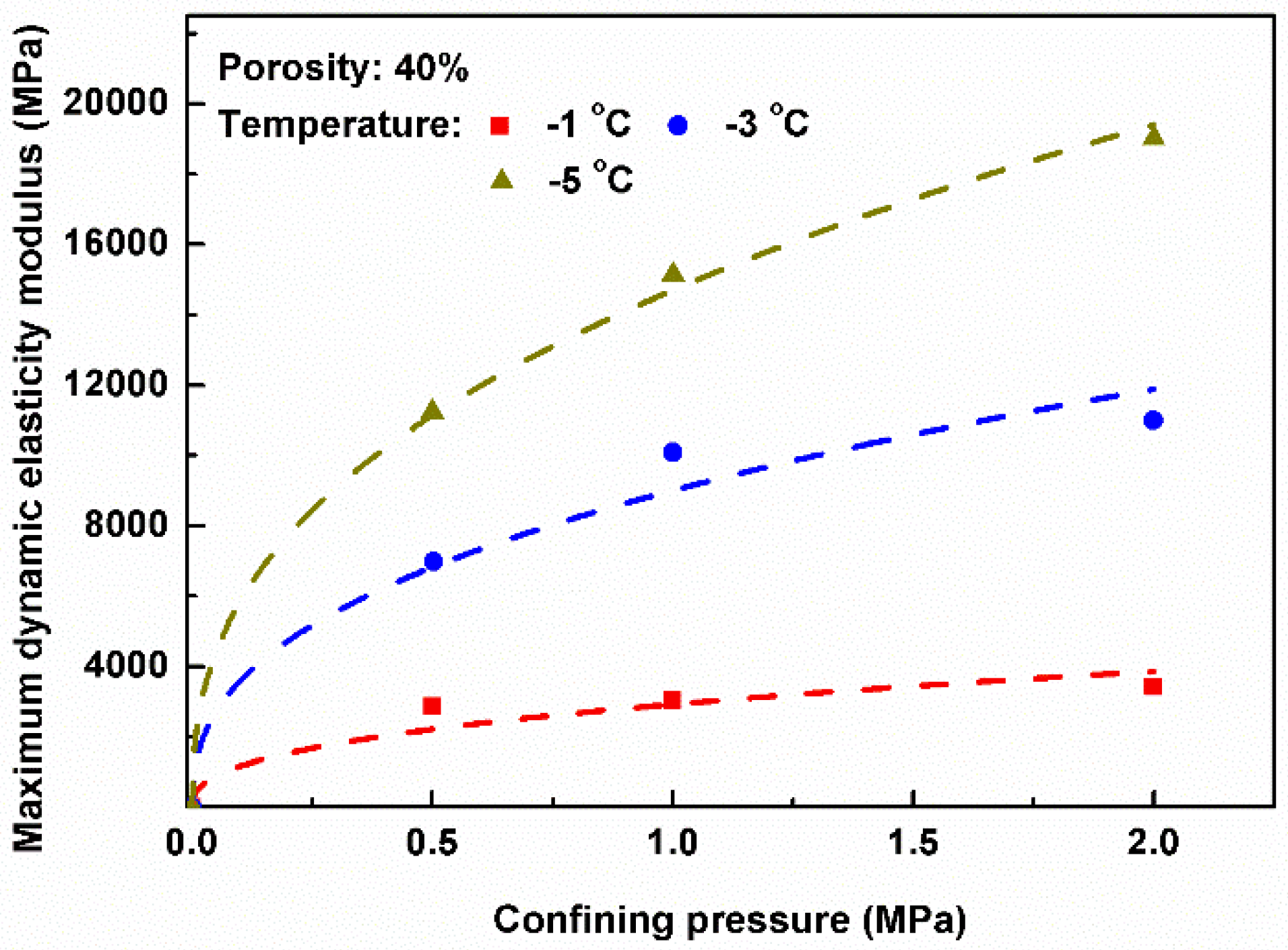
In addition, Figure 4 shows the influences of confining pressures on the maximum dynamic elastic modulus under different temperatures. The results indicate that the maximum dynamic elastic modulus of hydrate-bearing sediment tended to be enhanced as the confining pressure increased, and the lower the experimental temperature, the greater the extent of the increase in the sediment’s maximum dynamic elastic modulus was, which suggests that the effects of confining pressures on the stiffness are obvious only at lower temperature conditions. In previous studies, we noted that the values of static modulus and strength of hydrate deposits increased with the rise of confining pressure, so these variation trends of dynamic elastic modulus with confining pressures were similar to the results of static triaxial compression tests [19].
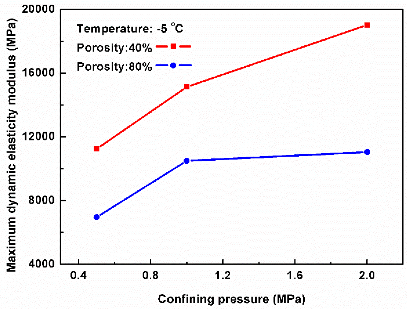
Figure 5 shows the relationships between the maximum dynamic elastic modulus and confining pressures under two conditions of porosity. The graphic results indicate that at the same confining pressure condition, the lower the porosity, the larger the dynamic elastic modulus of hydrate deposits. This might be because, as previous research noted, the strength of sediment samples largely depends on the framework structure of hydrate-bearing sediments [35]. The higher the porosity of natural gas hydrate deposits, the less the soil content within the sediments and the worse the sediment structure. Therefore, the increase in porosity had a negative effect on the sediments’ stiffness. Moreover, the results show that under the lower porosity conditions, the influences of confining pressures on the maximum dynamic elastic modulus of sediment samples were more obvious.
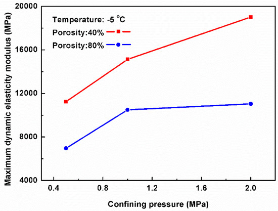
Figure 5.
Effects of confining pressures on the maximum dynamic elasticity modulus under different porosities.
3.4. Dynamic Constitutive Model
Taking into account the influences of confining pressures and temperatures on the dynamic damping ratio and dynamic elastic modulus, a dynamic constitutive model of hydrate-bearing sediments was proposed on the basis of the Hardin–Drnevich equivalent model. Considering the sediment samples as one kind of viscoelastic material, the equivalent damping ratio λ and equivalent elastic modulus E (equivalent shear modulus G) were adopted to describe the relationship between the dynamic stress and strain of hydrate deposits. The damping ratio and dynamic modulus were displayed as functions, taking dynamic strain as a variable. In addition, the influence of average consolidation pressure was also considered. By specifying the relationship between dynamic modulus E, dynamic damping ration λ, and strain amplitude, the basic problems of the equivalent viscoelastic model can be solved. Therefore, the Hardin–Drnevich equivalent model has been widely used in practical engineering because of the advantages of clear concept and convenient application [36,37].
Based on the hyperbolic form of the dynamic stress–strain skeleton curve under reciprocating load, the expression of the Hardin–Drnevich equivalent model was described as follows [38,39]:
where σd is the dynamic shear stress, σy represents the maximum dynamic shear stress, εd is the dynamic strain, and Emax represents the maximum value of dynamic elastic modulus. The expression of maximum dynamic elastic modulus function is shown in Equation (2):
where σm is the confining pressure, pa is the normal atmospheric pressure, K and n are the model parameters potentially related to temperature change. According to the experimental results of dynamic loading experiments under various temperature-pressure conditions, Figure 6 shows the influences of confining pressures on the maximum dynamic elastic modulus, and the fitted curves were also drawn. It was found that the relationship between the values of confining pressure and maximum dynamic elastic modulus satisfied the above Equation (2). By properly fitting these experimental data, the expressions of the model parameters K and n related to the value of temperature were proposed. The results indicated that the change in experimental temperature had little influence on parameter n, and it could be approximately taken as a constant.
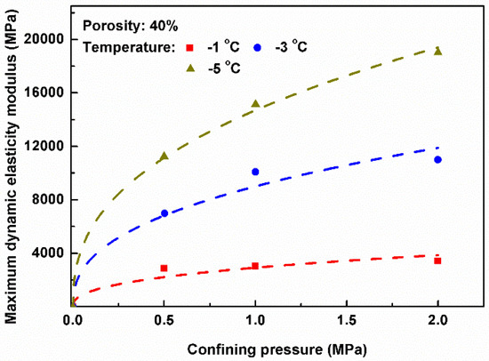
Figure 6.
The relationship between maximum dynamic elasticity modulus and confining pressure.
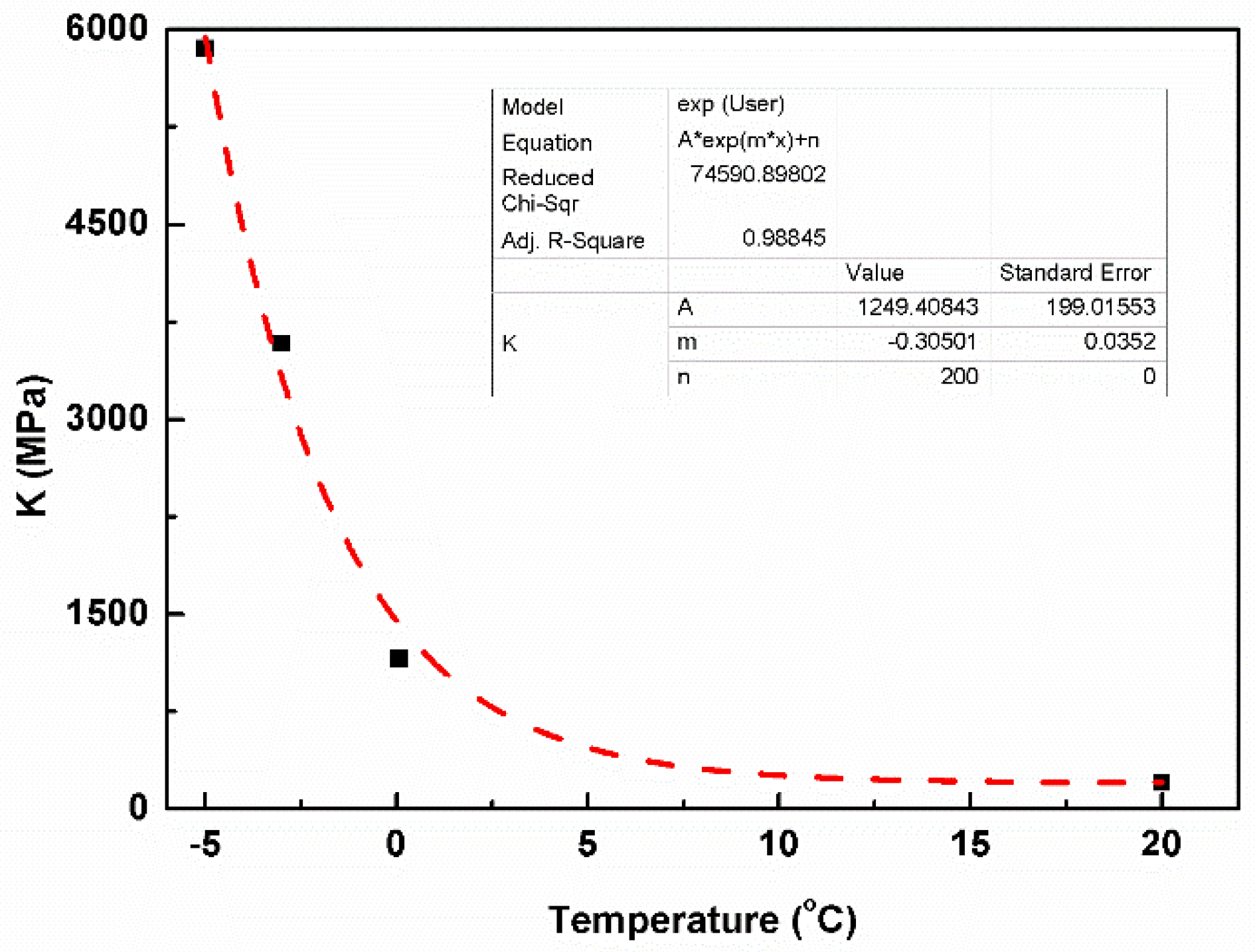
However, the effect of temperature on the parameter K was great. Figure 7 shows the relationship between parameter K and temperature, it was found that parameter K decreased exponentially as the temperature increased. The fitting equation was established as follows:
where K0 is the value of parameter K at the temperature of 20 °C, T represents the temperature, and k and a are the fitting parameters.
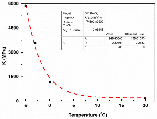
Figure 7.
The relationship between K and temperature.
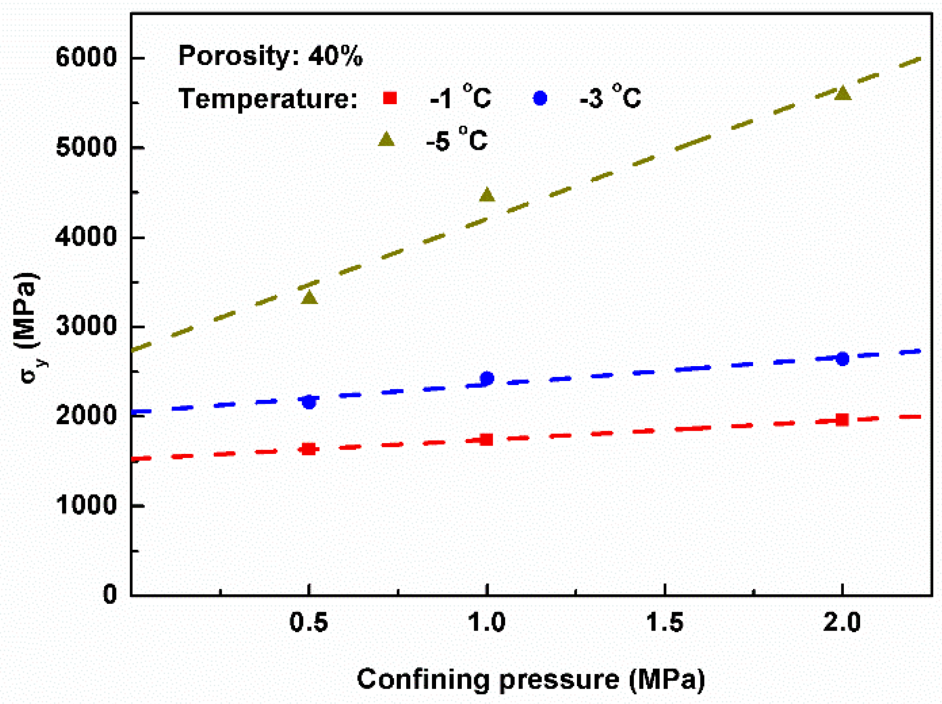
Figure 8 shows the influences of confining pressure σm on the maximum dynamic shear stress σy at different temperatures. It was suggested that there were linear relationships between the two variables, and the corresponding calculation formula was obtained as follows:
where c and M are the linear fitting parameters related to the temperature. Through data fitting, the relationship between the two fitting parameters (c and M) and temperature also satisfied the exponential variation law:
where A, u, m, and w are the fitting parameters, and c0 and M0 are the values of parameters c and m at the temperature of 20 °C.
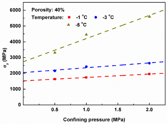
Figure 8.
The relationship between the maximum dynamic stress and confining pressure.
Based on the above Equations (2)–(7), the expressions of the maximum dynamic modulus of elasticity Emax and the maximum dynamic shear stress σy were both determined as follows:
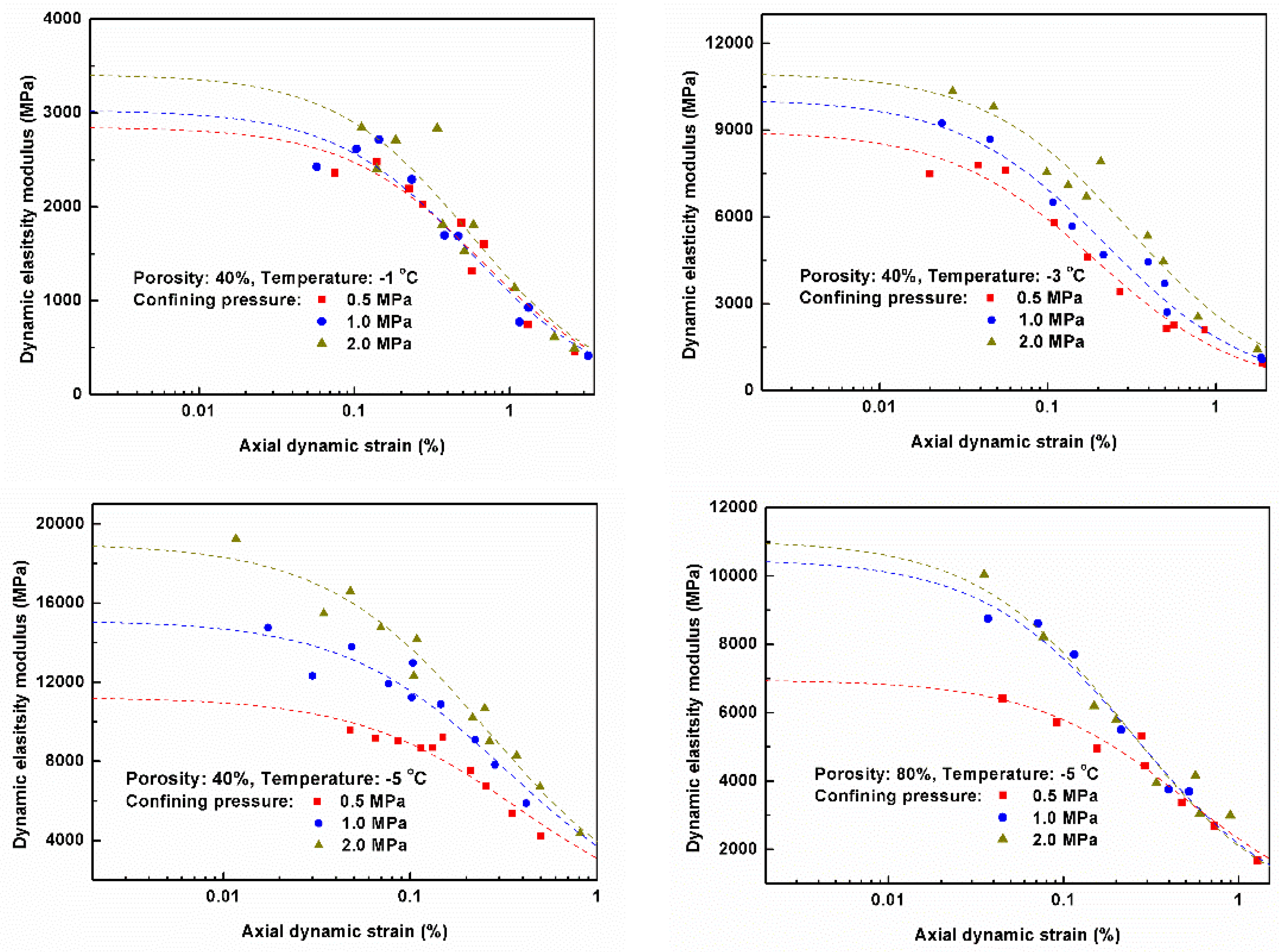
As shown in Table 2, all the model parameters are presented. Finally, based on Equations (1), (8), and (9) and Table 2, the dynamic constitutive model applied to calculate the dynamic elastic modulus of hydrate-bearing sediments was established. According to the results of dynamic loading experiments, Figure 9 shows the dynamic elastic modulus of sediments versus the axial dynamic strain, predicting the attenuation curves of dynamic elastic modulus by this constitutive model. The comparison results suggest that the simulated results are in good agreement with the experimental values, so this constitutive model has proven to be an effective tool in the process of studying the dynamic mechanical characteristics of hydrate deposits.

Table 2.
The parameters of the constitutive model.
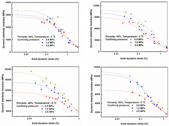
Figure 9.
Effects of dynamic strains on the dynamic elasticity modulus.
In the field of dynamic mechanical characteristics research, the soil damping ratio can be obtained under damped free vibration conditions. In most cases, it was measured in experiments of steady-state vibration under damped forced vibration conditions [40].
During the process of steady-state vibration, the work done by the external force complements the strain energy loss. Therefore, the quantity of strain energy is maintained, and there is no obvious change in the damping characteristics of soil; the hysteretic stress–strain curves conform to the approximate ellipse law [41]. According to a large amount of experimental data, Hardin et al. [39] performed a systematic analysis on the geometric characteristics of hysteretic stress–strain curves, and they derived a formula to calculate the damping ratio:
where λmax = 28-lgN, and N is the number of loading cycles. By substituting Equation (8) into Equation (10), a formula to calculate the sediments’ damping ratio was determined as follows:
4. Conclusions
By conducting several dynamic modulus experiments of hydrate-bearing sediments, on the basis of the analysis of dynamic mechanical characteristics, the following conclusions were drawn:
- With an increase in the amplitude of dynamic loading applied to the sample, the hysteresis loops became more obvious on the dynamic stress–strain curves. In this case, the sediment’s deformation increased under the condition of the same number of vibrations, and finally the samples were destroyed by the dynamic loading.
- The temperature, confining pressure, porosity, and dynamic strain had significant effects on the dynamic elastic modulus of hydrate-bearing sediments. With increasing confining pressure, the maximum dynamic elastic modulus increased exponentially. With increasing porosity and higher temperatures, the sediment’s dynamic elastic modulus was softened. In addition, under the conditions of the same porosity, temperature and confining pressure, the values of a sediment’s dynamic elastic modulus were reduced with the increase in dynamic strain.
- The characteristics of the skeleton curves of hydrate-bearing sediments showed the same form as the stress–strain relationship under static triaxial compression. Elastic deformation was the main deformation mechanism in the initial phase, and then with the development of time, plastic deformation increased and elastic deformation decreased gradually.
- Based on the Hardin–Drnevich equivalent model, and combined with the dynamic modulus properties of sediments through dynamic loading experiments, an appropriate viscoelastic constitutive model was presented. Considering the influences of temperatures and confining pressures on the model parameters E and λ, the calculation formulas of elasticity modulus and damping ratio were modified. The computational results using this model were compared with experimental values, and the comparison of the results suggested that a good agreement was achieved.
Author Contributions
Conceptualization, Y.Z.; Investigation, X.Z.; Methodology, X.Z. and Y.Z.; Writing—original draft, X.Z.; Writing—review & editing, Y.Z., Z.Y. and T.L.
Funding
This research was funded by the Natural Science Foundation of Jiangsu Province (Grant No. BK20180479), the Equipment Pre-research Fund (Grant No. 6142604180206), the Fundamental Research Funds for the Central Universities (Grant No. 30919011286), and the National Natural Science Foundation of China (Grant No. 51506092).
Acknowledgments
The authors would like to acknowledge the financial support of Natural Science Foundation of Jiangsu Province, National Natural Science Foundation of China and Nanjing University of Science and Technology. Moreover, special thanks to valuable suggestion from Dr. Xiang Sun in Dalian University of Technology, China.
Conflicts of Interest
The authors declare no conflict of interest.
References
- Kvenvolden, K.A. A review of the geochemistry of methane in natural gas hydrate. Org. Geochem. 1995, 23, 997–1008. [Google Scholar] [CrossRef]
- Schultheiss, P.J.; Holland, M.; Humphreys, G.D. Borehole pressure coring and laboratory pressure core analysis for gas hydrate investigations. In Proceedings of the Offshore Technology Conference, Houston, TX, USA, 5–8 May 2008. [Google Scholar] [CrossRef]
- Yun, T.S.; Narsilio, G.A.; Santamarina, J.C.; Ruppel, C. Instrumented pressure testing chamber for characterizing sediment cores recovered at in situ hydrostatic pressure. Mar. Geol. 2006, 229, 285–293. [Google Scholar] [CrossRef]
- Makogon, Y.F.; Holditch, S.A.; Makogon, T.Y. Natural gas-hydrates-A potential energy source for the 21st Century. J. Pet. Sci. Eng. 2007, 56, 14–31. [Google Scholar] [CrossRef]
- Yang, L.; Ai, L.; Xue, K.H.; Ling, Z.; Li, Y.H. Analyzing the effects of inhomogeneity on the permeability of porous media containing methane hydrates through pore network models combined with CT observation. Energy 2018, 163, 27–37. [Google Scholar] [CrossRef]
- Mo, J.; Wang, W.H.; Peng, N.N.; Xu, C.D.; Zhang, D.Y. New progresses on marine geological survey-research in China. Geol. Surv. China 2019, 4, 85–91. [Google Scholar]
- Stern, L.A.; Kirby, S.H.; Durham, W.B. Polycrystalline methane hydrate: Synthesis from superheated ice, and low-temperature mechanical properties. Energy Fuel 1998, 12, 201–211. [Google Scholar] [CrossRef]
- Waite, W.F.; Winters, W.J.; Mason, D. Methane hydrate formation in partially water-saturated Ottawa sand. Am. Mineral. 2004, 89, 1202–1207. [Google Scholar] [CrossRef]
- Sun, X.; Luo, H.; Luo, T.T.; Song, Y.C.; Li, Y.H. Numerical study of gas production from marine hydrate formations considering soil compression and hydrate dissociation due to depressurization. Mar. Petrol. Geol. 2019, 102, 759–774. [Google Scholar] [CrossRef]
- Li, Y.H.; Liu, W.G.; Zhu, Y.M.; Chen, Y.F.; Song, Y.C.; Li, Q.P. Mechanical behaviors of permafrost-associated methane hydrate-bearing sediments under different mining methods. Appl. Energy 2016, 162, 1627–1632. [Google Scholar] [CrossRef]
- Sun, X.; Wang, L.; Luo, H.; Song, Y.C.; Li, Y.H. Numerical modeling for the mechanical behavior of marine gas hydrate-bearing sediments during hydrate production by depressurization. J. Pet. Sci. Eng. 2019, 177, 971–982. [Google Scholar] [CrossRef]
- Li, Y.H.; Song, Y.C.; Liu, W.G.; Yu, F. Experimental research on the mechanical properties of methane hydrate-ice mixtures. Energies 2012, 5, 181–192. [Google Scholar] [CrossRef]
- Masui, A.; Haneda, H.; Ogata, Y.; Aoki, K. The Effect of Saturation Degree of Methane Hydrate on the Shear Strength of Synthetic Methane Hydrate Sediments. In Proceedings of the Fifteenth International Offshore and Polar Engineering Conference, Seoul, Korea, 19–24 June 2005. [Google Scholar]
- Masui, A.; Haneda, H.; Ogata, Y.; Aoki, K. Mechanical Properties of Sandy Sediment Containing Marine Gas Hydrates in Deep Sea Offshore Japan. In Proceedings of the Seventh ISOPE Ocean Mining Symposium, Lisbon, Portugal, 1–6 July 2007. [Google Scholar]
- Masui, A.; Miyazaki, K.; Haneda, H.; Ogata, Y.; Aoki, K. Mechanical Characteristics of Natural and Artificial Gas Hydrate Bearing Sediments. In Proceedings of the Offshore Technology Conference, Houston, TX, USA, 5–8 May 2008. [Google Scholar]
- Miyazaki, K.; Masui, A.; Tenma, N.; Ogata, Y.; Aoki, K.; Yamaguchi, T. Study on mechanical behavior for methane hydrate sediment based on constant strain-rate test and unloading-reloading test under triaxial compression. Int. J. Offshore Polar Eng. 2010, 20, 61–67. [Google Scholar]
- Miyazaki, K.; Masui, A.; Sakamoto, Y.; Aoki, K.; Tenma, N.; Yamaguchi, T. Triaxial compressive properties of artificial methane-hydrate-bearing sediment. J. Geophys. Res. 2011, 116, 49. [Google Scholar] [CrossRef]
- Hyodo, M.; Yoneda, J.; Yoshimoto, N.; Nakata, Y. Mechanical and dissociation properties of methane hydrate-bearing sand in deep seabed. Soils Found. 2013, 53, 299–314. [Google Scholar] [CrossRef]
- Song, Y.C.; Zhu, Y.M.; Liu, W.G.; Zhao, J.F.; Li, Y.H.; Chen, Y.F.; Shen, Z.T.; Lu, Y.; Ji, C.M. Experimental research on the mechanical properties of methane hydrate-bearing sediments during hydrate dissociation. Mar. Pet. Geol. 2014, 51, 70–78. [Google Scholar] [CrossRef]
- Song, Y.C.; Zhu, Y.M.; Liu, W.G.; Li, Y.H.; Lu, Y.; Shen, Z.T. The effects of methane hydrate dissociation at different temperatures on the stability of porous sediments. J. Pet. Sci. Eng. 2016, 147, 77–86. [Google Scholar] [CrossRef]
- Liu, W.G.; Zhao, J.F.; Luo, Y.; Song, Y.C.; Li, Y.H.; Yang, M.J.; Zhang, Y.; Liu, Y.; Wang, D.Y. Experimental measurements of mechanical properties of carbon dioxide hydrate-bearing sediments. Mar. Petrol. Geol. 2013, 46, 201–209. [Google Scholar] [CrossRef]
- Liu, W.G.; Luo, T.T.; Li, Y.H.; Song, Y.C.; Zhu, Y.M.; Liu, Y.; Zhao, J.F.; Wu, Z.R.; Xu, X.H. Experimental study on the mechanical properties of sediments containing CH4 and CO2 hydrate mixtures. J. Nat. Gas Sci. Eng. 2016, 32, 20–27. [Google Scholar] [CrossRef]
- Waite, W.F.; Helgerud, M.B.; Nur, A.; Pinkston, J.C.; Stern, L.A.; Kirby, S.H.; Durham, W.B. Laboratory measurements of compressional and shear wave speeds through methane hydrate. Ann. N.Y. Acad. Sci. 2000, 912, 1003–1010. [Google Scholar] [CrossRef]
- Helgerud, M.B.; Waite, W.F.; Kirby, S.H.; Nur, A. Measured temperature and pressure dependence of Vp and Vs in compacted, polycrystalline s I methane and s II methane ethane hydrate. Can. J. Phys. 2003, 81, 47–53. [Google Scholar] [CrossRef]
- Winters, W.J.; Waite, W.F.; Mason, D.; Gilbert, L.Y.; Pecher, I.A. Methane gas hydrate effect on sediment acoustic and strength properties. J. Petrol. Sci. Eng. 2007, 56, 127–135. [Google Scholar] [CrossRef]
- Yun, T.S.; Francisca, F.M.; Santamarina, J.C.; Ruppel, C. Compressional and shear wave velocities in uncemented sediment containing gas hydrate. Geophys. Res. Lett. 2005, 32, 2607. [Google Scholar] [CrossRef]
- Lee, J.Y.; Francisca, F.M.; Santamarina, J.C.; Ruppel, C. Parametric study of the physical properties of hydrate-bearing sand, silt, and clay sediments: 2. Small-strain mechanical properties. J. Geophys. Res. 2010, 115, 6670. [Google Scholar] [CrossRef]
- Priest, J.A.; Best, A.I.; Clayton, C.R.I. Attenuation of seismic waves in methane gas hydrate-bearing sand. Geophys. J. Int. 2006, 164, 149–159. [Google Scholar] [CrossRef]
- Priest, J.A.; Rees, E.V.L.; Clayton, C.R.I. Influence of gas hydrate morphology on the seismic velocities of sands. J. Geophys. Res. 2009, 114, 6284. [Google Scholar] [CrossRef]
- Hu, G.W.; Ye, Y.G.; Zhang, J.; Liu, C.L.; Li, Q. Acoustic response of gas hydrate formation in sediments from South China Sea. Mar. Petrol. Geol. 2014, 52, 1–8. [Google Scholar] [CrossRef]
- Zhu, Y.M.; Li, Y.H.; Liu, W.G.; Song, Y.C.; Luo, T.T.; Wu, Z.R. Dynamic strength characteristics of methane hydrate-bearing sediments under seismic load. J. Nat. Gas Sci. Eng. 2015, 26, 608–616. [Google Scholar] [CrossRef]
- Li, Y.H.; Song, Y.C.; Liu, W.G.; Yu, F.; Wang, R. A new strength criterion and constitutive model of gas hydrate-bearing sediments under high confining pressures. J. Petrol. Sci. Eng. 2013, 109, 45–50. [Google Scholar] [CrossRef]
- Li, X.J.; Liao, Z.P.; Zhang, K.X. A functional formula of dynamic skeleton curve taking account of damping effect. Earthq. Eng. Eng. Vib. 1994, 14, 30–35. [Google Scholar]
- Chi, S.H.; Guo, X.X.; Yang, J.; Lin, G. Small strain characteristics and threshold strain of dynamic Hardin-Drnevich model for soils. Chin. J. Geotech. Eng. 2008, 30, 243–249. [Google Scholar]
- Yu, F.; Song, Y.C.; Li, Y.H.; Liu, W.G.; Lam, W.H. Analysis of stress-strain behavior and constitutive relation of methane hydrate-bearing sediments with various porosity. Int. J. Offshore Polar Eng. 2011, 21, 316–322. [Google Scholar]
- Mitchell, J.K.; Soga, K. Fundamentals of Soil Behavior, 3rd ed.; Wiley: Hoboken, NJ, USA, 2005. [Google Scholar]
- Yin, Z.Z. Geotechnical Principle; China Water and Power Press: Beijing, China, 2007. [Google Scholar]
- Kondner, R.L. Hyperbolic stress-strain response: Cohesive soils. J. Soil Mech. Found. Div. 1963, 89, 115–144. [Google Scholar]
- Hardin, B.O.; Drnevich, V.P. Shear modulus and damping in soils: Design equations and curves. J. Soil Mech. Found. Div. 1972, 98, 667–692. [Google Scholar]
- Zhou, J.; Bai, B.; Xu, J.P. Theory and Calculation of Soil Dynamic Mechanics; China Architecture and Building Press: Beijing, China, 2001. [Google Scholar]
- Li, S.Q. Discussion on delayed curve about soil viscoelasticity model. J. Liaoning Inst. Technol. 2004, 24, 58–60. [Google Scholar]
© 2019 by the authors. Licensee MDPI, Basel, Switzerland. This article is an open access article distributed under the terms and conditions of the Creative Commons Attribution (CC BY) license (http://creativecommons.org/licenses/by/4.0/).

