1. Introduction
Brushless dc (BLDC) motors are well suited for high-power and high-speed drive systems because they present advantages such as high power density, low mass and volume, high torque and efficiency, simple control application, and low maintenance needs. These motors have been increasingly used, especially in the industrial sector [
1,
2,
3].
A BLDC motor drive consists of a closed-loop current control system, wherein the feedback current of three-phase windings can be obtained either through direct measurement with the current sensors present in each phase or through an estimation based on a single current sensor installed in a DC link. The use of current sensors, however, increases the cost, size, and complexity of a motor drive system and can cause problems stemming from reduced system reliability, such as sensor failures and three-phase current imbalances. These challenges can be addressed by sensing DC-link current from a single-shunt resistor placed in a DC link. This approach is the most inexpensive, reliable, and simple current measurement method available today. Given that the DC-link current is the same with the phase-winding current in the two-phase conduction operation of a BLDC motor, feedback control current can be obtained simply from the measured DC-link current and the switching state occurring during pulse width modulation (PWM). Current measurement methods that involve the use of DC-link single-shunt resistors have been explored and applied in many BLDC motor drive systems [
4,
5,
6,
7,
8].
Despite the benefits obtained from high-speed BLDC motors using DC-link single-shunt current measurement, certain problems are encountered as explained below from two points of view. First, a high-speed BLDC motor drive system requires a fast response and an extensive operation range, and the phase-winding resistance and inductance of the motor are very small. This results in substantial current ripples, which not only cause heat and stress in an electrical system but also give rise to mechanical vibrations and noise given the occurrence of torque ripples [
9,
10,
11,
12]. Also, the system requires a high switching frequency for precise control at high-speed operations [
13]. Second, owing to the delay time of switching and sampling, the DC-link single-shunt current measurement aimed at reducing the cost and size of the drive system cannot measure DC-link current at certain low-speed operating conditions where the modulation index (MI) is low. The reason is that the duration of the PWM ON cycle at operating time must be greater than the delay time of switching and sampling to sample the current supplied to the DC link [
14,
15,
16]. These two issues highlight the need to develop a control strategy for expanding the measurable range of DC-link single-shunt current, reducing current ripples, and improving control precision [
14,
15,
16].
These requirements can be resolved by using a suitable PWM technique because all the aforementioned considerations depend on each operating characteristic of PWM methods for BLDC motors under the same system and operating conditions. Therefore, in addition to analyzing the characteristics of each BLDC motor-intended PWM approach, developers should create a control algorithm underlain by an optimal PWM method that considers measurement performance for DC-link single-shunt current and control performance (current ripples and control precision) for high-speed operation. In a typical BLDC motor control system, only one PWM method is used regardless of the operating region [
17,
18,
19]. However, among the various PWM methods for BLDC motors, each PWM method has different advantages and disadvantages depending according to the speed region [
20,
21,
22,
23,
24,
25,
26,
27,
28]. Therefore, as shown in
Figure 1, the overall performance can be improved by using one PWM method suitable for sensing the DC-link current at low-speed and the other PWM method which can reduce the current ripple of the high-speed motor at high-speed.
Correspondingly, this research developed a hybrid PWM control method to improve the control performance of high speed operation and expand the current sensing range in a high-speed BLDC motor drive system that uses DC-link single-shunt current measurement. In this paper, the operating characteristics of most typical PWM methods for BLDC motors were analyzed, and then a PWM method suitable for high-speed operation was selected (
Section 2.1 to
Section 2.2). The measurable range of DC-link single-shunt current was mathematically analyzed using the previously analyzed PWM methods, after which a PWM technique advantageous for DC-link current measurement was chosen (
Section 2.3). On the basis of the analysis results, the proposed hybrid PWM control algorithm was established. One PWM method with a wide sensing range of DC-link single-shunt current is used at low-speed region, and the other PWM method with small current ripple is used at high-speed region (
Section 3). Finally, the algorithm put forward in this work was verified through experiments (
Section 4).
2. Analysis of High-Speed Operation and DC-Link Current Sensing via PWM Methods
2.1. PWM Methods for Three-Phase BLDC Motor Inverter Systems
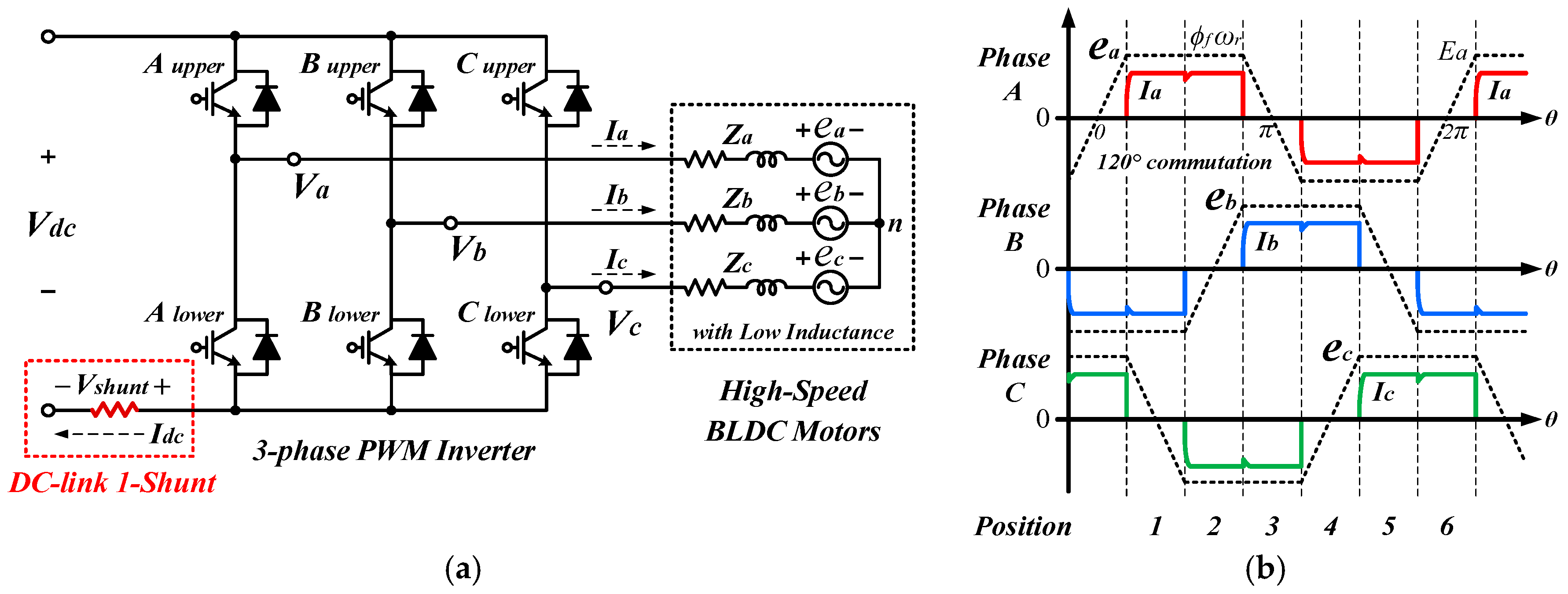
A BLDC motor with a trapezoidal back electromotive force (EMF) waveform is generally driven using a two-phase excitation method. It is operated by applying positive and negative stator currents to two-phase windings in accordance with rotor (i.e., back EMF) position. In each phase, a constant torque is generated by injecting rectangular phase currents during the 120-degree periods in which the back EMF is flat. The magnitude of the applied currents can be controlled using PWM operation. The position of the three-phase BLDC motor is divided into six sections, with a 60-degree interval implemented on the basis of signals obtained by hall effect sensors. With position signals, the phase windings of the motor are excited sequentially to produce the desired torque and speed.
Figure 2b shows the waveforms of the three-phase current and back EMF, as determined on the grounds of position. Here,
en and
In are the
n-phase back EMF and current, respectively [
17,
18,
19].
The electrical characteristics and performance of a BLDC motor drive system can vary depending on the PWM control method used. Among the six switches of an inverter, switching devices are operated for each position with reliance on a PWM technique. The PWM methods used to control BLDC motors can be categorized into two main approaches on the basis of the type of inverter output that they produce: Unipolar and bipolar methods (
Figure 3). A unipolar PWM method outputs forward voltage and 0 during conduction and freewheeling operations by activating PWM ON and OFF cycles, whereas a bipolar PWM method outputs forward voltage and reverse voltage for conduction and reverse conduction without freewheeling [
18,
19].
Note that the bipolar variant of PWM control generates twice the voltage fluctuations between PWM ON and OFF cycles. Thus, although this approach provides a fast control response, it doubles the current ripples and requires dead time for complementary switching in each phase. In particular, in a high-speed BLDC motor system where the resistance and inductance of phase windings are minimal, phase current ripples are much larger, thereby degrading control performance. Even in DC-link current measurement that uses a single-shunt resistor, the dead time used in a bipolar PWM method considerably expands the region where current sensing is impossible. For satisfactory performance, therefore, bipolar methods should not be adopted in high-speed BLDC motor drive systems that use DC-link single-shunt current measurement [
20].
2.2. Unipolar PWM Methods and Optimal PWM Method for High-Speed BLDC Motor
Table 1 summarizes the PWM waveform patterns and some operational and electrical characteristics of the most common PWM methods with unipolar outputs. These approaches are H-PWM-L-ON, H-ON-L-PWM, PWM-ON, ON-PWM, PWM-ON-PWM, and H-PWM-L-PWM (called double unipolar or modified bipolar approaches). The detailed operating characteristics and comparative performance of these PWM techniques have been explored in many studies [
21,
22,
23,
24,
25,
26,
27,
28]. These unipolar approaches, in the two active phases that should be excited positively and negatively in accordance with rotor position, can be implemented by operating the upper (positively excited phase) and lower (negatively excited phase) switches using the PWM or ON mode, respectively. Depending on PWM method, a difference occurs only in the switch position (upper or lower) and pattern sequence that use the PWM or ON mode. Accordingly, in all unipolar PWM methods, except for the H-PWM-L-PWM approach, each phase of a three-phase inverter is sequentially operated in PWM modes (an active phase, +/– excited), the ON mode (another active phase, –/+ excited), and the OPEN mode (non-excited phase) in accordance with PWM technique and rotor position. Only the H-PWM-L-PWM method is implemented by operating both active phases in the interleaved PWM mode.
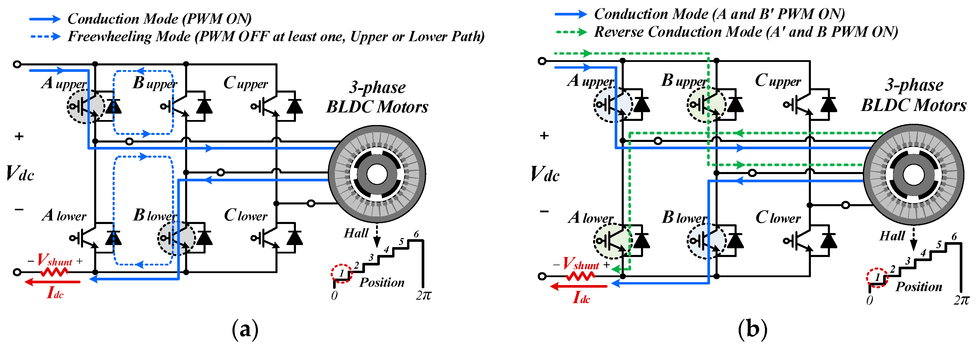
Under unipolar PWM, an inverter is operated in conduction and freewheeling modes in accordance with PWM ON and OFF operations. During the switching period, in a single position, the path of the conducting phase current for generating torque at this position is the same in all PWM approaches. The phase current flows to a DC link only in the conduction mode and can be measured by a shunt resistor. Conversely, the freewheeling operation uses the upper or lower path on the basis of the position (upper or lower) of PWM-operated switching devices, as per the PWM method adopted. In this mode, the phase current does not flow to the DC link, which makes current measurement by a single-shunt resistor impossible [
29].
Given the differences in PWM implementation, the H-PWM-L-PWM method and other unipolar approaches have varying electrical characteristics.
Figure 4 shows a detailed comparison of the PWM patterns and waveforms of the phase and DC-link currents during one switching cycle under the H-PWM-L-PWM and other unipolar techniques. The two switching patterns are the on/off signals of the top and bottom switches for each of the two excited active phases (i.e., PWM and ON modes). As shown in
Figure 4a, the other unipolar PWM methods can be implemented by operating the top switch in the positively excited phase under the PWM or ON mode and the bottom switch in the negatively excited phase under the ON or PWM mode. Which switch is operated in which mode is determined by the PWM method adopted. Accordingly, each conduction and freewheeling operation is performed once in a single PWM period, and a current ripple of the same frequency as the switching frequency is generated.
Unlike typical unipolar PWM techniques, the H-PWM-L-PWM method (
Figure 4b) involves the alternate switching of upper and lower switches using interleaved PWM signals. The switching frequency of each switch is the same as that observed in other unipolar PWM methods, but the interleaved PWM signal doubles the number of each operation in the conduction and freewheeling modes. This phenomenon generates a current ripple with twice the frequency under the same switching frequency conditions. The doubled frequency, in turn, reduces the magnitude of the current ripple under the same voltage fluctuations.
The comparative analysis showed that the H-PWM-L-PWM and other unipolar techniques have different current ripple magnitudes because of the variance in the number of conductions activated under a single switching period. Although the loss is increased due to the increase in the number of switching, the H-PWM-L-PWM–induced reduction in current ripple magnitude can narrow the current sensing range, heat generation in an inverter, mechanical vibrations, and noise. In addition to producing small current ripples, this method can double the number of current sensing instances, resulting in improved current control precision in high-speed regions. Thus, for high-speed BLDC motor drive systems with very low resistance and inductance in phase windings, the H-PWM-L-PWM approach with increasing number of conductions is very advantageous for reducing current ripples and enhancing control precision at high speeds.
2.3. PWM Method for DC-link Single-Shunt Current Sensing
In a BLDC motor inverter system that excites only two of the three phases, phase conducting current becomes the DC-link current so that motor phase current can be controlled by sensing the DC-link current under conduction operations. The DC-link current can be measured only under conduction in which conducting current flows through a DC-link shunt resistor. Such measurement cannot be implemented during freewheeling operation. As illustrated in
Figure 5a, in the DC-link single-shunt current measurement of an actual inverter system, from the generation of a PWM ON signal (under the conduction mode) up to the actual conduction operation wherein current can be sensed, a time delay occur due to the turn-on delay time of power switching devices, the settling time for stabilizing the ringing waveform of shunt voltage due to parasitic inductance and capacitor components during switching, and sampling time for the shunt voltage of an analog-to-digital converter. Accordingly, the PWM ON time determined by duty ratio and actual conduction time differs, and the accurate measurement of the DC-link current requires securing the actual conduction time minus the delay time from the PWM ON duty time. In other words, the fact that the PWM ON time is greater than the delay time enables conduction and current measurement, but current cannot be measured in the operating region where the actual conduction time is undetermined given that the PWM ON time is shorter than the delay time. This low-MI region is referred to as the unmeasurable current region (gray shaded region in
Figure 5b).
Ascertaining the scope of the operating region where measuring current in an inverter system is impossible necessitates calculating the actual conduction time. Specifically, this time is determined on the basis of the PWM duty ratio (or MI), switching frequency, and delay times, such as the on/off delay, settling, and sampling times. The actual conduction time is the value obtained by subtracting the delay time from the PWM ON time within one switching period. It can be formulated as Equation (1), where
Tconduction denotes the actual conduction time for which shunt current can be measured,
fsw represents the switching frequency,
D (0 ≤
D ≤ 1) is the PWM duty ratio,
Ndiv (1 or 2) refers to the number of conduction operations during one switching period according to the employed PWM method, and
Tdelay stands for the switching delay time. If the calculated
Tconduction is greater than 0, then current sensing is possible, but a value below 0 indicates that current sensing is impossible because of the absence of the actual conduction time.
Under the same duty ratio conditions, the actual conduction time decreases as the switching frequency and delay time increase and can be substantially reduced according to the number of conduction operations implemented through PWM methods. However, at the design and fabrication stages of the inverter system, the delay time and switching frequency are determined in advance by considering the electrical specifications of a switching device and an inverter system and the rated operating speed of a motor. From the perspective of control, therefore, these variables can be regarded as constant values. The actual conduction time then depends on the duty ratio and the number of conduction operations carried out via PWM. Other unipolar PWM techniques enable actual conduction at a duty ratio lower than that allowed by the H-PWM-L-PWM method. This difference translates to a large region, where the DC-link current can be measured.
Figure 6 shows a graph of the actual conduction time based on the PWM duty ratio for each switching frequency, as calculated using Equation (1).
Figure 6a,b show the results of the other unipolar PWM methods and the H-PWM-L-PWM approach, respectively. When a delay time of 1 μs is applied, the red shaded region where the actual conduction time is less than 0 is the area where current sensing is impossible, and the yellow shaded region is the area where current sensing is theoretically possible since the actual conduction time is greater than 0. This segment is, nevertheless, an unstable region where current sensing noise can also occur. Under the same duty ratio, an increase in switching frequency expands the region where current sensing is impossible. Under the same switching frequency conditions, the current sensing range determined on the basis of the PWM method employed differs because of variances in the number of conduction operations activated under the various PWM approaches. The other unipolar PWM methods exhibit a wider sensing range than that generated by the H-PWM-L-PWM technique.
In the case of a high-speed motor drive system, improving control precision generally requires operating an inverter at a high switching frequency, so that differences in unmeasurable current regions among PWM methods become even larger. For example, in a high-speed motor system with a rated speed of 96,000 rpm, a switching frequency of 40 kHz is required for 25 switching operations at the fundamental frequency of the rated speed. At 40 kHz, the H-PWM-L-PWM method and the other unipolar PWM techniques can sense current from duty ratios of 0.08 and 0.04, respectively. Therefore, the use of the other unipolar PWM methods in such a system is very advantageous for DC-link single-shunt current measurement.
3. Proposed Hybrid PWM Control Method
As recounted in
Section 2.1, the operation and electrical characteristics of PWM methods for BLDC motors were analyzed on the basis of current ripple and control precision for high-speed BLDC motors and current measurement using a DC-link single-shunt (
Section 2.2 and
Section 2.3, respectively). The results confirmed that the H-PWM-L-PWM method is suitable for reducing current ripples and improving control precision but that the other unipolar PWM approaches are appropriate for increasing the range of DC-link current sensing. In consideration of these issues, this work developed a hybrid PWM control algorithm that essentially uses the H-PWM-L-PWM method to reduce current ripples and enhance control precision in a high-speed BLDC motor drive system. However, it also partially employs a unipolar PWM method in low-speed regions, where the duty ratio is low and DC-link current measurement is impossible.
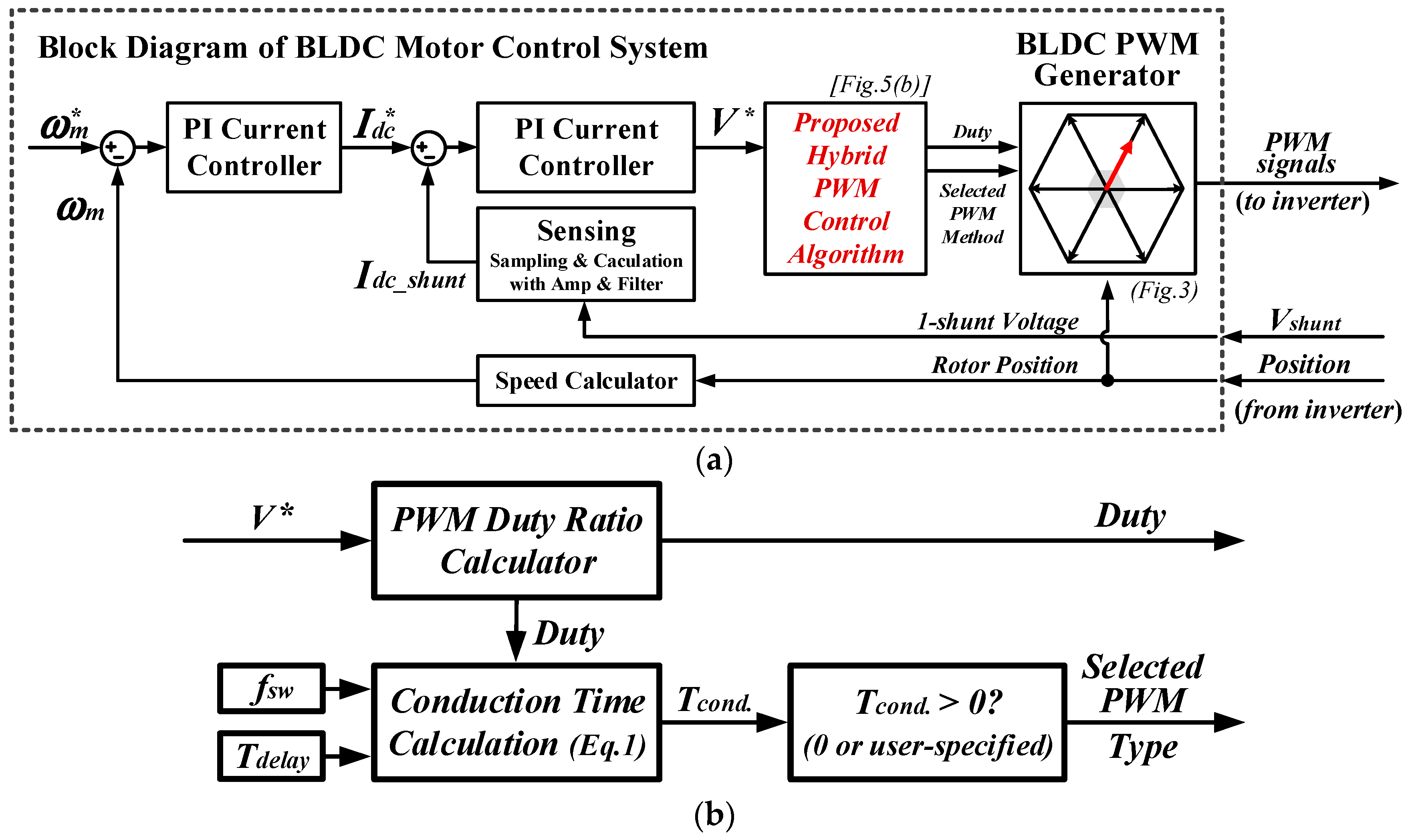
Figure 7 shows a block diagram of the BLDC motor control system with proposed hybrid PWM control algorithm.
Figure 7a shows the overall control system, and
Figure 7b shows the internal configuration of the proposed algorithm block. The loop that modulates the reference voltage output from speed and current controllers to generate PWM signals is the same as a typical BLDC motor control algorithm. An additional algorithm was developed to calculate the actual conduction time (with consideration for switching frequency and delay time) on the basis of the reference duty ratio and change the PWM method according to the calculated values. By default, the H-PWM-L-PWM method is used, but if the calculated actual conduction time is less than 0 (or a user-specified value) like at low MI, the H-PWM-L-PWM method is relinquished to make way for using of other unipolar PWM method, and when the value is greater than 0, operation switches back to the H-PWM-L-PWM approach. Since different inverter systems have different hardware circuits, parameters, and switching frequency, the user-specified value may vary.
Finally, using the proposed hybrid PWM algorithm in a high-speed BLDC motor drive system at low-speed and light-load operating regions enables the adoption of a unipolar PWM method, which increases the sensing range of DC-link single-shunt current. At high-speed and heavy-load operating regions, current ripples can be reduced and control precision can be improved using the H-PWM-L-PWM technique.
4. Experimental Results
Experiments were conducted to verify the analyzed and proposed algorithm. The experimental set-up features a 6.5 kW high-speed BLDC motor drive system. The electrical parameters used in the experiments are presented in
Figure 8.
Figure 9 illustrates the PWM patterns and actual phase current waveforms determined for the two kinds of unipolar PWM methods.
Figure 9a,b display the experimental results of the H-PWM-L-ON and H-PWM-L-PWM methods, respectively. The H-PWM-L-ON approach was used as the comparative example because all the unipolar methods, except H-PWM-L-PWM, have the same current ripple characteristics. At a switching frequency of 25 kHz and a duty ratio of 0.1, the H-PWM-L-PWM method generates about half the current ripples produced by the other unipolar methods. As with the findings discussed in
Section 2, current ripples are reduced because conduction was divided into two operations in one switching period. As the speed and load increase, the current ripples also rise. Therefore, the differences in current ripples among the PWM methods are larger than the experimental result presented in
Figure 9. The higher the speed, the greater the suitability of H-PWM-L-PWM as a means of reducing current ripples in a high-speed BLDC motor drive system with very low phase winding resistance and inductance.
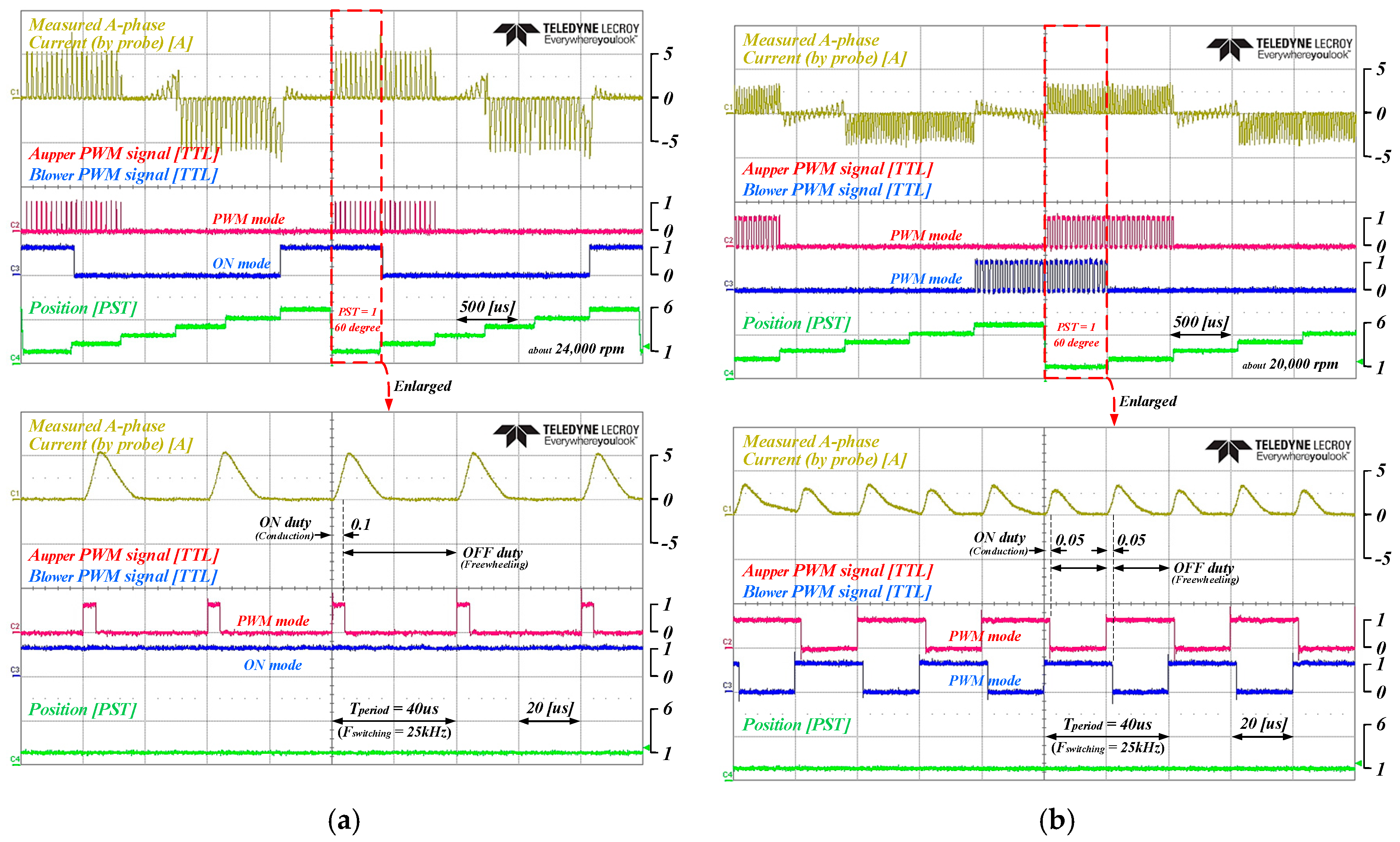
Figure 10 shows the experimental results on DC-link single-shunt current sensing via H-PWM-L-ON and H-PWM-L-PWM at duty ratios of 0.05 and 0.1, respectively.
Figure 10a,c contain the findings on the H-PWM-L-ON method, and
Figure 10b,d consist of the results on the H-PWM-L-PWM approach. Using the H-PWM-L-ON method enables the sensing of the DC-link current under both the duty ratios, but using the H-PWM-L-PWM technique prevents such sensing under duty ratios of 0.05 or less. When the duty ratio is greater than 0.05, current sensing is possible, confirming that sensing can be accurately performed under a duty ration of 0.1. For DC-link single-shunt current sensing, therefore, H-PWM-L-PWM yields a smaller measurable range than that enabled by the other unipolar PWM methods. That is, in low-MI regions, the other unipolar PWM methods are more advantageous than the H-PWM-L-PWM approach for DC-link current sensing.
Figure 11a,b show the experimental results of the motor drive system using the H-PWM-L-ON and H-PWM-L-PWM methods, respectively. The waveforms in each figure represent the actual A-phase current, DC-link 1-shunt sensing current, injected voltage and motor speed. The motor speed and the phase current increase as the applied voltage gradually rises. As it is seen from the waveforms in
Figure 11, the two PWM methods have different performance. When the H-PWM-L-ON method is used, the wide range DC link single-shunt current sensing capability results a relatively better sensing performance even in the low speed region except a small measurement noise during startup as shown in
Figure 11a. However, it can be seen that as the applied voltage and speed increase, the current ripple increases very much. On the other hand, when the H-PWM-L-PWM method is used, the current ripple is greatly reduced, but current sensing performance is degraded at low speed as shown in
Figure 11b. This happens because the area where the DC-link single-shunt current measurement is impossible is wide (up to approximately 9000 rpm in this BLDC inverter system).
The range of these regions where these current measurements are impossible or unstable depend on the hardware configuration and parameters of the inverter system. For example, there are differences in electrical characteristics such as parasitic components of shunt resistors used, rigging due to sensing input circuits, and turn-on characteristics of switching devices, etc. These change the delay time, the settling time, and the time for which the shunt voltage can be measured reliably. So, the range of impossible or unstable regions should be checked experimentally in advance in the inverter system to be used. However, this paper highlights that the region changes according to the PWM method under the same inverter system conditions.
Finally,
Figure 12 shows the experimental results of the proposed hybrid PWM control algorithm. In a low-MI operating region, where DC-link current sensing via H-PWM-L-PWM is impossible, another unipolar PWM method was used to expand the DC-link current sensing range. In the operating range above the reference value determined by calculation, the H-PWM-L-PWM method was employed to reduce current ripples. Depending on motor and inverter system, the PWM method can be changed at a user-specified reference point. The motor speed increases as the reference voltage gradually rises (
Figure 12). From the start of operation to a specific point along the process, it is operated using the H-PWM-L-ON method. Despite a large current ripple, sensing the DC-link current is possible. Beyond a specified operation point, the current ripple is reduced by switching to the H-PWM-L-PWM method. Based on the experimental results in
Figure 11, the specific point was set at 0.125 MI and the speed about 12,000 rpm.


