Geothermal Power Production from Abandoned Oil Reservoirs Using In Situ Combustion Technology

Abstract
:1. Introduction
2. Model Description of In Situ Combustion
3. Model Description of Geothermal Well
3.1. Governing Equations
3.2. Initial Conditions
3.3. Boundary Conditions
4. Results and Discussion
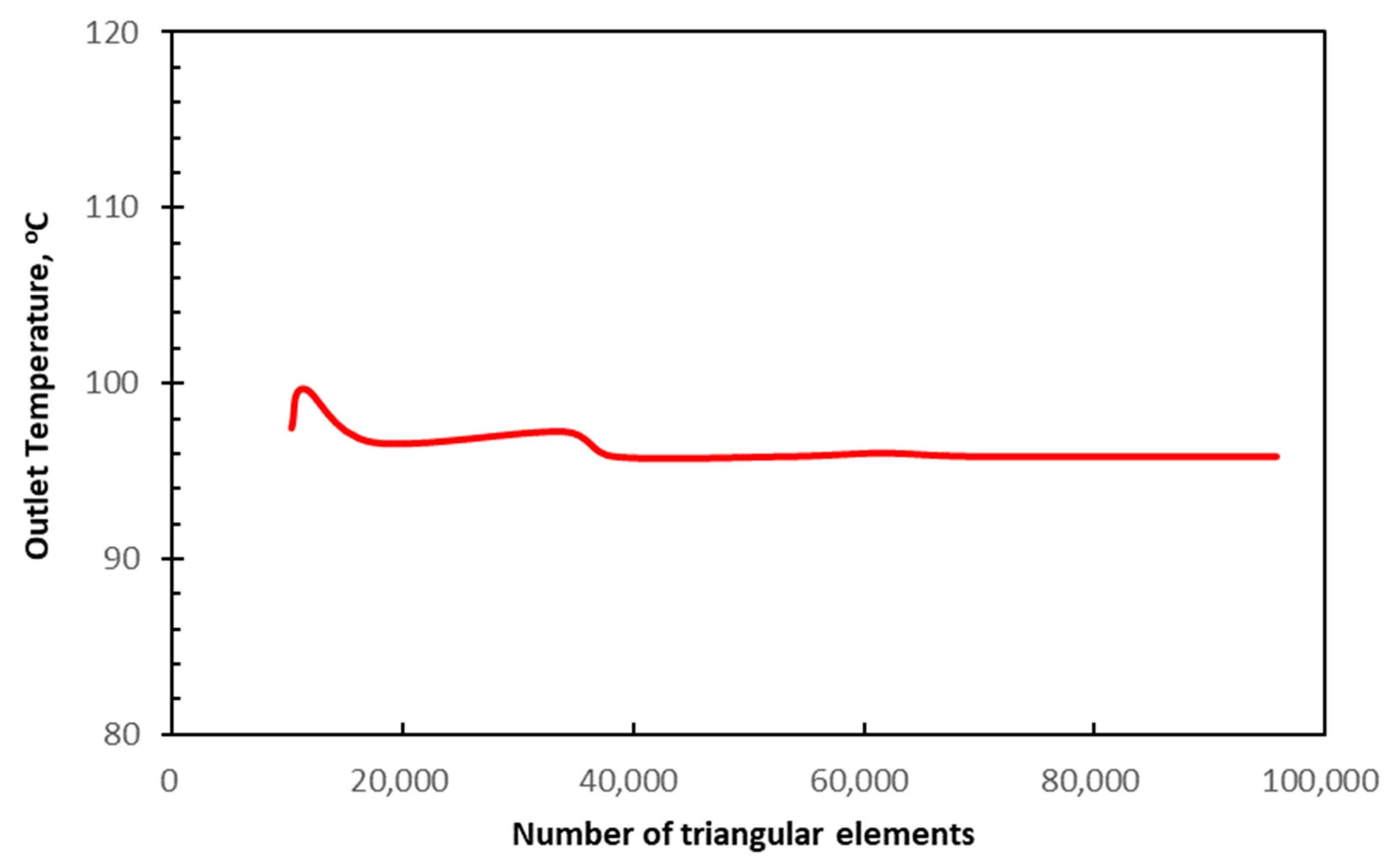
4.1. Mesh Independence Study
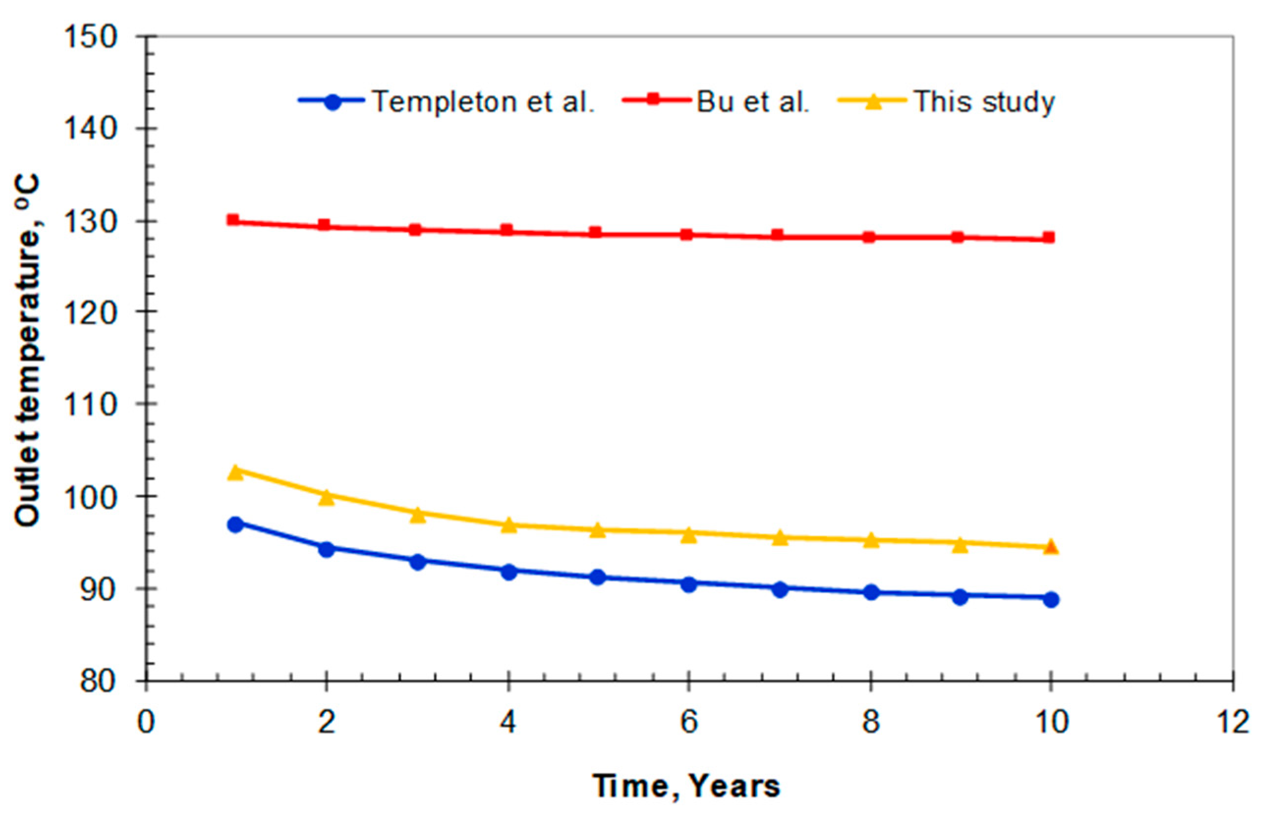
4.2. Validation and Comparison of the Model
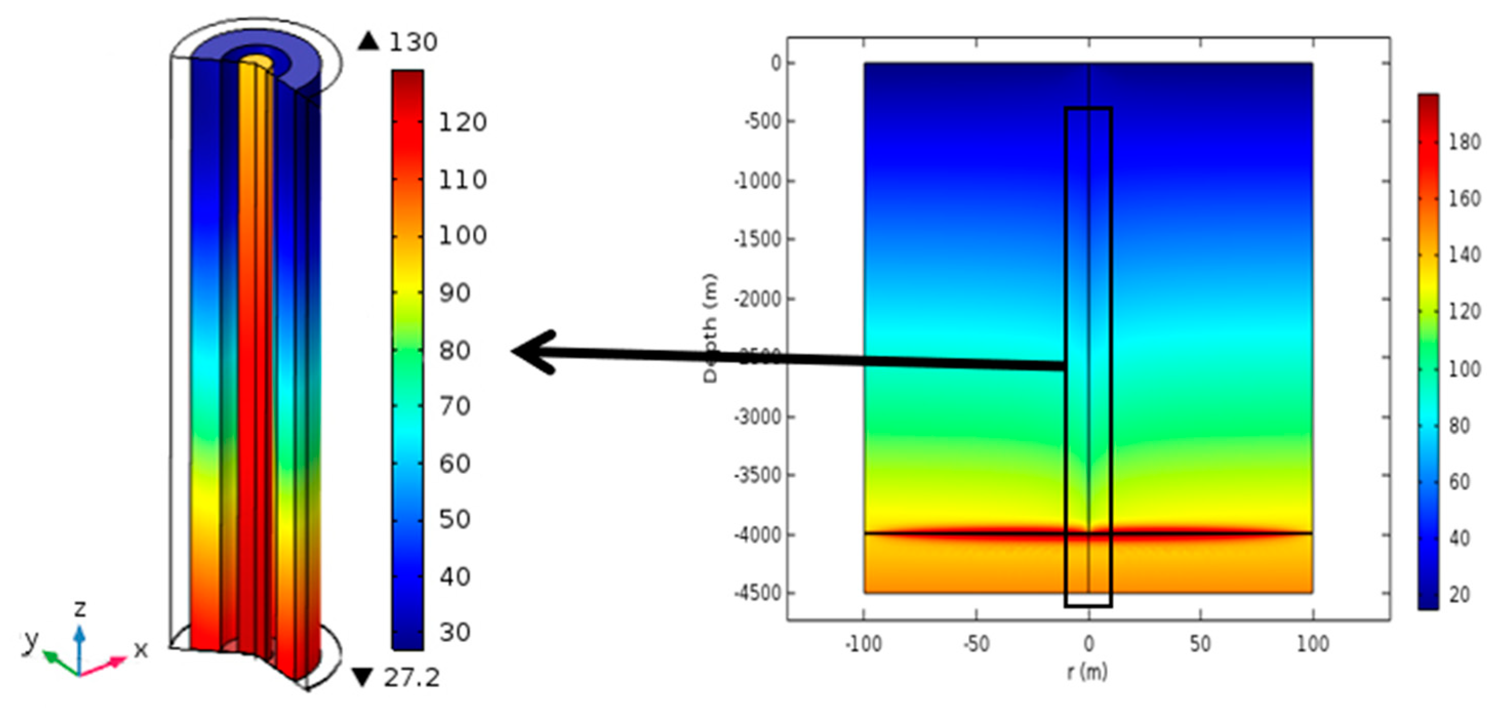
4.3. Analysis of Heat Transfer Characteristics
4.4. Heat Production Analysis
4.5. Economic Appraisal
4.6. Discussion
5. Conclusions
- (1)
- An efficient numerical model describing the retrofitting of abandoned wells into geothermal wells with in situ combustion for the purpose of recovering geothermal energy is proposed. The reliability of the model was verified and compared with two other numerical models proposed by Bu et al. [8] and Templeton et al. [29]. The current coupling strategy of the geothermal model is a simple approach for coupling the in situ combustion model and the heat exchanger model.
- (2)
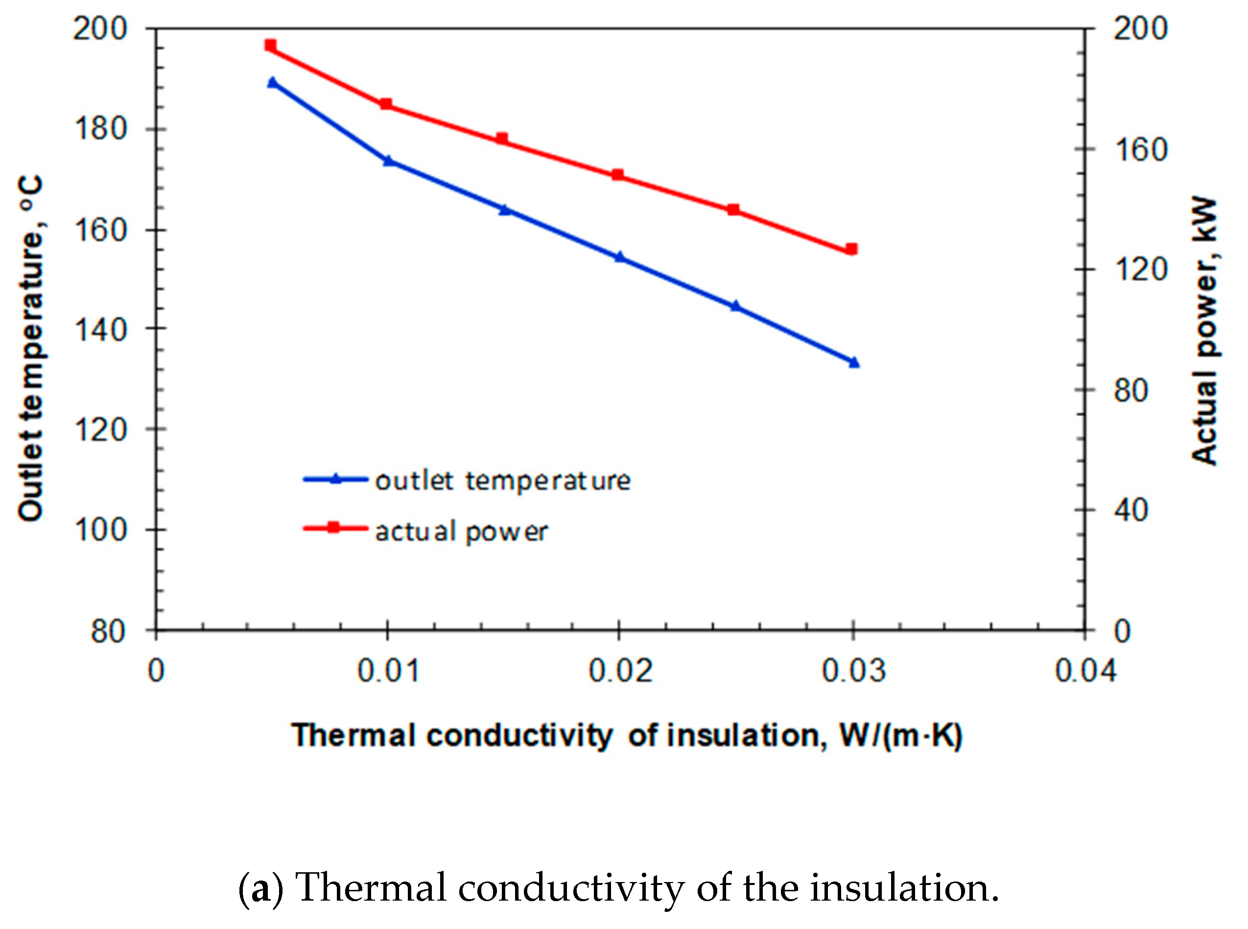
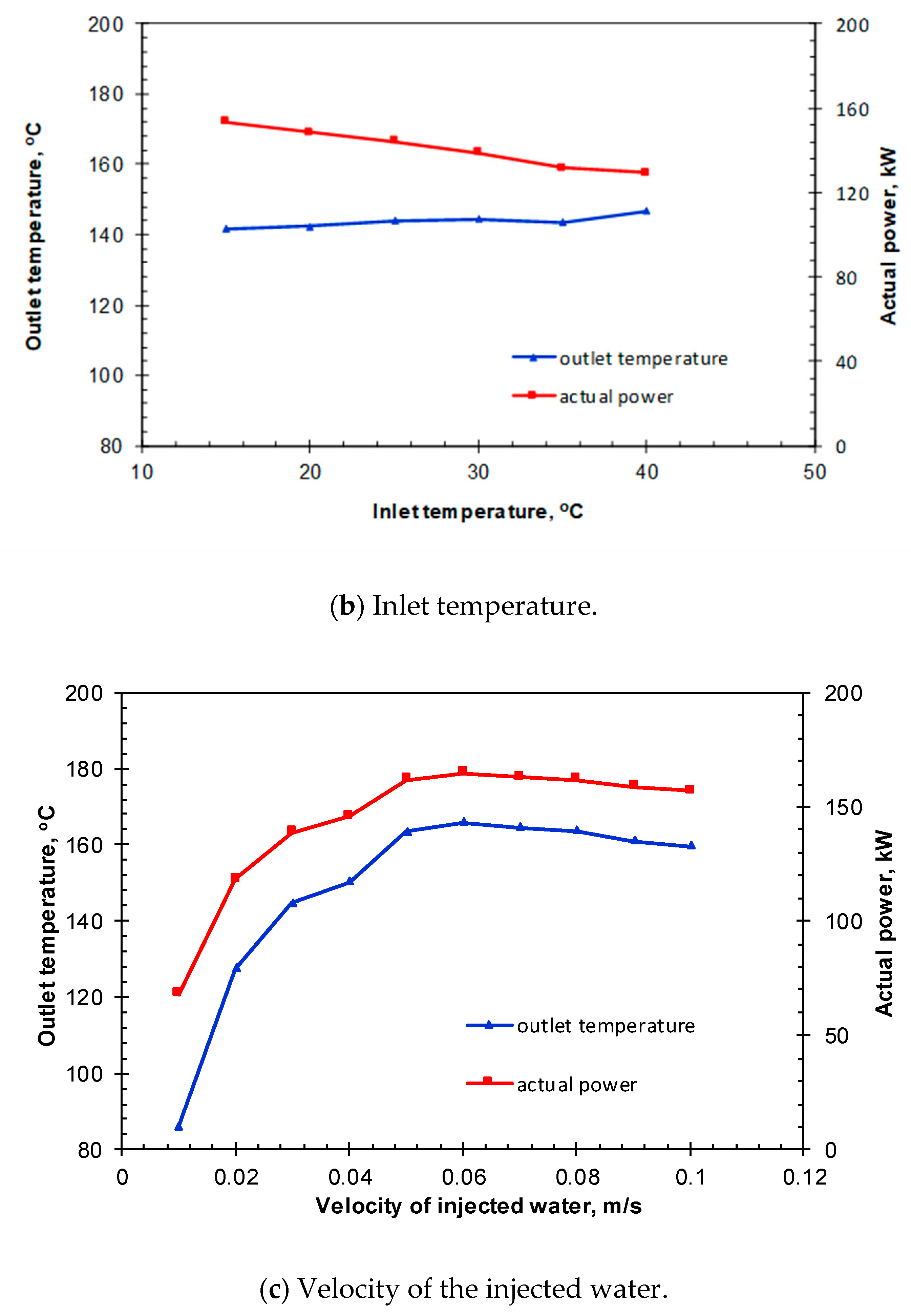
- Several parameters known to affect the system performance were modeled and analyzed using the proposed model in this study. Under specific conditions, the injection velocity has an optimal value of 0.06 m/s. Extreme values (either big or small) of the injection velocity will decrease the efficiency of the heat transfer from the surrounding rocks to the heat exchange system.
- (3)
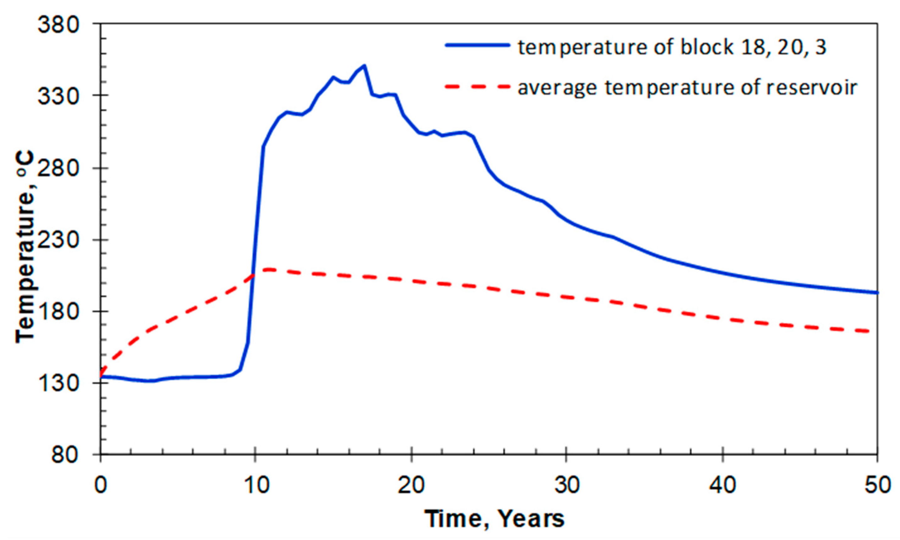
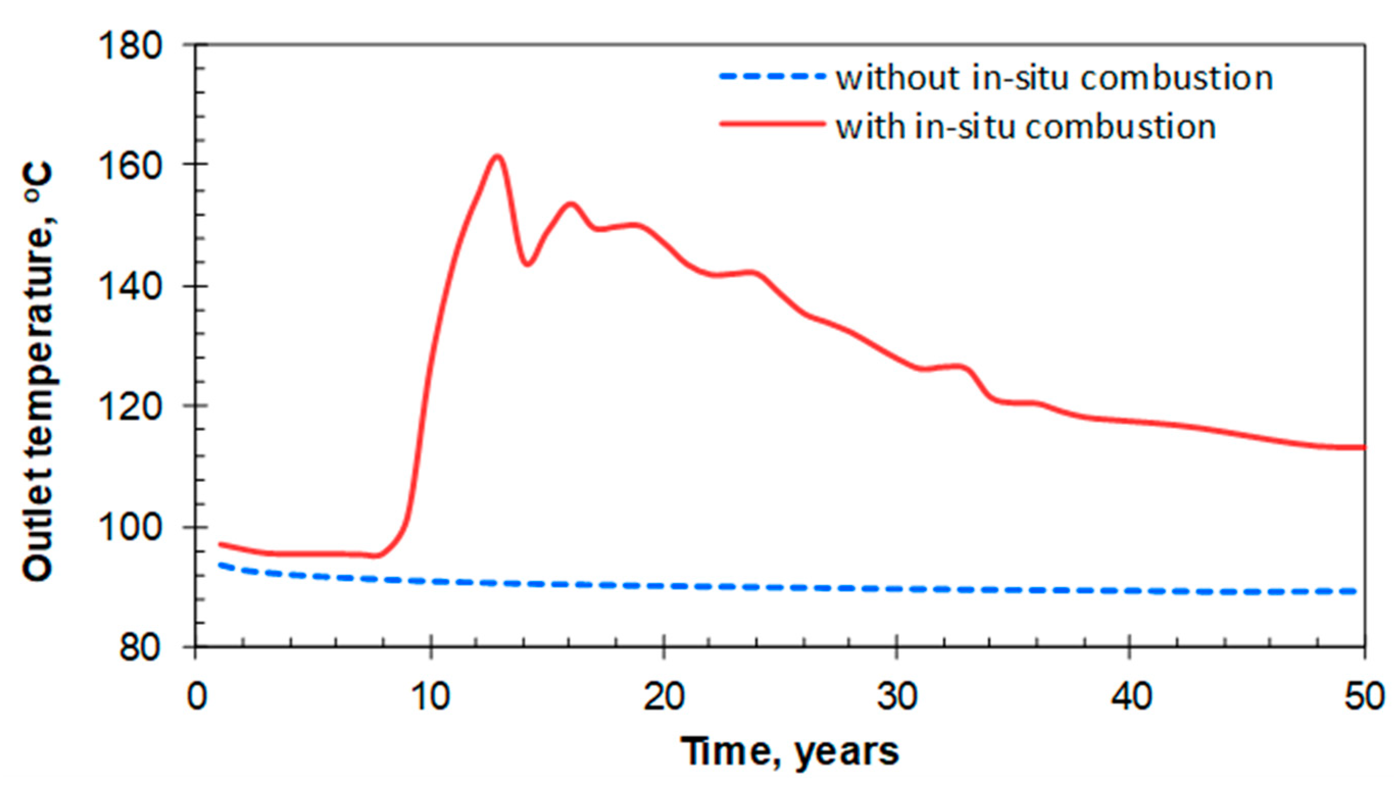
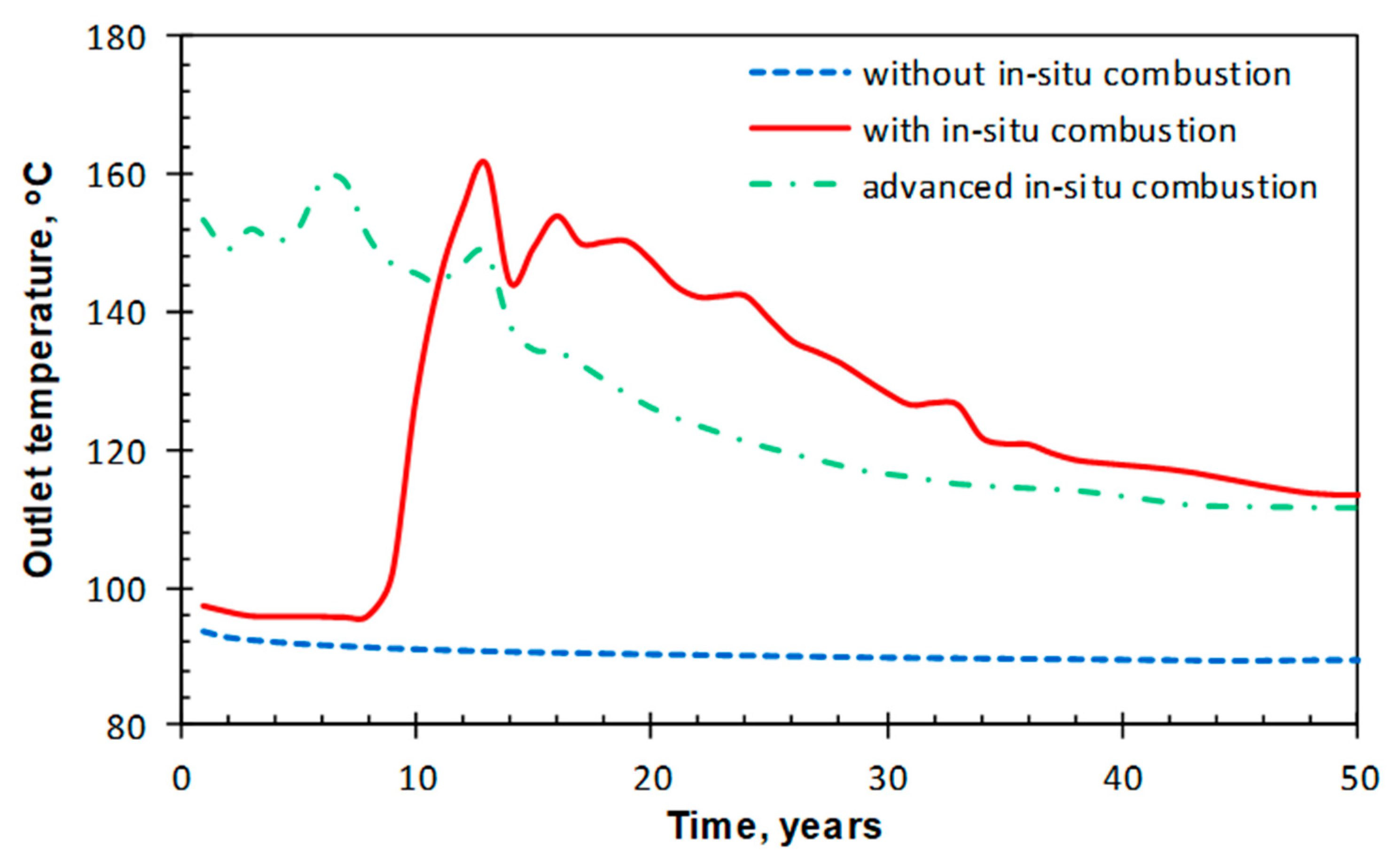
- The scenarios considered in this study demonstrated that with the help of in situ combustion, the outlet temperature increases remarkably after the combustion front reaches the area near the heat exchange wellbore, which is about 150 °C. The cumulative electricity of the scenarios with in situ combustion and advanced in situ combustion after a period of 50 years of operation are 50.3 × 10⁶ kW·h and 51.4 × 10⁶ kW·h, respectively.
- (4)
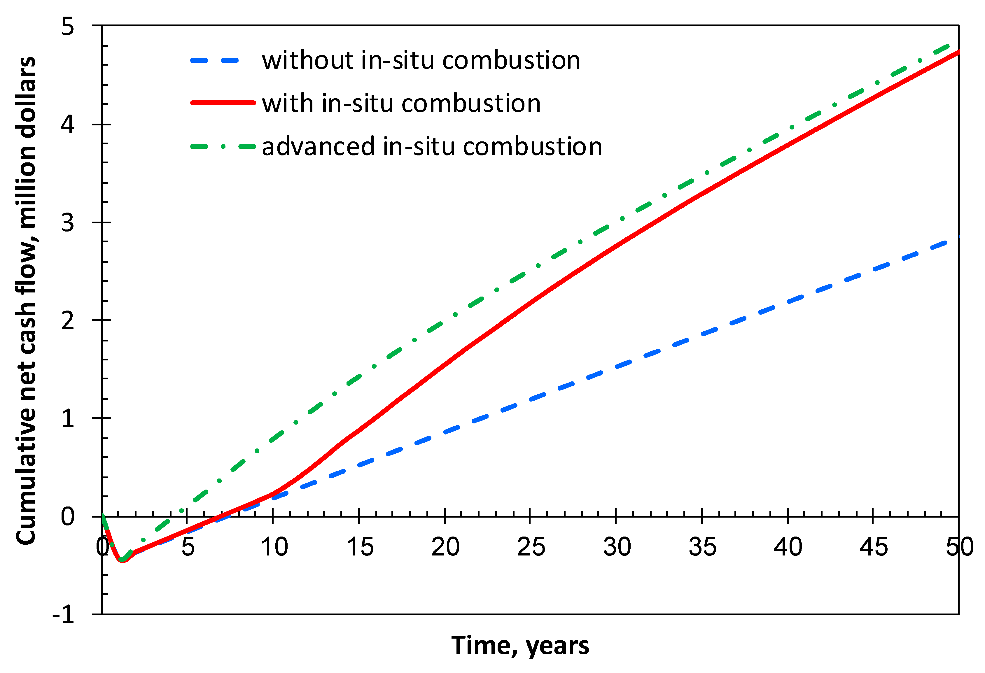
- A geothermal system using advanced in situ combustion is proposed to extract more heat from the formation right from the beginning, thereby significantly shortening the payback period of the upfront costs. For this study, the system provides the shortest payback period of 4.5 years and a final cumulative NCF of $4.94 million.
Author Contributions
Funding
Conflicts of Interest
Nomenclature
| Cp | specific heat capacity of water, J/(kg·K) |
| Cp | specific heat capacity of working fluid, J/(kg·K) |
| G | geothermal gradient, K/m |
| k | thermal conductivity, W/(m·K) |
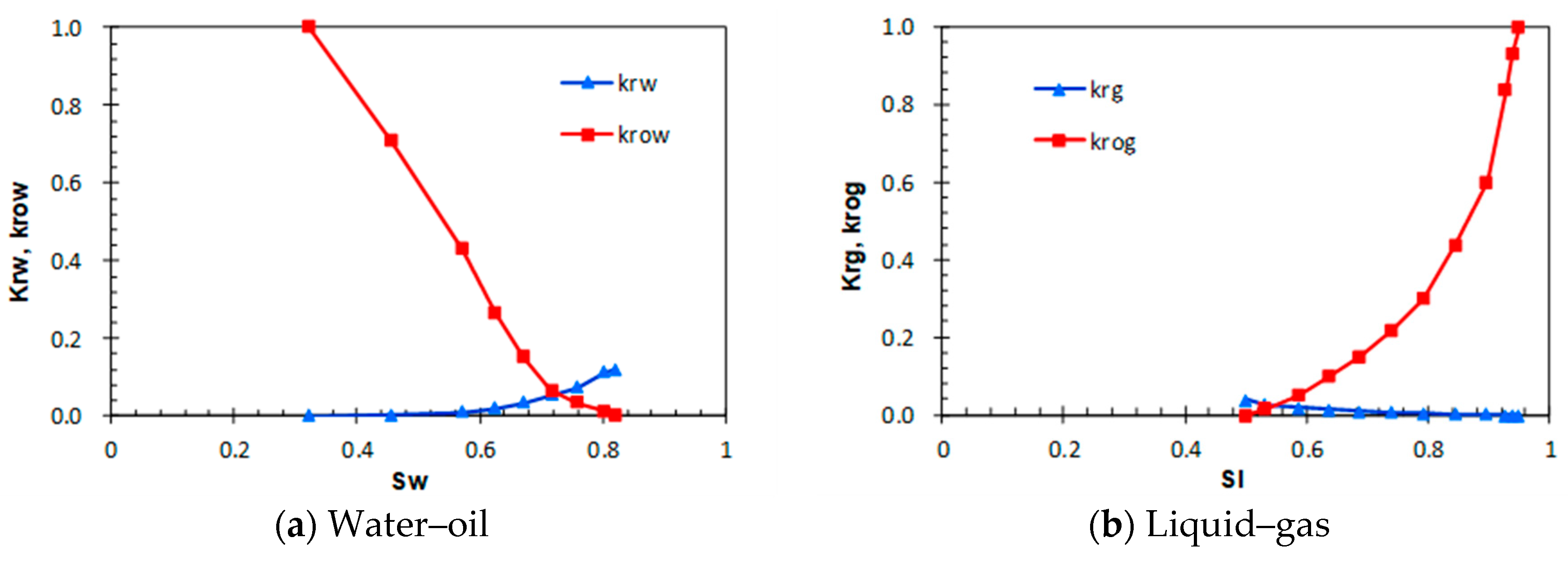
| kog | relative permeability of liquid phase |
| krg | relative permeability of gas phase |
| krow | relative permeability of oil |
| krw | relative permeability of water |
| M | mass flow rate, kg/s |
| P | actual generated power, kW |
| heat flux by conduction, W/m2 | |
| r | radial distance from the central axis, m |
| R | distance at constant temperature boundary in r direction, m |
| t | time, s |
| T | absolute temperature, K |
| Tic | temperature of reservoir with in situ combustion, K |
| Tin | inlet temperature of injection annulus, K |
| Tout | outlet temperature of extraction well, K |
| TR,0 | initial rock temperature, K |
| TR,b | rock temperature at constant temperature boundary, K |
| Tsrf | temperature at surface, K |
| velocity vector, m/s | |
| z | vertical distance from surface, m |
| Z | distance at constant temperature boundary in z direction, m |
| ηg | generator efficiency |
| ηm | mechanical efficiency of steam turbine |
| ηri | relative internal efficiency of steam turbine, |
| ρ | density of working fluid, kg/m3 |
References
- Kotler, S. Abandoned Oil and gas Wells Are Leaking. Available online: https://zcomm.org/zmagazine/abandoned-oil-and-gas-wells-are-leaking-by-steven-kotler (accessed on 5 June 2019).
- Li, T.; Zhu, J.; Xin, S.; Zhang, W. A novel geothermal system combined power generation, gathering heat tracing, heating/domestic hot water and oil recovery in an oilfield. Geothermics 2014, 51, 388–396. [Google Scholar] [CrossRef]
- Zhang, Y.J.; Li, Z.W.; Guo, L.L.; Gao, P.; Jin, X.P.; Xu, T.F. Electricity generation from enhanced geothermal systems by oilfield produced water circulating through reservoir stimulated by staged fracturing technology for horizontal wells: A case study in Xujiaweizi area in Daqing Oilfield, China. Energy 2014, 78, 788–805. [Google Scholar] [CrossRef]
- Lingyu, Z.; Jianguo, Y.; Hongbin, L.; Kewen, L. Energy from Abandoned Oil and Gas Reservoirs. In Proceedings of the SPE Asia Pacific Oil and Gas Conference and Exhibition, Perth, Australia, 20–22 October 2008. [Google Scholar]
- Davis, A.P.; Michaelides, E.E. Geothermal power production from abandoned oil wells. Energy 2009, 37, 866–872. [Google Scholar] [CrossRef]
- Wight, N.M.; Bennett, N.S. Geothermal energy from abandoned oil and gas wells using water in combination with a closed wellbore. Appl. Therm. Eng. 2015, 89, 908–915. [Google Scholar] [CrossRef]
- Barbier, E. Geothermal energy technology and current status: An overview. Renew. Sustain. Energy Rev. 2002, 6, 3–65. [Google Scholar] [CrossRef]
- Bu, X.; Ma, W.; Li, H. Geothermal energy production utilizing abandoned oil and gas wells. Renew. Energy 2012, 41, 80–85. [Google Scholar] [CrossRef]
- Nian, Y.L.; Cheng, W.L. Insights into heat transport for thermal oil recovery. J. Pet. Sci. Eng. 2017, 151, 507–521. [Google Scholar] [CrossRef]
- Noorollahi, Y.; Pourarshad, M.; Jalilinasrabady, S.; Yousefi, H. Numerical simulation of power production from abandoned oil wells in Ahwaz oil field in southern Iran. Geothermics 2015, 55, 16–23. [Google Scholar] [CrossRef]
- Mokhtari, H.; Hadiannasab, H.; Mostafavi, M.; Ahmadibeni, A.; Shahriari, B. Determination of optimum geothermal Rankine cycle parameters utilizing coaxial heat exchanger. Energy 2016, 102, 260–275. [Google Scholar] [CrossRef]
- World Energy Council. World Energy Resources: Geothermal 2016; World Energy Council: London, UK, 2016. [Google Scholar]
- Østergaard, P.A.; Lund, H. A renewable energy system in Frederikshavn using low-temperature geothermal energy for district heating. Appl. Energy 2011, 88, 479–487. [Google Scholar] [CrossRef]
- Self, S.J.; Reddy, B.V.; Rosen, M.A. Geothermal heat pump systems: Status review and comparison with other heating options. Appl. Energy 2013, 101, 341–348. [Google Scholar] [CrossRef]
- Noorollahi, Y.; Mohammadzadeh Bina, S.; Yousefi, H. Simulation of Power Production from Dry Geothermal Well Using Down-hole Heat Exchanger in Sabalan Field, Northwest Iran. Nat. Resour. Res. 2016, 25, 227–239. [Google Scholar] [CrossRef]
- Cinar, M. Creating Enhanced Geothermal Systems in Depleted Oil Reservoirs via In Situ Combustion. In Proceedings of the Thirty-Eighth Workshop on Geothermal Reservoir Engineering, Stanford, CA, USA, 11–13 February 2013. [Google Scholar]
- Cheng, W.L.; Liu, J.; Nian, Y.L.; Wang, C.L. Enhancing geothermal power generation from abandoned oil wells with thermal reservoirs. Energy 2016, 109, 537–545. [Google Scholar] [CrossRef]
- Nian, Y.L.; Cheng, W.L. Insights into geothermal utilization of abandoned oil and gas wells. Renew. Sustain. Energy Rev. 2018, 87, 44–60. [Google Scholar] [CrossRef]
- Rabiu Ado, M.; Greaves, M.; Rigby, S.P. Dynamic Simulation of the Toe-to-Heel Air Injection Heavy Oil Recovery Process. Energy Fuels 2017, 31, 1276–1284. [Google Scholar] [CrossRef]
- Hallam, R.J.; Donnelly, J.K. Pressure-up blowdown combustion: A channeled reservoir recovery process. SPE Adv. Technol. Ser. 1993, 1, 153–158. [Google Scholar] [CrossRef]
- Kujawa, T.; Nowak, W.; Stachel, A.A. Utilization of existing deep geological wells for acquisitions of geothermal energy. Energy 2006, 31, 650–664. [Google Scholar] [CrossRef]
- Wang, L.; Li, C.; Liu, S.; Li, H.; Xu, M.; Wang, Q.; Ge, R.; Jia, C.; Wei, G. Geotemperature gradient distribution of Kuqa foreland basin, north of Tarim, China. Chin. J. Geophys. 2003, 46, 403–407. [Google Scholar] [CrossRef]
- Yuan, Y.S.; Ma, Y.S.; Hu, S.B.; Guo, T.L.; Fu, X.Y. Present-day geothermal characteristics in South China. Chin. J. Geophys. 2006, 49, 1005–1014. [Google Scholar] [CrossRef]
- Fu-you, Z. Geothermal Gradient and HeatFlow Characteristics of Nanyang Basin. Ground Water. 2016, 38, 121–122. [Google Scholar]
- Yusong, Y.; Lijun, M.; Gongcheng, Z.; Herong, Z. Some Remarks about Geothermal Gradient of Sedimentary Basins. Geol. Rev. 2009, 55, 531–535. [Google Scholar]
- Liang-Ping, X.; Ju-Ming, Z. Relationship between geothermal gradient and the relief of basement rock in north China plain. Chin. J. Geophys. 1988, 31, 146–155. [Google Scholar]
- Wenquan, T. Numerical Heat Transfer; Xi’an Jiaotong University Press: Xi’an, China, 1988. [Google Scholar]
- Bird, R.B.; Stewart, W.E.; Lightfoot, E.N. Transport Phenomena, 2nd ed.; John Wiley Sons, Inc.: Hoboken, NJ, USA, 2006. [Google Scholar]
- Templeton, J.D.; Ghoreishi-Madiseh, S.A.; Hassani, F.; Al-Khawaja, M.J. Abandoned petroleum wells as sustainable sources of geothermal energy. Energy 2014, 70, 366–373. [Google Scholar] [CrossRef]
- Dittus, F.W.; Boelter, L.M.K. Heat transfer in automobile radiators of the tubular type. Int. Commun. Heat Mass Transf. 1985, 12, 3–22. [Google Scholar] [CrossRef]
- Cheng, W.L.; Li, T.T.; Nian, Y.L.; Xie, K. Evaluation of working fluids for geothermal power generation from abandoned oil wells. Appl. Energy 2014, 118, 238–245. [Google Scholar] [CrossRef]
- Kivure, W. Geothermal Well Drilling Costing—A Case Study of Menengai Geothermal Field; United Nations University Press: Tokyo, Japan, 2016. [Google Scholar]
- Qihua, Z. The Abandoned Well can be Recycled. China Petrochem. 2011, 16, 26–27. [Google Scholar]
- Tocci, L.; Pal, T.; Pesmazoglou, I.; Franchetti, B. Small scale Organic Rankine Cycle (ORC): A techno-economic review. Energies 2017, 10, 413. [Google Scholar] [CrossRef]
- Although Geothermal Generation Enjoys Mature Technology, the Difficulty of Field Application Is Because of Low Feed-in Tariff. Available online: https://www.xianjichina.com/news/details_61970.html (accessed on 21 October 2018).


| Combustion Reaction | Activation Energy (J/gmole) | Enthalpy (J/gmole) |
|---|---|---|
| HC→10LC + 20coke | 2.463 × 10⁵ | −6.86 × 10⁶ |
| HC + 16O2→12.5H2O + 5LC + 9.5CO2 + 1.277IG + 15coke | 8.41 × 10⁴ | 6.29 × 10⁶ |
| Coke + 1.225O2→0.5H2O + 0.95CO2 + 0.2068IG | 5.478 × 10⁴ | 5.58 × 10⁵ |
| Parameters | Values |
|---|---|
| Dimension | 100 m × 100 m × 10 m |
| Grid (i, j and k) | 20 × 20 × 5 |
| Permeability | 10 mD in i and j direction, 5 mD in k direction |
| Porosity | 0.27 |
| Thermal conductivity of reservoir rock | 6 × 10⁵ J/(m·day·K) |
| Overburden and under-burden volumetric heat capacity | 2.350 × 10⁶ J/(m3·K) |
| Overburden and under-burden thermal conductivity | 1.496 × 10⁵ J/(m·day·K) |
| Oil saturation | 0.4 |
| Initial temperature | 135 °C at 4 km, geothermal gradient 3 °C/km |
| Initial pressure | 40 MPa at 4 km, pressure gradient 10 MPa/km |
| Well pattern | 1/4 injectorlocatedat0, 0mand 1/4 producer located at 100, 100 m; both wells fully penetrate the reservoir |
| Air injection and oil production | 5000 m3/day and 5 m3/day for both 1/4 wells |
| Properties | Heat Capacity (J/kg·K) | Thermal Conductivity (W/(m·K)) | Density (kg/m3) |
|---|---|---|---|
| Casing | 450 | 60 | 7850 |
| Insulation | 1010 | 0.025 | 1.225 |
| Rock | 1000 | 2 | 2200 |
© 2019 by the authors. Licensee MDPI, Basel, Switzerland. This article is an open access article distributed under the terms and conditions of the Creative Commons Attribution (CC BY) license (http://creativecommons.org/licenses/by/4.0/).
Share and Cite
Zhu, Y.; Li, K.; Liu, C.; Mgijimi, M.B. Geothermal Power Production from Abandoned Oil Reservoirs Using In Situ Combustion Technology. Energies 2019, 12, 4476. https://doi.org/10.3390/en12234476
Zhu Y, Li K, Liu C, Mgijimi MB. Geothermal Power Production from Abandoned Oil Reservoirs Using In Situ Combustion Technology. Energies. 2019; 12(23):4476. https://doi.org/10.3390/en12234476
Chicago/Turabian StyleZhu, Yuhao, Kewen Li, Changwei Liu, and Mahlalela Bhekumuzi Mgijimi. 2019. "Geothermal Power Production from Abandoned Oil Reservoirs Using In Situ Combustion Technology" Energies 12, no. 23: 4476. https://doi.org/10.3390/en12234476