Article

A Novel Lithium Battery Equalization Circuit with Any Number of Inductors

1
New Energy Research Center, School of Electric Power, South China University of Technology, Guangzhou 510640, China
2
Guangdong Key Laboratory of Clean Energy Technology, School of Electric Power, South China University of Technology, Guangzhou 510640, China
*
Author to whom correspondence should be addressed.
Energies 2019, 12(24), 4764; https://doi.org/10.3390/en12244764
Submission received: 4 November 2019 / Revised: 6 December 2019 / Accepted: 11 December 2019 / Published: 13 December 2019

Abstract

:
Even with the same voltage level, different types of battery packs have different requirements for the volume of the battery equalization circuit. However, most equalization circuits have the same problem: the volume of the equalization circuit is fixed once the voltage level of the battery pack is determined. In order to solve this problem, this paper proposes a novel lithium battery equalization circuit with any number of inductors (ECANI). It can select any number of inductors less than half the number of batteries, even when the voltage level of the battery pack is determined. Simulation and experiments are used to verify the performance of the equalization circuit. The current error and the average final voltage error in the experiment are 1.69% and 0.33% lower than those in the simulation, respectively. So the circuit can achieve equalization with good accuracy.

Graphical Abstract

1. Introduction

With the advantages of a high energy ratio, long life, high voltage and high energy density, Lithium-ion batteries are widely used in various fields [1], such as energy storage power stations, electric vehicles (EVs), hybrid electric vehicles (HEVs), electric bicycles, electric car balance, and so on. Because of the limited voltage and capacity of a single Lithium-ion battery, multiple batteries must be connected in series or in parallel to meet the requirements of these applications [2]. In the above applications, if the state of charge (SOC) of the batteries is less than 80%, then these batteries will not meet the requirements of the corresponding power and voltage level, and the batteries need to retire according to the relevant national regulations. Retired batteries can still be used in areas with low power and voltage requirements, such as photovoltaic energy storage power stations and battery energy storage systems (BESS) for micro-grids, to reduce cost and environmental impact. Due to the inhomogeneity among individual cells, the imbalance between them will increase after multiple charges and discharges, and the cells will need to be equalized by a battery management system (BMS) [3].
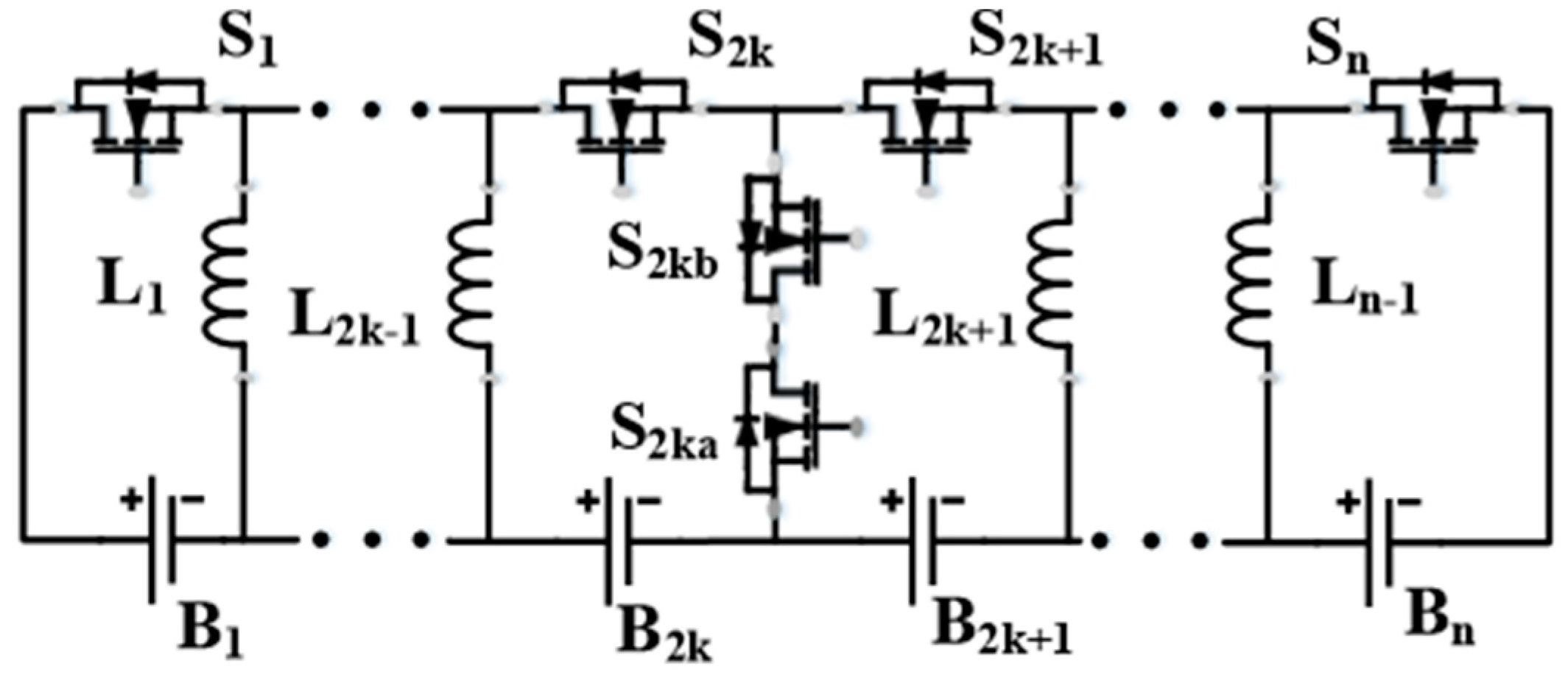
In order to equalize the cells, a large number of battery equalization circuits have been proposed [1,2,3,4,5,6,7,8,9,10,11,12,13,14,15,16]. These circuits can be divided into two types: dissipative circuits and non-dissipative circuits [4]. Among them, non-dissipative equalization circuits can be divided into three types according to the number of energy storage components: the first type is shown in Figure 1; they only have one energy storage component, so they can only have two cells working at the same time, and the equalization current is small, which leads to the slow equalization speed [5,6]. The advantages of this circuit are small volume, simple control and low cost. As shown in Figure 2, the number of the energy storage components are about half of the number of the batteries in the second type [4,7,8,9,10]. This type of circuit has several cells working at the same time and the equalization current is higher than the first type, so its equalization speed is faster than the first type. But the volume, control complexity and cost are higher than the first type. Figure 3 shows the third type, the number of energy storage components of this type is greater than or equal to the number of batteries [1,11,12,13,14,15,16,17]. This type of circuit has a large number of cells and buck-boost circuits working at the same time, and the equalization current is large, which means this type of circuit has the fastest equalization speed of the three types. Unfortunately, they also have the maximum volume, control complexity, and cost.
The volume requirements of BMS are different in different application fields. For example, the volume of BMS can be large in energy storage power stations, but the volume of BMS must be small enough in electric bicycles [18]. Since the volume of BMS is mostly determined by the volume of the equalization circuit and the volume of the equalization circuit is mostly determined by the number of energy storage components, the three types of equalization circuit mentioned above have the same disadvantage [19]. For example, a 48 V electric bicycle battery pack contains 12 batteries that need to be balanced. The first type of equalization circuit has only one inductor; one of the second type proposed in [4] has 6 inductors; and one of the third type proposed in [11] has 13 inductors. That is to say, the volume of the above three equalization circuits is fixed. However, different types of battery packs with the same voltage level have different requirements for the volume of the battery equalization circuit. If there is a need to design an equalization circuit with 2 to 5 inductors, none of the above three type can be selected [20].
In order to solve this problem, this paper proposes a novel lithium battery equalization circuit with any number of inductors (ECANI). When the voltage level of the battery pack is determined, the ECANI can select any number of inductors less than half of the number of batteries according to the design requirements. That is to say, the ECANI can design the most suitable equalization circuit volume according to the actual situation [21].
The structure and equalization principle of the ECANI is introduced in Section 2. In Section 3, simulation results show the equalization performance of the ECANI with different inductors under the same number of batteries. Section 4 compares the experimental results with the simulation results. Section 5 concludes the paper.

2. The Structure of The ECANI

The ECANI can be used in BMS, which contains any number of batteries. In this section, two, four and eight cells are used to explain the structure and equalization principle of the ECANI, respectively.

2.1. Two Cells Equalization Circuit

Only one inductor is used to transfer energy through four switches in the two cells equalization circuit as shown in Figure 4. This is the base structure of the ECANI. Two cells are in series. The specific structure of the switch (metal oxide semiconductor field effect transistor; MOSFET) in the Figure 4a is shown in the Figure 4b.
As shown in Figure 5, there are two steps to transfer energy from the high voltage cell to the lower voltage cell. Assumed that B l 1 has the high voltage and B r 1 has the lower voltage.
Step 1: Cell discharge
In a pulse-width modulation (PWM) cycle, turn on S l 1 and S l 2 , then cell B l 1 discharge and i L 1 increases.
V Bl 1 = R d i s i L 1 + L d i L 1 d t + V D 0 < t t o n
where R d i s represents the resistance of the discharge loop when S l 1 and S l 2 are turned on, L represents the inductance of L 1 , i L 1 represents the current of L 1 , V D represents the forward voltage of the body diode of the MOSFET and t o n represents the turn-on time of S l 1 and S l 2 .
According to Equation (1), i L 1 can be expressed as:
i L 1 = V Bl 1 V D R d i s V Bl 1 V D R d i s e t R d i s L = V Bl 1 V D R d i s ( 1 e t R d i s L ) 0 < t t o n
i L 1 reaches the top value   i p when   t = t o n :
i L 1 = i p = V Bl 1 V D R d i s ( 1 e t o n R d i s L )   , t = t o n
Step 2: Cell charge
When t > t o n , S l 1 and S l 2 are turned off meanwhile S r 1 and S r 2 are turned on, so L 1 charges B r 1 :
L d i L 1 d t = V Bl 1 + V D + R c h i L 1 t o n < t t d
So i L 1 can be expressed as:
i L 1 = i p e ( t t o n ) R c h L V Bl 1 + V D R c h ( 1 e ( t t o n ) R c h L ) t o n < t t d
where R c h represents the resistance of the charge loop when S r 1 and S r 2 are turned on, and t d represents the moment when i L 1 is reduced to zero [22].

2.2. Four Cells Equalization Circuit

As shown in Figure 6, when the cell number is four, the ECANI can be divided into two different structures, one with one inductor and the other with two inductors. In this paper, the two structures are simply referred to as the ECANI 4-1 and the ECANI 4-2, respectively. As shown in Figure 6a, the ECANI 4-1 is divided into two parts. The left part and the right part both contain 2 cells. Two parts of the ECANI 4-1 can be in parallel or in series and two cells in each part are in series. According to the principle in Figure 5, any cell in the left part can exchange energy with any cell in the right part through the inductor.
The ECANI 4-2 in Figure 6b is divided into two parts. The left part and the right part both contain 2 cells. Two parts of the ECANI 4-2 can be in parallel or in series and two cells in each part are in series. The ECANI 4-2 has four equalization modes [23,24].
Mode 1: One to One
As shown in Figure 7, assumed that B l 1 has the high voltage and B r 1 has the lower voltage. The principle of equalization is the same as that shown in Figure 5.
Mode 2: One to Multiple
As shown in Figure 8, it is assumed that B l 1 has the high voltage while B r 1 and B r 2 have the lower voltage. In this case, the voltages of B r 1 and B r 2 are similar so they can equalize together. There are two steps to transfer energy from the high voltage cell to the lower voltage cells. Step 1: in a PWM cycle, turn on S l 1 and S l 2 , then cell B l 1 discharge and i L 1 increases. Step 2: when t > t o n , S l 1 and S l 2 are turned off meanwhile S r 1 , S 2 and S r 3 are turned on, so L 1 charges B r 1 and B r 2 to transfer energy from B l 1 to B r 1 and B r 2 .
Mode 3: Multiple to One
As shown in Figure 9, assumed that B l 1 and B l 2 has the high voltage while B r 1 have the lower voltage. In this case, the voltages of B l 1 and B l 2 are similar so they can equalize together. There are two steps for B l 1 and B l 2 to transfer energy to   B r 1 . Step 1: in a PWM cycle, turn on S l 1 , S 2 and S l 3 , then cell B l 1 and B l 2 discharge and i L 1 increases. Step 2: when t > t o n , S l 1 , S 2 and S l 3 are turned off meanwhile S r 1 and S r 2 are turned on, so L 1 charges B r 1 to transfer energy from B l 1 and B l 2 to B r 1 .
Mode 4: Multiple to Multiple
As shown in Figure 10, it is assumed that the two parts of the ECANI 4-2 are in series and B l 1 and B l 2 has the high voltage while B r 1 and B r 2 have the lower voltage. In this case, the voltages of B l 1 and B l 2 are similar so they can equalize together. B r 1 and B r 2 can equalize together for the same reason. There are two steps for B l 1 and B l 2 to transfer energy to B r 1 and B r 2 . Step 1: in a PWM cycle, turn on S l 1 and S l 3 , then cell B l 1 and B l 2 discharge and i L 1 increases. Step 2: when t > t o n , S l 1 and S l 3 are turned off meanwhile S r 1 and S r 3 are turned on, so L 1 and L 2 charges B r 1 and B r 2 to transfer energy from B l 1 and B l 2 to B r 1 and B r 2 .
When working in modes 2–4, there will be 3 or more cells participating in the equalization in the same PWM cycle, which is beneficial in improving the equalization speed. This is one of the advantages of the ECANI [25].

2.3. Eight Cells Equalization Circuit

When there are eight cells, the ECANI can be divided into four different structures, which have one, two, three, four inductors, respectively. The four structures are simply referred to as the ECANI 8-1, the ECANI 8-2, the ECANI 8-3 and the ECANI 8-4, respectively.
As shown in Figure 11a, the ECANI 8-1 is divided into two parts. The left part and the right part both contain four cells. Two parts of the ECANI 8-1 can be in parallel or in series and four cells in each part are in series. According to the principle of the Figure 5, any cell in the left part can exchange energy with any cell in the right part through the inductor.
As shown in Figure 11b, the ECANI 8-2 is divided into four parts. Each part can be in parallel or in series and contains two cells.
One type of the ECANI 8-3 is shown in Figure 11c, which is divided into three parts. Two parts of it contain three cells and the third part contains two cells. Three parts can be in parallel or in series.
As shown in Figure 11d, the ECANI 8-4 is divided into two parts. Each part can be in parallel or in series and contains four cells.
No matter what structure is in the ECANI, as long as it contains two inductors or more, it has four equalization modes as described in Section 2.2. The ECANI 8-4 has two inductors more than the ECANI 8-2. So in mode 4, the ECANI 8-4 can have two or three or four inductors to participate in the equalization at the same time, which ensures that the ECANI 8-4 can use a more flexible equalization path and equalization strategy. That is to say, with the increase of the number of inductors, the volume of the equalization circuit will also increase, but more inductors means a more flexible equalization path and strategy, which will also increase the equalization current and eventually lead to the increase of the equalization speed. So in the specific application scenario, if you want to reduce the volume of the equalization circuit, choose the topology with less inductors, if you want to achieve faster equalization speed, choose the topology with more inductors. Therefore, the equalization circuit proposed in the manuscript can select as many inductors as possible when the volume of the equalization circuit allows, so as to ensure faster equalization speed.
Table 1 shows the comparison of inductors and switch numbers of different structures in the ECANI. It can be seen from the table that the number of inductors and switches increases with the increase of the number of cells. Under the same number of cells, the number of switches between different structures in the ECANI is almost the same.

3. Simulation

The simulation parameters are presented in Table 2. The simulation of different structures in the ECANI with four and eight cells is carried out in this paper [26].

3.1. Equalization Simulation with Four Cells

Table 3 shows the initial cell voltages of four cells. The initial voltage gap is 94 mV and the equalization threshold is 5 mV. The switch duty ratio is 40% [27].
As shown in Figure 12, the ECANI 4-1 reaches equalization at 0.2718 s and the ECANI 4-2 reaches equalization at 0.1679 s. Because the ECANI 4-2 has two inductors, it can have four equalization modes. According to Section 2.2, the ECANI 4-2 can have up to four cells participating in equalization at the same PWM cycle, and the ECANI 4-1 can only have two cells in each PWM cycle. Furthermore, when working in mode 3, the peak equalization current of the ECANI 4-2 is almost twice that of the ECANI 4-1, so the ECANI 4-2 is significantly faster than the ECANI 4-1.

3.2. Equalization Simulation with Eight Cells

Table 4 shows the initial cell voltages of eight cells. The initial voltage gap is 94 mV and the equalization threshold is 5 mV. To ensure that the circuit works in disconnect current mode (DCM), there are two kinds of switch duty ratio in the simulation [9]. When the circuit works in mode 1, 2 or 4, 20% switch duty ratio is used, and when the circuit works in mode 3, 60% switch duty ratio is used.
As shown in Figure 13 and Table 5, the order of equalization speed from fast to slow is as follows: the ECANI 8-4 > the ECANI 8-3 > the ECANI 8-2 > the ECANI 8-1. It can be seen in Table 1 that the number of switches in these four structures is almost the same, so the equalization speed of the circuit is positively related to the number of inductors in the structure. Because when the number of inductors is greater than or equal to two, there are four equalization modes, which allow several cells working at the same PWM cycle and when working in mode 3, the peak equalization current will be positively related to the number of inductors. Moreover, when the number of inductors increases, the reduction of equalization time will also decrease. Therefore, when the ECANI is used as the equalization circuit, the requirements of circuit volume and equalization speed should be considered comprehensively.

4. Experimental Results and Discussion

Equalization performance of the ECANI was verified by the experiment. The experiment platform is shown in Figure 14, which included a PC (Personal Computer), data acquisition platform, batteries, sampling circuit, drive circuit, equalization circuit, controller and oscilloscope. The experiment was carried out at room temperature. An equalization prototype with four 2.2 Ah Samsung lithium batteries was built and the parameters are summarized in Table 6, which R DS ( o n ) represents the on-resistance of MOSFET. The frequency, the equalization threshold and the initial voltages of the cells of the experiment and the simulation were the same.
Table 3 shows the initial cell voltages in Experiment 1. Figure 15 shows the four cells’ voltage waveforms during the equalization process. The initial voltage gap (94 mV) decreased to 5 mV at about 58 min 55 s. Figure 16 shows a comparison of the four cells’ voltages before and after equalization. The average final voltage of the four cells was 3.9238 V in the experiment while it was 3.9368 V in the simulation. So, the average final voltage of the experiment was 0.33% lower than that in the simulation. In the experiment, batteries had internal resistance, the inductors had resistance and magnetic leakage, the MOSFETs had on-resistance, the voltage detection of the battery had errors, and so on. As a result, the average final voltage in the experiment was lower than the simulation result.
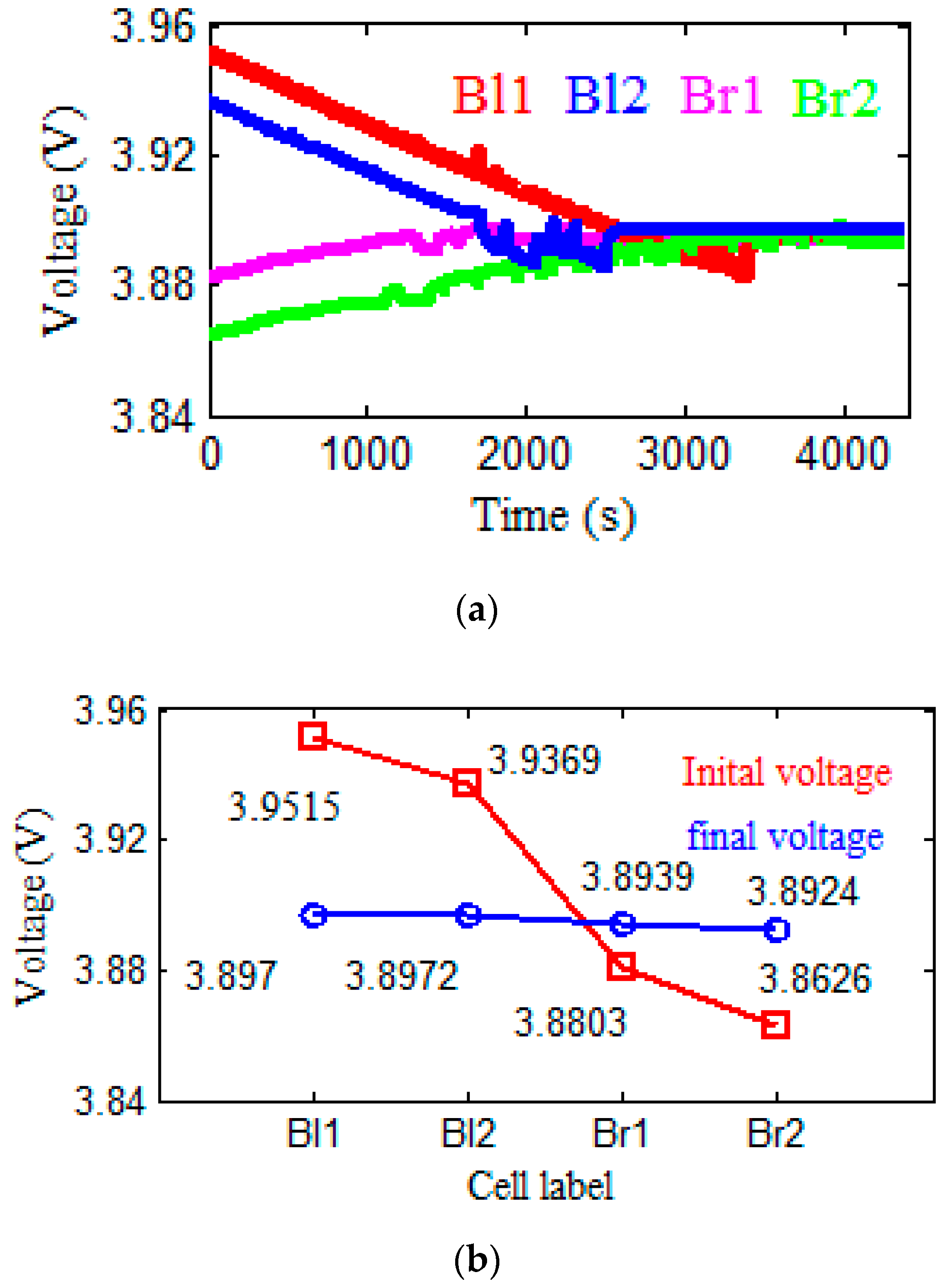
Figure 17a and Figure 18a show the voltage waveforms of Experiment 2 and Experiment 3, respectively. Figure 17b and Figure 18b show the initial and final voltages for Experiment 2 and Experiment 3, respectively. In Experiment 2, the initial voltage gap (88.9 mV) decreased to 5 mV at about 64 min 16 s. In Experiment 3, the initial voltage gap (94.5 mV) decreased to 5 mV at about 66 min 40 s. It can be seen that the ECANI can equalize the battery at different initial voltage levels.
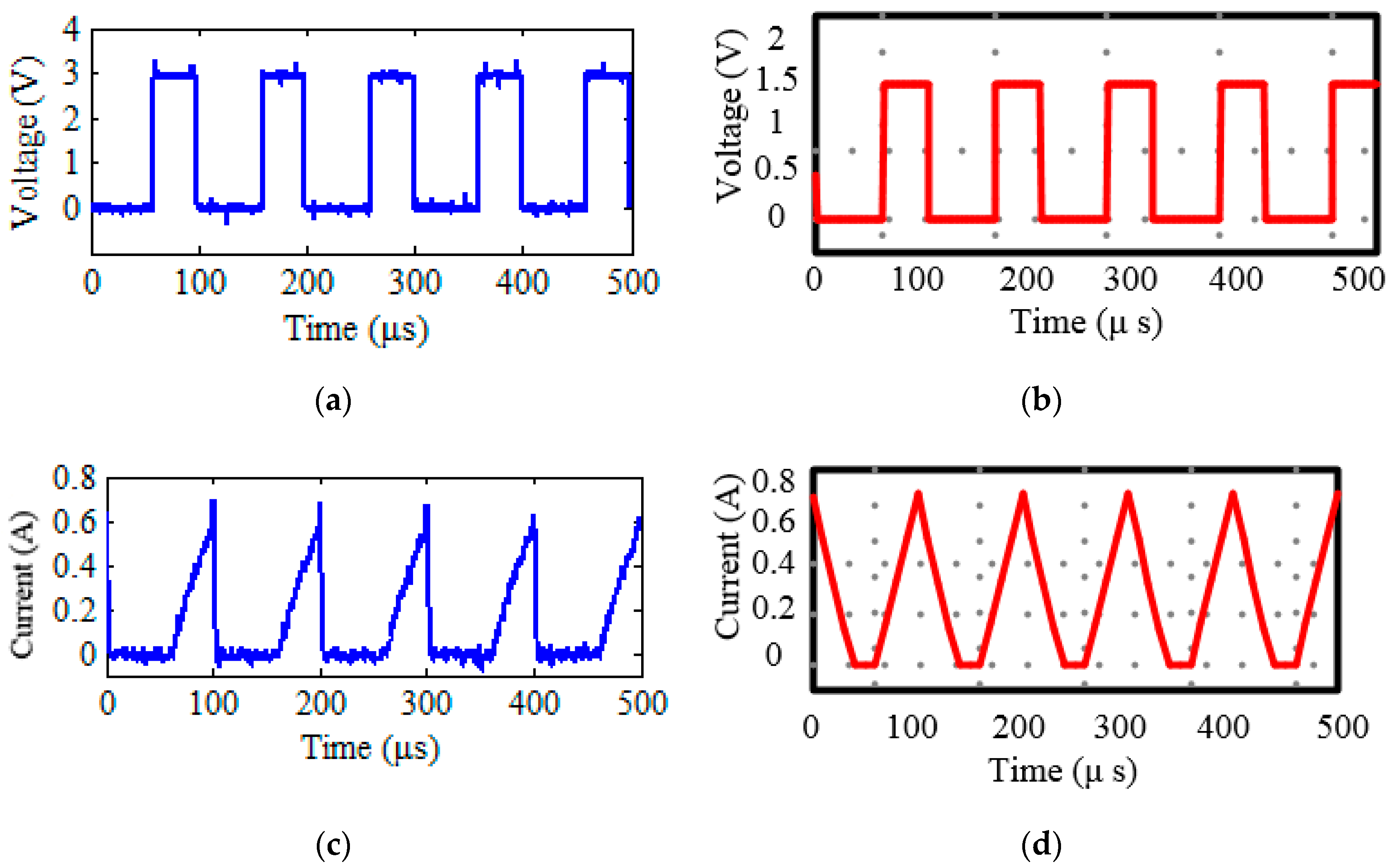
Figure 19 shows the PWM and the inductor current in mode 1 of Experiment 1 and the simulation. Figure 19c shows the current of the inductor in the experiment. The peak value of the current was 0.696 A, which is 1.69% lower than the simulation result. Considering that the resistance of the experimental circuit and the components used in the experiment were not ideal, the current error was small enough. In summary, the accuracy of the ECANI is good.

5. Conclusions

In this paper, a novel lithium battery equalization circuit with any number of inductors (ECANI) is proposed. When the voltage level of the battery pack is determined, the ECANI can select any number of inductors less than half of the number of batteries according to the design requirements, which means designing the most suitable equalization circuit volume according to the actual situation. Several different structures of the ECANI are presented in Section 2. Then the simulation result prove that the equalization speed of the ECANI is positively related to the number of inductors. Finally, by comparing the simulation and experiment of four cells, it shows that the equalization performance of the ECANI is good. In future work, we will continue to carry out the experiment of eight cells of the ECANI, and introduce the temperature factor to analyze the influence of temperature on the equalization performance of the ECANI.

Author Contributions

Conceptualization, J.L.; Data curation, C.L., X.L. and H.L.; Formal analysis, C.L.; Funding acquisition, L.K.; Methodology, C.L. and X.L.; Project administration, J.L.; Software, C.L.; Supervision, L.K.; Validation, C.L.; Writing—original draft, C.L. and X.L.; Writing—review & editing, H.L.

Funding

This research was funded by Key Area R&D Program of Guangdong Province (2019B090911001).

Acknowledgments

I would like to express my heartfelt thanks to my tutor Kang Longyun, who pointed out the research direction for me and helped me to complete the experiment. I would also like to thank anonymous commentators for taking time out of their busy schedules to review my papers.

Conflicts of Interest

The authors declare no conflict of interest.

References

  1. Ye, Y.; Cheng, K.W.E.; Fong, Y.C.; Xue, X.; Lin, J. Topology, Modeling, and Design of Switched-Capacitor-Based Cell Balancing Systems and Their Balancing Exploration. IEEE Trans. Power Electron. 2017, 32, 4444–4454. [Google Scholar] [CrossRef]
  2. Gallardo-Lozano, J.; Romero-Cadaval, E.; Milanes-Montero, M.I.; Guerrero-Martinez, M.A. Battery equalization active methods. J. Power Sources 2014, 246, 934–949. [Google Scholar] [CrossRef]
  3. Yuanmao, Y.; Cheng, K.W.E.; Yeung, Y.P.B. Zero-Current Switching Switched-Capacitor Zero-Voltage-Gap Automatic Equalization System for Series Battery String. IEEE Trans. Power Electron. 2012, 27, 3234–3242. [Google Scholar] [CrossRef]
  4. Lu, C.; Kang, L.; Wang, S.; Wang, Z.; Rao, H. A Novel Inductor-Based Non-Dissipative Equalizer. Energies 2018, 11, 2816. [Google Scholar] [CrossRef] [Green Version]
  5. Lee, S.; Lee, K.; Choi, Y.; Kang, B. Modularized Design of Active Charge Equalizer for Li-Ion Battery Pack. IEEE Trans. Ind. Electron. 2018, 65, 8697–8706. [Google Scholar] [CrossRef]
  6. Yarlagadda, S.; Hartley, T.T.; Husain, I. A Battery Management System Using an Active Charge Equalization Technique Based on a DC/DC Converter Topology. IEEE Trans. Ind. Appl. 2013, 49, 2720–2729. [Google Scholar] [CrossRef]
  7. Zhou, Z.; Shang, Y.; Duan, B.; Zhang, C. An Any-Cell(s)-to-Any-Cell(s) Equalizer Based on Bidirectional Inductor Converters for Series Connected Battery String. In Proceedings of the IEEE 11th Conference on Industrial Electronics and Applications (ICIEA), Hefei, China, 5–7 June 2016; pp. 2511–2515. [Google Scholar]
  8. Wang, S.; Kang, L.; Guo, X.; Wang, Z.; Liu, M. A Novel Layered Bidirectional Equalizer Based on a Buck-Boost Converter for Series-Connected Battery Strings. Energies 2017, 10, 1011. [Google Scholar] [CrossRef]
  9. Guo, X.; Kang, L.; Huang, Z.; Yao, Y.; Yang, H. Research on a Novel Power Inductor-Based Bidirectional Lossless Equalization Circuit for Series-Connected Battery Packs. Energies 2015, 8, 5555–5576. [Google Scholar] [CrossRef]
  10. Shang, Y.; Xia, B.; Zhang, C.; Cui, N.; Yang, J.; Mi, C.C. An Automatic Equalizer Based on Forward–Flyback Converter for Series-Connected Battery Strings. IEEE Trans. Ind. Electron. 2017, 64, 5380–5391. [Google Scholar] [CrossRef]
  11. Dong, B.; Li, Y.; Han, Y. Parallel Architecture for Battery Charge Equalization. IEEE Trans. Power Electron. 2015, 30, 4906–4913. [Google Scholar] [CrossRef]
  12. Liu, J.; Xu, M.; Zeng, J.; Wu, J.; Kai Wai Eric, C. Modified voltage equaliser based on Cockcroft–Walton voltage multipliers for series-connected supercapacitors. IET Electr. Syst. Transp. 2018, 8, 44–51. [Google Scholar] [CrossRef]
  13. Lee, Y.S.; Cheng, G.T. Quasi-Resonant Zero-Current-Switching Bidirectional Converter for Battery Equalization Applications. IEEE Trans. Power Electron. 2006, 21, 1213–1224. [Google Scholar] [CrossRef]
  14. Kirshenboim, O.; Peretz, M.M.; Zeltser, I. Non-isolated parallel balancing converter for serially connected batteries string. In Proceedings of the 2017 IEEE Applied Power Electronics Conference and Exposition (APEC), Tampa, FL, USA, 26–30 March 2017; pp. 1236–1241. [Google Scholar]
  15. Zhang, Z.; Gui, H.; Gu, D.; Yang, Y.; Ren, X. A Hierarchical Active Balancing Architecture for Lithium-Ion Batteries. IEEE Trans. Power Electron. 2017, 32, 2757–2768. [Google Scholar] [CrossRef]
  16. Baughman, A.C.; Ferdowsi, M. Double-Tiered Switched-Capacitor Battery Charge Equalization Technique. IEEE Trans. Power Electron. 2008, 55, 2277–2285. [Google Scholar] [CrossRef]
  17. Din, E.; Schaef, C.; Moffat, K.; Stauth, J.T. A Scalable Active Battery Management System with Embedded Real-Time Electrochemical Impedance Spectroscopy. IEEE Trans. Power Electron. 2017, 32, 5688–5698. [Google Scholar] [CrossRef]
  18. Lu, L.; Han, X.; Li, J.; Hua, J.; Ouyang, M. A review on the key issues for lithium-ion battery management in electric vehicles. J. Power Sources 2013, 226, 272–288. [Google Scholar] [CrossRef]
  19. Rahimi-Eichi, H.; Ojha, U.; Baronti, F.; Chow, M. Battery Management System: An Overview of Its Application in the Smart Grid and Electric Vehicles. IEEE Ind. Electron. Mag. 2013, 7, 4–16. [Google Scholar] [CrossRef]
  20. Velho, R.; Beirão, M.; Calado, M.; Pombo, J.; Fermeiro, J.; Mariano, S. Management System for Large Li-Ion Battery Packs with a New Adaptive Multistage Charging Method. Energies 2017, 10, 605. [Google Scholar] [CrossRef]
  21. Hongyu, A.W.; Yupeng, B.Y.; Chuamg, C.M. A Modeling Method of Whole Vehicle Electrical Balance Simulation System Based on Neural Network Training. IFAC-PapersOnLine 2018, 51, 87–91. [Google Scholar] [CrossRef]
  22. Li, S.; Mi, C.C.; Zhang, M. A High-Efficiency Active Battery-Balancing Circuit Using Multiwinding Transformer. IEEE Trans. Ind. Appl. 2013, 49, 198–207. [Google Scholar] [CrossRef]
  23. Bi, K.; Sun, L.; An, Q.; Duan, J. Active SOC Balancing Control Strategy for Modular Multilevel Super Capacitor Energy Storage System. IEEE Trans. Power Electron. 2019, 34, 4981–4992. [Google Scholar] [CrossRef]
  24. Bouchhima, N.; Schnierle, M.; Schulte, S.; Birke, K.P. Active model-based balancing strategy for self-reconfigurable batteries. J. Power Sources 2016, 322, 129–137. [Google Scholar] [CrossRef]
  25. Yang, Y.; Zhang, Z.; Gu, D.; Cheng, X. In Balancing strategy of lithium-ion batteries based on change rate of SOC. In Proceedings of the 2017 IEEE Applied Power Electronics Conference and Exposition (APEC), Tampa, FL, USA, 26–30 March 2017; pp. 3223–3228. [Google Scholar]
  26. Gallardo-Lozano, J.; Romero-Cadaval, E.; Milanes-Montero, M.I.; Guerrero-Martinez, M.A. A novel active battery equalization control with on-line unhealthy cell detection and cell change decision. J. Power Sources 2015, 299, 356–370. [Google Scholar] [CrossRef]
  27. Kuchak, S.V.; Voroshilov, A.N. Charge characteristics of lithium-ion accumulators under different voltages. In Proceedings of the 2016 17th International Conference of Young Specialists on Micro/Nanotechnologies and Electron Devices (EDM), Erlagol, Russia, 30 June–4 July 2016; pp. 484–485. [Google Scholar]
Figure 1. The structure of the ECANI with one inductor.
Energies 12 04764 g001
Figure 2. The inductor-based non-dissipative equalization circuit proposed in [4].
Energies 12 04764 g002
Figure 3. The layered bidirectional equalizer proposed in [8].
Energies 12 04764 g003
Figure 4. The structure of two cells equalization circuit. (a) The equalization circuit with any number of inductors (ECANI). (b) The specific structure of the switch.
Energies 12 04764 g004
Figure 5. The equalization principle of the ECANI. (a) Cell discharge. (b) Cell charge.
Energies 12 04764 g005
Figure 6. The structure of four cells equalization circuit. (a) The ECANI 4-1. (b) The ECANI 4-2.
Energies 12 04764 g006
Figure 7. The equalization principle of the ECANI 4-2 in mode 1. (a) Cell discharge. (b) Cell charge.
Energies 12 04764 g007
Figure 8. The equalization principle of the ECANI 4-2 in mode 2. (a) Cell discharge. (b) Cell charge.
Energies 12 04764 g008
Figure 9. The equalization principle of the ECANI 4-2 in mode 3. (a) Cell discharge. (b) Cell charge.
Energies 12 04764 g009
Figure 10. The equalization principle of the ECANI 4-2 in mode 4. (a) Cell discharge. (b) Cell charge.
Energies 12 04764 g010
Figure 11. The structure of eight cells equalization circuit. (a) The ECANI 8-1. (b) The ECANI 8-2. (c) The ECANI 8-3. (d) The ECANI 8-4.
Energies 12 04764 g011
Figure 12. The equalization diagram in simulation. (a) The ECANI 4-1. (b) The ECANI 4-2.
Energies 12 04764 g012
Figure 13. The equalization diagram in simulation. (a) The ECANI 8-1. (b) The ECANI 8-2. (c) The ECANI 8-3. (d) The ECANI 8-4.
Energies 12 04764 g013
Figure 14. The experiment platform of the ECANI.
Energies 12 04764 g014
Figure 15. Four cells’ voltages waveforms in the equalization process in Experiment 1.
Energies 12 04764 g015
Figure 16. The four cells’ voltages before and after equalization in Experiment 1.
Energies 12 04764 g016
Figure 17. (a) Four cells’ voltages waveforms in the equalization process in Experiment 2; (b) The four cells’ voltages before and after equalization in Experiment 2.
Energies 12 04764 g017
Figure 18. (a) Four cells’ voltages waveforms in the equalization process in Experiment 3; (b) The four cells’ voltages before and after equalization in Experiment 3.
Energies 12 04764 g018
Figure 19. The comparison of the experiment and the simulation. (a) The pulse-width modulation (PWM) in the experiment. (b) The PWM in the simulation. (c) The inductor current in the experiment in mode 1. (d) The inductor current in the simulation in mode 1.
Energies 12 04764 g019
Table 1. Comparison of different structures in the ECANI.
StructureCellsInductorsSwitches
The ECANI 2-1214
The ECANI 4-1418
The ECANI 4-2428
The ECANI 8-18116
The ECANI 8-28214
The ECANI 8-38314
The ECANI 8-48414
The ECANI n-mnm(m + n + 1)–2n
Table 2. The parameters of the simulation.
PlatformBatterySwitching FrequencyDuty CycleInductanceParasitic Capacitances and Parasitic Inductances
PSIM (Power Simulation) 9.0Substituted by 1 F capacitor10 kHz20%, 40%, 60%100 μHignored
Table 3. The initial cell voltages of four cells (voltage unit: V).
Cell LabelBl1Bl2Br3Br4
Voltage3.993.9613.913.896
Table 4. The initial cell voltages of eight cells (voltage unit: V).
Cell LabelBl1Bl2Bl3Bl4Br1Br2Br3Br4
Voltage3.993.9753.9613.9453.933.923.913.896
Table 5. The equalization time of four structures (time unit: s).
The ECANI 8-1The ECANI 8-2The ECANI 8-3The ECANI 8-4
Time1.21630.43560.27530.2594
Table 6. Component values used for the ECANI.
ParametersComponentLabelValueValue
Battery stringSamsung lithium battery B l 1 ,   B l 2 ,   B r 1 ,   B r 2 2.2 Ah-
CircuitMOSFET S 1 S 4 ,   S l 1 S l 4 ,   S r 1 S r 4 IRF3205PBF R DS ( o n ) < 0.008   Ω
-Inductor L 1 ,   L 2 100.1 μ H , 100.5 μ H R < 0.069   Ω
R < 0.0632   Ω