1. Introduction
Permanent magnet motors (PMMs) have advantages of high torque density, high efficiency, and high power factor, suitable for low-speed and high-torque direct-drive applications such as electric vehicles, industrial robots, and aerospace fields [
1,
2,
3,
4]. Therefore, research on low-speed and high-torque direct drive permanent magnet motors is by many scholars.
Research on low-speed and large-torque direct-drive permanent magnet motors focuses on the following four types of motors: traditional permanent magnet synchronous motor, permanent magnet transverse flux motor, magnetic-field modulated motor, and permanent disk motor [
5]. The advantages of the motor with fractional slot concentrated windings primarily include shorter end turns, high torque density, and high slot fill factor [
6,
7], which renders it a promising candidate for low-speed and high-torque direct-drive applications. The use of anti-salient pole structure reduces the leakage flux and harmonic content of the motor to improve the operation characteristics of the motor [
8]. In [
9], the influence of the shape and distribution of permanent magnets on the motor performance was explored. The traditional permanent magnet synchronous motor has a simple structure and high reliability but has a long axial length and large volume. The permanent magnetic transverse flux motor is suitable for low-speed and high-torque direct drive owing to its small polar distance and large torque [
10]; however, the motor structure is complex, and its power factor is small [
11,
12]. Literature [
13] proposed a low-speed magnetic-field modulating motor based on the principle of magnetic field modulation. Nevertheless, the motors have difficulties in the fixing and processing of magnetic field modulation rings, and the power factor of the motor is low [
14]. In literature [
15,
16], the permanent disc motor (PDM) has merits of light weight, small size, and compact structure. Professor Cheng presents a disc permanent magnet linear synchronous machine with back iron in [
17], which has a very low line current distortion and a very wide range of operating speed. But the PDM has a strict requirement on configuration accuracy, suitable for thin installations.
In order to improve the torque density of low-speed and large-torque direct-drive motors, the dual-stator/double-rotor structure is increasingly combined with a permanent disk motor and transverse flux motor for topology innovation, which can effectively improve the utilization rate of the punch and make full use of internal space to improve efficiency and torque density [
2,
18]. The PMMs in [
19,
20] adopt toroidal windings, which shortens the winding terminal, increases the heat dissipation area, and avoids the crossing of the winding terminal. Furthermore, the installation and fixing of the toroidal windings are very simple. To further improve the output torque and widen the operating speed range of the PMM with toroidal windings under certain conditions of mechanical size, a novel direct-drive permanent magnet synchronous motor with toroidal windings (N-TWDDPMSM) is presented herein. Under the same power grade and mechanical size, the output torque value of N-TWDDPMSM is twice that of the traditional permanent magnet synchronous motor (T-PMSM) and the traditional permanent magnet synchronous motor with toroidal windings (T-TWPMSM), and the speed of the N-TWDDPMSM is half that of the T-PMSM and T-TWPMSM. Therefore, the N-TWDDPMSM is a promising candidate for electric vehicles applications.
The remainder of the paper is organized as follows:
Section 2 not only introduces the structure and the winding connected method of N-TWDDPMSM but also analyses the operating principle of N-TWDDPMSM. In
Section 3, the finite-element models (FEMs) of different motors are established using Magnet software under the same criteria.
Section 4 presents the comparisons between three kinds of motors from the aspect of armature magnetic field distribution and operating characteristics. A brief summary of this paper as well as the directions for future research work are proposed in
Section 5.
2. Structure and Mechanism Analysis of N-TWDDPMSM
2.1. Structure of N-TWDDPMSM
The diagrammatic sketches of the N-TWDDPMSM are shown in
Figure 1.
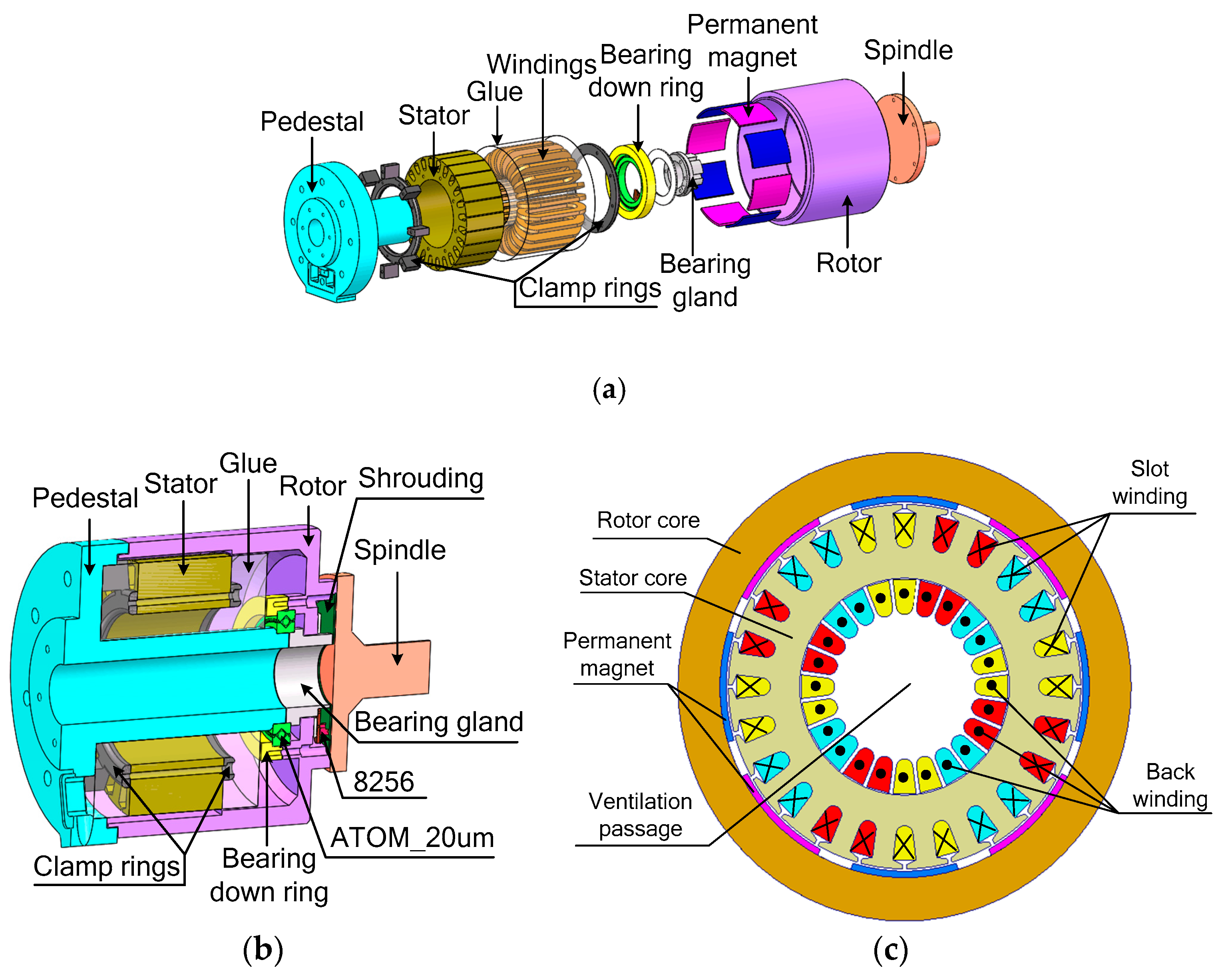
Figure 1a–c respectively describe the exploded view of the mechanical structure of the N-TWDDPMSM prototype, the section view of the mechanical structure of the N-TWDDPMSM prototype, and the assumption diagram of the simulation structure of the N-TWDDPMSM. It can be seen in
Figure 1a,b that the stator is mounted on the pedestal using clamp rings. Moreover, the stator is sealed using glue to make a protection for the windings. Then, the components bearing down ring, ATOM_20 μm, containing steel balls, and bearing gland are used to determine the relationship between the rotor and the stator. The bearing gland is installed on the pedestal and the spindle is assembled into the rotor.
Figure 1c shows the assumption diagram of the simulation structure of the N-TWDDPMSM. It is noted that all windings of the motor are wrapped around the stator yoke in a toroidal shape, and the incoming end of windings is not only located on the same side of the stator, but also has the same orientation. In addition, the free space inside the stator can be used as a ventilation passage, which increases the heat dissipation area on the stator and improves the thermal performance.
2.2. Winding Configuration of N-TWDDPMSM
As shown in
Table 1,
Table 2 and
Table 3, the winding configurations for the traditional permanent magnet synchronous motor (T-PMSM), traditional permanent magnet synchronous motor with toroidal windings (T-TWPMSM), and N-TWDDPMSM are depicted, in which the signs ‘⨯’ and ‘⦁’ respectively denote the winding flowing into and out of the page.
In addition to the information in
Table 1,
Table 2 and
Table 3, the stator structure of the three motors is shown in
Figure 2. It can be seen from
Figure 2 that the stator windings of the N-TWDDPMSM are different from the ones of the other two motors. It should be noted that not only are the stator windings of the proposed motor transferred from the stator tooth to the stator yoke, but also the incoming line ends of the stator windings are on the same side and have the same incoming direction.
2.3. Mechanism Analysis
In order to clearly describe the operating principle of the N-TWDDPMSM, it is analyzed by using the three-slot unit motor as an example in this subsection. The current waveform supplied to the three-phase windings is shown in
Figure 3. The current flowing into the winding is defined as ‘+’ and the current flowing from the winding as ‘−’. Therefore, in addition to the current of each phase winding at different times, the current directions of the three-phase winding coils at different times are shown in
Table 4. Based on the distributions of the three-phase winding currents at different times and the faraday law of electromagnetic induction, the armature magnetic field distribution in each moment is described in detail.
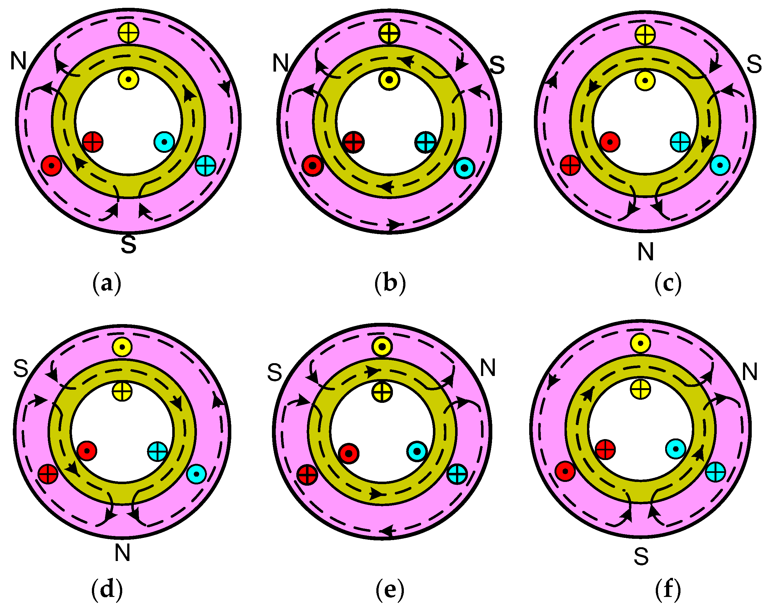
Figure 4a–f shows the armature magnetic fields corresponding to the current distributions from Time 1 to Time 6, respectively.
Comparing the graphs in
Figure 4, the comparison of the magnetic fields at Time 1 and Time 2 shows that the N pole of the armature magnetic field has no movement, but the S pole moves 120° in the counter-clockwise direction. Compared with the situations at Time 2 and Time 3, the N pole has moved by 120° in the counter-clockwise direction, while the S pole has no movement. The comparison of the magnetic fields at Time 3 and Time 4 shows that the N pole does not move, and the S pole moves 120° in the counter-clockwise direction. Comparing the distribution of the corresponding armature magnetic fields at Time 4 and Time 5, the S pole shows no movement, and the N pole moves 120° in the counter-clockwise direction. The magnetic field at Time 5 is compared with the magnetic field at Time 6, and the result shows that at the S pole, the armature magnetic field has moved by 120° in the counter-clockwise direction, while the N pole does not move. As a result, it can be concluded that the armature magnetic field of the three-slot unit motor forms a pair of poles and changes periodically.
3. Design of the Proposed Motor
To verify the feasibility of the proposed motor, the N-TWDDPMSM model is designed and compared with the traditional motor. During the design process, some rules and constraints are followed for a fair comparison.
(1) The outer rotor dimensions and the axial lengths of the N-TWDDPMSM and T-TWPMSM are the same as those of the T-PMSM; therefore, the three motors have the same volumes. The rotor outer diameter is 216 mm and the axial length is 68 mm.
(2) The N-TWDDPMSM, T-TWPMSM, and T-PMSM have the same pole arc coefficient and magnetizing height of a permanent magnet; therefore, the total amount of permanent magnets in the three kinds of motors are the same.
(3) The N-TWDDPMSM, T-TWPMSM, and T-TWPMS have the same air gap.
(4) The outer diameter, inner diameter, and channel-shaped size of the stator are also the same for both the T-TWPMSM and T-PMSM.
(5) The wire diameter must be consistent with the conventional motor.
Based on the principles above, the primary parameters of the T-PMSM, T-TWPMSM, and N-TWDDPMSM are summarized in
Table 5.
4. Finite-Element Modeling and Characteristics Analysis
4.1. Establishment of Finite-Element Model
With the parameters reported in
Table 5, the FEMs of different structures of motors are respectively established to compare characteristics the armature magnetic field distributions and analyze the operating characteristics under no-load and on load conditions. According to the simulation results, the no-load air-gap flux density, no-load back-EMF, power-angle characteristics, and loss characteristics are analyzed. The FEM of the N-TWDDPMSM is shown in
Figure 5.
4.2. Armature Magnetic Field Distribution of N-TWDDPMSM
Figure 6a–c describes the armature magnetic field distributions of the three motors, and the flux density distributions of armature magnetic field for three motors are compared in
Figure 7. It can be found that the armature magnetic fields are generated and are uniformly distributed in the circumferential direction when the motors are excited by three-phase AC currents. Moreover, compared with the T-PMSM and T-TWPMSM, the poles of the armature magnetic field of the proposed motor have increased by two times, which means that the output torque value of N-TWDDPMSM is twice that of the other motors and the speed of the N-TWDDPMSM is half that of the T-PMSM and T-TWPMSM. Therefore, the N-TWDDPMSM is a promising candidate for low-speed and high-torque direct drive applications.
4.3. No-Load Characteristic
The permanent magnet inside the PMSM is not only a magnetic source but also an important part of the magnetic circuit in the motor; therefore, the magnetic field distributions of the motor are more complicated [
21]. To analyze the internal magnetic field intuitively and effectively, the magnetic flux distribution, air-gap flux density, and back-EMF under no-load condition of the three motors are compared and analyzed.
4.3.1. Analysis of Magnetic Field Distribution under No Load
Figure 8a–c presents respectively the magnetic flux distribution diagrams of the T-PMSM, T-TWPMSM, and N-TWDDPMSM under no load.
Figure 8 shows that the magnetic flux lines of the motors are closed by the stator yoke, the teeth, and the air gap along the magnetization direction of the motor to form a loop. The magnetic flux lines of the T-TWPMSM and T-PMSM both appear as two pairs of poles, while the N-TWDDPMSM has four pairs of poles. Therefore, the rated speed of the N-TWDDPMSM is degraded by 50%, and the rated output torque of the N-TWDDPMSM is higher than that of the other motors.
4.3.2. Comparison and Analysis of Air-gap Flux Density and Back-EMF under No Load
The air-gap flux density waveforms and the corresponding harmonics of the N-TWDDPMSM, T-TWPMSM, and T-PMSM are shown in
Figure 9.
Figure 10 shows the no-load back-EMF waveforms and the spectral analysis of the three motors.
Figure 9a depicts the air-gap flux density waveforms of the three motors.
Figure 9b shows the spectral analysis of the air-gap flux density of each motor. As shown in
Figure 9b, the amplitudes of the fundamental component of the air-gap flux density in the N-TWDDPMSM, T-TWPMSM, and T-PMSM are 0.981T, 0.798T, and 0.798T, respectively. Additionally, the total harmonic distortions (THDs) of different motors are 21.65%, 22.69%, and 22.55%, respectively. According to the result of the spectral analysis, not only are the harmonic components of the air-gap flux density of the T-TWPMSM the same as the T-PMSM, but the value of each harmonic is also approximately equal. The primary reason is that the structures besides the winding connected modes of the two motors are identical. In comparisons with the T-TWPMSM and T-PMSM, the fundamental amplitude in the N-TWDDPMSM is the largest and the value of the third harmonic decreases.
The no-load back-EMF of the three motors is shown in
Figure 10. It can be seen from
Figure 10a that the three motors have a symmetric back-EMF waveform. Therefore, there are no even harmonics in the back-EMF waveforms of the three motors [
22]. Applying Fourier analysis,
Figure 10b shows that the back-EMF waveforms of the three motors do not have even harmonics, and the peak value of the fundamental component of the back-EMF of the N-TWDDPMSM, T-TWPMSM, and T-PMSM are 298.96 V, 306.71 V, and 311.89 V, respectively. Because the voltage of the phase resistances is ignored, the DC-link bus voltages of the three motors are approximately equal. In addition, the THDs of the three motors are 4.16%, 6.57%, and 6.00%, respectively. Therefore, from the viewpoint of the back-EMF characteristics, not only does the N-TWDDPMSM exhibit the lowest back-EMF magnitude, the harmonics of the proposed motor are also the least, and the sinusoidal waveform of the no-load back-EMF is better. In addition, we found that the motor can effectively suppress the generation of the third and fifth harmonics of the no-load back-EMF.
4.4. Load Characteristic
Using the finite-element method, the models excited by a voltage source in the N-TWDDPMSM, T-TWPMSM, and T-PMSM are respectively established to study the power-angle characteristics and the losses characteristics.
4.4.1. Power-angle Characteristic
The comparisons of the torques and root-mean-square (RMS) currents of the three different motors are shown in
Figure 11.
Figure 11a describes the torque-angle waveforms of the three motors and
Figure 11b shows the RMS current-angle waveforms of the motors.
Figure 11 shows that the torque and RMS current of the N-TWDDPMSM at different electrical degrees are the largest.
Figure 11a shows that the average torques of the N-TWDDPMSM, T-TWPMSM, and T-PMSM respectively reach maximum values of 110.22 N·m, 62.78 N·m, and 65.50 N·m when the electrical degree is 90. Compared with the T-TWPMSM and T-PMSM, the maximum torque of the N-TWDDPMSM has increased by 75.56% and 68.27%, respectively. When the three motors are simultaneously operating at 30 electrical degrees, the output torques of the N-TWDDPMSM, T-TWPMSM, and T-PMSM reach 47.60 N·m, 20.77 N·m, and 19.45 N·m, which shows that, compared with the T-PMSM and T-TWPMSM, the output torque of the N-TWDDPMSM is respectively increased by 1.29 times and 1.45 times, although the pole pairs of the N-TWDDPMSM are doubled and the rated speed of the N-TWDDPMSM is reduced by half. Consequently, the output torque of the N-TWDDPMSM dramatically improved under of the same power grade and mechanical size, and significant improvement in torque to volume ratio is noted. In addition, the utilization of permanent magnets is also improved because the total volume of the permanent magnets and the motor constant for the three motors is equal.
Figure 11b reveals that the RMS current of each motor is approximately proportional to the electrical angle, and the RMS current values versus different angles of the T-TWPMSM are close to those of the T-PMSM. Moreover, the comparison of
Figure 11a,b indicates that the N-TWDDPMSM has the merit of small current when the three motors are operated under the same load, and the output torque of N-TWDDPMSM is dramatically improved when the three motors are excited by the same current. Therefore, based on the same power grade and mechanical size, significant improvements in torque per ampere and torque to volume ratio are noted for the N-TWDDPMSM compared with the T-PMSM and T-TWPMSM.
Figure 12 compares the waveforms of efficiency, power factor, and force energy index of the three motors, whereby the force energy index means the product of efficiency and power factor. It can be seen from
Figure 12 that the T-TWPMSM and T-PMSM are basically the same in terms of efficiency, power factor, and force index. The operating characteristics of the T-TWPMSM are similar to the T-PMSM. Therefore, the operating characteristics of the motor do not change when only the winding mode is changed. However, compared with the T-TWPMSM and T-PMSM, the efficiency and power factor of the N-TWDDPMSM are reduced, which causes the force index of the N-TWDDPMSM to be the least. Further, the overall performances of the proposed motor degraded.
4.4.2. Rated Operating Characteristic
A. Speed Characteristic
As shown in
Figure 13, the speeds of the three motors are described. It can be seen in
Figure 13 that the speed of the N-TWDDPMSM is reduced by half, compared with the speeds of the T-PMSM and T-TWPMSM. The reason for this phenomenon is that the number of pole pairs of the armature field for the N-TWDDPMSM is doubled in comparison with the T-PMSM and T-TWPMSM.
B. Torque Characteristic
Figure 14 describes the output torque of the three motors when they are under rated operation.
Figure 14a shows the torque dependence on rotor position of the three motors, and
Figure 14b analyzes the Fourier components of each motors’ torque. It can be found that the zero-sequence component in the Fourier components is the average output torque of each motor. The average output torques of the N-TWDDPMSM, T-TWPMSM, and T-PMSM are 38.20 N·m, 19.10 N·m, and 19.10 N·m, respectively, which shows that the rated torque is twice that of the T-PMSM and T-TWPMSM.
C. Losses Characteristic
The motor losses usually include rotor losses and stator losses, which have a large effect on the efficiency and power factor of the motor. However, the electrical conductivity of the permanent magnets on the rotor is only
s/m, which makes the eddy current losses in the motors very small. The losses in the rotor steel of the T-PMSM, T-TWPMSM, and N-TWDDPMSM are 0.44 W, 0.42 W, and 0.42 W, respectively, which were obtained using Magnet software. The losses in the rotor are small and almost negligible compared with the losses in the stator. Therefore, we herein only compare and analyze the copper losses and iron losses in the stator of the different motors, as shown in
Figure 15.
Figure 15 shows the stator losses of the N-TWDDPMSM, T-TWPMSM, and T-PMSM under rated operation. We found that the total losses of the three motors in the rated operation are 221.66 W, 172.22 W, and 166.48 W, respectively. Among them, the copper losses are 175.66 W, 117.28 W, and 111.96 W, respectively. Therefore, from the viewpoint of losses in the motor, the iron loss in the N-TWDDPMSM is reduced by 16.28% and 15.63%, respectively, compared with the T-TWPMSM and T-PMSM, whereas the total consumption of the N-TWDDPMSM is the largest among the three types of motors. Consequently, the excessive copper consumption of the N-TWDDPMSM causes the efficiency and power factor of the proposed motor to be smaller than those of the other motors, and the comprehensive quality of the N-TWDDPMSM is reduced.
5. Conclusions
Herein, a novel N-TWDDPMSM is proposed. In addition to the introduction of the topology and operating principle of the N-TWDDPMSM, the key operating characteristics of the N-TWDDPMSM, T-TWPMSM, and T-PMSM are compared based on the same power grade, overall dimensions, current density, and DC-link bus voltage. Not only is the feasibility and superiority of the N-TWDDPMSM verified, but it is also concluded that the N-TWDDPMSM possesses some merits, as listed below.
(1) Unlike the T-PMSM and T-TWPMSM, all coils of the N-TWDDPMSM are removed from stator tooth to the stator yoke and have the same orientation, which results in a significant increment of the poles for the armature magnetic field. Hence, the rated speed is reduced by half.
(2) Based on the same power grade and mechanical size, significant improvements in torque per ampere and torque to weight ratio are noted for the N-TWDDPMSM compared with the T-PMSM and T-TWPMSM. Furthermore, the N-TWDDPMSM has the merits of low speed and high utilization of the permanent magnets.
(3) Compared with the T-PMSM and T-TWPMSM, the THD in the N-TWDDPMSM is reduced and the operation is smoother.
(4) From the viewpoint of losses, the N-TWDDPMSM can effectively restrain the generation of iron loss on the stator.
(5) The free space for the windings inside the stator can be used as a ventilation passage, thus increasing the heat dissipation area of the stator. Consequently, the heat dissipation performance of the motor is improved. Nevertheless, the inner rotor can be placed inside the stator, which can not only improve the utilization of windings but can also result in better operating characteristics of the motor.
The primary drawback of the N-TWDDPMSM is the large copper losses, which leads to a lower efficiency and power factor than in the traditional ones. Therefore, the optimization of motor performance will be a future investigation and shall be reported soon. On the other hand, the dual-rotor permanent magnet synchronous motor is considered to improve performance of the N-TWDDPMSM.


