Article

Research on Hybrid Microgrid Based on Simultaneous AC and DC Distribution Network and Its Power Router

1
School of Electrical Engineering, Shandong University, Ji’nan 250100, China
2
Library of Shandong University, Ji’nan 250100, China
*
Author to whom correspondence should be addressed.
Energies 2019, 12(6), 1077; https://doi.org/10.3390/en12061077
Submission received: 23 January 2019 / Revised: 14 March 2019 / Accepted: 16 March 2019 / Published: 20 March 2019
(This article belongs to the Section A1: Smart Grids and Microgrids)

Abstract

:
Under the dual pressure of environmental pollution and energy crisis, the global energy consumption structure reform deepens unceasingly and the concept of energy internet has developed rapidly. The widespread volatility, randomness, and uncertainty of distributed new energy generation impose new requirements on distribution systems. The zigzag transformer is used as the coupling and isolating device for simultaneous AC–DC transmission. The basic principle and structure of simultaneous AC–DC power distribution network is analyzed. The topology structure of the simultaneous AC–DC hybrid microgrid and basic operating principle of the microgrid under different operating modes are proposed for the distributed power grid technology. Combined with power electronic technology, a modular multi-interface structure of power routers applied to AC–DC hybrid microgrid and its control strategy are proposed to realize the power routing control of microgrid and ensure reliable operation control of the microgrid. By building the model of simultaneous AC–DC hybrid microgrid and its power router, the rationality and effectiveness of the power router for microgrid routing control are verified.

1. Introduction

With the depletion of fossil fuels and the increasingly prominent changes of climate and environment, countries around the world are striving for a more efficient, environmentally friendly, and sustainable energy utilization model in order to improve the energy consumption structure dominated by fossil energy [1,2,3]. The development of information internet and new energy technologies has provided necessary technical support for the development of smart grids under the new situation. A new structure of energy supply and demand with energy internet as the main form is being formed [4,5,6,7].
The new energy distributed generation has small capacity, strong power fluctuations, and randomness. A large number of power conversion devices are required to be dispersedly connected to the traditional AC distribution network, which reduces the utilization efficiency of the distributed source and affects the stability of the power grid, while increases the complexity of power relay protection configuration [8,9,10]. The microgrid is an autonomous system of power generation and distribution that integrates distributed generation, energy storage devices, various power conversion devices, traditional loads, and new types of loads [11,12,13]. With the help of power electronics and modern control theory, the microgrid is an efficient and reliable distributed generation scheme. It can realize efficient interconnection with distribution networks [14,15].
Since the 1950s, scholars from the former Soviet Union, Japan, and other countries have studied the transmission capacity of simultaneous AC–DC transmission, feasibility of the circuit structure, the system economy, and so on. Simultaneous AC–DC transmission technology superimposes DC power on existing AC power lines to fully tap transmission capacity of the line [16,17]. Simultaneous AC–DC power transmission has good development prospects in improving the transmission capacity of the line and the transient stability of the transmission system [18,19]. With the development of power electronics and modern control theory, simultaneous AC–DC transmission technology has received renewed attention as a flexible AC transmission technology (FACTS) [20].
We combined the small quantity and more facets of distributed generation with a large-scale distribution network, under the background of rapid development of distributed generation [21]. Some scholars put forward the basic conception and principle scheme of distribution network based on simultaneous AC–DC transmission, which can be used for the distributed generation grid connected [22,23,24]. The simultaneous transmission of AC power and DC power can be achieved [25,26].
In this paper, the transformation and upgrading of a traditional AC distribution network by using Z-transformers achieved simultaneous AC–DC power distribution. And its rationality scheme is analyzed and studied. The concept of micropower network is introduced into a simultaneous AC–DC power distribution scheme. The power router structure and its control strategy are proposed, which are based on power electronics technology. The model of simultaneous AC–DC hybrid microgrid and its power router were built in the MATLAB/Simulink simulation platform. The simulation results under different operating modes of the microgrid verify the rationality of the AC–DC hybrid microgrid and the effectiveness of the power router control.

2. Simultaneous AC–DC Power Distribution Network

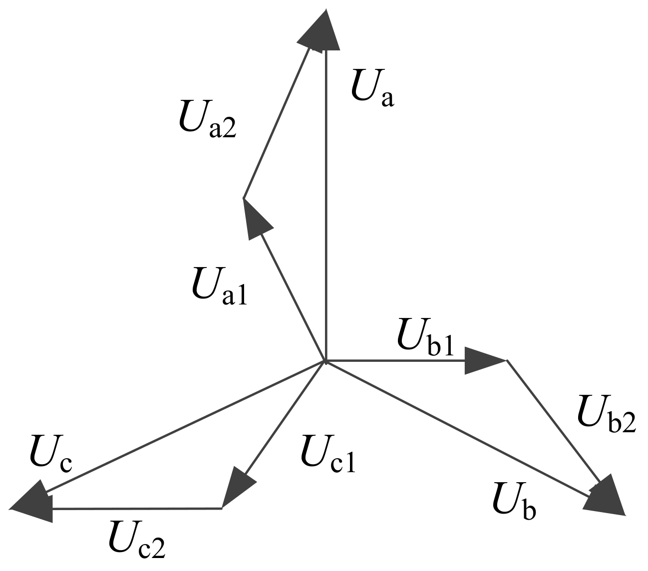
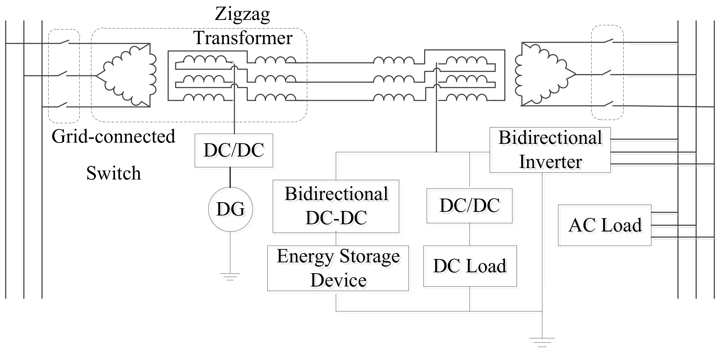
The Principle of Simultaneous AC–DC Power Distribution Network

The single-loop structure of the simultaneous AC–DC distribution network is shown in Figure 1 [22]. DC power and AC power are transmitted through the same three-phase line, and the DC current drawn from the DC current decoupling device forms a DC current loop through grounded or a dedicated ground line.
As shown in Figure 2, replacing the traditional power transformer with zigzag transformer, the DC current is superimposed on a three-phase AC line through the secondary winding neutral of the zigzag transformer. The relationship between the three-phase AC voltage vectors of the secondary side of the zigzag transformer is shown in Figure 3. By configuring the same number of winding turns of two zigzag connections in each phase, the DC bias phenomenon caused by DC current injection can be minimized.
AC and DC need to be coupled and decoupled by zigzag transformer. When the Z-type transformer is injected with DC current, the generated magnetic fluxes cancel each other. The magnetic flux on the three-phase iron core column does not change, and the working point of the iron core on the magnetization curve does not change. Therefore, there is basically no core saturation. The zigzag transformer acts as both a DC injection device and an AC/DC isolation device. AC and DC power are decoupled at the end of the line through a symmetrical structure.
AC–DC superimposed voltage and power configuration need to meet certain constraints according to the operating conditions of the distribution network. DC and AC distribution networks have little difference in the requirements for the design and construction of mechanical structures for overhead lines and cable lines [27]. Therefore, electrical requirements and environmental requirements are mainly considered when formulating DC injection rules.
There is a sinusoidal alternating electric field superimposed on the DC component of the power line after the three-phase line is injected into the DC. The peak voltage of the single-phase line to ground is Um. Since the creepage distance of the DC power line is twice that of AC power line [28]. In order to ensure the insulation level of the original distribution network is unchanged, the original line voltage is UAC. The superposed DC voltage component and AC component should meet the condition of following constraint,
U m = 2 U a c 3 + U d c 2 U A C 3
2 U ac 3 + U dc < 0
The temperature rise current that the conductor of the power line allows is Itb. The superposition of DC current component and AC current component need to meet the following constraint,
I a c 2 + I d c 3 2 < I t b 2
In order to ensure the normal use of AC circuit breakers, the line current has at least one zero-crossing point per period. The valley value of AC–DC superimposed current In should follow these constraints:
I n = 2 I a c + 1 3 I d c = 2 P a c 3 U a c cos φ + P d c 3 U d c < 0
If I dc = x I tb , U dc = k U AC , then we can infer, 0 < x 6 , 0 < k < 1 / 6 . Under this rule, the line voltage meets the principle that without raising the insulation level of the line and satisfies various operating conditions at the same time. Figure 4 shows the single-phase ground voltage waveform of the pure AC distribution network and AC&DC distribution network. In the AC&DC distribution network, the AC voltage waveform is lifted horizontally due to the superposition of the DC voltage so the positive peak of the voltage waveform of the two systems is equal but the voltage waveform isn’t coincident.

3. Simultaneous AC–DC Hybrid Microgrid

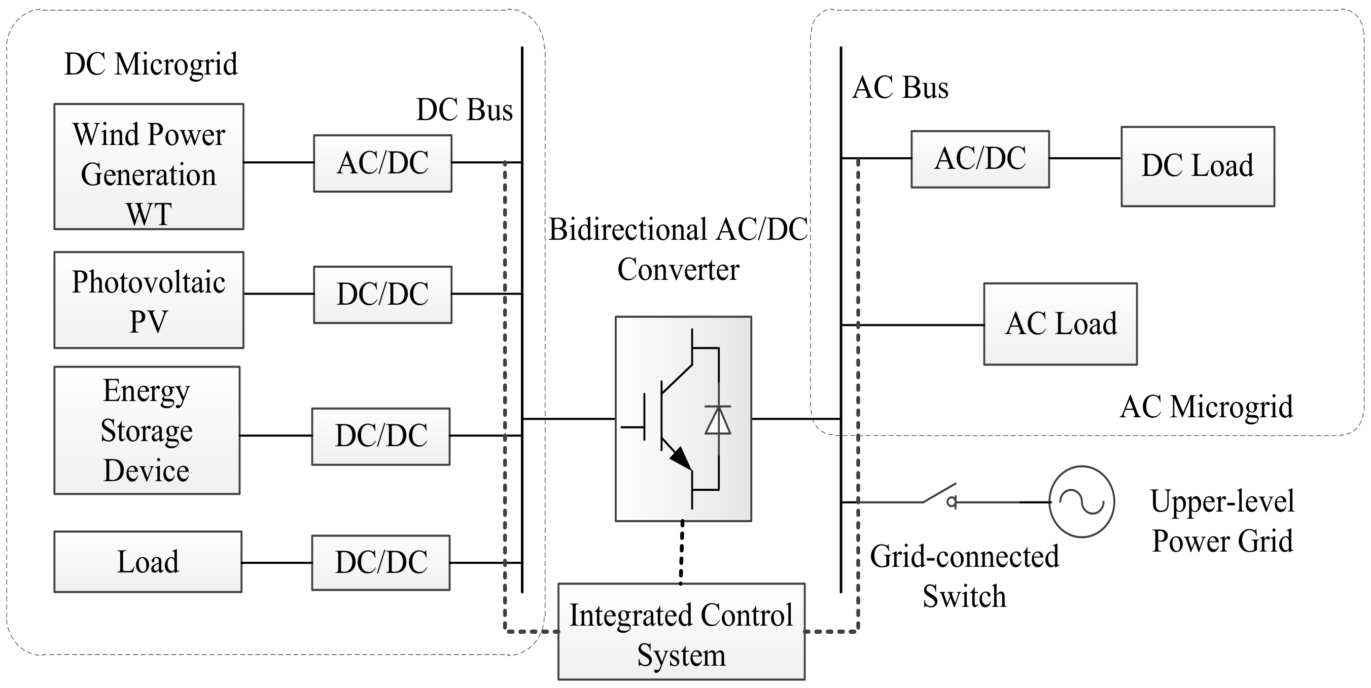
3.1. Simultaneous AC–DC Microgrid Structure

As shown in Figure 5, the zigzag transformer neutral line leads out the DC bus. DC load can be directly connected to DC bus via DC/DC converter. Distributed generation (DG) and energy storage devices both cooperate with DC/DC converters and can be used as DC power, which can achieve distributed generation incorporated into simultaneous AC–DC hybrid microgrids. Compared with the distributed DC/DC and DC/AC two-stage conversion of distributed generation into AC distribution network, the economic efficiency is better, and the control difficulty is lower. There are no constraints such as frequency and phase synchronization required for incorporation into the AC bus.
The secondary side of the zigzag transformer at the end of the distribution network leads the AC bus of the microgrid, for the microgrid AC load supply. The AC bus and the DC bus are connected through a bidirectional AC–DC converter to achieve bidirectional transmission of power between the AC and DC buses. The zigzag transformer provides a low-impedance path for the DC current and maintains a high-impedance state for the three-phase AC current. At the same time, the injection of DC current into the three-phase line does not affect the three-phase voltage of the secondary winding, but the insulation of the transformer needs to be improved due to the increase of the winding phase voltage.
In the event of a fault in the distribution line, due to the presence of the DC component, the short-circuit current will increase the DC forced component, and the line current and the amplitude of the voltage change are more obvious than the AC system.

3.2. Microgrid Operating Characteristics

Figure 6 shows the simplified structure of the microgrid. It can be divided into DC microgrid and AC microgrid.
As a universal access platform for distributed generation and energy storage devices and loads, the DC bus can implement integrated control of DC microgrids easily, while improving system scalability. The AC microgrid is directly connected to the distribution network (main grid). The AC bus is connected to the distribution network through a grid-connected switch. Bidirectional controllable power flow between two microgrids is achieved through bidirectional AC–DC converters so that two systems can support each other.
Simultaneous AC–DC microgrids can operate in both grid-connected and islanding modes. As an active load of the distribution network, the microgrid cannot impact stable operation of the distribution network. It is necessary to form coordination among distributed generation within the microgrid to ensure operation stability and certain adjustable margins.

3.3. Hybrid Energy Storage System

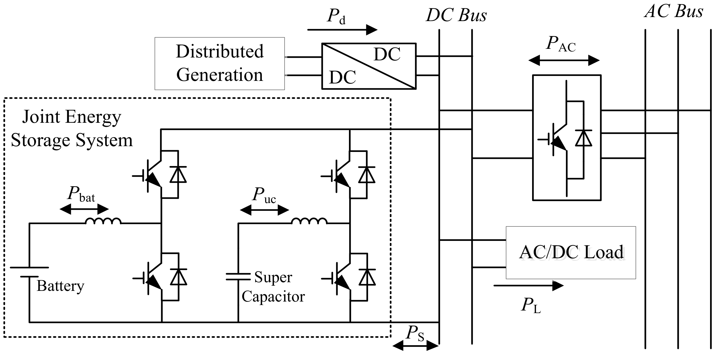
3.3.1. The Architecture of the Energy Storage System

Energy storage system with fast response is needed in microgrid to stabilize the power fluctuation caused by distributed generation and load switching. At the same time, it can ensure power quality and improve operational reliability. A single energy storage device cannot meet the requirements of large capacity and fast response. Therefore, the Hybrid Energy Storage System (HESS) has attracted a lot of attention when applied to the microgrid.
This paper designs a hybrid energy storage system composed of a battery and a supercapacitor connected to the DC bus side of simultaneous AC–DC hybrid microgrid and its corresponding control strategy, which can be used to balance the internal power fluctuation of the microgrid and suppress the fluctuation of the DC bus voltage [28].
The battery and supercapacitor have a variety of combinations [29]. This paper uses a parallel structure which has good flexibility and reliability, as shown in Figure 7.
The exchange power of hybrid energy storage device and DC bus is PS. The direction of flow to DC bus is positive. The PAC is the exchange power between the AC–DC bus and the DC bus. Pd and PL are the distributed generation power and load absorbing power, respectively. DC bus power balance can be expressed as
P S = P L P d P AC
The distributed generation generally works at the maximum output power point, so the degree of freedom of the Pd variation in the expression is low. The power difference caused by the load absorbed power and the transmission power of the AC–DC connecting line can only be balanced by the hybrid energy storage device.
An energy control strategy based on the power fluctuation dynamics can realize independent control of the storage battery and the supercapacitor. The DC bus power fluctuation is effectively suppressed and the DC bus voltage stability is controlled.

3.3.2. Energy Storage System Control

The operation control principle of the hybrid energy storage system is shown in Figure 8. The current controller collects the discharge voltage Usc and the current value Isc of the supercapacitor. Combining the high-frequency component PLh of the load changing collected by the power high-frequency monitor, we can calculate the current value and control the supercapacitor discharge power to achieve buffering support of supercapacitors for the high frequency load variation. The voltage regulator controller, which compares the actual voltage Udc of the DC bus with the reference voltage value Udcref, controls the battery bidirectional DC–DC converter to work in the voltage stability state, thereby achieving stable control of the DC bus voltage.
The charge controller collects the charge–discharge state quantity and the state of charge (SOC) of supercapacitors and storage battery. The storage battery is charged with constant voltage and limited current when the over discharge storage battery cannot achieve the constant voltage support for the DC bus. Since the capacity of the supercapacitor is small, when the high-frequency variation of the load is small, it is necessary to charge the supercapacitor with constant voltage and limited current, so that the supercapacitor can always maintain the ability to suppress high-frequency components of the load change.
The DC bus acts as a power exchange and voltage stabilization node. When the microgrid loses support from the main grid, the power fluctuations caused by distributed generation and load can be suppressed by the hybrid energy storage system.

4. Hybrid Microgrid Power Router

The simultaneous AC–DC power distribution system provides a grid-connected interface for a large number of distributed generations, making it possible for local consumption of distributed generation. This chapter proposes a modular multi-interface power router to realize the integrated control of the distribution system.

4.1. The Structure of Power Router

The simultaneous AC–DC hybrid microgrid is connected to distributed generations, energy storage systems, AC loads, and DC loads. The energy routing and mutual support between the AC microgrid and the DC microgrid must be achieved simultaneously. This paper builds the power router architecture with three-phase H-bridge and dual-active DC–DC converters as the core, as shown in Figure 9.
The power router is composed of a DC bus derived from the neutral point of the zigzag transformer and an AC bus derived from the secondary side. The DC bus and the AC bus are connected through the isolation module and inverter module. The inverter (rectifier) module realizes bidirectional power flow controllable. The isolation module ensures the independence between AC and DC systems.

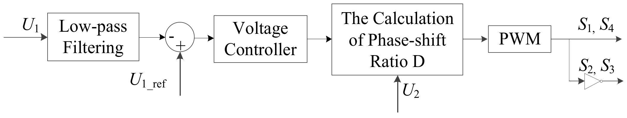
4.2. DAB and its Control

As shown in Figure 10, the DAB structure is composed of two full-bridge circuits and high-frequency transformers, with high power density, bidirectional power transmission capability, and good isolation. The DAB structure is symmetrical and the control is relatively simple [30].
Since the dual-active conversion circuit can realize power bidirectional transmission, port 1 and port 2 are input ports and output ports for each other.
When the microgrid works in networking mode, the DC voltage of port 1 needs to be stable within a certain range to ensure the power balance and voltage stability of the DC system. When the microgrid is operating in the islanding mode, the DC system is used as the power supply on the AC side, and the active power flow of ports 1 to 2 must be controlled according to the active power of the load on the AC side.
As can be seen from Figure 10, the dual-active DC–DC converter serves as an intermediate transmission link of the power router and mainly performs the isolation and power transmission tasks; it also supports the stability of the DC bus network in networking mode. In order to reduce the complexity of the power router control, its control objectives can be simplified: In the networking mode, the output voltage of the control port 1 is Up, that is, the voltage of the DC bus is stable and, in the islanding mode, the output voltage Us of the control port 2 meets the requirements of DC side voltage for three-phase H-bridge. The control principle of the dual-active DC–DC converter is shown in Figure 11.
The three-phase H-bridge DC voltage Us of the networked mode is determined, and the stable control of the voltage UP can achieve the control of the transmission power of the conversion circuit. Up is stable in the islanding mode while the control target of Us is given by the three-phase H-bridge. The use of a low-pass filtering device is to reduce the influence of high-frequency fluctuation components of the output voltage on the response characteristics of the control system.

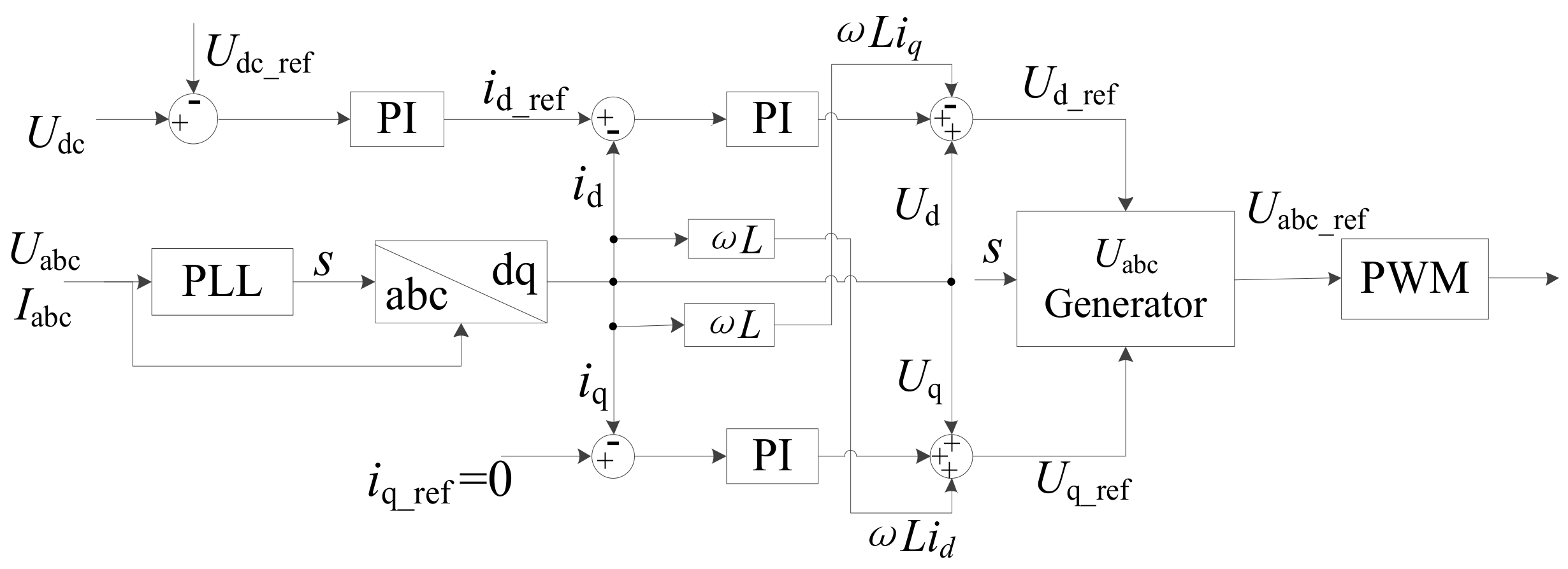
4.3. Three-Phase H-bridge AC–DC Converter and Its Control

The main circuit structure of the three-phase H-bridge AC–DC converter is shown in Figure 12 [31]. The three H-bridges are cascaded and the AC side is connected to the LC filter. Udc is the voltage of DC side. It can be seen from the main circuit structure of the power router that the AC output is connected to the AC bus and the DC terminal is connected to the DAB port 2.
The DAB’s control analysis shows that port 1 of the DAB is directly connected to the DC bus, whereas the DC-link output of the three-phase H-bridge directly determines the voltage level of the DAB port 2. Therefore, maintaining the voltage level of the DAB port 2 at this time is a control objective of the three-phase H-bridge in the networking operation mode of the power router.
According to the control objectives in the networking mode, the PQ control method based on active and reactive power structure control will be improved. The double closed-loop control structure is adopted. The external-loop voltage control provides reference quantity for the inner-loop current control. The inner-loop current control increases the control response speed, and at the same time, the current decoupling is realized by the current feed-forward. The reactive current control component is taken as 0. The reference value of the DC bus voltage is used as the reference value of the active component in the PQ control. The complete improved PQ control method is shown in Figure 13.
Phase-locked loop (PLL) uses the AC bus phase voltage and phase current measured by the system to obtain the phasing information s; the DC bus voltage reference amount is used instead of the active power reference amount, and the reactive current the reference iq_ref is 0. Combining the phase information with the reference of the active and reactive voltage (Ud_ref and Uq_ref), we can obtain the reference value of the AC bus voltage (Uabc_ref). The control signal of the inverter by the pulse width modulation (PWM) can also be obtained.
In the microgrid islanding mode, the three-phase H-bridge energy flows from the DC side to the AC bus and supplies power to the AC side load. At this time, the AC bus is equivalent to the load, and the AC bus voltage and frequency need to be kept stable. The three-phase H-bridge inverter adopts V/f control. The basic block H-bridge diagram of V/f control is shown in Figure 14.
The output frequency f of the phase-locked loop is compared with the reference frequency of the system. The active reference amount formed through the PI link is compared with the active power P of the system to obtain the reference value id_ref of the active current loop. The reference amount of reactive current is 0, and the reference values of the active voltage and reactive voltage are obtained through calculating. PWM control is used to obtain three-phase H-bridge control signals.

5. Simulation Analysis

In order to verify the rationality of the proposed simultaneous AC–DC hybrid microgrid and its power router, and the effectiveness of the corresponding control strategy. In this paper, the simultaneous AC–DC hybrid microgrid, shown in Figure 5, and the control model of the power router, shown in Figure 10, are built on the 2016 version of the MATLAB/Simulink simulation platform. Photovoltaic power generation and its control circuits, and hybrid energy storage devices and its control units are built. The power router adopts the first-level DAB and three-phase H-bridge cascaded main circuit structure. The main simulation parameters of the simultaneous AC–DC hybrid microgrid are shown in Table 1. In operation of the microgrid, the mixed energy storage capacity and its control parameters should be set according to the grid operation parameters.

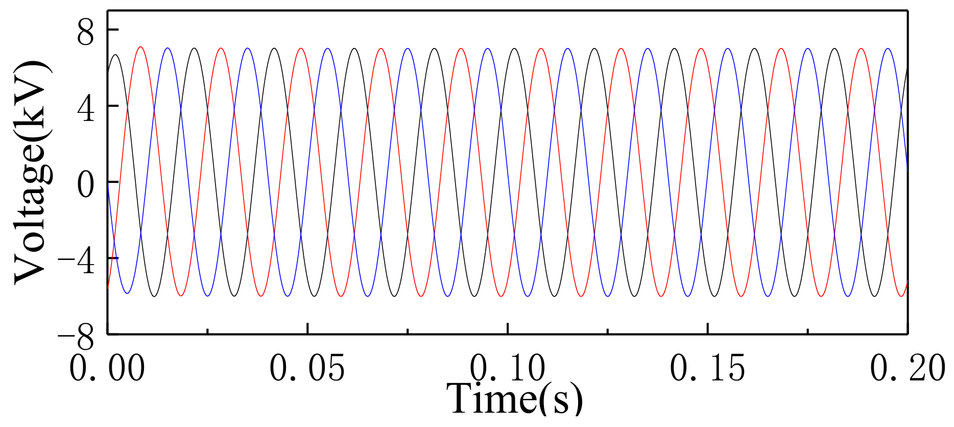
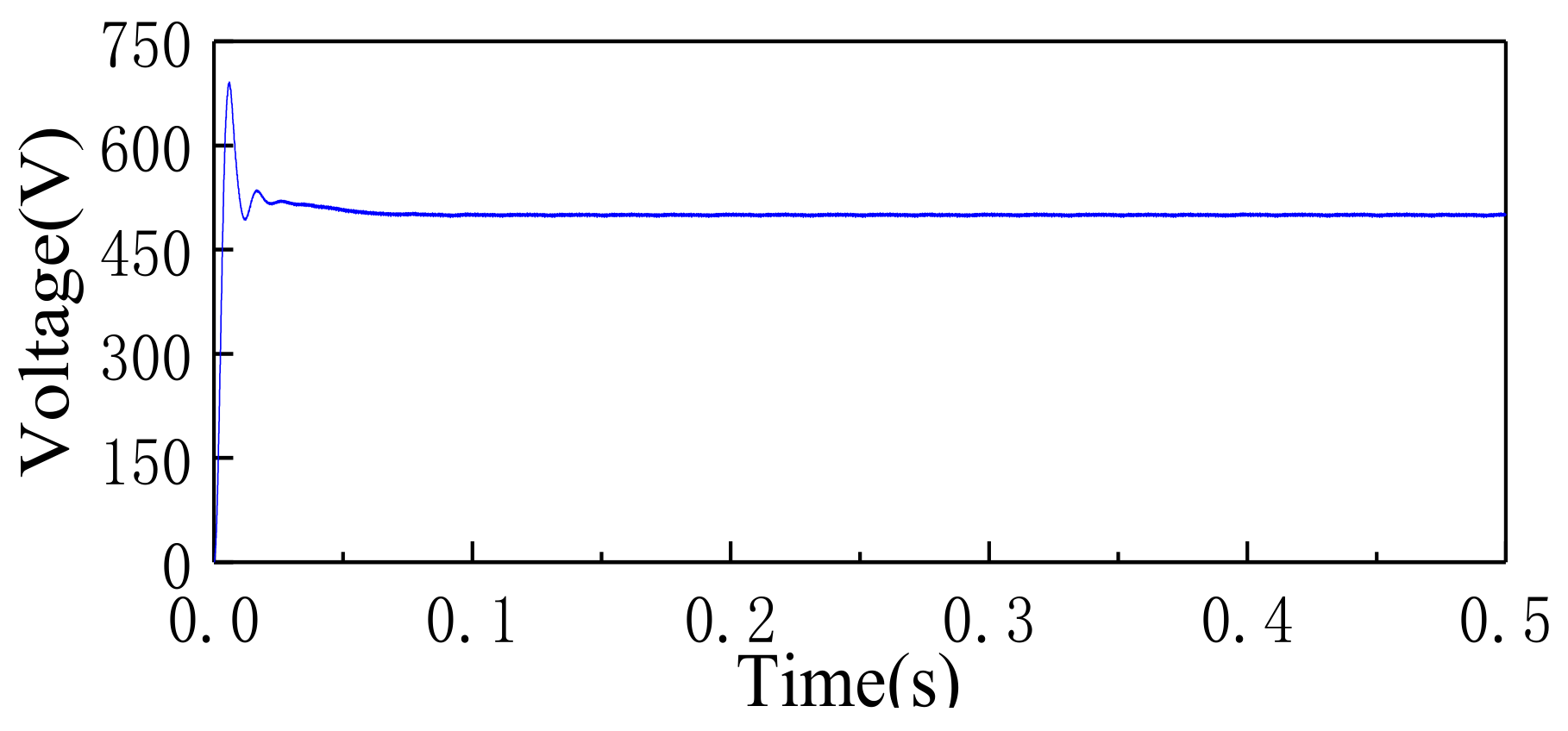
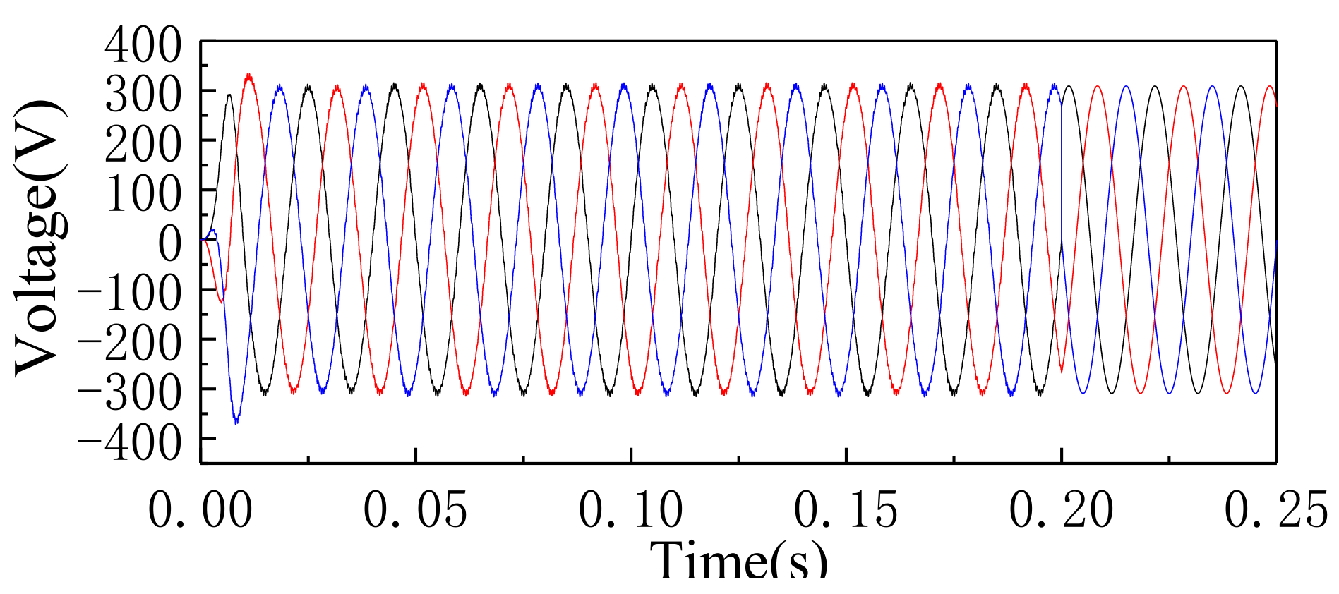
5.1. Three-Phase H-bridge AC–DC Converter and Its Control

The microgrid is started in a grid-connected mode when the photovoltaic power generation is at a temperature of 25 °C and an illumination intensity of 1000 kW/m2. The DC load is set to 50 kW. As shown in Figure 15, the photovoltaic power generation is rapidly stable at 100 kW, reflecting that the MPPT controller based on the incremental conductance method has good MPPT performance; at the same time, the distributed generation surplus power is transmitted to the main grid through a bidirectional inverter. The transmission power of the three-phase H-bridge AC–DC converter (bidirectional inverter) from the DC side to AC side is 50 kW, which ensures full use of distributed generation under the premise of stable operation of the system.
Figure 16 shows the three-phase voltage waveforms of simultaneous AC–DC transmission. The figure shows that the single-phase line voltage superimposes the voltage value of the DC bus on the basis of the symmetrical AC voltage, and the voltage waveform still has a zero-crossing point.
As shown in Figure 17 and Figure 18, the line voltage of AC bus voltage is 380V and the DC bus voltage is stable at 500 V. It shows that the power router can stabilize the DC bus voltage under the steady-state operating conditions of the networked operating mode.
Between 0.6 s and 1.1 s, the illumination intensity of photovoltaic panels is reduced linearly from 1000 kW/m2 to 250 kW/m2. The illumination intensity recovers to 1000 kW/m2 between 1.2 and 1.7 s. Between 0.7 s and 2 s, the temperature decreases from 25 °C to 15 °C and then returns to 25 °C. At 1 s, the DC load suddenly increased by 25 kW. At 1.5 s, the DC load recovered to 50 kW.
As shown in Figure 19, take the bidirectional inverter flow from AC side to DC side as positive energy flow direction. Under the operating conditions of PV power fluctuation and DC load power variation, the main grid can maintain the internal power balance of the microgrid through bidirectional inverters. Figure 20 shows the current waveform on the AC side of the bidirectional inverter. It can be obtained from the graph that the current controller has a good unbalanced current tracking performance which adopts the decoupling principle.
Figure 21 shows that the DC bus voltage fluctuates less than 15 V when the load power suddenly changes. The distributed generation power process is basically stable at 500 V. The power router can achieve stable control of the DC bus voltage.

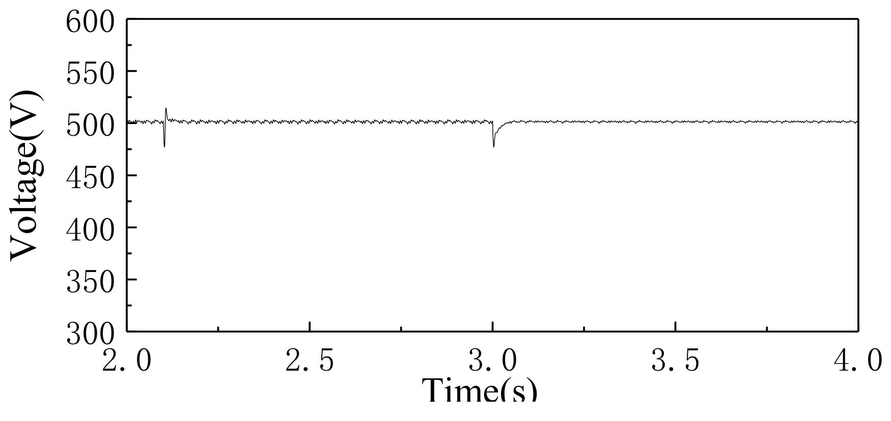
5.2. Microgrid Power Router Islanding and Mode Switching Simulation

The islanding mode lost the main grid support. In order to ensure the power supply of the load and maintain the stability of the AC–DC hybrid microgrid, the energy storage device works in the constant voltage control mode, and forms a combined power source of the hybrid microgrid with distributed power generation.
Simulation Scheme 1: At 2.1 s, the power router is disconnected from the grid-connected switch and the microgrid switch to the islanding mode. At this moment, the DC load was 50 kW and the AC load connected to the AC bus was 75 kW. The photovoltaic power generation has maximum power generation of 100 kW, and the AC load on the AC side suddenly increases by 25 kW at 2.4 s.
As shown in Figure 22, the hybrid energy storage system in the islanding mode outputs insufficient load power through the bidirectional DC–DC converter and controls the state to a stable DC voltage control. The supercapacitor quickly tracks the change of high frequency power when the load power step change occurs. And the output of the storage battery transits to the steady state operation smoothly.
As shown in Figure 23, the energy router can realize stable control of the DC bus voltage during mode switching, and the voltage fluctuation amplitude is lower than 25 V. At the same time, the fluctuation of the DC bus caused by the load power fluctuation in the islanding mode is lower than 30 V, which proves that the hybrid energy storage system can be used as the main power source to stabilize the DC bus voltage in the absence of external power supply.
Simulation Scheme 2: The microgrid is started in islanding mode. At this time, the power router controls the storage battery in a state of stable voltage control to stabilize the DC bus voltage; the bidirectional inverter is in the V/f control state to stabilize the AC bus voltage, so that it can ensure the supply of AC and DC loads. At 0.2 s, the grid-connected switch of the microgrid is closed and the microgrid is switched from islanding mode to grid-connected mode. Meanwhile, the bidirectional inverter is switched to the improved PQ control mode to stabilize DC bus voltage.
As shown in Figure 24, the AC bus line voltage is stable at 380 V, and the frequency is within the allowable range. After the islanding mode is switched to the networked operation, the phase of the AC bus voltage is quickly clamped to the main grid phase. The DC bus voltage fluctuates less than 40 V and then quickly transits to steady operation state as shown in the Figure 25.

6. Conclusions

Based on the change of energy utilization mode and the development trend of distribution network in the future, the concept and schemes of the simultaneous AC–DC hybrid microgrid and its power router are put forward. Some problems of the microgrid structure are studied. The conclusions are as follows.
  • The concept of microgrid is introduced into the simultaneous AC–DC power distribution scheme. For the structural characteristics of AC–DC hybrid microgrid, the structure and control strategy of the power router for hybrid microgrid are proposed. DC power injection with a Z-type transformer avoids saturation of transformer cores caused by DC current. The independence between the AC and DC systems is ensured while ensuring AC and DC power are transmitted simultaneously.
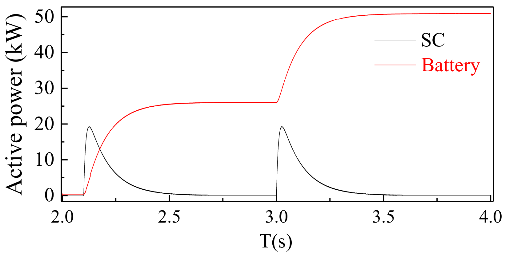
  • The simultaneous AC–DC power distribution system can set up an independent DC bus through DC injection and decoupling devices. Using this structure, a hybrid microgrid structure based on simultaneous AC–DC transmission is built. Distributed generation can achieve grid-connected operation through single-stage power conversion, simplifying the grid-connected structure and control methods. A hybrid energy storage system combining supercapacitor and storage battery is designed for the grid connection characteristics of new energy generation. The supercapacitor in the hybrid energy storage system can suppress the high-frequency components of the power fluctuation, and the storage battery realizes the balance of the internal energy of the microgrid.
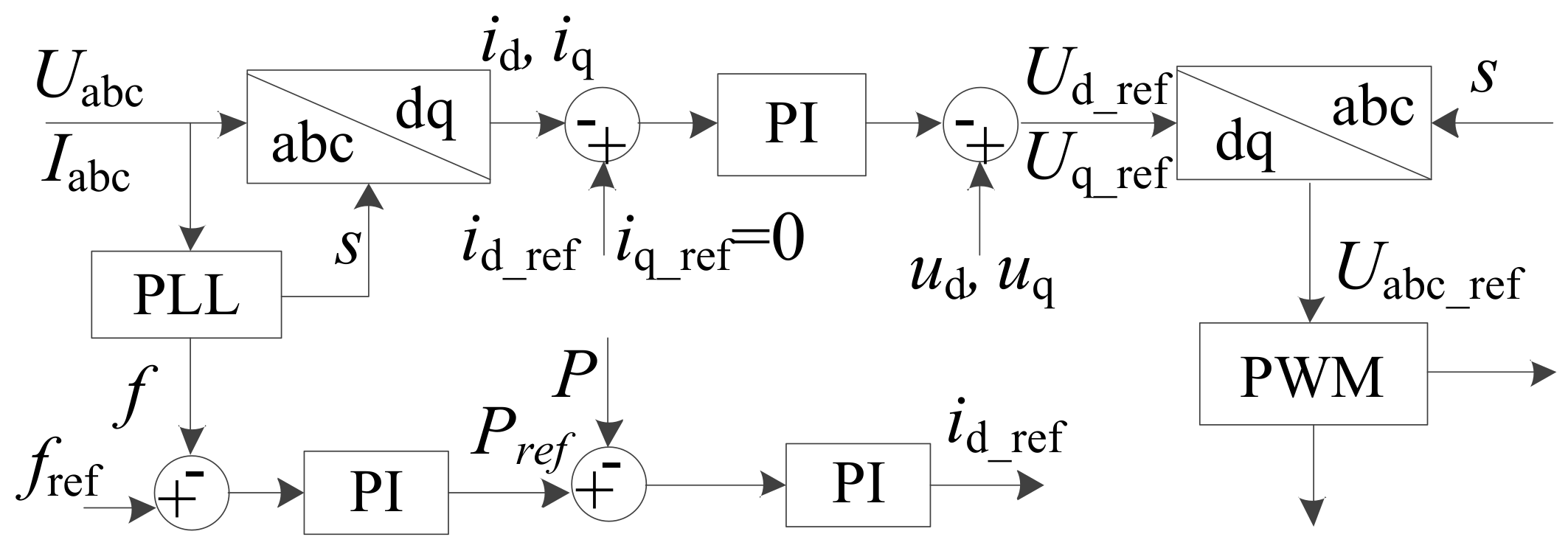
  • The modular multi-interface power router topology, an improved PQ control principle and a specific control strategy of the energy router based on the distributed autonomous principle are proposed. The simulation results show that the power router can realize energy routing function in various operating modes of the microgrid; it also can realize the internal power balance of the microgrid and ensure the stability of the microgrid bus voltage level.

Author Contributions

Investigation, X.G. and Y.W.; Methodology, X.G.; Project Administration, L.Z.; Software, Y.W.; Writing—Original Draft, X.G.; Writing—Review & Editing, R.C. and L.Z.

Funding

This research received no external funding.

Conflicts of Interest

The authors declare no conflicts of interest.

References

  1. Zhou, X.; Lu, Z.; Liu, Y.; Chen, S. Development Models and Key Technologies of Future Grid in China. Proc. CSEE 2014, 34, 4999–5008. [Google Scholar]
  2. Liu, Z. Electric Power and Energy in China; China Electric Power Press: Beijing, China, 2012; p. 174. [Google Scholar]
  3. Zong, S.; He, X.; Wu, J.; Li, W.; Zhao, R. Overview of power electronics based electrical energy router. Proc. CSEE 2015. [Google Scholar] [CrossRef]
  4. Cao, J.; Meng, K.; Wang, J.; Yang, M.; Chen, Z.; Li, W.; Lin, C. An energy internet and energy routers. Sci. Sin. (Inf.) 2014, 44, 714–727. [Google Scholar]
  5. Dong, Z.; Zhao, J.; Wen, F.; Xue, Y. From smart grid to energy internet: Basic concept and research framework. Autom. Electr. Power Syst. 2014, 38, 1–11. [Google Scholar]
  6. Ma, Z.; Zhou, X.; Shang, Y.; Sheng, W. Exploring the concept, key technologies and development model of energy internet. Power Syst. Technol. 2015, 39, 3014–3022. [Google Scholar]
  7. Bui, N.; Castellani, A.P.; Casari, P.; Zorzi, M. The internet of energy: A web-enabled smart grid system. IEEE Netw. 2012, 26, 39–45. [Google Scholar] [CrossRef]
  8. Han, Y.; He, Q.; Zhao, Y.; Guo, Z.; Yao, S.; Li, L. Access mode of intelligent distribution network to ac network based on flexible dc technology. Autom. Electr. Power Syst. 2016, 40, 141–146. [Google Scholar]
  9. Song, G.; Tao, R.; Li, B. Survey of Fault Analysis and Protection for Power System with Large Scale Power Electronic Equipments. Autom. Electr. Power Syst. 2017, 41, 2–12. [Google Scholar]
  10. Liu, Y.; Wu, Z.; Tu, Y.; Huang, Q.; Luo, H. A Survey on Distributed Generation and Its Networking Technology. Power Syst. Technol. 2008, 15, 71–76. [Google Scholar]
  11. Rifkin, J. The third industrial revolution: How lateral power is transforming energy, the economy, and the world. Survival 2011, 2, 67–68. [Google Scholar]
  12. Lasseter, R.H. MicroGrids. IEEE Power Eng. Soc. Winter Meet. 2002, 1, 305–308. [Google Scholar]
  13. Hatziargyriou, N.; Asano, H.; Iravani, R.; Marnay, C. Microgrids. Power Energy Mag. 2007, 5, 78–94. [Google Scholar] [CrossRef]
  14. Song, Q.; Zhao, B.; Liu, W.; Zeng, R. An Overview of research on smart dc distribution power network. Proc. CSEE 2013, 33, 9–19. [Google Scholar]
  15. Wang, C.; Xiao, Z.; Wang, S. Synthetical control and analysis of micro-grid. Autom. Electr. Power Syst. 2008, 32, 98–103. [Google Scholar]
  16. Koichiro, T. Application and economical evaluation of the superposed AC and DC power transmission system. Electr. Eng. Jpn. 2010, 98, 114–120. [Google Scholar]
  17. Rahman, H.; Khan, B.H. Enhanced power transfer by simultaneous transmission of AC–DC: A new facts concept. IET Power Electron. Mach. Drives 2004, 1, 186–191. [Google Scholar]
  18. Andreotti, A.; Lauria, D.; Mottola, F. Optimal design of combined AC–DC transmission lines. In Proceedings of the IEEE International Symposium on Power Electronics, Electrical Drives, Automation and Motion, Ischia, Italy, 11–13 July 2008; pp. 411–415. [Google Scholar]
  19. Lucas, R.; Pahalawaththa, N.; Annakkage, U.; Boys, J. Ac-Small power dc hybrid transmission for improving power system stability. Electr. Power Syst. Res. 2000, 56, 9–15. [Google Scholar] [CrossRef]
  20. Weimers, L. HVDC Light: A New Technology for a Better Environment. IEEE Power Eng. Rev. 1998, 18, 19–20. [Google Scholar] [CrossRef]
  21. Gopiya Naik, S.; Khatod, D.K.; Sharma, M.P. Distributed generation impact on distribution networks: A review. In Proceedings of the 2011 International Conference on Advanced Power System Automation and Protection, Beijing, China, 16–20 October 2012; Volume 2. [Google Scholar]
  22. Cui, X.; Yu, J. The way of AC and DC transmitting simultaneously along the same feeder line in distribution network. Proc. CSEE 2007, 11, 6–11. [Google Scholar]
  23. Zhang, L.; Wu, H.; Cao, L.; Li, Q.; Zhao, T.; Zou, L. Simulation analysis on zigzag transformer-based AC–DC combined distribution network automation of electric power system. Autom. Electr. Power Syst. 2014, 38, 79–84. [Google Scholar]
  24. Zhang, L.; Liu, M.; Zhao, T. Application of intelligent inductive filtering in the technology of combining AC–DC power transmission along the same line for distribution network. Power Syst. Technol. 2015, 39, 2371–2376. [Google Scholar]
  25. Xu, X.; Tai, N.; Fan, C.; Zheng, X. Scheme study on simultaneous AC–DC distribution network. Power Syst. Technol. 2016, 40, 2120–2128. [Google Scholar]
  26. Hao, D. Study of AC plus DC Distribution Network Suitable for Distributed Generation Connection; Shandong University: Ji’an, China, 2016. [Google Scholar]
  27. Ke, G.; Yi, L.; Zhou, S.; Wang, S.; He, D. Study of capacity-increase for simultaneous AC–DC transmission based on double circuit AC transmission line. Power Syst. Prot. Control 2013, 41, 25–31. [Google Scholar]
  28. Basu, K.P.; Khan, B.H. Simultaneous AC–DC power transmission. J. Inst. Eng. (India) Electr. Eng. Div. 2001, 82, 32–35. [Google Scholar]
  29. Dougal, R.A.; Liu, S.; White, R.E. Power and life extension of battery-ultra capacitor hybrids. IEEE Trans. Compon. Packag. Technol. 2002, 25, 120–131. [Google Scholar] [CrossRef]
  30. De Doncker, R.W.; Divan, D.M.; Kheraluwala, M.H. A three-phase soft-switched high power density DC/DC converter forhigh power applications. IEEE Trans. Ind. Appl. 1991, 27, 63–73. [Google Scholar] [CrossRef]
  31. Mi, C.; Bai, H.; Wang, C.; Gargies, S. Operation, design and control of dual H-bridge-based isolated bidirectional DC–DC converter. IET Power Electron. 2008, 1, 507–517. [Google Scholar] [CrossRef]
Figure 1. The single-loop structure of simultaneous AC–DC distribution network.
Energies 12 01077 g001
Figure 2. Zigzag transformer DC injection.
Energies 12 01077 g002
Figure 3. Voltage vector diagram of secondary side winding of type Z transformer2.2. DC Injection Rules.
Energies 12 01077 g003
Figure 4. Single phase-to-ground voltage waveform of two systems.
Energies 12 01077 g004
Figure 5. Unipolar simultaneous AC–DC hybrid microgrid structure.
Energies 12 01077 g005
Figure 6. Simplified structure diagram of microgrid.
Energies 12 01077 g006
Figure 7. Hybrid Energy Storage System Basic Structure.
Energies 12 01077 g007
Figure 8. Hybrid energy storage system control strategy.
Energies 12 01077 g008
Figure 9. Power router structure based on power electronic device.
Energies 12 01077 g009
Figure 10. Dual-active DC–DC Converter.
Energies 12 01077 g010
Figure 11. The control of dual-active DC–DC converter.
Energies 12 01077 g011
Figure 12. Three-phase H-bridge main circuit.
Energies 12 01077 g012
Figure 13. Three-phase bridge control structure in networked mode.
Energies 12 01077 g013
Figure 14. Three-phase H-bridge control structure in islanding mode.
Energies 12 01077 g014
Figure 15. Output power.
Energies 12 01077 g015
Figure 16. Simultaneous AC–DC transmission voltage.
Energies 12 01077 g016
Figure 17. DC bus voltage.
Energies 12 01077 g017
Figure 18. AC bus voltage.
Energies 12 01077 g018
Figure 19. Power change of microgrid.
Energies 12 01077 g019
Figure 20. Inverter three-phase current.
Energies 12 01077 g020
Figure 21. DC bus voltage.
Energies 12 01077 g021
Figure 22. Output power of the energy storage device.
Energies 12 01077 g022
Figure 23. DC bus voltage.
Energies 12 01077 g023
Figure 24. AC bus voltage.
Energies 12 01077 g024
Figure 25. DC bus voltage.
Energies 12 01077 g025
Table 1. Microgrid simulation parameters.
Simulation ParametersValue
Feeder AC Line Voltage8 kV
Microgrid AC Bus Line Voltage380 V
DC Bus Voltage500 V
Photovoltaic Generator Rated Voltage274 V
Photovoltaic Generator Rated Power100 kW
Rated DC Load50 kW
Important AC Load75 kW
Secondary AC Load25 kW
Storage Battery Capacity300 Ah
Storage Battery Rated Voltage250 V
Supercapacitor Capacity50 Ah
Supercapacitor Rated Voltage250 V

