Article

Thermal Stress and Cyclic Stress Analysis of a Vertical Water-Cooled Wall at a Utility Boiler under Flexible Operation

1
School of Energy, Power and Mechanical Engineering, National Thermal Power Engineering & Technology Research Center, Key Laboratory of Condition Monitoring and Control for Power Plant Equipment of Ministry of Education, North China Electric Power University, Beijing 102206, China
2
Department of Security, Environment Protection and Supervision, National Energy Investment Group Co. Ltd., Beijing 10085, China
*
Author to whom correspondence should be addressed.
Energies 2019, 12(6), 1170; https://doi.org/10.3390/en12061170
Submission received: 11 January 2019 / Revised: 21 March 2019 / Accepted: 22 March 2019 / Published: 26 March 2019
(This article belongs to the Section F: Electrical Engineering)

Abstract

:
Supercritical once-through utility boilers are increasingly common in flexible operations in China. In this study, the tube temperature changes at a vertical water-cooled wall are analyzed during a fluctuating flexible operation. There are considerable differences in the temperatures of the parallel tubes at the minimum load, and the resulting thermal stress distributions at a front water-cooled wall are established using structural calculation software ANSYS 17.1, USA. A wide thermal stress distribution occurs among the parallel tubes, and the local cyclic stress amplitudes under flexible operation are higher than those under cold, warm, hot, or load-following operations. Because of the water wall expansion structure at the furnace, the higher tube temperature areas suffer from compressive stress, while the lower tube temperature areas suffer from tensile stress. During flexible operation, combustion uniformity and a two-phase flow distribution can improve the safety of vertical water-cooled wall operation. The minimum load of the utility boiler should be set as a limitation, and the tube temperature is an important parameter affecting the thermal and cyclic stresses.

1. Introduction

Because of the penetration of renewable energy in the power grid, the fluctuations in the residual load of the power grid have been increasing for fossil fuel power plants. The power grid requires a flexible power system to provide backup capacity for longer periods with little variable renewable energy source (RES) feed-in [1]. The operational flexibility requirements on fossil fuel power plants demanded from variable RESs are as follows: (1) Increasing the ramp rate; (2) reducing the minimum load; (3) decreasing the efficiency losses for part-load operations; and (4) maintaining the safety of pressured components and environmental requirements [2]. In the next 10 years, the power system in certain areas of China may suffer a similar situation as in Europe as the power output from fossil fuel power plants continues to decline and the renewable energy penetration into the power grid continues to increase; this situation is exemplified by the 12% increase to 679 TWh from wind, solar, and biomass generation in 2017, putting wind, solar, and biomass above coal generation for the first time in Europe; just five years ago, coal generation was more than twice that of wind, solar, and biomass [3].
Flexible power generation is a new operational mode that can be used to secure reliable, affordable, and sustainable power production. The number of applications of a given degree of cyclic stress to which a component can be subjected before failure is known as the fatigue lifetime of the component. The minimum load of coal-fired utility boilers can reach at 25–40% BMCR (boiler maximum continuous rate), depending on the safety requirements of the utility boiler water circulation loop, the heating surface, and combustion stability under lower load [4].
Modliński pointed out that lower steam flow rates and poor heat dissipation conditions could result in tube rupture from the local overheating of the heat exchanger material during flexible operation. It is thus necessary to keep an eye on maintaining uniform temperatures of the tube metal at the heating surface of the utility boiler [5].
In 2001, EPRI (Electric Power Research Institute) researchers listed the problems arising from thermal cycling and low-load operation of fossil fuel plants caused by thermomechanical cycling of the tube attachments. The thermal fatigue lifetime can be estimated using ASME (American Society of Mechanical Engineering) fatigue design [6,7]. Researchers in Poland presented the problems of start-up for a utility boiler from the cold, warm, and hot states. The permissible heating and cooling rates of thick-walled components of the utility boilers, i.e., drums and the main steam outlet header were determined using European Standard EN 12952-3. A stress analysis of the maximum values of the circumferential, axial, and shear stresses during the operation cycle of the steam boiler was completed [8].
Engineers Canada discussed the low-cycle fatigue failures in tubes in proximity to the weld attaching the tubes to the header in economizers and superheaters of horizontal gas path (HGP) HRSGs (Heat Recovery Steam Generator) during start-ups and shutdowns. The tube temperature distribution along the parallel tubes at the header had a larger tube temperature difference during the transient process of start-up and shutdowns [9].
In most of the literature, the thermal stresses in thick-walled components such as headers and turbines are considered critical for flexible operation at large-scale power plants, but the tube metal at the heating surface of the water-cooled wall, superheater, and reheater is also important for safe and reliable operation [4,5,10,11,12]. The effect of cyclic load operation on the main pressured equipment and water circulation will suffer tube temperature fluctuations in a cyclic manner from thermal stress and fatigue [13]. With the large variations in the load, as per the requirement of the power grid, the wear and tear of the equipment also increases, ultimately affecting the reliability of the unit via thermal expansion. To date, no thermal stress and cyclic stress evaluation has been performed on a water-cooled wall at minimum load in a utility boiler that is operating under uneven combustion and flow distribution conditions because of the lack of data from a power plant under flexible operation [14,15,16,17,18,19].
As mentioned above, although it is crucial to understand the reliability and safety of the main heating surfaces of a utility boiler for flexible operation, little available studies have focused on the operation safety at the vertical water-cooled wall of a supercritical utility boiler. In this paper, the tube temperature distributions and differences among parallel tubes along four side water-cooled walls are discussed based on the operating data of the DCS (Distributed Control System) in a supercritical utility boiler under flexible operation. A two-dimensional mathematical model of the front water-cooled wall is proposed to simulate the generation of cyclic thermally induced stresses at the tube attachment using the finite element software ANSYS (17.1, ANSYS, Canonsburg, PA, USA). The thermal stresses and cyclic stress at the maximum stress position of the water-cooled walls are analyzed. The simulation provides a reference for the safe operation of a peaking power plant under low fluctuating loads.

2. Case Study of a Utility Boiler

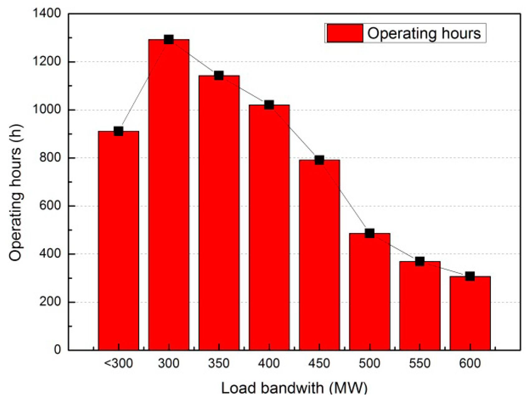
In Northeast China, several coal-fired power plants are already providing significant operational flexibility, adjusting their power output based on renewable energy feed-in and demand. Figure 1 shows the power output of a 2 × 600 MW peaking power plant from the years 2009 to 2016, during which the plant had a gradually decreasing annual power output. Because of the peaking operation, the load bandwidth during operating hours mainly remains in the range of 180 to 600 MW in this 600 MW power plant, as shown in Figure 2. As per the requirement of the ancillary services of the power grid, the operating hours at an ultralow load of less than 300 MW exceeds 900 h every year. From 21 January to 2 February 2017, the power generation unit worked at 180 MW, corresponding to 30% of the boiler maximum continuous rate (BMCR), for more than 10 days in this case study.

2.1. Parameters of the Utility Boiler

On the basis of the available utility boiler operation and design documentation, the main parameters of the utility boiler are listed in Table 1.
The utility boiler comprises a water-cooled dry-bottom furnace, a superheater, a reheater, an economizer, and air preheater components. The boiler is a Benson once-through utility boiler with single reheat, a recirculating pump, a dry ash discharge, a steel frame, a suspension structure, and double-pass and wall-fired combustion. The combustion systems consist of 30 low-NOX axial swirling burners (LNASBs) using a wall-fired layout. Six ZGM113G medium-speed pulverizers provide coal powder under the positive primary air system. This Benson boiler is a typical supercritical utility boiler widely used in the world. The design coal of this boiler is Shuang-ya-shan coal initially, after which the utility boiler switches to the use of blended coal, which is the design coal blended with lignite coal at different rates, depending on the operating load; lignite coal is exclusively used at the minimum load under flexible operation.

2.2. Water-Cooled Wall Structure of the Utility Boiler

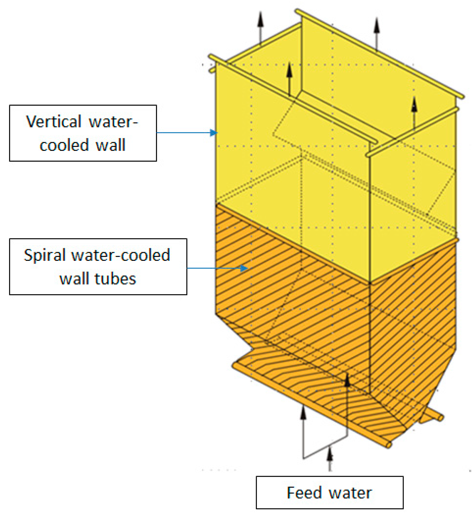
Figure 3 shows the spiral and vertical water-cooled wall of the supercritical 600 MW pulverized coal unit furnace for variable pressure operation. The sloped tube, angled at 17.893° from horizontal, wraps around the lower furnace in a single pass (spiral wound construction). At a point below the furnace nose, the furnace tubes transition to a vertical tube arrangement for the lower heat flux zone of the upper furnace. The membrane panels are composed of tube rows spaced on the centers wider than a tube diameter and are joined by a membrane bar securely welded to adjacent parallel tubes, which are the main topic of concern of this study.
To measure the uniformity among parallel tubes in flow circuits, the tube temperature thermocouples are installed at the outer wall of the spiral and vertical water-cooled wall every three to seven parallel tubes. Those thermocouples are calibrated periodically by maintenance technicians. The vertical water-cooled wall geometrical structure and parameters are listed in Table 2.
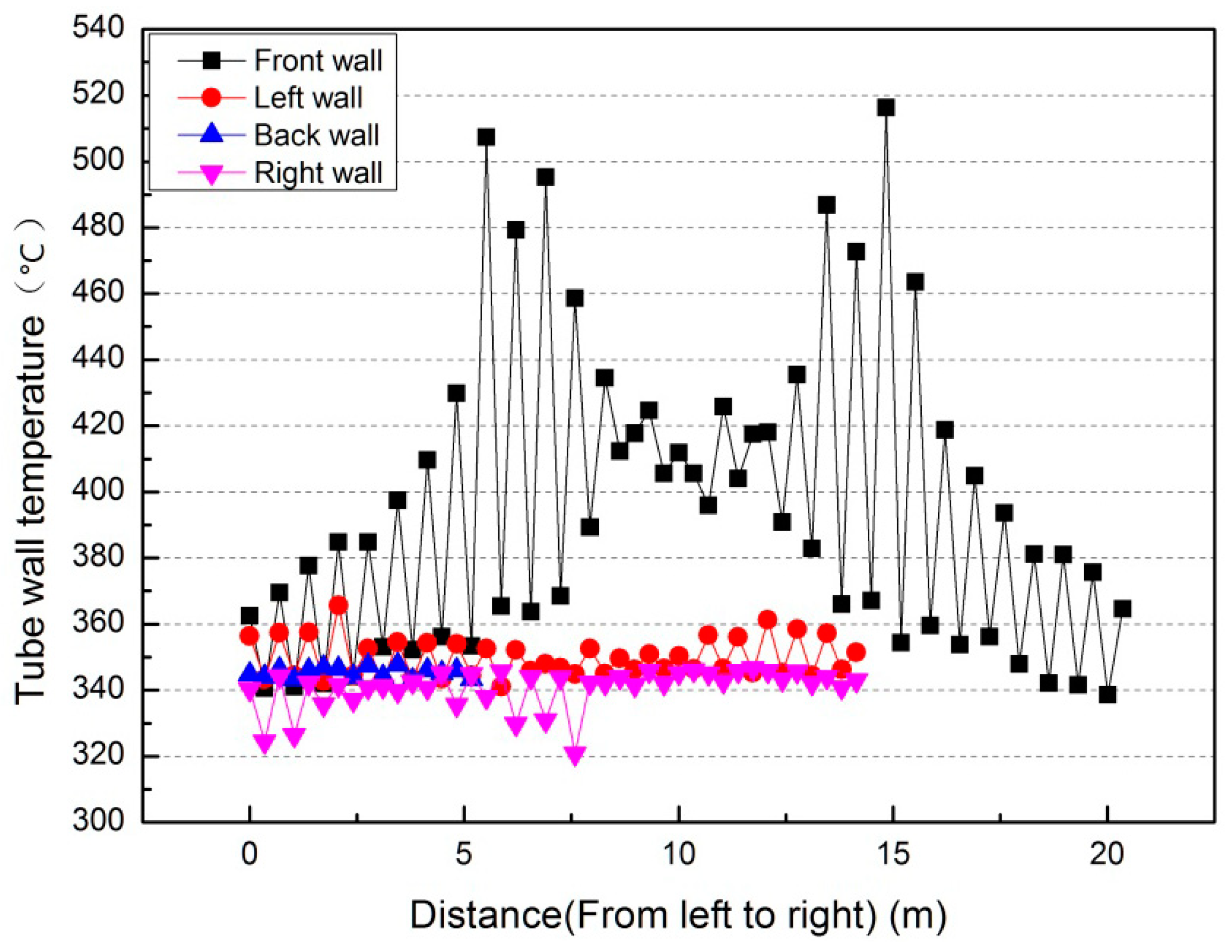
On the basis of the operating data provided from the power plant, when the boiler is operated at the minimum load for a long period of time, a high tube temperature exists in the width direction at the front wall, as shown in Figure 4. An instance of the maximum tube temperature distribution along the vertical water-cooled wall of four walls is chosen and adopted inside the furnace during flexible operation under the minimum load. The highest tube temperature along the front wall occurs at this moment. Adjacent wall temperatures reach at the highest value along the front wall width from 5 m to 7.5 m and from 12.5 m to 17.5 m, as shown in Figure 4. At the left, back, and right walls, the tube temperatures maintain a relatively stable distribution below 340 °C. According to the operating data from the peaking power plant, large temperature fluctuations occur among the parallel tubes in the vertical water-cooled walls when the boiler remains under the minimum load of 180 MW for 13 days; in particular, in the front water-cooled wall of the boiler, the maximum temperature difference can reach nearly 160 °C at 15 m from left to right in Figure 4. These large temperature differences adversely impact the safe operation of the utility boiler. Further research studies on the impact of these temperature differences are urgently needed.

3. Data Reduction

3.1. Water-Cooled Wall Tube Temperature Variation and Temperature-Difference Distribution Analysis

To determine the tube temperature changes during the load fluctuation under operation, Figure 5 shows the water-cooled tube temperature distributions of 175 tube temperature measuring points at the front, left, back, and right vertical water-cooled wall for 13 days as the utility boiler remains under flexible operation.
As shown in Figure 5a, when the load is between 180 MW and 400 MW, the vertical tube temperatures at the front wall change considerably and fluctuate between 330 °C and 530 °C. When the load exceeds 400 MW, the tube temperatures fluctuate between 350 °C and 450 °C. The general temperature distribution trend is that as the load increases, the average temperature at each tube temperature increases and the temperature distribution range gradually decreases. Figure 5b shows the variation in tube temperature distribution at the left wall. When the load is between 180 MW and 350 MW, the tube temperatures fluctuates between 330 °C and 490 °C. This temperature distribution range is smaller than that at the front wall. When the load exceeds 350 MW, the tube temperature distribution range is below 450 °C. The overall variation trend of the left wall is consistent with that of the front wall. Figure 5c shows the change in the tube temperature distribution at the back wall. The temperature distribution increases with increases in the boiler load, and the temperature variation range is always maintained at 350 °C to 400 °C with the minimum temperature variation range among the four walls. Figure 5d shows the temperature variation at the right wall. The temperature increases with increases in the boiler load, and the tube temperature range is maintained in the range of 310 °C to 430 °C. The tube temperature range will fluctuate when the load ranges 300 MW to 400 MW, with the maximum temperature range being up to 120 °C.
Although Figure 5 shows the temperature fluctuations at the four sidewalls, the temperature differences at adjacent parallel tubes are not available. The adjacent tube temperature differences affect the thermal stress of the vertical water wall during flexible operation. Tube temperature differences are critical parameters for calculating the thermal stress. An equation is defined to evaluate the variation in the temperature differences during the operation as follows:
ΔT = Ti − Ti−1,
where ΔT—Tube temperature difference; Ti—Tube temperature thermocouple i; Ti−1—Tube temperature thermocouple i − 1; i—Tube temperature thermocouple number from left to right at one side water-cooled wall as 1, 2, 3, …
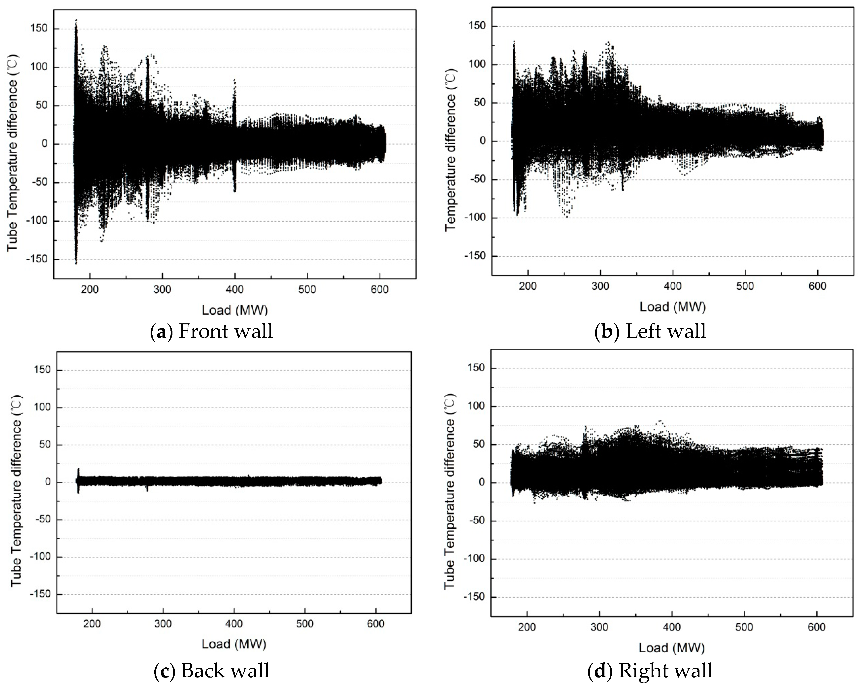
In Figure 6, the tube temperature difference (ΔT) distributions are given along the front, left, back, and right walls with changes in the boiler load. The temperature differences gradually decrease with increases in the boiler load. The temperature differences are higher at the front wall and left wall when the boiler load ranges from 180 MW to 350 MW; the maximum value of 160 °C appears at the front wall when the load is 180 MW. The temperature difference (ΔT) remains between 50 °C and 160 °C when the load is less than 300 MW, i.e., a large temperature difference occurs at loads of less than 50% BMCR; this temperature difference exceeds the allowable parallel adjacent tube temperature difference (50 °C) according to the utility boiler water wall design rules. The effect of the temperature difference on the vertical water wall is crucial for the safety of the water-cooled wall and must be further clarified and analyzed. As shown in Figure 6b, a large great temperature difference occurs at the left wall. For the back wall, the temperature difference is far less than 50 °C, as shown in Figure 6c. For the right wall, the temperature difference differs from those of the front wall and the left wall; the highest temperature difference does not exceed 80 °C and is far less than that of the front wall and left wall. The temperature differences generally remain lower than 50 °C at the right wall.
Figure 5 and Figure 6 show that the tube temperature differences at the front and left wall exhibit the largest fluctuations. According to the design rules for utility boiler vertical water walls, the adjacent vertical parallel tube temperature differences must be less than 50 °C, and the spiral parallel tube temperature differences must be less 80 °C. To maintain the safe operation of the vertical water wall, the thermal stress and cyclic stress at the vertical water wall areas under flexible operation must be analyzed.
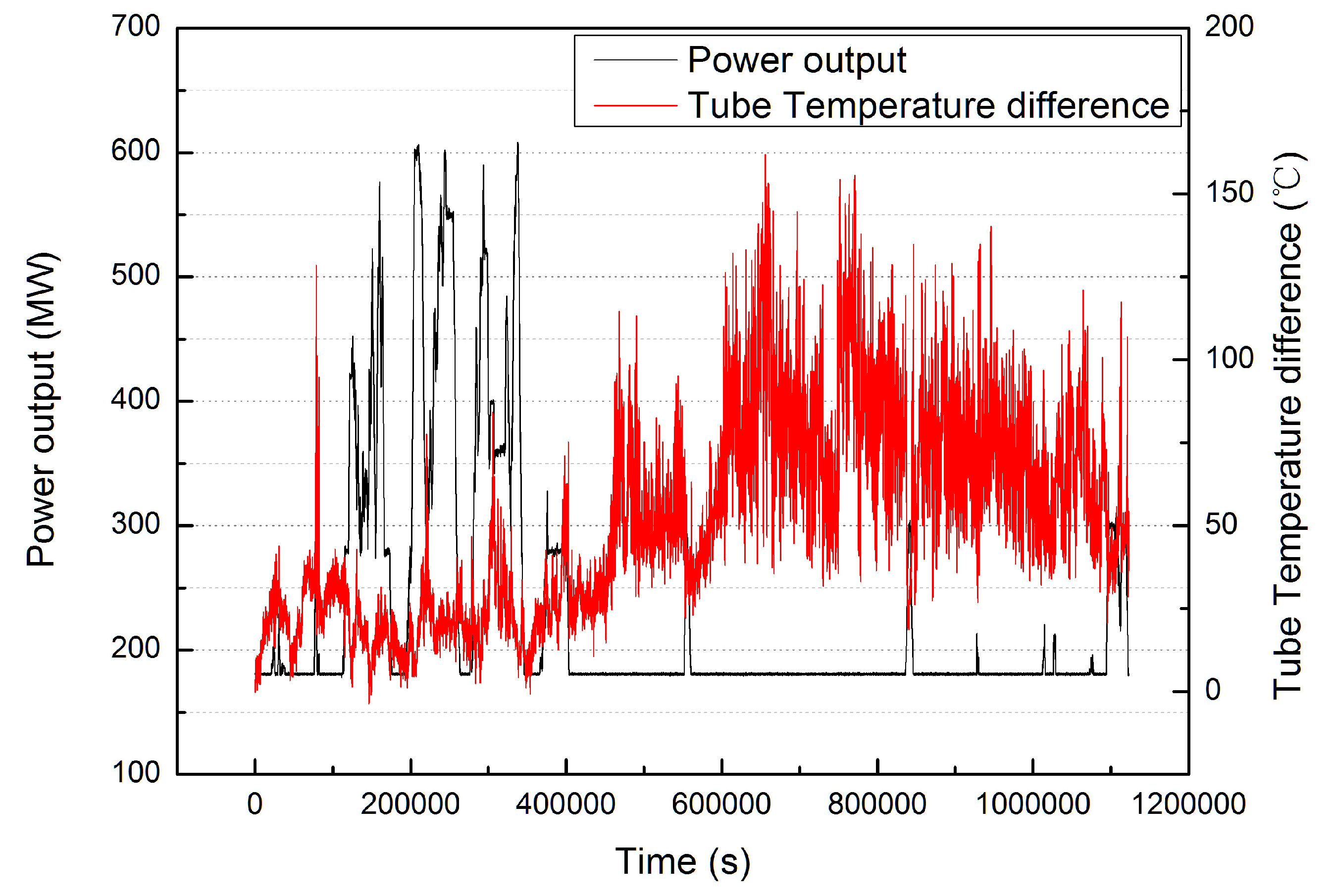
From Figure 7, the tube temperature differences are selected from the lowest load (180 MW) to the highest load (600 MW); the temperature differences fluctuate from approximately 30 °C to 160 °C. In this paper, the real-time data from 7–12 January 2017 are selected as the temperature boundary conditions and loaded into the ANSYS finite element model to calculate the effect of the long-term minimum operating load on the thermal and cyclic stresses of the front water-cooled wall.

3.2. The Reason for the Temperature Fluctuations at Front and Left Walls under Flexible Operation

Flexible operation is one of the stat-of-art researches of coal-fired power generation. The main research issues in current flexible boilers are how to reduce the minimum workload, increase the ramp rate, and increase the thermal efficiency of low loads. It is generally believed that the minimum load operation is mainly caused by two problems of low load combustion and low load hydrodynamic characteristics. According to the boiler manufacturer design regulation, temperature differences at adjacent parallel tubes in vertical water wall are less than 50 °C.
Through power plant experiments, it is found for the first time that thermal stress of the water-cooled wall is caused by the minimum load and long-term operation at the vertical water-cooled parallel tubes. This problem has not received sufficient attention from academic and industrial circles in the current papers on flexible operation at present. Therefore, the impact of this phenomenon on the two-phase flow distribution and lifetime of water wall are analyzed through two-phase flow experiment and the thermal stress of vertical water-cooled wall under flexible operation.
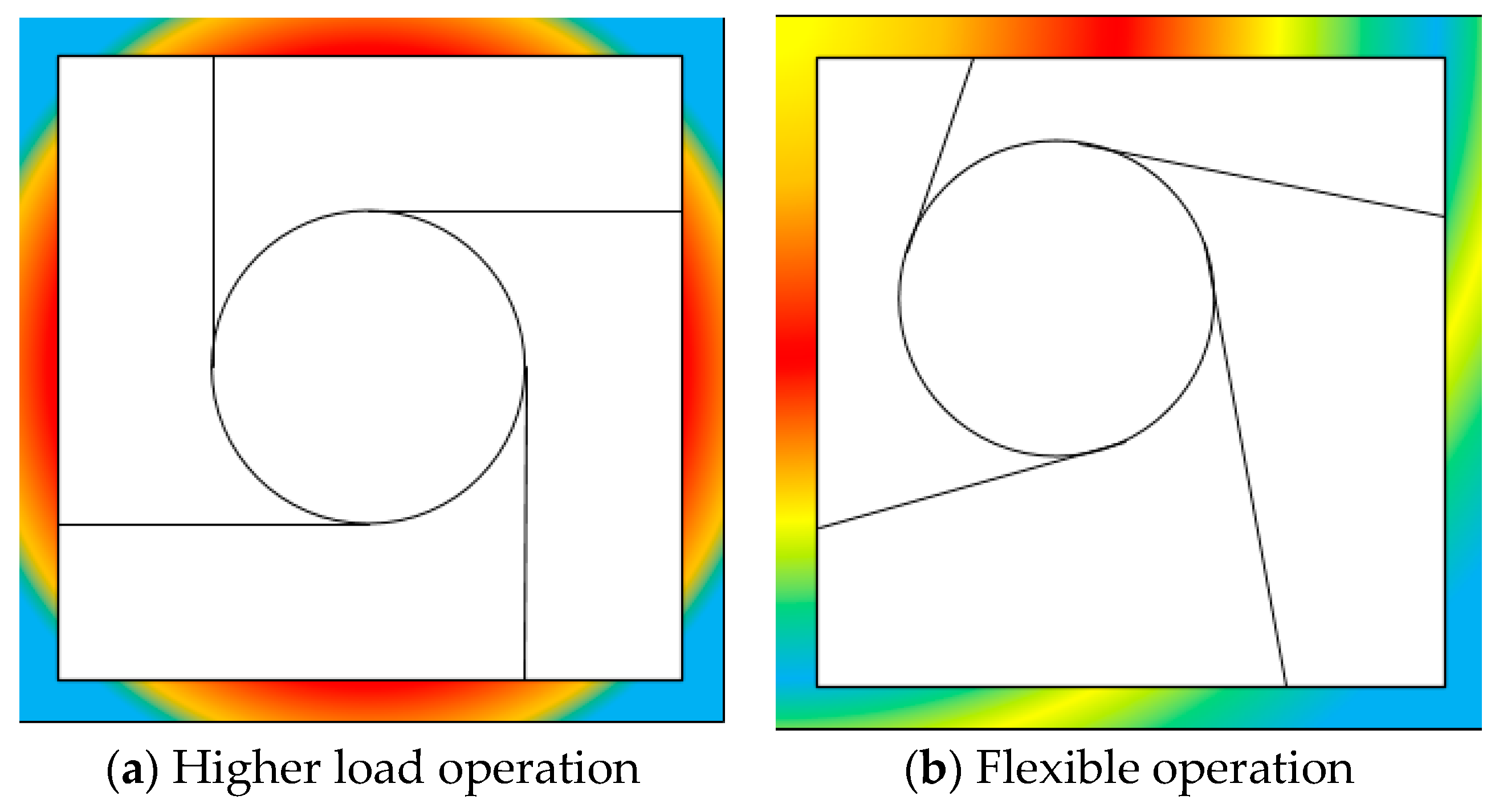
Why are the temperature fluctuations at the front and left walls so large in comparison to those of the other walls? Why are the temperature fluctuations higher at a low load? The front and left walls suffer from the highest heat flux distributions far from the average. The different heat flux distributions at the four sidewalls are demonstrated in Figure 8. That means that the combustion center deviates from its original position because of the fullness with flue gas during flexible operation at a low load in Figure 8b. The heat absorption at the front and left water-cooled walls is greater than that at the back and right wall. There is higher heat absorption, and less of the flow rate is distributed at the higher temperature wall. It is necessary to conduct two-phase flow distribution and thermal stress and cyclic stress analyses to evaluate the safety and reliability at this area.
At the uneven heat flux distribution, there is severe two-phase flow distribution under minimum working load under flexible operation. Because of uneven heat flux at parallel tubes of vertical water wall in intermediate header, there are different saturated steam velocities at parallel tubes at water wall. The droplets at intermediate header could not be carried by the saturated steam at different parallel tubes at vertical water wall. The water is accumulated at intermediate header, because the drain valves are closed under flexible operation. The two-phase flow distribution has been different from the normal operation.
In order to simulate the two-phase flow distribution at side wall in the minimum workload, the two-phase flow experiment is conducted at the water-cooled wall intermediate header under the minimum load. The two-phase flow distribution is seriously deviated, causing a huge two-phase flow deviation, and at this time, the boiler’s flame fullness is reduced during the minimum load, and the furnace heat flux at water-cooled wall is also seriously uneven. These two deviations superimpose the boiler vertical water wall tubes. The internal two-phase flow distribution is far from the normal design tolerance, causing the large temperature difference thermal stress damage at the vertical water wall tubes.
Gas or liquid flow ratio is defined as the ratio of the measured gas or liquid flow rate in certain parallel tubes over the average gas or liquid flow rate evaluated for uniform distribution. An equation is defined to evaluate the flow distribution in the parallel tubes at water wall intermediate header during the operation and the standard deviation coefficient (STD) is given to evaluate the uneven distribution of parallel tubes as follows:
β k , j = w k , j j = 1 N w k , j / N       ( k = g , l )
where β—gas or liquid flow ratio; w—gas or liquid mass flow rate at certain parallel tube j; N—the total amount of parallel tube numbers; k—gas or liquid phase, g-means gas phase, l means liquid phase; j—parallel tube number.
Gas and liquid flow ratios show the deviation of gas and liquid flow distribution at parallel tubes. The flow ratio is ideally 1, which means gas or liquid flow distribution equally at parallel tubes. Otherwise, the two-phase flow distribution becomes uneven. This coefficient can be used for evaluating and comparing the uniformity of two-phase flow distribution.
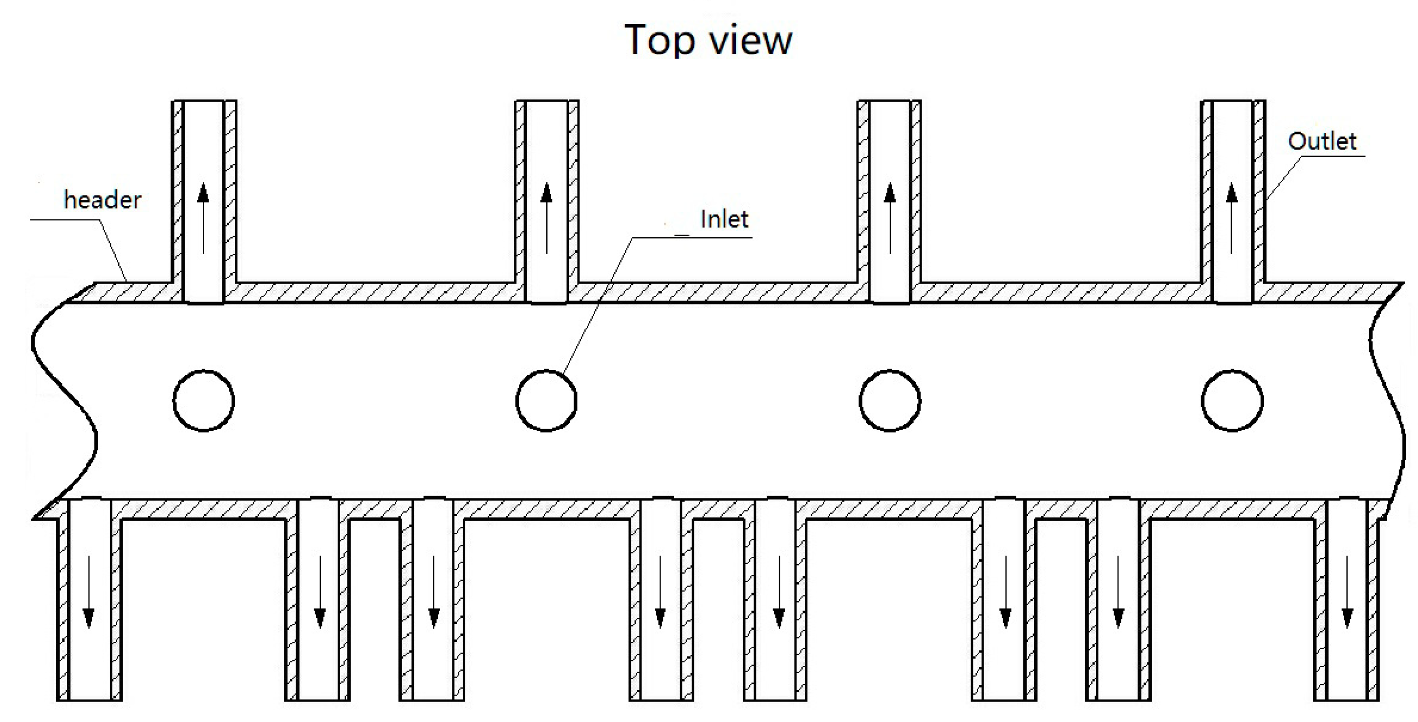
In order to analyze the two-phase flow distribution inside intermediate header, the header is modeled in Figure 9. The two-phase flow distribution experimental facility is applied to simulate the inlet and geometrical structure of this header. Two torrent inlets are adopted to test the two-phase flow distribution at this header. The inlet gas and liquid phase superficial velocities are applied at this header. The gas velocity is less than the normal velocity 15–20 m/s and the experimental gas velocities are setup among 2 to 9 m/s to simulate the actual gas velocities at intermediate header.
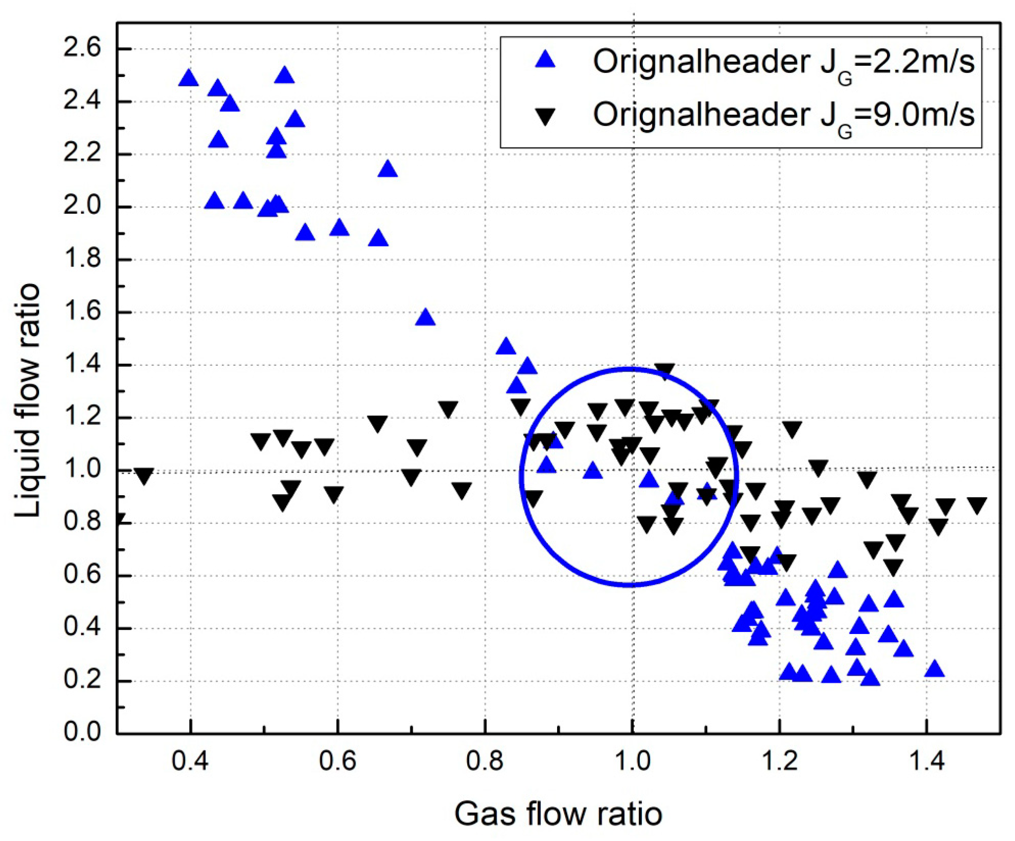
The experimental study of the two-phase flow distribution is shown in black and blue points in Figure 10 and the flow distribution are far from uniform, which the gas and liquid flow ratio is 1. The parallel tubes are far from −20% to +20%. The 9 m/s gas inlet deviation is reached at about −40% to +40%. The gas velocity at minimum value will increase the thermal deviation at certain parallel tubes and the tube may be overheated. At the same time, the gas velocity at maximum value may keep only the saturated temperature. The experiment answers the question of why there is very high thermal deviation at parallel tubes of water-cooled walls.
Based the operation data at vertical water wall tubes, ANSYS is applied to simulate the thermal stress during flexible operation. ANASYS results of the numerical simulation do confirm the existence of huge deformation in parallel tubes, which requires special attention in the future.

4. Thermal Stress and Cyclic Stress Analyses

4.1. Geometrical Model

For the 600 MW coal-fired power generation unit, the 2-m high front vertical water-cooled wall is chosen as the simulation element. In contrast to previous studies on parallel tubes, this paper mainly focuses on the thermal stress distribution at the front vertical water wall during long-term operation at a peaking power plant under the minimum operating load. According to the operating data, when the boiler operates under minimum load, the local tube temperature difference in the front vertical tube panel can reach up to 160 °C.
To reveal the thermal and cyclic stresses, the front wall is reduced to a two-dimensional planar model of 20.355 m × 2 m, as shown in Figure 11a. In this simulation, the width of the front wall is 20.355 m and the height of the front wall is 2 m instead of the actual height because of the variations in tube temperature along the height of the front wall. The tube temperature is processed as a function along the width and as a constant along the height, as shown in Figure 11b. The finite element software ANSYS is used to analyze the thermal stress of the simplified model of the front wall. The two-dimensional plane55 element is used in the thermal stress analysis. When the structure is analyzed, it is converted into a two-dimensional plane182 element and mapped by a structural mesh in Figure 11a. Figure 11b shows the tube temperature distributions.

4.2. Planar Stress Equation

The mathematical model can be processed as a planar stress problem, allowing the planar stress equation to be constructed as follows:
According to the differential equation, the thermal stress along the front water-cooled wall can be solved based on the material properties and boundary conditions using the finite element software ANSYS. Because the thickness at the water-cooled walls is of a significantly smaller scale than the height and width, a 2-D approach is applied to simulate the stress distribution in this area instead of a 3-D analysis.

4.3. Material Properties

The water-cooled wall material is 15CrMoG, whose material yield strength, allowable stress, elastic modulus, and other physical properties are provided in Table 3 [20]. The yield strength data of the 15CrMoG (Table 3) has been obtained from the elastic modulus and thermal expansion data in the temperature range from 20 °C to 600 °C.

4.4. Boundary Condition

The operating data of the power plant provide the tube temperature distributions along the parallel vertical tubes. This paper mainly studies the thermal stress caused by the temperature differences among the adjacent vertical water-cooled tubes and does not consider the influence of the mechanical stress caused by the inner pressure. When the tube temperature distribution condition is applied, the temperature data are introduced to the two-dimensional planar model according to the operating data. The centerline of the front wall is a man-made zero displacement of the utility boiler. A displacement constraint in the X direction is imposed on the centerline of the water-cooled wall in the finite element model. A displacement constraint in the Y direction is applied at the top line such that the front wall can expand freely downward along the Y direction. The tube temperature is distributed along the length of the planar model linearly. The instant temperature boundary condition is shown in Figure 11 based on the real time measuring data from the DCS.

4.5. Thermal Stress and Cyclic Stress Results and Analysis

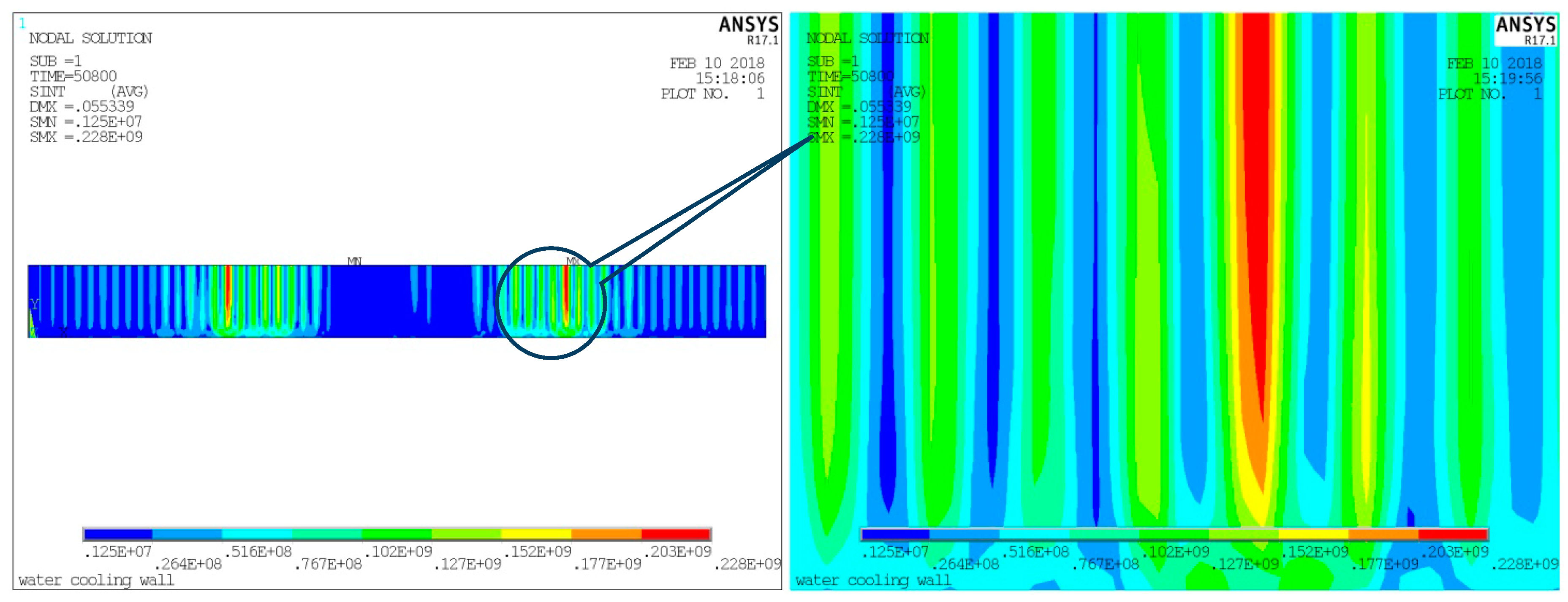
Figure 12 shows the instantaneous thermal stress distribution contour at the front wall when the measured tube temperature differences reach the maximum of 160 °C. The maximum thermal stress appears between the 44th and 45th tube temperature-measuring thermocouples at the front wall. The adjacent measuring temperature difference is presumed to be distributed linearly along the seven parallel tubes from 344 °C to 504 °C. According to the yield strength and allowable stress of the 15CrMoG material shown in Table 3, the maximum stress is 228 MPa, which is higher than the yield strength of the material at 500 °C and considerably higher than the allowable stress at the same temperature; thus, permanent plastic deformation may occur locally. Regarding 15CrMoG, the shear stress from the thermal stress becomes larger in areas with higher tube temperatures, and local permanent deformation will occur according to the third strength theory. Local displacement may occur in this area; such displacement is not safe according to the mechanical design and engineering design standards.
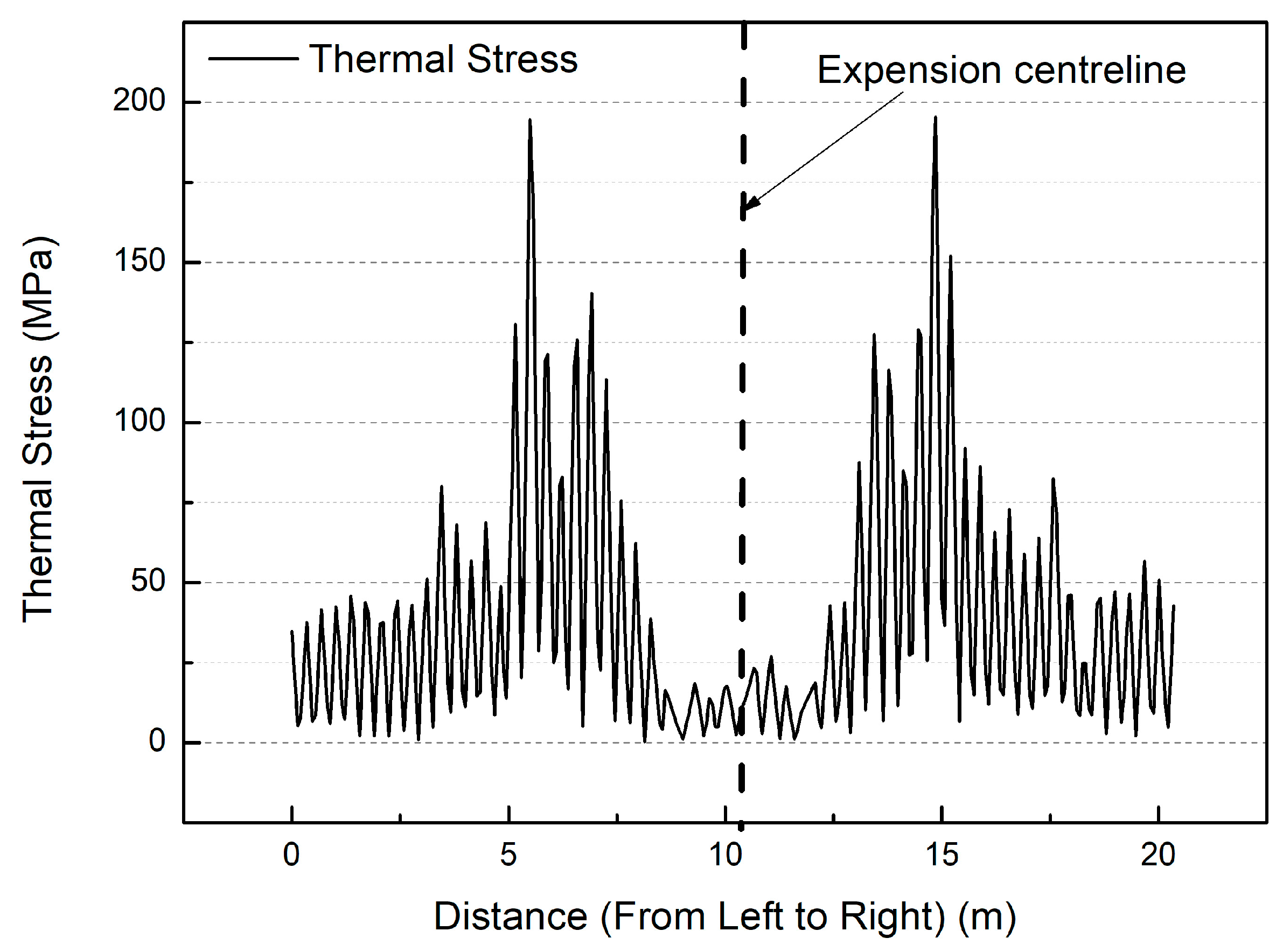
Figure 13 shows the thermal stress distribution at the top of the front wall along the width under the maximum thermal stress. As shown in Figure 13, the thermal stress distribution exhibits a bimodal shape, and the thermal stress increases sharply at a distance of approximately 5 m from the middle of the front wall, reaching a maximum value of 228 MPa. This maximum thermal stress is greater than the yield strength of the material.
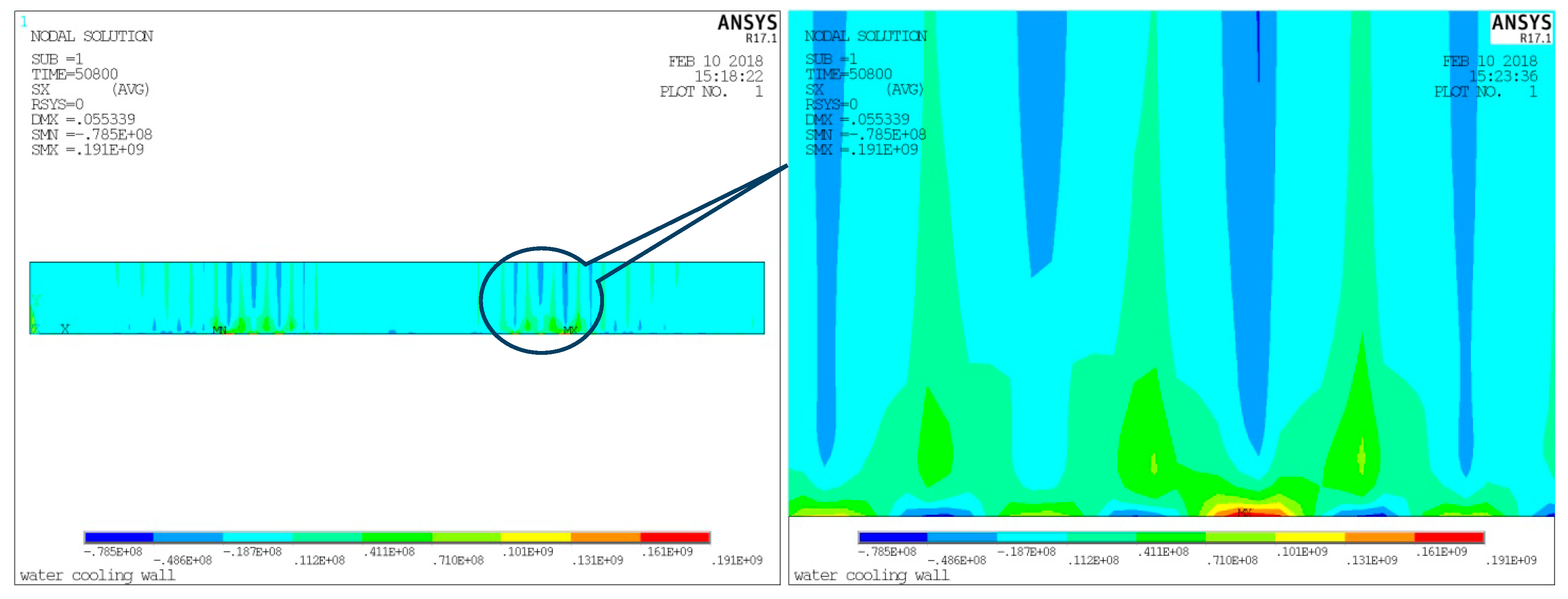
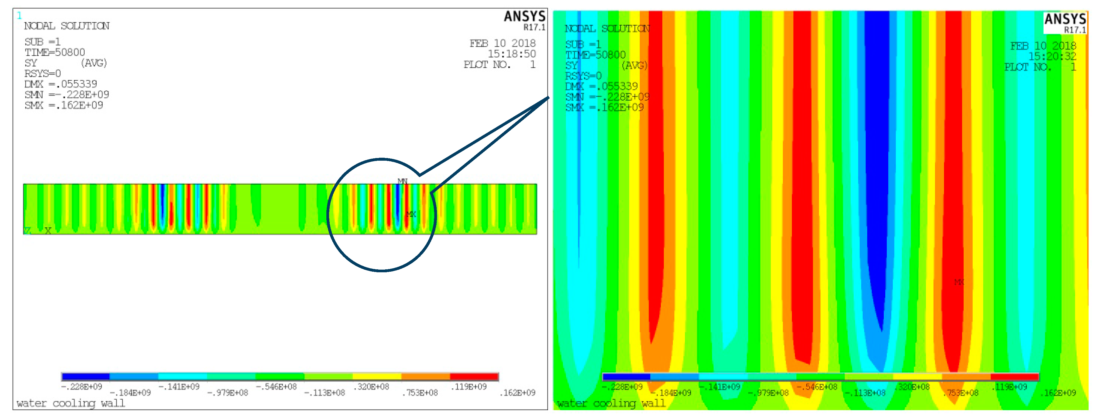
Figure 14 shows the thermal stress distribution in the X-direction of the front wall under the maximum tube temperature difference. The maximum value appears at the bottom of the mesh area. The maximum value is 191 MPa, which is tensile stress and is greater than the allowable local stress strength. As shown in the top of Figure 14, the blue area suffers from a compressive stress of 78.5 MPa. In selected areas, the top vertical water walls suffer from compressive stress and the bottom vertical water walls undergo tensile stress in the X direction; Figure 15 shows the thermal stress distribution in the Y direction of the front wall under the maximum tube temperature difference. A larger tube temperature difference will cause higher thermal stress in this area. The maximum compressive stress is 228 MPa in the area with the highest tube temperature. The maximum tensile stress is 119 MPa. The shear stress of this area exceeds the allowable stress and yield strength of the material. Residual stress may occur in this area because of the local deformation.
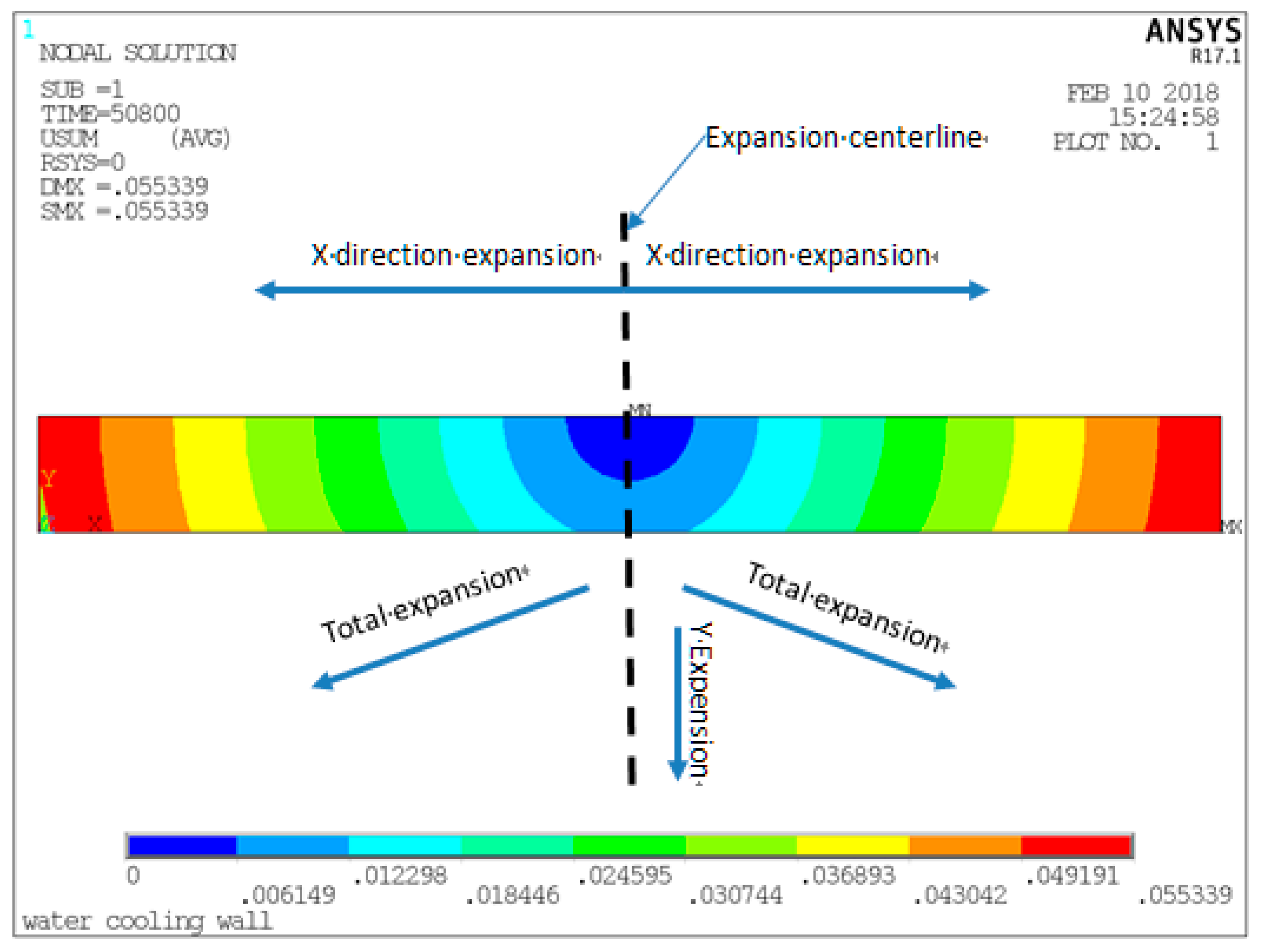
To verify the simulation, the vertical water wall expansion at the front wall is shown in Figure 16. This figure illustrates the expansion at the sidewall under the complex tube temperature distribution. The front wall expands downward according to the design of utility boiler. The boundary condition is proven to follow the actual condition.
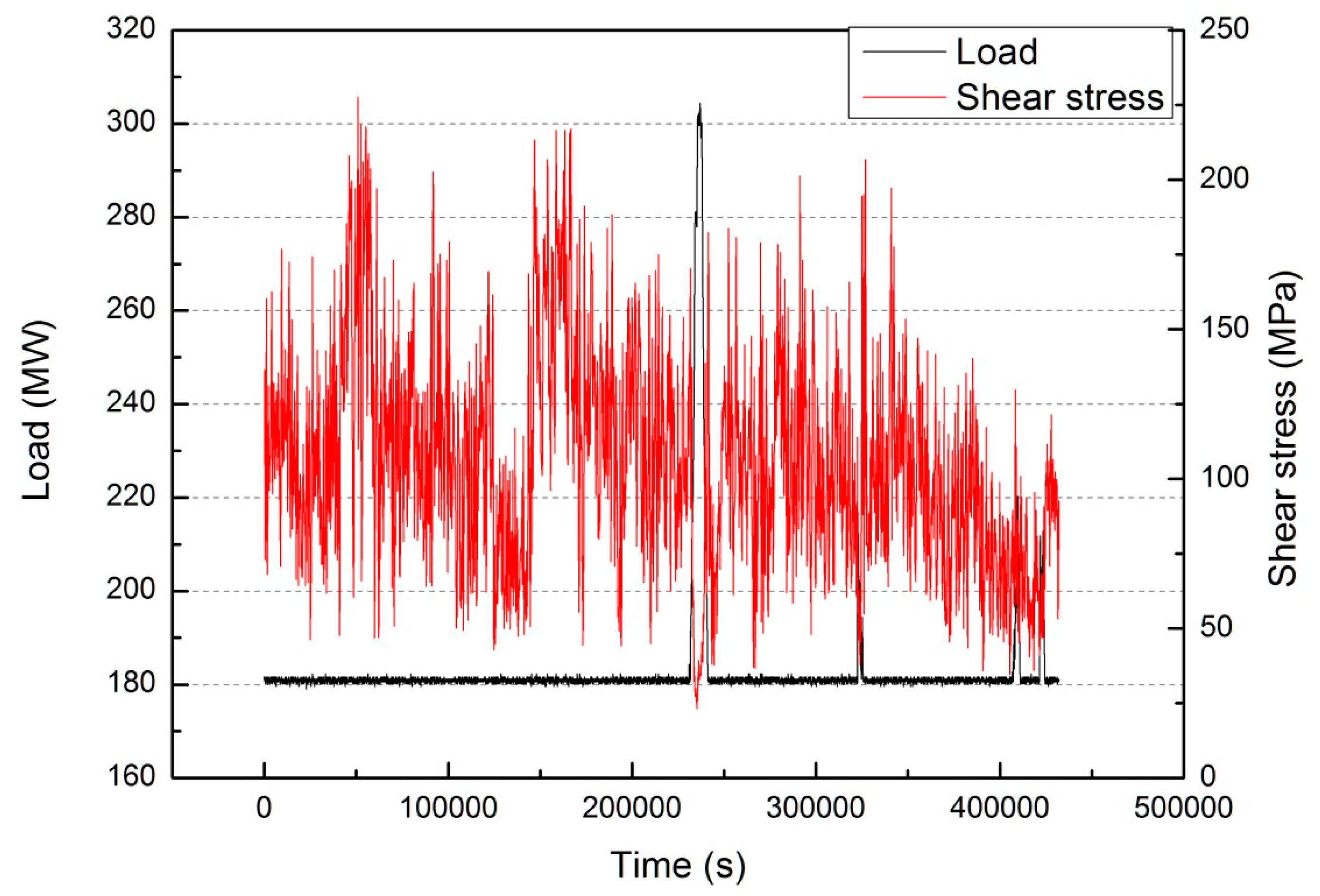
As shown in Figure 17, when the boiler operates at a load of 180 MW, the maximum shear stress appears and reaches 228 MPa according to the third strength theory. The shear stress array for this point is simulated in Figure 17, where the power output changes over time. The shear stress impacts the cyclic stress of the front wall considerably. The thermal stress and cyclic stress of the most dangerous point at the front wall could be estimated, and the influence of the flexible operation on the lifetime consumption of the water-cooled wall can be further evaluated.

4.6. Cyclic Stress Analyses

The fatigue lifetime consumption from the S-N fatigue curves for the water-cooled wall is estimated using the thermal stress values obtained during the cycling simulation. The estimation is performed by applying the material fatigue curve according to ASME Boiler and Pressure Vessel Code Section VIII Pressure Vessel–Division 2–Alternative Rules.
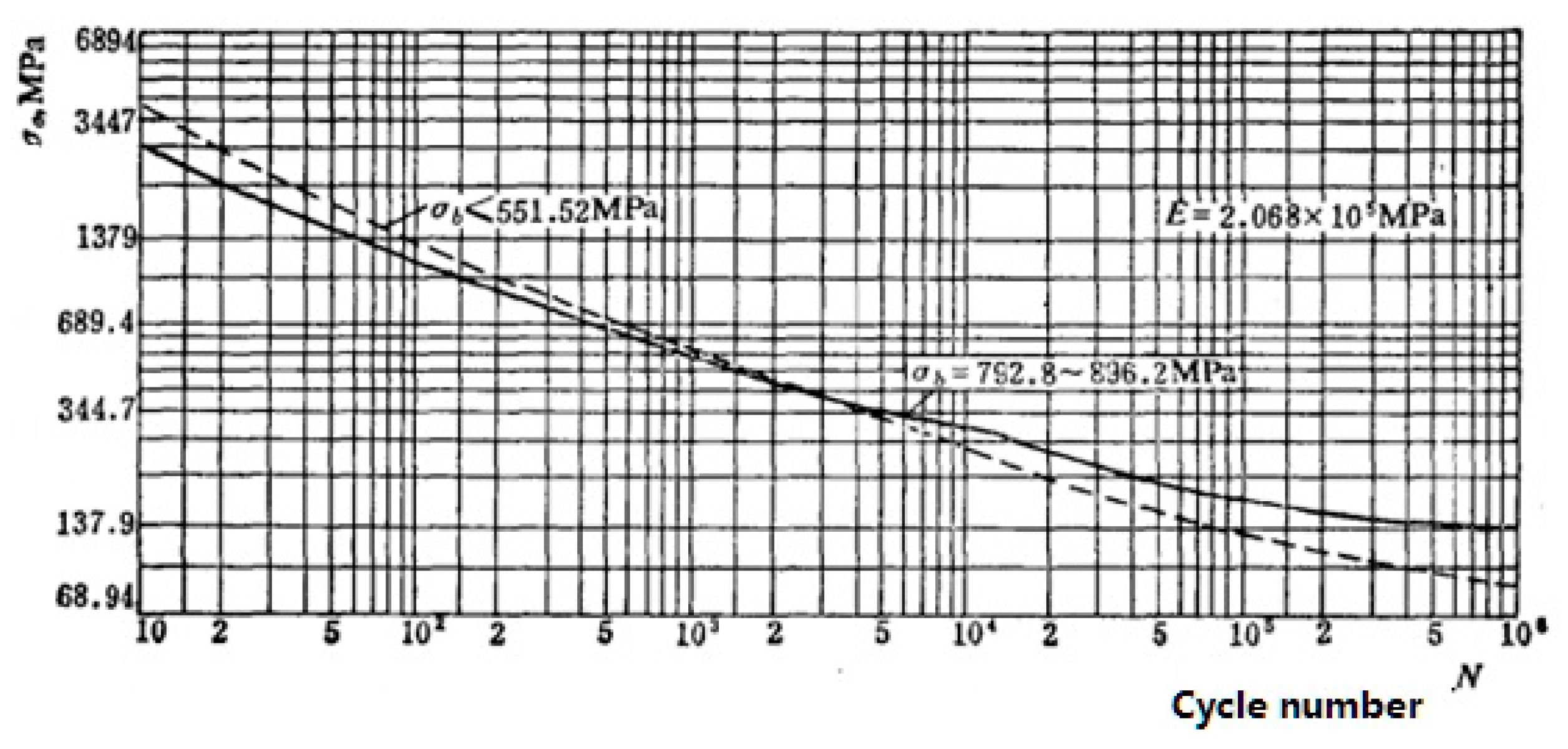
On the basis of the boiler pressure parts and lifetime evaluation method, the fatigue lifetime at the front wall is estimated [21,22]. After the maximum cyclic stress amplitude occurs, the desired cycle number N is calculated according to Figure 18; N is then multiplied by the ratio of the elastic modulus given in the design fatigue curve to obtain the elastic modulus E of the analyzed material as follows:
σ a = σ a i j E d E
where σa—actual cyclic stress amplitude; σaij—cyclic stress amplitude; Ed-elastic modulus given by the design fatigue curve, Ed = 2.068 × 10⁵ MPa; E—elastic modulus of the object material, in MPa. When the temperature is 350 °C, the elastic modulus of 15CrMoG is E = 1.76 × 10⁵ MPa. When the temperature is 500 °C, the elastic modulus is E = 1.63 × 10⁵ MPa. In fact, the fatigue curve from ASME Boiler and Pressure Vessel Code Section VIII Pressure Vessel–Division 2–Alternative Rules is suitable for temperatures below 370 °C.
As shown in Figure 17, the maximum stress amplitude is 75.1 MPa; thus,
σ a = 75.1 × 2.068 × 10 5 1.76 × 10 5 = 88.24   MPa < 91.93   MPa   ( Fatigue   limit )
The cyclic thermal stress will consume the additional lifetime of the water-cooled wall and cannot be ignored. The fatigue lifetime consumption at different thermal states is listed in Table 4.
The cyclic stresses at different operation states and flexible operation are compared in Table 4. The fatigue limit does not exceed 91.93 MPa for the cold, warm, hot, ultra-hot, load following, and flexible operation operating states. The cyclic amplitude under flexible operation is far higher than those under the other operation states. To ensure the safety of the vertical water wall, the cyclic lifetime consumption at the minimum load under the flexible power generation mode must be given particular attention. The thermal cyclic stress may exceed the stress at the cold state operation. The minimum load should be further limited in the flexible operation mode. The limitation may be related to the furnace combustion uniformity and the two-phase flow distribution inside the intermediate header before the vertical water wall. As a result, further investigations are required.

5. Conclusions

(1) When the boiler is operated at the minimum load of 180 MW for a long time in the flexible power generation mode, tube temperature difference fluctuations may occur among the parallel tubes. The maximum tube temperature difference among seven parallel tubes reaches 160 °C. The tube temperatures fluctuate mainly in the front wall and the left wall, whereas the tube temperature difference at the back and right walls remain relatively stable. The tube temperature difference decreases with increases in the boiler load. The most dangerous tube temperature differences occur when the boiler is operating under a load of 180 MW to 350 MW.
(2) When the boiler operates under the lowest load, the thermal stress reaches up to 227 MPa, which is greater than the yield strength of the material and may locally produce permanent plastic deformation. A greater local tube temperature difference results in a higher thermal stress. The safety of the water wall is strongly related to the tube temperature difference control. A more detailed tube temperature monitoring system may be required.
(3) When the boiler operates under the lowest load, the maximum stress amplitude reaches up to 103.03 MPa. Through the fatigue cycle calculation, the maximum stress amplitude caused by flexible operation under a load of 180 MW is larger than the fatigue limit of the material, causing the fatigue lifetime to be less than 106 and additional fatigue damage to occur. In the future, more attention must be paid to the water wall tube temperature during flexible operation.

Author Contributions

L.P. conceived the structural calculation models of water wall; L.P. and S.Y. calculated and analyzed experimental and structural data together; W.L. provided the analysis on the research. L.P., S.Y., L.D., and Y.Y. wrote the manuscript; L.P., S.Y., and L.D. revised the manuscript. All authors agreed on the final version of the manuscript.

Funding

This research has been supported by a project of the National Key R&D Program of China (No. 2017YFB0602101).

Acknowledgment

The authors are grateful for the financial support from Department of Science and Technology, China. The authors also greatly appreciate the data collection help from Feng Wang, GD Power Development Co. Ltd.

Conflicts of Interest

The authors declare no conflict of interest.

Nomenclature

Abbreviation
DCSDistributed Control System
ZGMZ medium speed; G- Great; M-Mill
EPRIElectric Power Research Institute
BMCRBoiler Maximum Continuous Rate
ASMEAmerican Society of Mechanical Engineers
HRSGHeat Recovery Steam Generator
NOxNitric Oxide metabolite
Symbols
σstress
τstrain
xX direction in the rectangular coordinate system
yY direction in the rectangular coordinate system
εgas steam combined cycle
γshearing strain
αthermal expansion coefficient
μPoisson ratio
Eelastic modulus
Tmaterial temperature
Gbody force
βgas or liquid flow ratio
wgas or liquid mass flow rate
Nthe total amount of parallel tube numbers
kGas or liquid phase, g-means gas phase, l means liquid phase
Subscripts
aactual cyclic amplitude
aijcyclic amplitude
ddesign
itube temperature thermocouple number
jparallel tube number
XCartesian coordinate X direction
YCartesian coordinate Y direction

References

  1. Stappel, M.; Gerlach, A.K.; Scholz, A.; Pape, C. The European Power System in 2030: Flexibility Challenges and Integration Benefit; Agora Energiewende: Berlin, Germany, 2017. [Google Scholar]
  2. EPRI. Electric Power System Flexibility Challenges and Opportunities; Electric Power Research Institute: Palo Alto, CA, USA, 2016. [Google Scholar]
  3. Jones, D.; Sakhel, A.; Buck, M.; Graichen, P. The European Power Sector in 2017: State of Affairs and Review of Current Developments; Agora Energiewende and Sandbag: Berlin, Germany, 2018. [Google Scholar]
  4. Henderson, C. Increasing the Flexibility of Coal-Fired Power Plants; IEA Clean Coal Centre: London, UK, 2014. [Google Scholar]
  5. Modliński, N.; Szczepanek, K.; Nabagło, D.; Madejski, P.; Modliński, Z. Mathematical procedure for predicting tube metal temperature in the second stage reheater of the operating flexibly steam boiler. App. Therm. Eng. 2019, 146, 854–865. [Google Scholar] [CrossRef]
  6. Viswanathan, R. An Overview of Failure Mechanisms in High Temperature Componentd in Power Plants. Available online: https://www.gruppofrattura.it/ocs/index.php/ICF/ICF10/paper/download/4443/6452 (accessed on 21 March 2019).
  7. Farragher, T.P.; Scully, S.; O’Dowd, N.P.; Leen, S.B. Development of life assessment procedures for power plant headers operated under flexible loading scenarios. Int. J. Fatigue 2013, 49, 50–61. [Google Scholar] [CrossRef] [Green Version]
  8. Taler, J.; Węglowski, B.; Taler, D.; Sobota, T.; Dzierwa, P.; Trojan, M.; Madejski, P.; Pilarczyk, M. Determination of start-up curves for a boiler with natural circulation based on the analysis of stress distribution in critical pressure components. Energy 2015, 92, 153–159. [Google Scholar] [CrossRef]
  9. Pearson, J.M.; Anderson, R.W. Root Causes of Transient Tube Temperature Anomalies Measured in Horizontal Gas Path HRSGS. Available online: http://competitivepower.us/pub/pdfs/ROOT-CAUSES-OF-TRANSIENT-TUBE-TEMPERATURE-EPRI-2001.pdf (accessed on 21 March 2019).
  10. Cochran, J.; Lew, D.; Kumar, N. Making Coal Flexible: Getting From Baseload to Peaking Plant. Available online: https://www.21stcenturypower.org/assets/pdfs/cornerstone-flexible-coal.pdf (accessed on 21 March 2019).
  11. Cochran, J.; Miller, M.; Zinaman, O.; Milligan, M.; Arent, D.; Palmintier, B.; O’Malley, M.; Mueller, S.; Lannoye, E.; Tuohy, A.; et al. Flexibility in 21st Century Power Systems. Available online: https://www.osti.gov/biblio/1130630 (accessed on 21 March 2019).
  12. Ma, J. A review of flexible operation and high efficency technology with wide load in thermal power units. Therm. Turbine 2017, 46, 108–116. [Google Scholar]
  13. Mu, C.; Ju, W.; Huang, J.; Zhang, J. Review and prospect of technologies of enhancing the flexibility of thermal power units. Therm. Power Gener. 2018, 47, 1–7. [Google Scholar]
  14. Pescia, D. Flexibility in Thermal Power Plants-With a Focus on Existing Coal-Fired Power Plants; Agora Energiewende: Berlin, Germany, 2017. [Google Scholar]
  15. Otegui, J.L. Failure Analysis—Fundamentals and Applications in Mechanical Components; Springer Science & Business Media: New York, NY, USA, 2013. [Google Scholar]
  16. Coleman, K.; Hack, H. Potential impacts of flexible operations on subcritical conventional coal-fired boilers. Environ. Eng. 2009, 135, 449–458. [Google Scholar]
  17. Rosinski, S.T.; Coleman, K.; Berasi, M.; Carney, C.; Woerz, U.; Sanchez, A.; Sigali, S.; Rossi, N. Online creep-fatigue monitoring of cyclic operation in a coal-fired power plant. In Proceedings of the ASME 2017 Pressure Vessels and Piping Conference, Waikoloa, HI, USA, 16–20 July 2017. [Google Scholar]
  18. Taler, J.; Dzierwa, P.; Taler, D.; Jaremkiewicz, M.; Trojan, M. Monitoring of Thermal Stresses and Heating Optimization Including Industrial Applications; Nova Science Publishers: New York, NY, USA, 2016. [Google Scholar]
  19. Taler, J.; Węglowski, B.; Sobota, T.; Taler, D.; Trojan, M.; Dzierwa, P.; Jaremkiewicz, M.; Pilarczyk, M. Thermal performance and stress monitoring of power boiler. In Proceedings of the ASME 2016 Power Conference, Charlotte, NC, USA, 26–30 June 2016. [Google Scholar]
  20. Li, B.; Wang, H.; Liang, X.; Wang, C.; Shi, B. The Study on temperature distribution of water-cooled wall in Ultra-supercritical utility boiler based on finite element numercial simulation. Util. Boil. Tech. 2016, 47, 67–71. [Google Scholar]
  21. Noda, N.; Hetnarski, R.B.; Tanigawa, Y. Thermal Stress, 2nd ed.; CRC Press: Boca Raton, FL, USA, 2002. [Google Scholar]
  22. Parker, J.; Shingledecker, J. EPRI Initiatives related to Flexible Operation of High Temperature Power Plant. Available online: https://www.gruppofrattura.it/ocs/index.php/ICF/icf13/paper/download/11312/10691 (accessed on 21 March 2019).
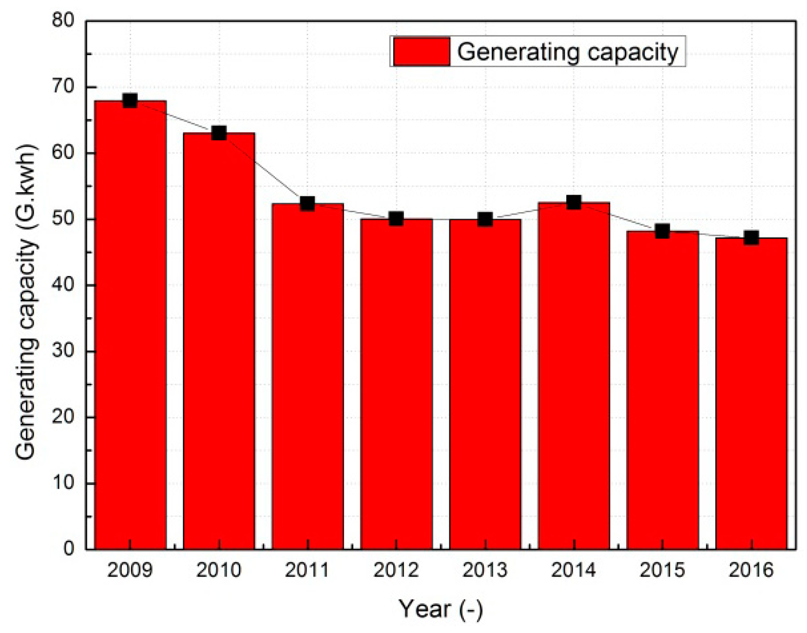
Figure 1. Generating capacity in a peaking power plant by year.
Energies 12 01170 g001
Figure 2. Operating hours by load bandwidth.
Energies 12 01170 g002
Figure 3. Spiral and vertical water-cooled wall inside the furnace.
Energies 12 01170 g003
Figure 4. Tube temperature distribution along the vertical water-cooled wall under the minimum load.
Energies 12 01170 g004
Figure 5. Tube temperature distributions at the front, left, back, and right vertical water walls.
Energies 12 01170 g005
Figure 6. Tube temperature differences at the front, left, back, and right wall.
Energies 12 01170 g006
Figure 7. Load and tube temperature difference vs. time at the highest tube temperature difference point.
Energies 12 01170 g007
Figure 8. Heat flux distribution comparison between high load and flexible operation at the four sidewalls.
Energies 12 01170 g008
Figure 9. Top view of original intermediate header.
Energies 12 01170 g009
Figure 10. The two-phase flow ratio distribution in original intermediate header.
Energies 12 01170 g010
Figure 11. Front wall model and temperature boundary of the finite element.
Energies 12 01170 g011
Figure 12. Shear stress contours along the front wall.
Energies 12 01170 g012
Figure 13. Thermal stress distributions along the width of the front wall at the highest tube temperature difference.
Energies 12 01170 g013
Figure 14. Thermal stress contour of the X direction at the highest tube temperature difference.
Energies 12 01170 g014
Figure 15. Thermal stress contour of the Y direction under the highest tube temperature difference.
Energies 12 01170 g015
Figure 16. Vertical water wall expansions at the front wall.
Energies 12 01170 g016
Figure 17. Shear stress cycle and load vs. time at the highest tube temperature difference point.
Energies 12 01170 g017
Figure 18. ASME fatigue design curve.
Energies 12 01170 g018
Table 1. Parameters of the 600 MW once-through supercritical coal-fired power plant.
ParameterValueUnit
Power output600MW
Main steam flow rate1950t/h
Main steam temperature571°C
Main steam pressure25.4MPa
Reheated steam flow rate1653.4t/h
Reheated steam temperature569°C
Reheated steam pressure4.56MPa
Economizer inlet water temperature290°C
Table 2. The geometrical structure and parameters of the vertical water-cooled wall.
ParametersValue and Unit
Water-cooled wall tube diameter, thickness, and pinches31.8 × 5.5, 57.5 mm
Tube material15CrMoG
Front and back wall tube numbers385 × 2
Left and right wall tube numbers271 × 2
Front, back, left, and right wall tube temperature thermocouples at the vertical water-cooled wall175
Table 3. Physical properties of 15CrMoG steel.
Item/UnitValues
Temperature/°C20100200300400500600
Yield Strength /MPa295-269242216198-
Allowable Stress /MPa147--14312896-
Elastic Modulus /GPa206199190181172163-
Thermal expansion coefficient/10−6/°C-11.912.613.213.714.00-
Thermal Conductivity/W/(m·C)-40.640.138.736.834.832.8
Density/kg/m37800------
Specific heat capacity/J/(kg·K)--590607657712800
Poisson’s ratio/-0.2840.2950.30.3010.3040.308-
Table 4. Cyclic stress of the vertical water wall during cold, warm, hot, ultra-hot, load following, and flexible operation.
Operating StateRated Pressure (MPa)Low Pressure (MPa)Cyclic Amplitude (MPa)
Cold27.26055.981
Warm27.264.903345.912
Hot27.267.020541.564
Ultra-hot27.269.107937.277
Load following27.2610.1835.076
Flexible operation (180–350 MW)17.503715.085588.24