Abstract
Due to their inherent advantages such as low cost, robustness and wide speed range, switched reluctance machines (SRMs) have attracted great attention in electrical vehicles. However, the vibration and noise problems of SRMs limit their application in the automotive industry because of the negative impact on driver and passengers’ comfort. In this paper, a new control method is proposed to improve the vibratory and acoustic behavior of SRMs. Two additional control blocks —direct force control (DFC) and reference current adapter (RCA)—are introduced to the conventional control method (average torque control (ATC)) of SRM. DFC is adopted to control the radial force in the teeth of the stator, since the dynamic of the radial force has a large impact on the vibratory performance. RCA is proposed to handle the trade-off between the DFC and ATC. It produces an auto-tuning current reference to update the reference current automatically depending on the control requirement. The effectiveness of the proposed control strategy is verified by experimental results under both steady and transient condition. The results show that the proposed method improves the acoustic performance of the SRM and maintains the dynamic response of it, which proves the potential of the proposed control strategy.
1. Introduction
The great potential of electrical vehicles (EVs) has led to many studies on the topic. As the core component of EVs, the electric motor and drive is very important. The peculiar operating modes and working conditions of the vehicles poses specific requirements for electric motor and drive systems. The switched reluctance machine (SRM) has been a strong candidate due to its inherent advantages such as simple structure, good fault tolerance, applicability in harsh environments and low cost [1]. However, its double salient structure leads to high nonlinearity and serious vibration and acoustic noise problems, which prevent it from being used in the automobile field. It has been pointed out that the main source of the vibration and acoustic noise for SRM is the electromagnetic force between the stator and rotor poles [2,3]. Different approaches have therefore been proposed to reduce the vibration and noise from the aspects of both geometric-optimization design and control strategies.
As it concerns the optimization-based design, several solutions have been proposed to improve vibration, mainly focused on the radial force reduction [4,5,6], the motor natural frequency manipulation [7,8], and the stator damping effect improvement [9].
Among the control approaches, the current shaping control method is usually adopted to reduce the SRM vibration and noise in the early stage of the research, such as the turn-on and turn-off angle advanced shift method [10], the random control angle method [11]; the two-stage [12] or three-stage commutation method. Due to their piezoelectric properties, lead zirconate (PZT) actuators have become an alternative method for semi-active/active vibration reduction [13,14]. However, all these control solutions in [13,14] require additional components—PZTs. Since the main source of the vibration is the variation of the radial force, it inspires the propositions of control strategies aiming to reduce the vibration by controlling the radial force directly [15,16,17,18,19]. In [15], the authors propose a PWM-based predictive control method, in which the direct instantaneous force control (DIFC) is adopted trying to obtain a smooth total radial force. In [16], the authors propose a control method combining direct instantaneous torque control with direct instantaneous force control, which tries to solve the torque ripple increase caused by adopting DIFC alone in [15]. However, this method has the disadvantage of increasing total losses, which can be up to 48% compared to the traditional method. In [17,18,19], the authors propose a new current profile to minimize the variation of the total radial force under unsaturated and saturated conditions. Besides, authors investigate the effect of control parameters on torque ripple, efficiency and vibration reduction. Yet, this method has use limitation for the three-phase SRM. Moreover, most of these research focus on the steady-state performance of the proposed method. Considering the complex traffic conditions in urban region, a control method used to reduce vibration and noise under both stable and transient conditions without slowing down dynamic response is necessary.
2. Materials and Methods
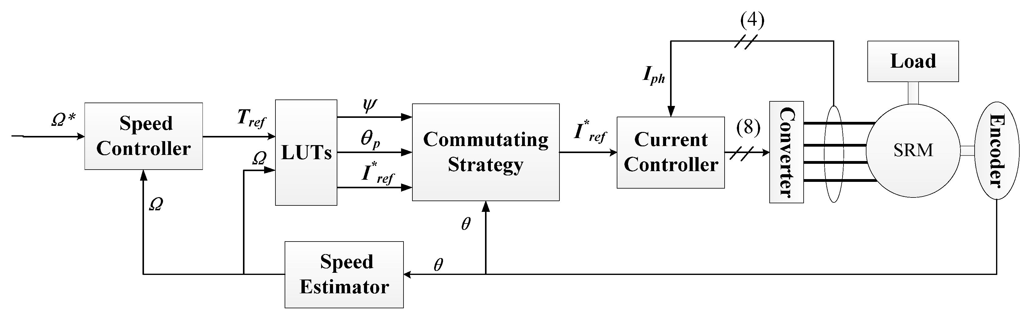
The proposed Direct Force Control (DFC) and Reference Current Adapter (RCA) vibration reduction control strategy for the SRM is presented in Figure 1. The average torque control, referred to in the figure as ATC, is a traditional control strategy that uses look-up tables (LUTs) to achieve different goals, such as torque ripple minimization, efficiency optimization at each operating point. The main idea of this control structure that will be detailed in the following parts is to combine the ATC with DFC, each controller being active depending on the characteristics of the machine related to the rotor position. Each part of the proposed control structure will be described in the following sections: ATC, DFC&RCA.
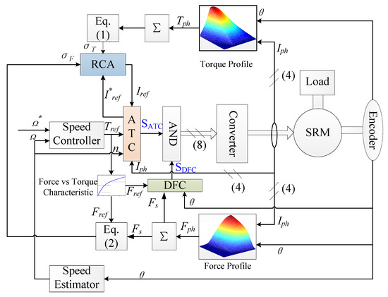
Figure 1.
Control structure of the proposed control method.
2.1. Conventional Control Strategy—ATC
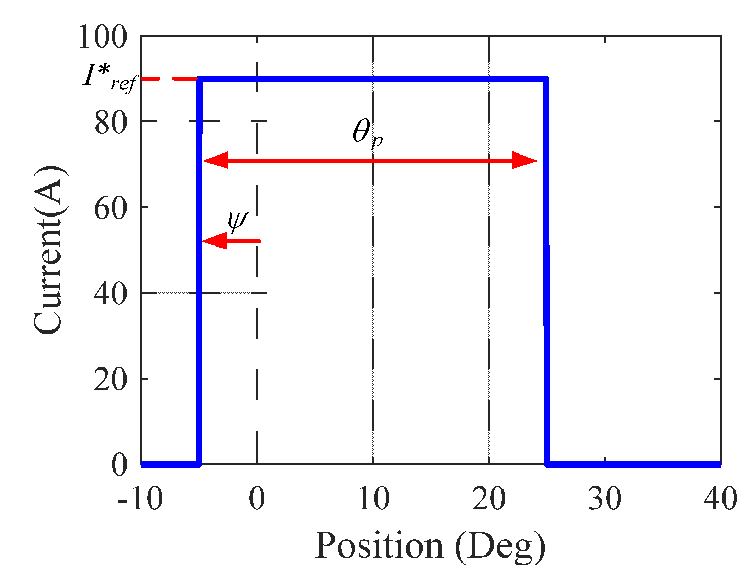
The proposed method in this paper is based on the traditional control method ATC, whose block diagram is shown in Figure 2. There are two controllers: the speed controller of the outer loop and the current controller of the inner loop. LUTs store the optimized control parameters. By using the reference torque and actual rotor speed as inputs, the control parameters I*ref, ψ and θp are then constantly updated, whose definitions are presented in Figure 3. Thus, the error between the reference current I*ref and the phase current I is used by the current control to compute a variable duty ratio such that the phase current emulates the reference value. It should be noted that Integral Proportional (IP) controller is adopted for the speed loop considering both overshoot and disturbances rejection [20] and Proportional Integral (PI) controller is introduced in the current loop to guarantee the dynamic response.
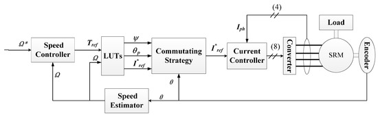
Figure 2.
Block diagram of ATC.
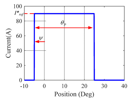
Figure 3.
Definition of control variables.
2.2. Vibraiton Reduction Block—DFC
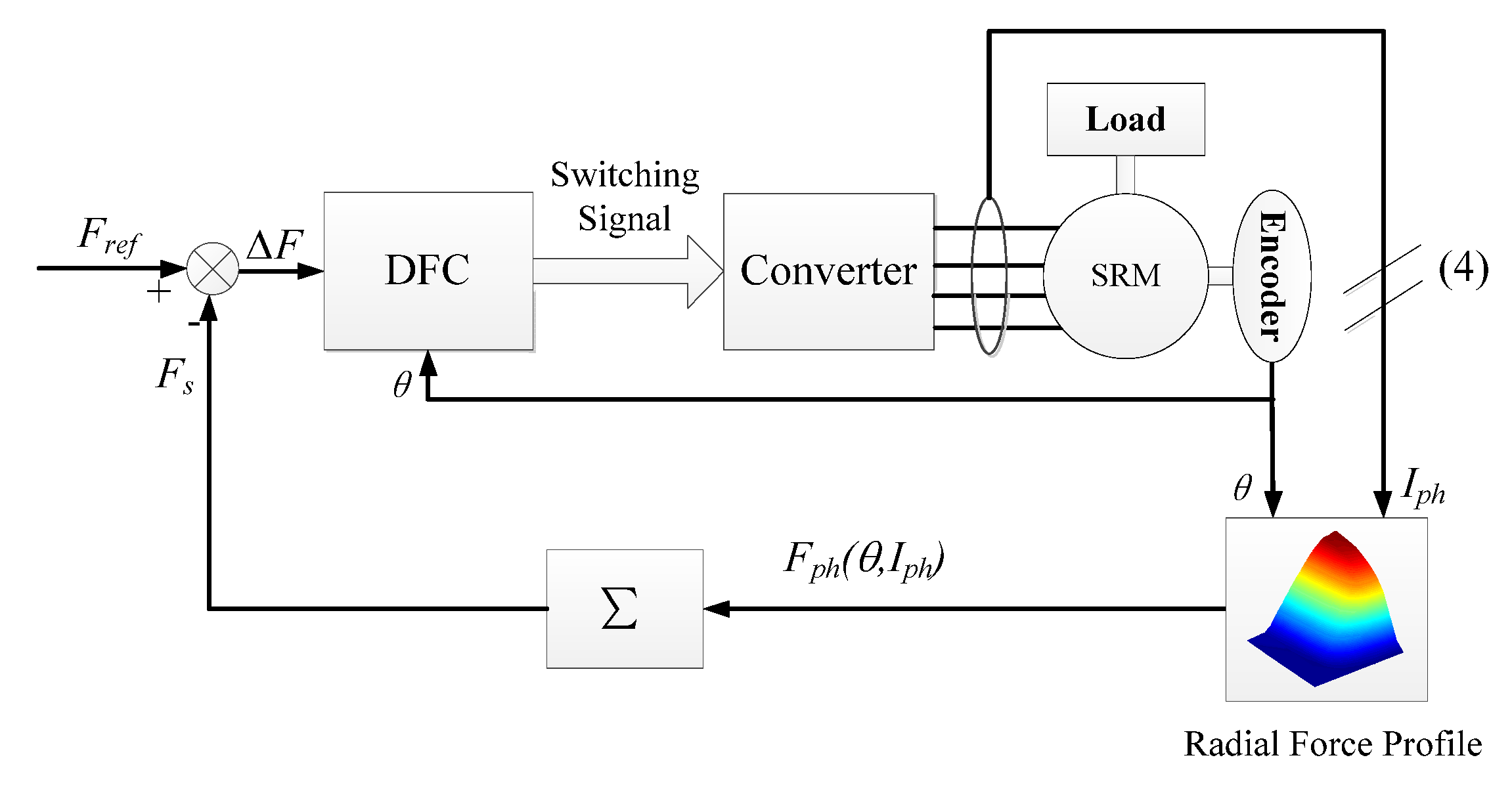
DFC is a control strategy inspired by direct instantaneous torque control (DITC) [21], whose aim is to obtain a smooth total torque by controlling the instantaneous phase torque. The objective of the adoption of DFC is to reduce the variation of the radial force so that to limit the mechanical excitation to reduce the vibration and noise of SRM. The control scheme of the SRM based on DFC is illustrated in Figure 4.

Figure 4.
Structure of direct force control drive system.
In Figure 4, the switching signals of the power converter are generated by the DFC block to reduce ΔF (Fref − Fs), defined as the difference between the desired total radial force Fref and the actual sum of the radial forces Fs. An asymmetric half-bridge converter is adopted, which can produce three different terminal voltages (positive, zero, negative) to the connected phase winding.
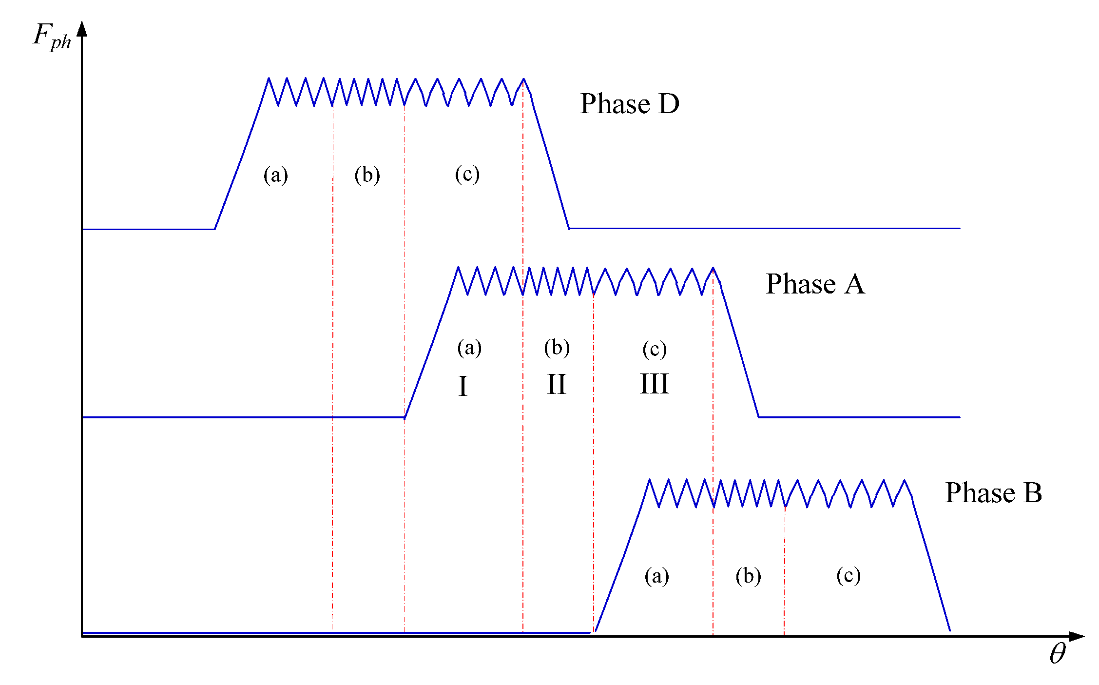
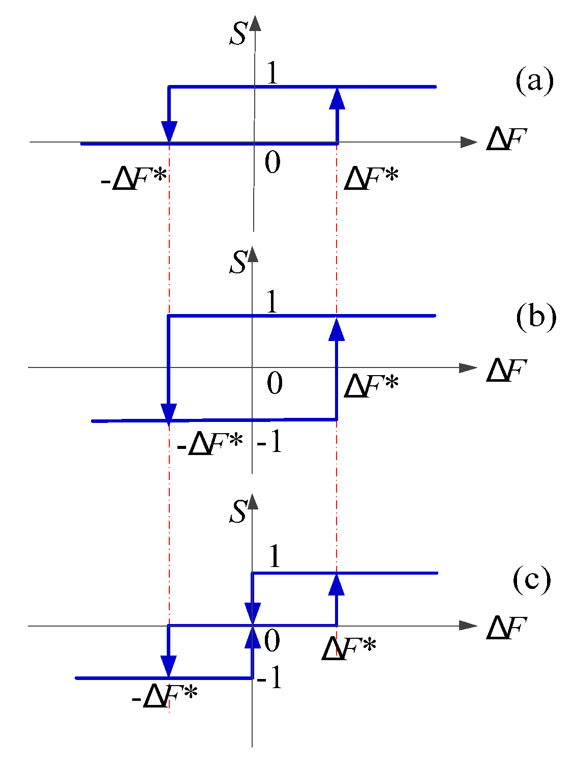
The introduced DFC block consists of three hysteresis controllers that produce the switching signals for each phase of the SRM. Depending on the position of the rotor, the whole controlling process can be divided into two conditions: the commutation mode and single excitation mode. In commutation mode, two adjacent phases are excited at the same time (periods I and III in Figure 5). In this case, the switching states S of the outgoing phase (phase D, period I or phase A, period III) and the incoming phase (phase A, period I or phase B, period III) follow the rules in Figure 6a,c, respectively. In single excitation mode, just one phase is excited (phase A, period II) following the rules in Figure 6b. The hysteresis bands are defined within the intervals [−ΔF*, ΔF*], where ΔF* is the hysteresis band chosen by the user.
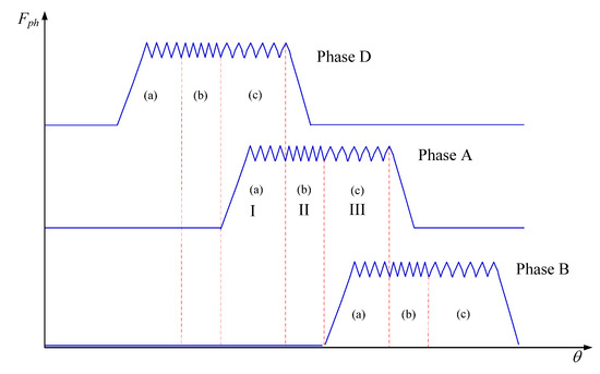
Figure 5.
DFC: region division and control modes.

Figure 6.
Diagram of the hysteresis controllers. hysteresis controllers (a); hysteresis controllers (b); hysteresis controllers (c).
As shown in Figure 5 and Figure 6, different hysteresis controllers are adopted in different regions, the hysteresis controllers used in this work are designed considering the output torque performance, the efficiency and the vibration of the machine. In part I, the force from phase A of the SRM is smaller than the one of phase D, and then hysteresis (a) allows a limited switching rate and a fast increase of the current in order to provide the requested output torque. In part II, a high dynamic is required, so that the actual total force can emulate the reference value, which can be obtained by hysteresis (b). In part III, the force of phase A is high (near aligned position) and hysteresis (c) has shown to allow a restricted variation of the force around Fref to limit the vibration during the commutation period.
It can be seen in Figure 4 that there is no current limitation for DFC. To obtain a smooth DFC, a peak current is required, which will lead to peak phase torque that causes a problem of torque ripple. In traction applications, torque ripple can potentially excite the downstream power train, which can lead to undesirable jerking of the vehicle or secondary noise radiating as gear whine from the transmission. Thus, torque ripple is also not desirable. Therefore, a reference current is induced to limit the peak torque in each phase.
2.3. Blocks Ajustment—RCA
In this paper, RCA block is proposed to balance torque ripple and vibration problem. The purpose of RCA is to manage the tradeoff between torque ripple minimization and vibration reduction by updating the current reference. The value of the current reference is constantly adapted based on the variations of the torque and radial force within an electrical period, noted σT and σF respectively. These criteria are calculated using the following expressions:
where, T(t), F(t) are the transient total torque and total radial force, respectively; Tavg, Fref are the mean value of the total torque and the total radial force reference during one electrical period, respectively; Tc is the cycle time of one electrical period.
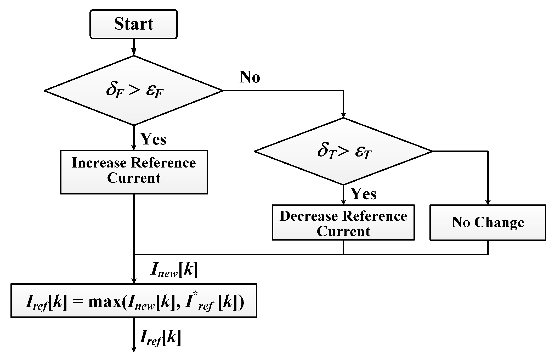
The basic idea of RCA is to increase or decrease the current reference to reduce the variation of the radial force or the variation of the torque. Based on the fact that DFC needs a higher current to obtain a smooth radial force to reduce vibration and noise, and ATC requires a relative smaller current to reduce torque ripple, the flowchart of RCA is illustrated in Figure 7. εF and εT are the upper limits for the variations of the total radial force and torque. The increment or decrement step of the current adapter ∆I is a constant value that can be tuned by the user: a too small value will slow down the current update, while a too big value will make the system unstable. In this paper, the RCA parameters values are εF = 0.5, εT = 0.12 and ΔI = 0.5. The chosen values for εF and εT offer an acceptable tradeoff between torque ripple minimization and vibration reduction. Iref [k] is the output of the reference current adapter at time instant k. Inew [k] is the intermediate current reference value at time instant k. I*ref [k] is the reference current obtained from the optimized look-up table in ATC.

Figure 7.
Flowchart of the proposed reference current adapter.
Firstly, σT and σF are calculated with Equations (1)–(2) and compared to constants εT and εF to determine the intermediate current reference Inew [k]. It follows the rules as: the torque criterion is considered only if the vibration criterion is satisfied, that is to say, the current reference will be reduced when σF ≤ εF, otherwise, it will be increased to reduce the variation of the radial force. If both variations of total torque and total radial force are within their allowed range (σF ≤ εF, σT ≤ εT), the reference current will not change and the intermediate current reference Inew [k] will be compared with the current reference signal Iref* [k] from the ATC to ensure the torque output of the machine. Finally, the output of the reference current adapter is equal to the maximum between I*ref [k] and Inew [k].
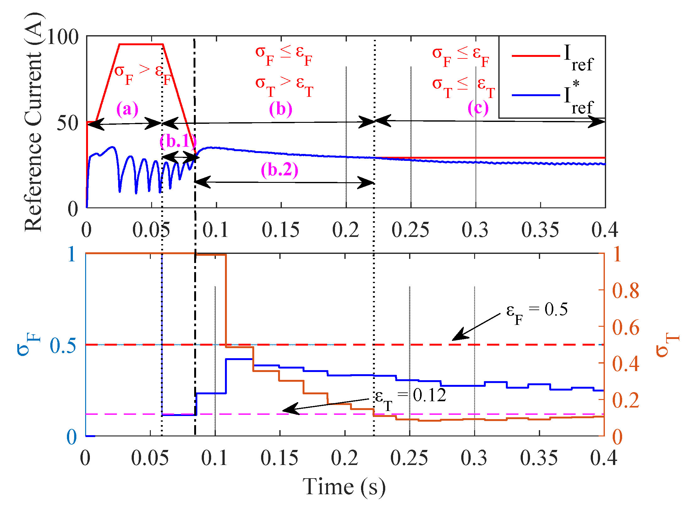
For instance, the adaption process handled by the reference adapter is shown in Figure 8. The reference current Iref increases at the beginning (region (a)) to reduce the force variation σF and to meet the requirement of εF. Within region (b), where σF ≤ εF and σT > εT, the adaption process is made up of two parts: region (b.1) and region (b.2). Inside the region (b.1), Iref starts to decrease in order to reduce the torque ripple as soon as σF ≤ εF. Inside the region (b.2), the Iref increases at first and is equal to reference current Iref*obtained from the optimized look-up table to guarantee the output torque to emulate the reference speed nref. Then, the reference current I*ref from the LUT starts to decrease slowly because the difference between the actual speed n and reference speed nref is reducing, which leads to the reduction of the reference torque Tref (output of the speed controller). As the actual speed n approaches the reference speed nref, the reference current I*ref decreases faster and becomes smaller than the Iref the reference current adapter stops updating and enters the region (c) where the current is constant and σF ≤ εF, σT ≤ εT.
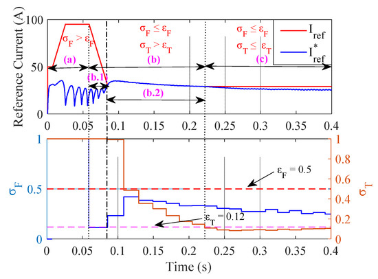
Figure 8.
Reference current adaption progress at Ω* = 600 r/min and TL = 3 N∙m.
It should be noted that, after introducing block RCA, the reference current Iref is not always equal to the I*ref from LUTs in ATC directly. It is the value, which can satisfy both the force and torque variation standard aforementioned. Comparing Figure 1 to Figure 2, it can be seen that, the reference current I*ref produced by LUTs in ATC is sent to RCA to generate a new reference current Iref, then, Iref is delivered to commutating strategy block in ATC for current regulation by comparing with the actual phase current.
3. Experimental Results
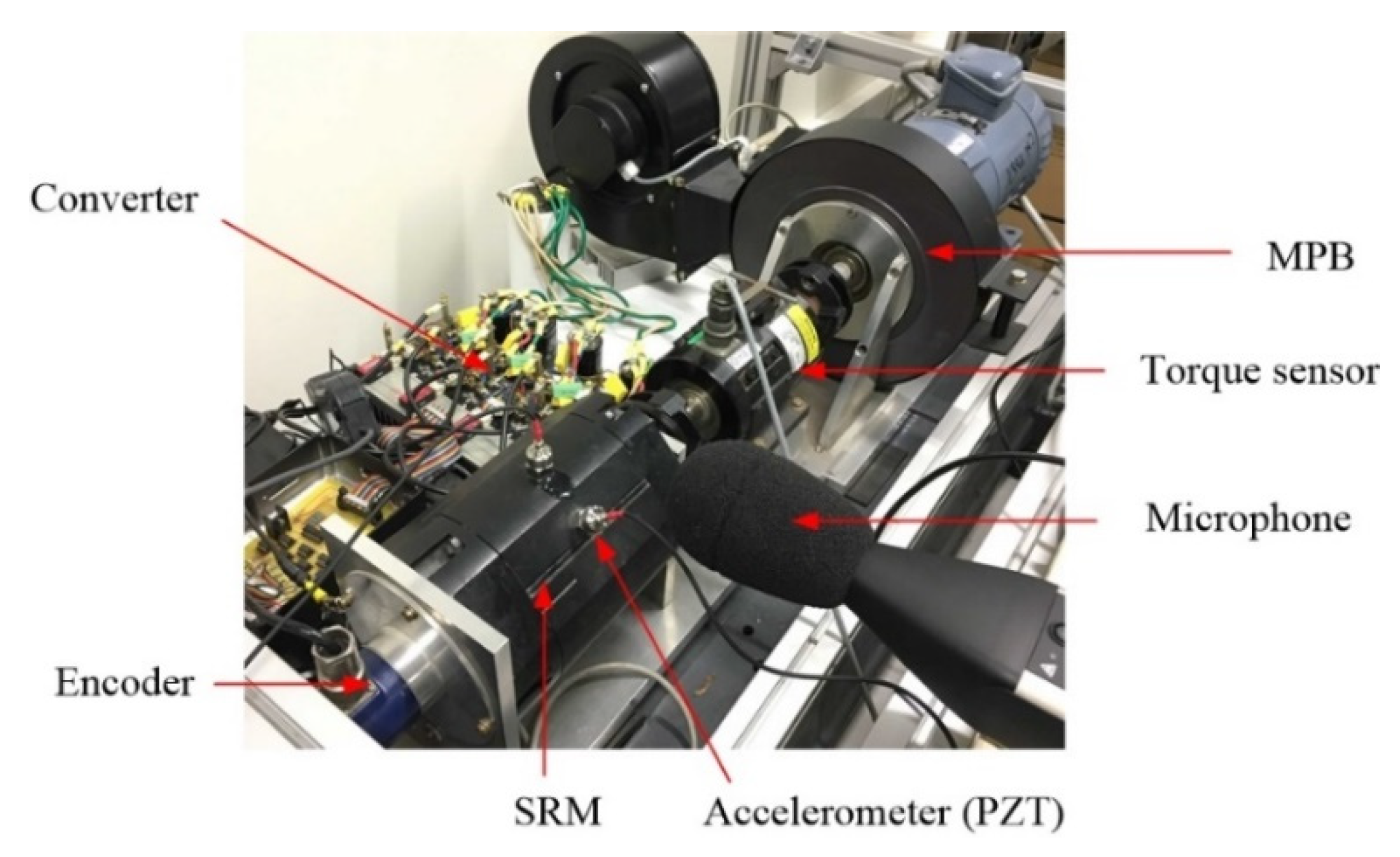
To validate the proposed control strategy, some experimental tests are evaluated by using an 8/6 SRM prototype (the machine parameters are given in Table 1). The test bench is presented in Figure 9. The experiments are performance by using a microprocessor combined with a FPGA. The FPGA board features the Xilinx Virtex-5 FPGA running at 100 MHz, with 6 ADC and 16 digital I/O channels. The microprocessor has a CPU frequency of 1 GHz and level-2 cache of 1 MB. The FPGA and microprocessor are connected by a Physical High Speed (PHS) bus. The phase currents are measured by four Hall-effect current sensors, whose obtained data are sent to A/D of FPGA. The rotor position is measured by an incremental encoder with a resolution of 0.1° mounted on the rotor shaft. The magnetic particle brake (MPB) provide a controllable load torque which can be regulated via PC. The acceleration data is acquired with an accelerometer (PZT) located over A-phase tooth, in the middle of the axial lamination (see Figure 9). The accelerometer is MMF KS76C IEPE (102.11 mV/g) with MMF M32 conditioner. The noise is measured with a microphone which is placed near the test bench at a distance close to 20 cm.

Table 1.
Electrical parameters of the investigated SRM.
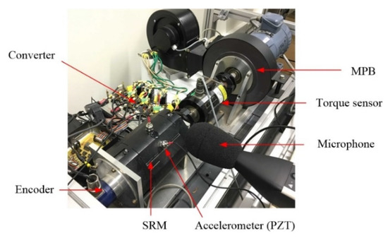
Figure 9.
Setup of the test bench.
3.1. Steady Condition
At first, the experimental results of ATC and DFC&RCA are compared under steady conditions, which means the actual speed is equal to the reference speed. The curves of current, torque and radial force are delivered to a four-channel oscilloscope for saving. In which, the torque and radial force are estimated in FPGA by interpolating the torque and force profiles presented in Figure 1.
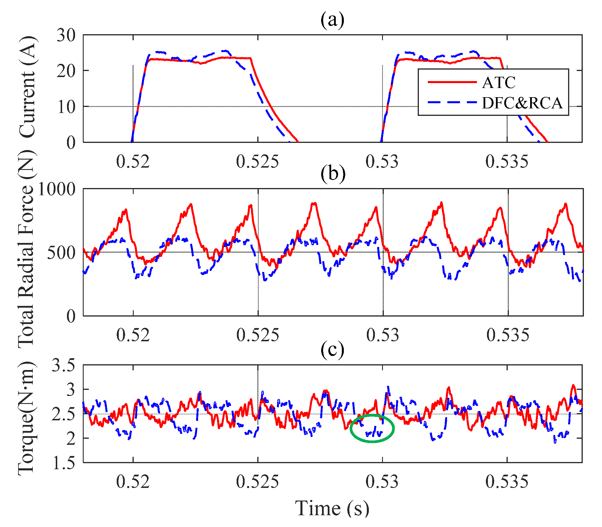
The experimental results of the closed-loop system, the phase current, the sum of radial forces and the electromagnetic torque are illustrated in Figure 10 for a reference speed Ω* of 1000 r/min and a load torque TL of 2 N∙m. The root mean square currents of DFC&RCA and ATC are similar, which are 16.7 A (ATC) and 16.9 A (DFC and RCA), so that their copper losses are quite identical. The torque ripple has been increased by 6% because of the concave part of the torque shown in Figure 10c (within green circle). This concave part is caused by DFC, which is active during this period so that to reduce the radial force variation to improve vibratory behavior. Besides, the system efficiencies with both methods are 76.2%.

Figure 10.
Experimental results at Ω* = 1000 r/min and TL = 2 N∙m. (a) phase current; (b) total radial force; (c) torque.
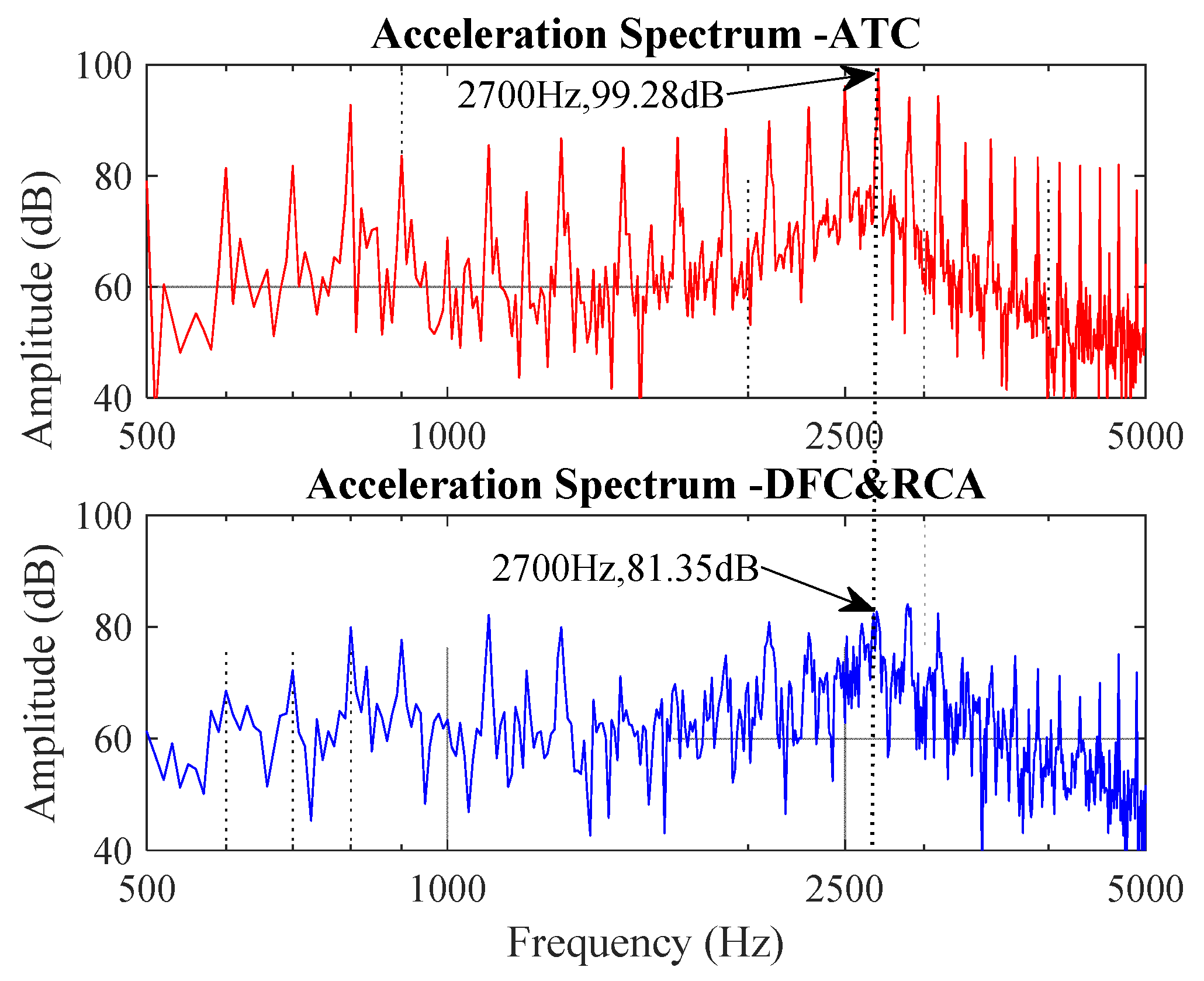
In Figure 11, the corresponding vibration acceleration spectrums are presented. The maximum vibration value near its natural frequency (2660 Hz) presents a reduction of 17.9 dB. Moreover, according to the comparison results, the vibration also has been reduced in a wide frequency range. The spectrum of the measured SPL (sound power level) is presented in Figure 12 showing a reduction of 13.7 dB near the natural frequency.
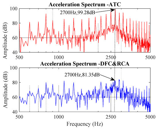
Figure 11.
Experimental results of vibration acceleration at Ω* = 1000 r/min and TL = 2 N∙m.
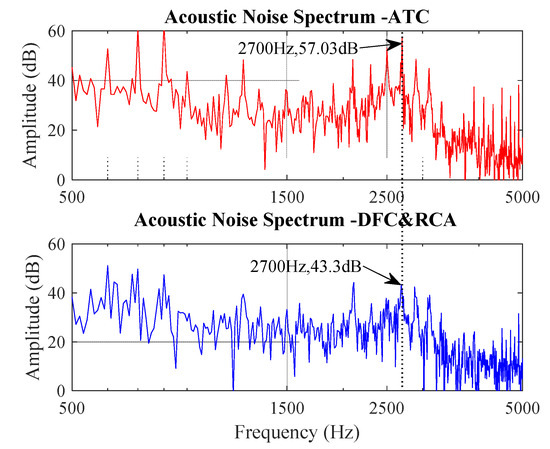
Figure 12.
Experimental results of acoustic noise at Ω* = 1000 r/min and TL = 2 N∙m.
It can be seen that the proposed method DFC&RCA can reduce both the vibration and acoustic noise of the SRM system without sacrificing the efficiency and increasing significant torque ripple under stable condition.
3.2. Transient Condition
In the previous section, the proposed control method is compared to a traditional one (ATC) considering aspects related to vibration, acoustic noise and torque ripple when the speed has reached the steady state. The transient periods when there are sudden changes in the reference speed or load torque are also important if we consider urban driving conditions. Thus, this section investigates the dynamic response of the proposed method under reference speed and load torque variations.
3.2.1. Reference Speed Variation
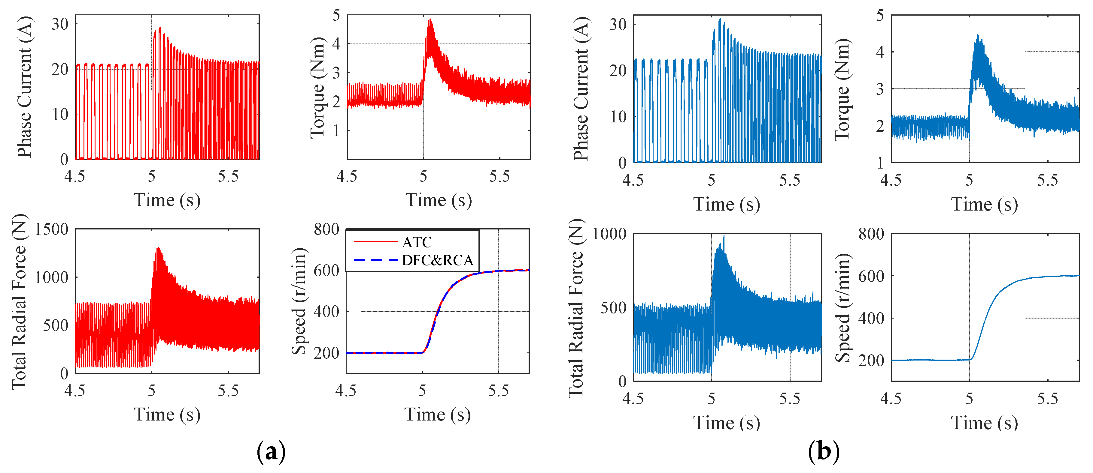
Figure 13 presents the experimental results of ATC and DFC&RCA when the reference speed is increased from 200 r/min to 600 r/min at 5 s with a load torque of 2 N∙m. As shown in this figure, the phase current increases at 5 s when the reference speed changes, so that SRM can provide a higher torque to enable the rotor to catch up with the new reference speed. According to the comparison, the transient period of the speed for both controllers is the same about 0.5 s. And the phase current peak value of DFC&RCA is always bigger than ATC so that to reduce the variation of the radial force.
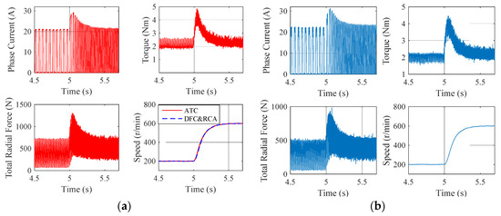
Figure 13.
Transient curves for a step-change in the reference speed from 200 r/min to 600 r/min and TL = 2 N∙m. (a) ATC; (b) DFC and RCA.
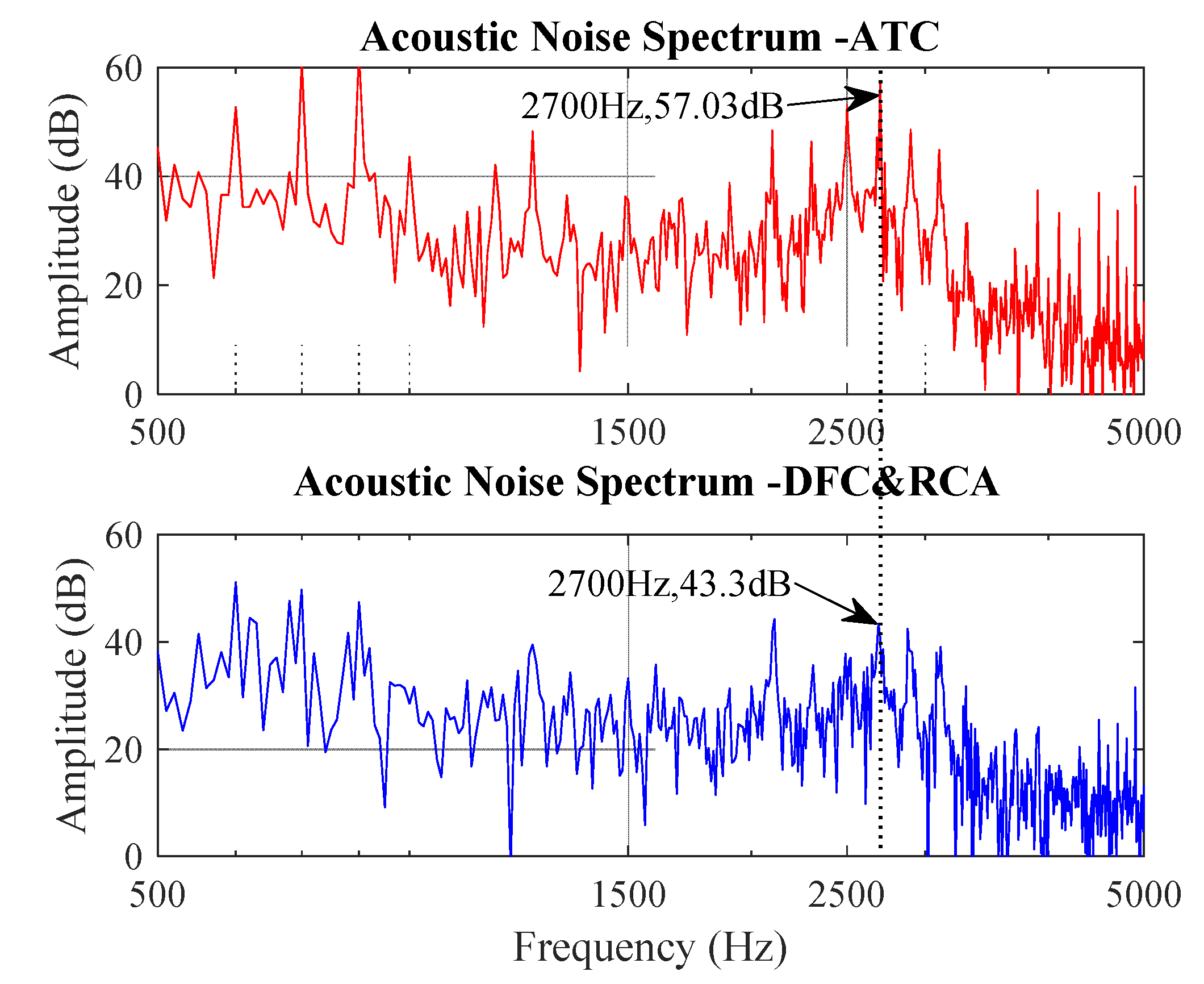
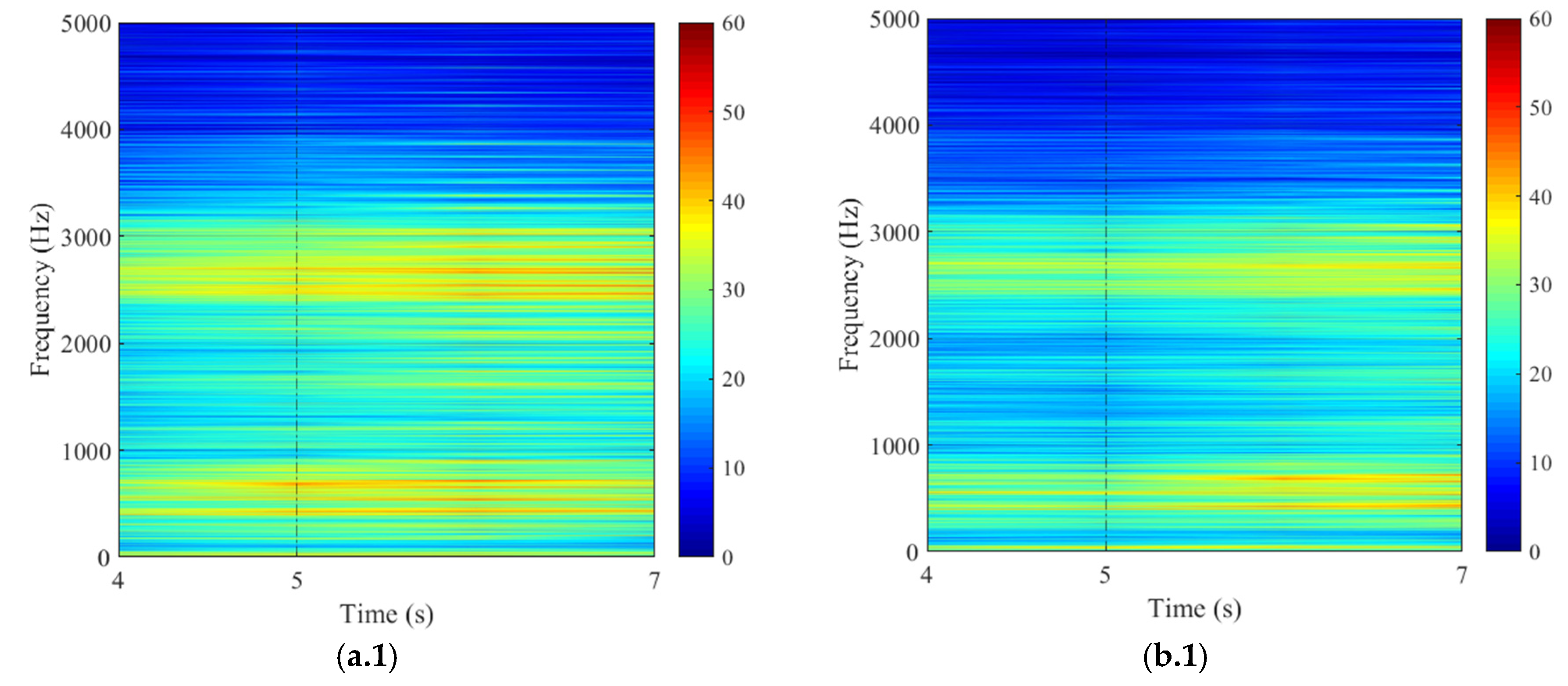
The corresponding acoustic noise measurement results are given in Figure 14. The acoustic noise increases with the increase of the speed. The noises below 700 Hz are mainly from the power supply and MPB. In fact, there are two dominant frequencies for MPB, which are 540 Hz and 670 Hz. And the noise from power supply increases near 400 Hz with current increase. It can be seen that DFC&RCA has always less SPL than the traditional control method (ATC) whenever the speed is stable (before 5 s and after 7 s) or during the transient period (from 5 s to 7 s).
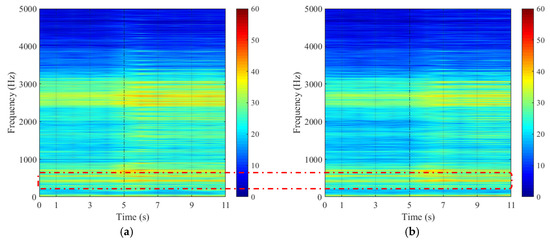

Figure 14.
Experimental sonogram of acoustic noise for a step-change in the reference speed from 200 r/min to 600 r/min and TL = 2 N∙m. (a) Sonogram with ATC; (b) Sonogram with DFC&RCA; (a.1) Partial zoom-in of (a) for the transient period; (b.1) Partial zoom-in of (b) for the transient period.
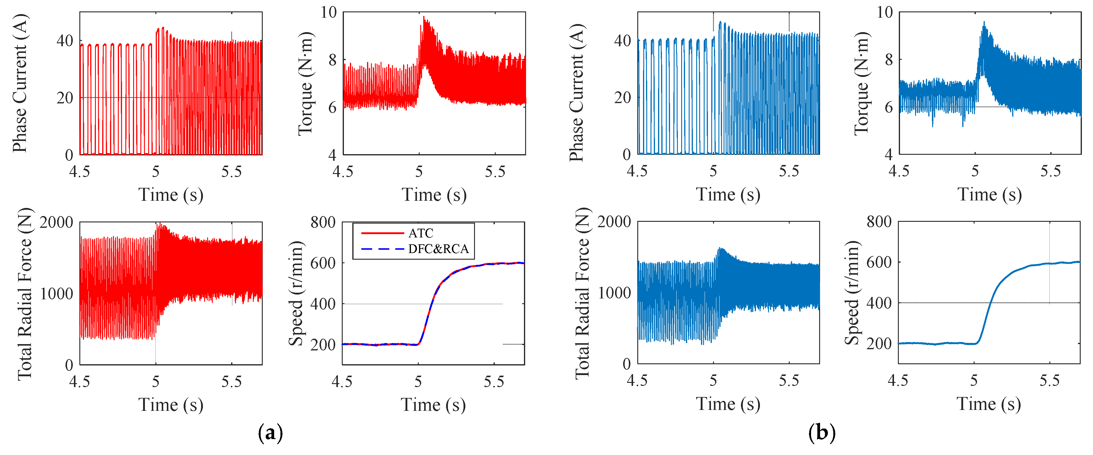
Figure 15 presents the experimental results of ATC and DFC&RCA when the reference speed is increased from 200 r/min to 600 r/min at 5 s with a higher load torque (TL = 6 N∙m). Similar conclusions can be obtained as in the case with a light load of 2 N∙m.
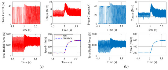
Figure 15.
Transient curve for a step-change in the reference speed from 200 r/min to 600 r/min and TL = 6 N∙m. (a) ATC; (b) FC and RCA.
The corresponding acoustic noise measurement results are given in Figure 16. DFC&RCA also has lower SPL than ATC both in stable and transient period. Comparing Figure 14 with Figure 16, the SPL is higher with a load of 6 N∙m than with a load of 2 N∙m at the same speed. Besides, the noise from the power supply is more serious with an increase of 10 dB when the load torque is added.
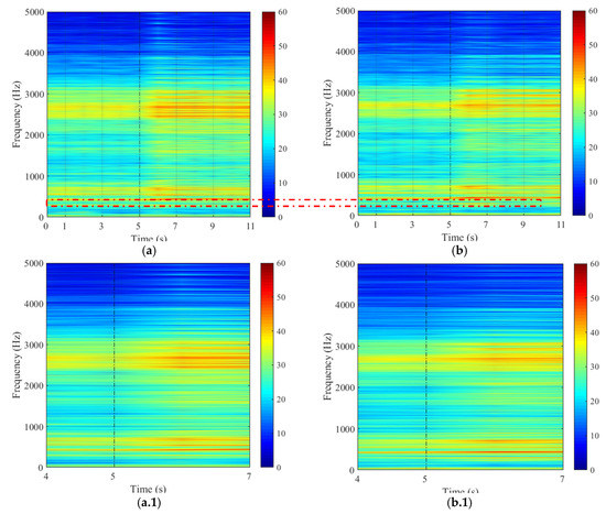
Figure 16.
Experimental sonogram of acoustic noise for a step-change in the reference speed from 200 r/min to 600 r/min and a load torque of 6 N∙m. (a) Sonogram with ATC; (b) Sonogram with DFC&RCA; (a.1) Partial zoom-in of (a) for the transient period; (b.1) Partial zoom-in of (b) for the transient period.
3.2.2. Torque Load Variation
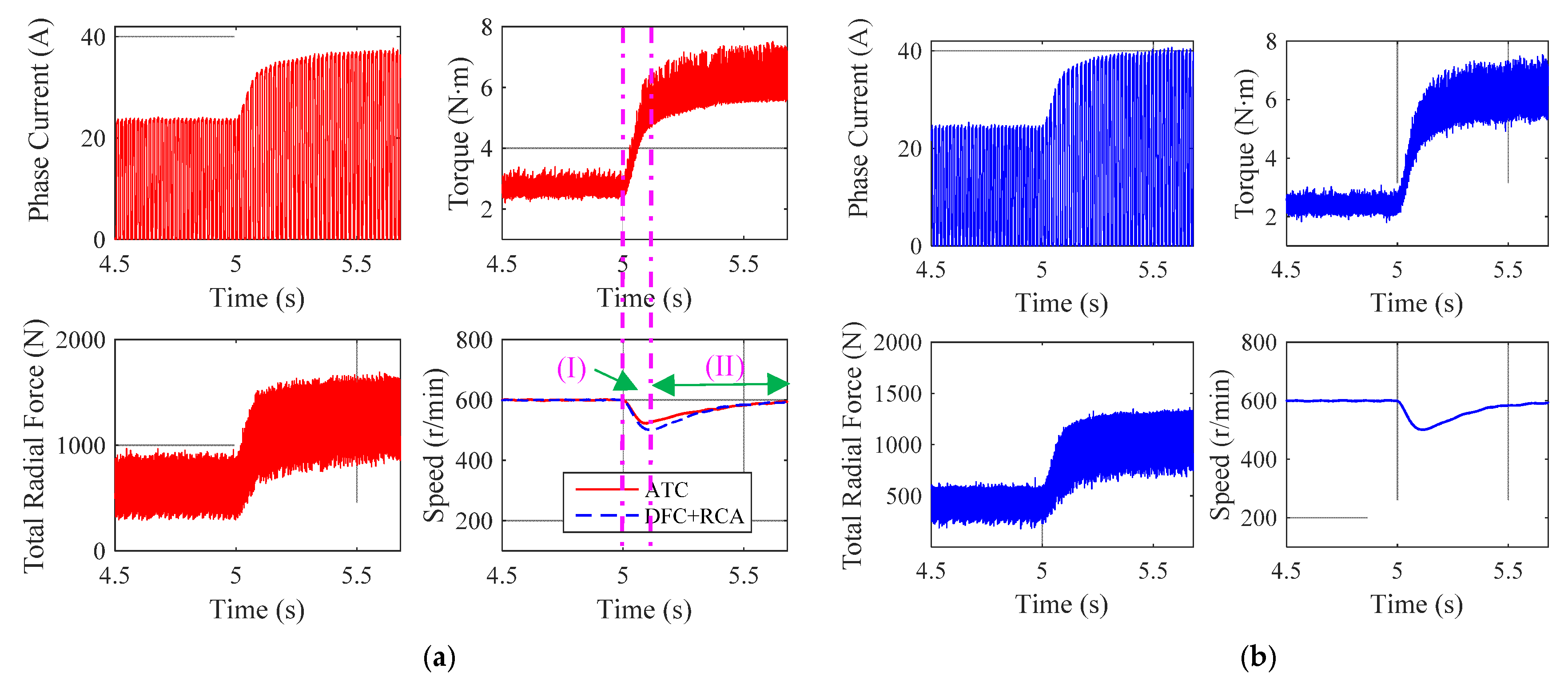
Figure 17 shows the experimental results of ATC and DFC&RCA when the load torque is increased from 2 N∙m to 6 N∙m at 5 s with a reference speed of 600 r/min. As expected, the phase current increases when the load torque is modified, so that SRM provides a higher torque to maintain the same speed. However, there exists a period when the speed is smaller than the reference value. This period consists of two parts: speed decrease part (Figure 17a-I) which is attributed by the lower output mean torque compared to the load torque when the load changes and speed increase part (Figure 17a-II) where the output mean torque is bigger than the load torque so that to enable the rotor speed up to emulate the given reference speed 600 r/min. Even though the minimum actual speed of DFC&RCA is a little smaller that of ATC during this transient period, both control methods assure a closed-loop response time about 0.5 s.
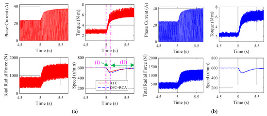
Figure 17.
Transient curves for a step-change in the load torque from 2 N∙m to 6 N∙m at constant reference speed Ω* = 600 r/min. (a) ATC; (b) DFC & RCA.
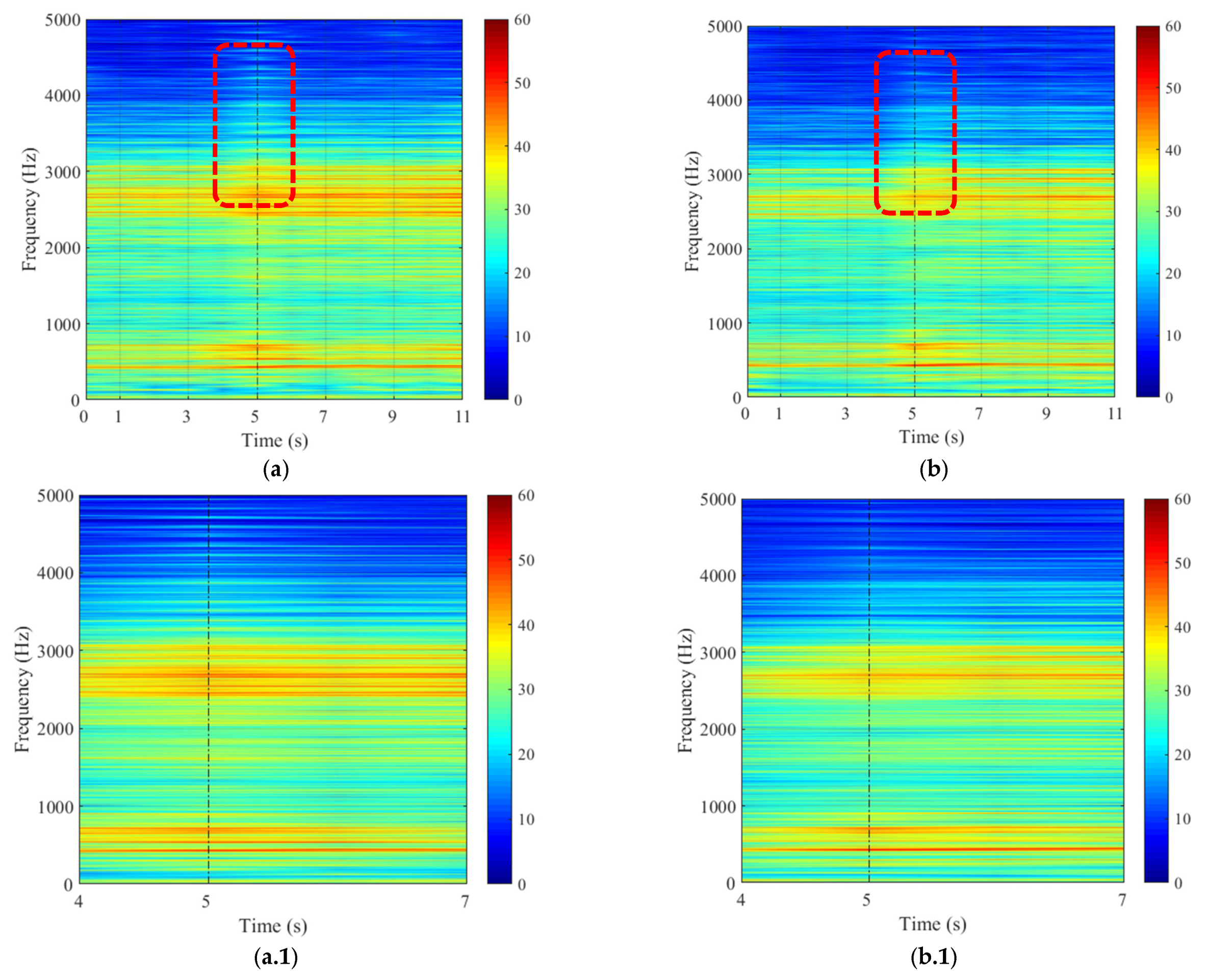
The corresponding acoustic noise measurement results are given in Figure 18. The high-order acoustic harmonics are increased in Figure 18 (red dash line region) at the moment the load torque is increased, this is caused by the increasing current to maintain the reference speed. It can be seen that SPL of both methods near the natural frequency are increased when load torque is increased, however, DFC&RCA has lower SPL than ATC at both steady state and during transients.
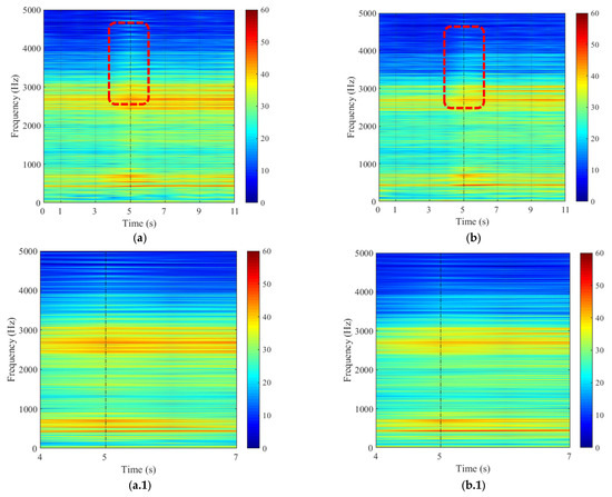
Figure 18.
Experimental sonogram of acoustic noise for a step-change in the load torque from 2 N∙m to 6 N∙m at constant reference speed Ω* = 600 r/min. (a) Sonogram with ATC; (b) Sonogram with DFC&RCA; (a.1) Partial zoom-in of (a) for the transient period; (b.1) Partial zoom-in of (b) for the transient period.
4. Conclusions
In this paper, a method to reduce the vibration and noise of switched reluctance machines is proposed. It is an improved control method based on DFC aiming to reduce the radial force variation, which is the main cause of the vibration and noise source of SRM. An auto-tuning current adaptor is proposed to handle the trade-off between vibration reduction of DFC and torque ripple minimization of ATC. Some experimental results are presented to validate the effectiveness of the proposed method DFC&RCA by comparing it to the traditional control method ATC under both steady state and transient state. Under steady state conditions DFC&RCA is compared to ATC analyzing the vibration, the torque ripple, the efficiency and the acoustic noise. According to the comparison results, the maximum reduction of vibration near the natural frequency is up to 17.9dB without sacrificing the efficiency and without important penalizing the torque ripple. The reduction of maximum SPL near the natural frequency is up to 13.7 dB. Regarding transients, both speed variation with same load torque and load variation with same reference speed are tested. The results show that the proposed method improves the acoustic performance of the SRM and maintains the dynamic response (both methods are with a response time of 0.5s) of it, which proves the potential of the DFC&RCA strategy.
Author Contributions
Conceptualization, M.Z. and I.B.; methodology, M.Z., X.M., I.B., C.V. and H.X.; software, M.Z. and E.B.; validation, M.Z., E.B and H.X.; formal analysis, M.Z. and H.X.; investigation, M.Z., X.M., I.B, C.V. and H.X.; original draft preparation, M.Z.; review and editing, M.Z. and H.X.; supervision, X.M., I.B., and C.V.; funding acquisition, M.Z. and H.X.
Funding
This research was funded by CSC and foundation of Sichuan province No. 2017RZ0055.
Conflicts of Interest
The authors declare no conflict of interest.
References
- Chiba, A.; Kiyota, K.; Hoshi, N.; Takemoto, M.; Ogasawara, S. Development of a Rare-Earth-Free SR Motor with High Torque Density for Hybrid Vehicles. IEEE Trans. Energy Convers. 2015, 30, 175–182. [Google Scholar] [CrossRef]
- Anwar, M.; Husain, I. Radial force calculation and acoustic noise prediction in switched reluctance machines. IEEE Trans. Ind. Appl. 2000, 36, 1589–1597. [Google Scholar]
- Anwar, M.N.I.; Husain, M.S.; Sebastian, T. Evaluation of acoustic noise and mode frequencies with design variations of switched reluctance machines. IEEE Trans. Ind. Appl. 2003, 39, 695–703. [Google Scholar] [CrossRef]
- Gan, C.; Wu, J.; Shen, M.; Yang, S.; Hu, Y.; Cao, W. Investigation of skewing effects on the vibration reduction of three-phase switched reluctance motors. IEEE Trans. Magn. 2015, 51, 1–9. [Google Scholar] [CrossRef]
- Edamura, K.; Miki, I. Design of stator and rotor for noise reduction of SRM. In Proceedings of the 17th International Conference on Electrical Machines and Systems (ICEMS), Hangzhou, China, 22–25 October 2014; pp. 1871–1874. [Google Scholar]
- Kakishima, T.; Kiyota, K.; Nakano, S.; Chiba, A. Pole selection and vibration reduction of Switched Reluctance Motor for hybrid electric vehicles. In Proceedings of the IEEE Conference and Expo Transportation Electrification Asia-Pacific (ITEC Asia-Pacific), Beijing, China, 31 August–3 September 2014; pp. 1–4. [Google Scholar]
- Besbes, M.; Picod, C.; Camus, F.; Gabis, M. Influence of stator geometry upon vibratory behavior and electromagnetic performances of switched reluctance motors. IEE Proc. Electr. Power Appl. 1998, 145, 462–468. [Google Scholar] [CrossRef]
- Castano, S.M.; Bilgin, B.; Fairall, E.; Emadi, A. Acoustic noise analysis of a high-speed high-power switched reluctance machine: Frame effects. IEEE Trans. Energy Convers. 2016, 31, 69–77. [Google Scholar] [CrossRef]
- Yasa, Y.; Tekgun, D.; Sozer, Y.; Kutz, J.; Tylenda, J. Effect of distributed airgap in the stator for acoustic noise reduction in switched reluctance motors. In Proceedings of the IEEE Applied Power Electronics Conference and Exposition (APEC), Tampa, FL, USA, 26–30 March 2017; pp. 633–639. [Google Scholar]
- Mademlis, C.; Kioskeridis, I. Performance optimization in switched reluctance motor drives with online commutation angle control. IEEE Trans. Energy Convers. 2003, 18, 448–457. [Google Scholar] [CrossRef]
- Boukhobza, T.; Gabsi, M.; Grioni, B. Random variation of control angles, reduction of SRM vibrations. In Proceedings of the IEEE International Electric Machines and Drives Conference (Cat. No.01EX485), Cambridge, MA, USA, 17–20 June 2001; pp. 640–643. [Google Scholar]
- Wu, C.Y.; Pollock, C. Time domain analysis of vibration and acoustic noise in the switched reluctance drive. In Proceedings of the Sixth International Conference on Electrical Machines and Drives (Conf. Publ. No. 376), Oxford, UK, 8–10 September1993; pp. 558–563. [Google Scholar]
- Mininger, X.; Lefeuvre, E.; Gabsi, M.; Richard, C.; Guyomar, D. Semiactive and active piezoelectric vibration controls for switched reluctance machine. IEEE Trans. Energy Convers. 2008, 23, 78–85. [Google Scholar] [CrossRef]
- Ojeda, X.; Mininger, X.; Gabsi, M. An active piezoelectric absorber for vibration control of electrical machine. In Proceedings of the IEEE International Conference on Industrial Technology (ICIT), Cape Town, South Africa, 25–28 February 2013; pp. 234–241. [Google Scholar]
- Hofmann, A.; Al-Dajani, A.; Bösing, M.; De Doncker, R.W. Direct instantaneous force control: A method to eliminate mode-0-borne noise in switched reluctance machines. In Proceedings of the International Electric Machines & Drives Conference, Chicago, IL, USA, 12–15 May 2013; pp. 1009–1016. [Google Scholar]
- Annegret, K.H.; Hofmann, A.; De Doncker, R.W. Direct instantaneous torque and force control: A control approach for switched reluctance machines. IET Electr. Power Appl. 2017, 11, 935–943. [Google Scholar]
- Takiguchi, M.; Sugimoto, H.; Kurihara, N.; Chiba, A. Acoustic noise and vibration reduction of SRM by elimination of third harmonic component in sum of radial forces. IEEE Trans. Energy. Convers. 2015, 30, 883–891. [Google Scholar] [CrossRef]
- Bayless, J.; Kurihara, N.; Sugimoto, H.; Chiba, A. Acoustic noise reduction of switched reluctance motor with reduced RMS current and enhanced efficiency. IEEE Trans. Energy Convers. 2016, 31, 627–636. [Google Scholar] [CrossRef]
- Furqani, J.; Kawa, M.; Kiyota, K.; Chiba, A. Current Waveform for Noise Reduction of a Switched Reluctance Motor Under Magnetically Saturated Condition. IEEE Trans. Ind. Appl. 2018, 54, 213–222. [Google Scholar] [CrossRef]
- Sreekumar, T.; Jiji, K.S. Comparison of Proportional-Integral (PI) and Integral-Proportional (IP) controllers for speed control in vector controlled induction motor drive. In Proceedings of the 2nd International Conference on Power, Control and Embedded Systems, Allahabad, India, 17–19 December 2012; pp. 1–6. [Google Scholar]
- Inderka, R.B.; De Doncker, R.W. DITC-direct instantaneous torque control of switched reluctance drives. IEEE Trans. Ind. Appl. 2003, 39, 1046–1051. [Google Scholar] [CrossRef]


© 2019 by the authors. Licensee MDPI, Basel, Switzerland. This article is an open access article distributed under the terms and conditions of the Creative Commons Attribution (CC BY) license (http://creativecommons.org/licenses/by/4.0/).