Article

Cogging Torque Reduction and Offset of Dual-Rotor Interior Permanent Magnet Motor in Electric Vehicle Traction Platforms

1
Department of Electrical Engineering, Chonnam National University, 77 Youngbong-ro, Buk-gu, Gwangju 61186, Korea
2
EV Components & Materials R&D Group, Korea Institute of Industrial Technology, 6 Cheomdan-gwagiro 208 beon-gil, Buk-gu, Gwangju 61012, Korea
3
Robotics and Virtual Engineering, Korea University of Science and Technology, Daejeon 34113, Korea
4
Department of Mechanical Engineering, Chonnam National University, 77 Youngbong-ro, Buk-gu, Gwangju 61186, Korea
*
Author to whom correspondence should be addressed.
Energies 2019, 12(9), 1761; https://doi.org/10.3390/en12091761
Submission received: 12 April 2019 / Revised: 7 May 2019 / Accepted: 7 May 2019 / Published: 9 May 2019

Abstract

:
Recently, various methods have been proposed to increase the output power density of a driving motor applied to an electric vehicle. One such method is to design a structure with two motor rotors. High output density can be obtained by applying the dual rotor to the motor. However, this increases the cogging torque, which can cause high noise and vibration. In this paper, we proposed a method for reducing the cogging torque by adjusting the angle between the magnet and the dual rotor, as well as a novel method for reducing the cogging torque by angular adjustment of the slot opening based on electromagnetic field analysis. In addition, the design was implemented by applying a split core to increase the ease of manufacturing and the dot rate in the motor. We believe that high cogging torque, which is a disadvantage of dual rotor motors, can be lowered by the methods proposed in this paper. The results of this study are expected to be applicable to electric vehicles that require high output power density.

1. Introduction

The environmentally friendly electric car market is continuously expanding on a global scale and the automotive industry is engaged in the development of motors with high power density for application to electric vehicles. In particular, the development of traction motors, which are critical to electric vehicles, is in focus. Recently, a method for increasing the output density by using a structure with dual rotors was proposed. However, a drawback of this method was that the cogging torque was doubled, resulting in high noise and vibration. This makes the structure unsuitable for electric vehicles, as they require low noise and low vibration. Therefore, research on reducing the noise and vibration in driving motors applied to electric automobiles are being actively conducted. Yet, there has been no active research on reducing vibrations and noise when using dual rotors. Therefore, this paper proposed a cogging torque canceling design suitable for dual rotor motor.
The basic structure was based on an interior permanent magnet (IPM) motor. Motors with an IPM structure have been applied mostly to electric vehicle drive motors because they have high output density and high efficiency [1,2,3].
The reason for the high output density and the high efficiency of the IPM synchronous motor is that it utilizes reluctance torque as well as magnetic torque and has a structure wherein permanent magnets are embedded inside the rotor [4,5]. This structure generates two torque components—one due to the permanent magnet and another due to the difference in the d-q-axis magnetic reluctance—thereby ensuring high output density. Therefore, the IPM motor is suitable for practical applications requiring high output density.
In the dual rotor motor, the permanent magnets are placed inside and outside of the split cores to form a magnetic circuit between the inner and outer permanent magnets and the yoke of the rotor. This allows the complete division of the split core so that individual coil windings can be applied to significantly enhance the productivity of the split cores and the output of the motor [6,7,8,9,10].
Despite its advantages, the dual rotor IPM motor generates twice the cogging torque; moreover, the cogging torque and torque ripple are larger than in the conventional single-rotor motor. Therefore, reduction of the cogging torque and torque ripples of the IPM motor are important. The electromagnetic vibration sources of the IPM motor include the non-uniformity of the normal force due to rotor eccentricity, axial thrust variation due to axial eccentricity, commutation torque ripples, and cogging torque according to the driving system [11,12]. The IPM motor can achieve high magnetic flux density in the air gap and high output because the lengths of the mechanical and magnetic air gaps are identical; however, the relatively high cogging torque should be reduced as much as possible in the design stage because it has significant effects on the noise and vibration of the motor [13,14]. Therefore, the reduction of cogging torque to lower the vibrations is an important research topic.
Consequently, active research is underway to reduce vibration and noise in IPM motors. Many studies have published methods to reduce the cogging torque and torque ripples, such as adjustment of layout, adjustment of slot and tooth width, application of permanent magnet skew, application of a supporting tool on the tooth, use of slotless armature, and the application of notches [15,16]. Most of the methods used to reduce cogging torque and torque ripples implemented in other studies were electromagnetic methods, which reduced the cogging torque and torque ripples but also reduced the effective flux, thus lowering the output and efficiency. Mechanical methods reduce the effective flux much less than the electromagnetic methods. Thus, they facilitate the operation of high efficiency, high power motors.
Therefore, in this paper, we have proposed a method to reduce the generation of cogging torque, which is the biggest weakness of the dual rotor type BLDC motors. First, we verified the well-known method for reducing the cogging torque by optimizing the shapes of the stator and rotor. Secondly, we examined the method for reducing the cogging torque by mechanically changing the magnet arrangement. In order to overcome the difficulty of precisely matching the arrangement of the magnets, we proposed a new method for reducing the cogging torque by adjusting the angle of the slot opening. As a general method, we proposed the minimization of cogging torque by adjusting the slot opening, the length of the magnet, and the distance between the magnet and the end of the rotor, by modifying the stator. In addition, we examined the arrangement of the magnets and finally proposed a cogging torque reduction method based on the adjustment of the slot opening angle.
In Section 2, the cogging torque equation and the IPM motor design flow are explained. In Section 3, the analytical model is constructed by deriving the specifications of the electromagnetic field analysis model through experiments, and the analysis and experimental methods are described. In Section 4, the cogging torque is minimized through experiments, and the optimal design of the cogging torque is analyzed through electromagnetic field analysis. Finally, Section 5 summarizes the conclusions.

2. Theory

2.1. Governing Equations

The governing equations based on the d- and q-axis current control of the IPM consisting of three-phase windings and permanent magnets in the rotor are described here. First, the voltage equations are expressed as follows:
v d s = R s i d s + d λ d s d t ω r λ q s
v q s = R s i q s + d λ q s d t ω r λ d s
where v d and v q are the independent power sources of the virtual d-axis and q-axis coils of the stator.
In the voltage equations, the interlinkage flux of the d-axis and q-axis, λ d s and λ q s , are expressed as follows:
λ d s = L d s i d s + Φ f
λ q s = L q s i q s
The interlinkage flux of the d-axis includes the component of the permanent magnet. Here, the mechanical output and torque can be determined by excluding the stator copper loss and magnetic field energy change from the power expressed as a three-phase voltage and current relation as follows:
P m = 3 2 [ ω r Φ f i q s + ω r ( L d s L q s ) i d s i q s ]
T e = P 2 × 3 2 [ Φ f i q s + ( L d s L q s ) i d s i q s ]
The magnetic torque due to the interaction between the interlinkage flux of the permanent magnet and the q-axis current and the reluctance torque due to the difference in inductance can be distinguished from Equation (6) [17,18,19].

2.2. Cogging Torque and Characteristic Equation

The cogging torque is a non-uniform torque of the stator, which is inevitably generated in a motor using a permanent magnet. It represents the radial torque, which tends to move to the equilibrium state where the magnetic energy of the motor is the lowest. Because the cogging torque is a change in energy resulting from the rotation of the motor rotor, it can be determined by the partial differentiation of the internal energy of the driving motor by the rotor position angle of the synchronous motor as follows:
T C o g ( α ) = Δ W ( α ) Δ ( α )
where TCog is the cogging torque, Δ W ( α ) is the change in energy, and Δ ( α ) is the rotation of the rotor.
W α = 1 2 μ V B 2 d V
In Equation (8), B is the flux density and μ the permeability.
B = G ( θ , z ) · B ( θ , α )
In Equation (9), G(θ, z) is a function of the air gap permeance and B(θ, α) is the air gap flux density. θ is the angle at the circumference and α is the rotation angle. By substituting Equation (9) into Equation (8), we got
W ( α ) = 1 2 μ [ G ( θ , z ) 2 · B 2 ( θ , α ) ] d V = 1 2 μ 0 0 L s R 1 R 2 0 2 π G 2 ( θ , z ) · B 2 ( θ , α ) r d θ d r d z = L s 4 μ ( R 2 2 R 1 2 ) 0 2 π G 2 ( θ , z ) · B 2 ( θ , α ) d θ ,
where μ 0 is the permeability of air, L s is the stacking length, and R is the radius of the stator. R 1 is the internal diameter of the rotor and R 2 is its external diameter.
When G 2 ( θ , z ) and B2(θ, α) in Equation (4) were expanded into the Fourier series and Equation (1) was solved by using the orthogonality of the trigonometric function, Equation (10) could be written as
W ( α ) = L s 4 μ 0 ( R 2 2 R 1 2 ) [ n = 0 G n N L B n N L 0 2 π c o s n N L θ cos n N L ( θ + α ) d θ ] = L s 4 μ 0 ( R 2 2 R 1 2 ) n = 0 G n N L B n N L cos ( n N L α ) π ,
where N L is the least common multiple of the number of poles of the rotor and the number of slots of the stator.
In the final analysis, the cogging torque was expressed as the partial differentiation of the air gap energy by the rotation angle of the rotor from Equation (11), as follows [20,21,22]:
T C o g ( α ) = L s π 4 μ 0 ( R 2 2 R 1 2 ) n = 0 G n N L B n N L n N L s i n n N L α
As can be seen from Equation (12), the cogging torque was determined by the values of G n N L and B n N L .

3. Dual Rotor Modeling

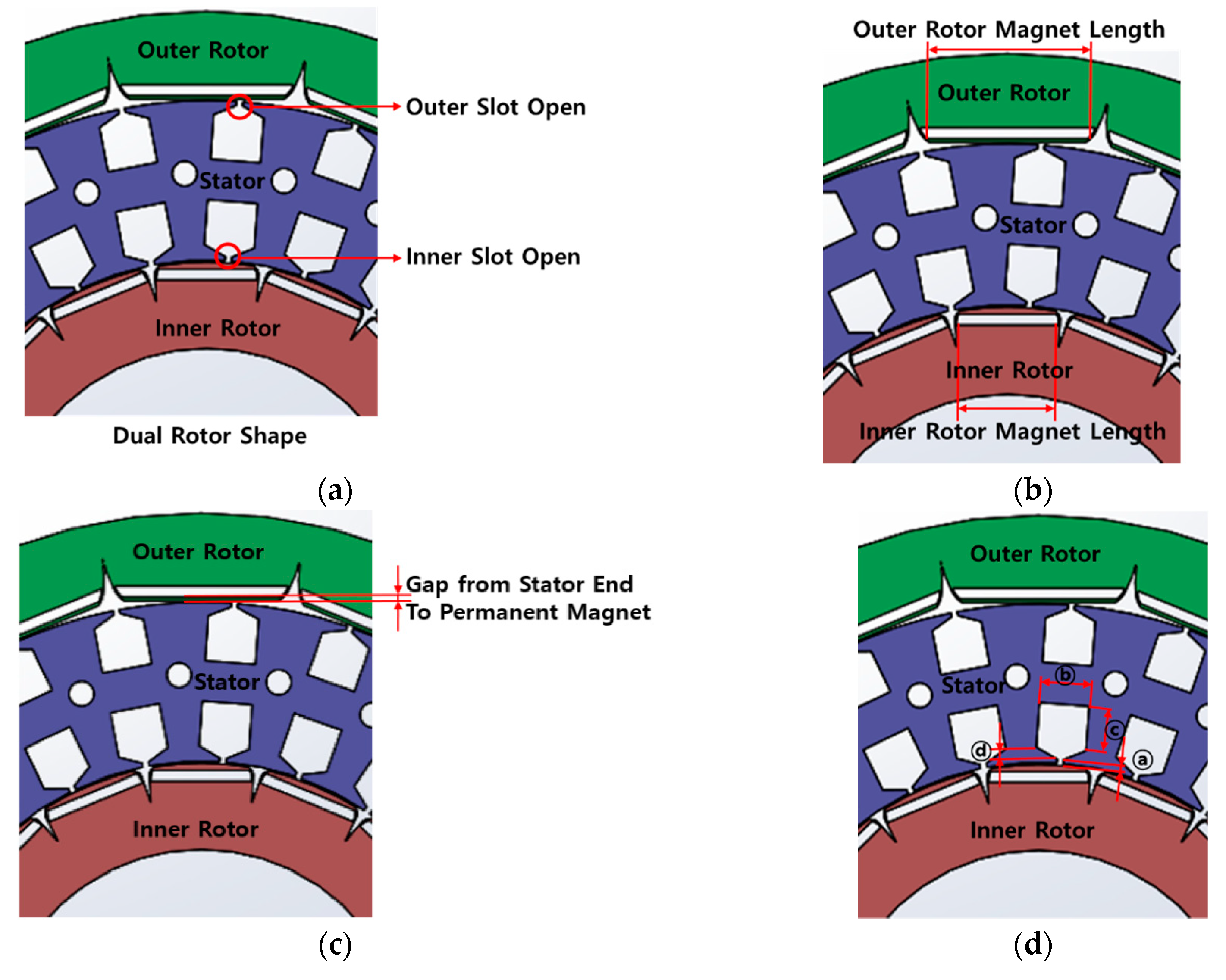
3.1. Machine Topology

Figure 1 shows the results of the modeling and electromagnetic field analysis conducted using the electromagnetic analysis tool “JMAG” (Ver. 14.1). The parameters were fixed for analyzing the cogging torque, and the results of the electromagnetic field analysis were derived. Figure 1 shows the structure of the dual rotor. Winding is applied to the yoke rather than to the slot to minimize the slot opening, as in the conventional method, and the split core is adopted. This enables a structure in which winding can be easily applied to at least 60% of the area in one slot. Owing to the difference in circumference between the inner and outer rotors, magnets of different strengths were applied for the inner and outer rotors in the modeling (Outer Rotor: N35SH, Inner Rotor: N45SH). A magnet of higher grade was used in the inner rotor, as it could accommodate a smaller magnet, whereas a magnet of lower grade was used in the outer rotor, as it could accommodate a larger magnet.

3.2. Design Specifications of Dual Rotor IPM Motor

The slot and pole number combination of the dual rotor IPM motor were selected after analyzing the back EMF value by applying 2-pole 3-slot scale combinations. The 8-pole 12-slot, 16-pole 24-slot, and 24-pole 36-slot combinations were compared through electromagnetic field analysis. The comparison results of the three combinations found that the 16-pole 24-slot combination resulted in back EMF with sinusoidal waveform. Therefore, 16-pole 24-slot was selected as the final design specification.
It can be seen in Figure 2a,c that the back EMF waveforms with the 8-pole 12-slot and 24-pole 36-slot combinations were irregular whereas the back EMF waveform with the 16-pole 24-slot combination, shown in Figure 1b, was sinusoidal.
Table 1 shows the model design specifications of the dual rotor IPM motor used in the analysis. The output of the motor was 20 kW and the combination of 16 poles and 24 slots, which resulted in back EMF with sinusoidal waveform (Figure 1), was selected. The current range was set to 72 A_rms and the rated voltage was 310 V.
According to the energy method, the cogging torque is the change in static magnetic energy when the motor rotates. Therefore, we compared the results of cogging torque obtained from electromagnetic field analysis of four methods, including the stator and rotor shape design method, which is the general method proposed in many studies.
This study performed the following four analyses: (i) Analysis of the slot opening adjustment in the stator, (ii) analysis of the magnet length, (iii) analysis of the cogging torque according to the gap between the magnet and the stator tip, and (iv) analysis of the stator shape.
It was expected that the cogging torque could be reduced by examining the energy changes connected to the stator and rotor based on the four analyses mentioned above. In addition, a method for reducing the cogging torque by adjusting the angle between the magnet and the inner and outer rotors, which was the method proposed in this paper, was examined. The adjustment of the slot opening angle in the stator is a simple method that can be widely applied because it involves the modification of the core shape.
Based on the results, we verified the method for reducing the cogging torque, including the recently studied method for controlling the cogging torque through the magnet angle, and proposed a method for reducing the cogging torque according to the angle of the stator slot opening, which is easy to adopt in manufacturing and can effectively reduce the cogging torque.

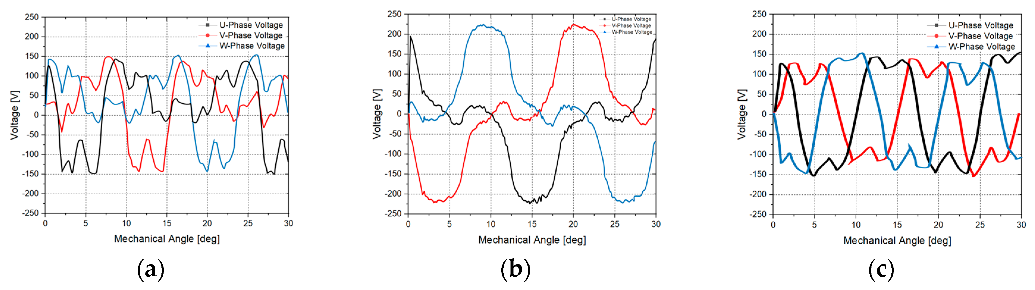
3.3. Experimental Methods for Cogging Torque Analysis

Electromagnetic field analysis was performed through “JMAG” (Ver. 14.1) and the characteristics of the cogging torque were derived in order to perform a comparative analysis. The data values were compared using electromagnetic field software keeping one parameter fixed at a time. Figure 3 examines the method used to reduce the cogging torque by modifying the stator and rotor geometries. The four general methods were analyzed similar to the proposed method. The dual rotor IPM motor had outer and inner slots of the stator and Figure 3a depicts how the optimal design value was derived by adjusting the lengths of the outer and inner slot openings. Figure 3b shows the comparison of the cogging torques by changing the lengths of the permanent magnets in the outer and inner rotors. Figure 3c shows the analysis of the output and cogging torque by changing the distance between the magnet and the stator tip. The output and cogging torque have a close linear relationship with the distance between the magnet and the stator. Figure 3d shows the derivation of the design value at which the cogging torque was the lowest by modifying the detailed design values of the inner stators. The cogging torque optimization method was proposed based on the four analysis methods in Figure 3.

4. Comparison and Analysis Results

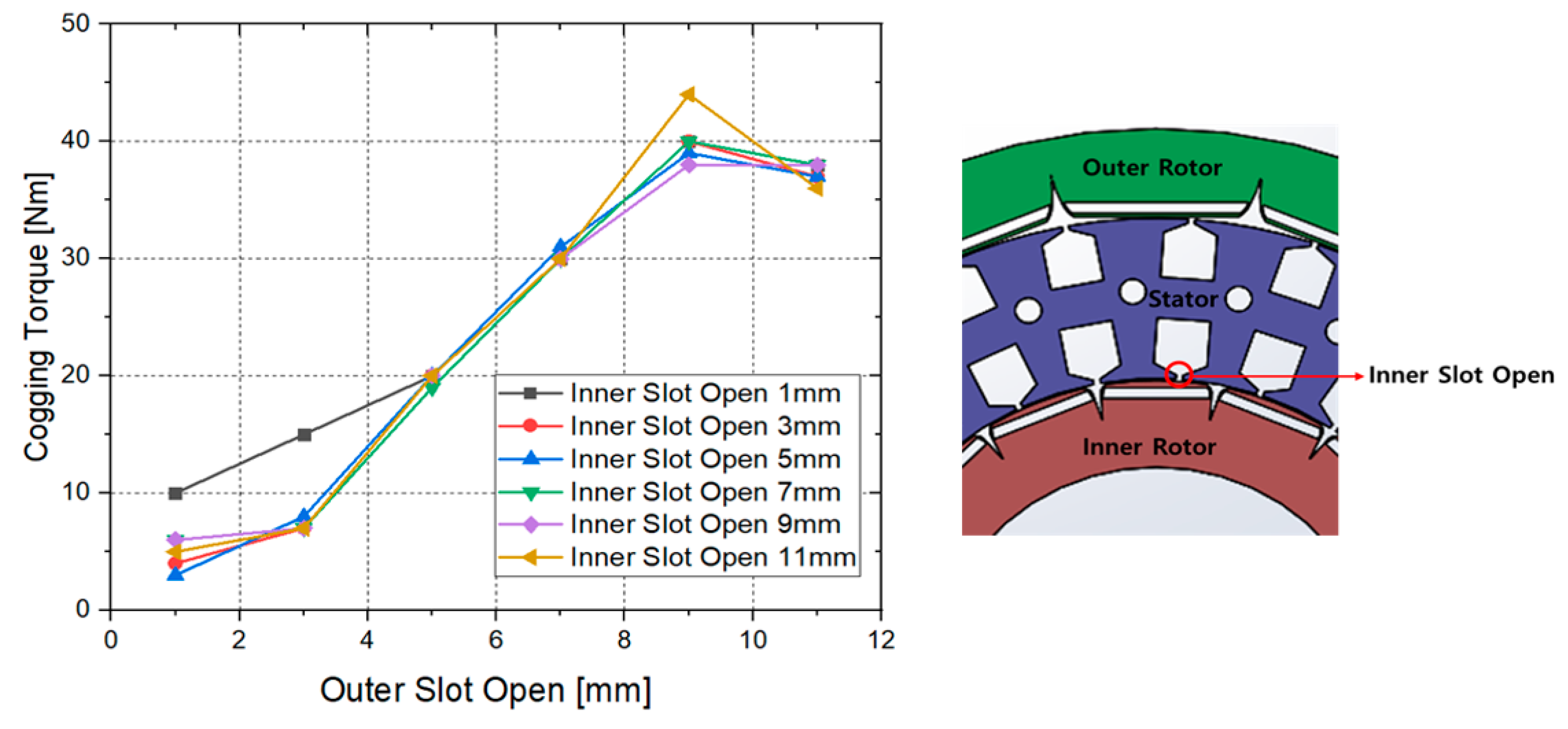
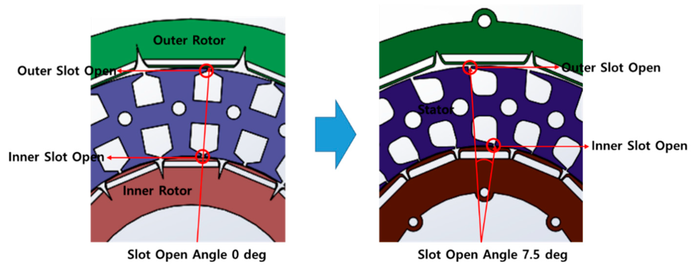
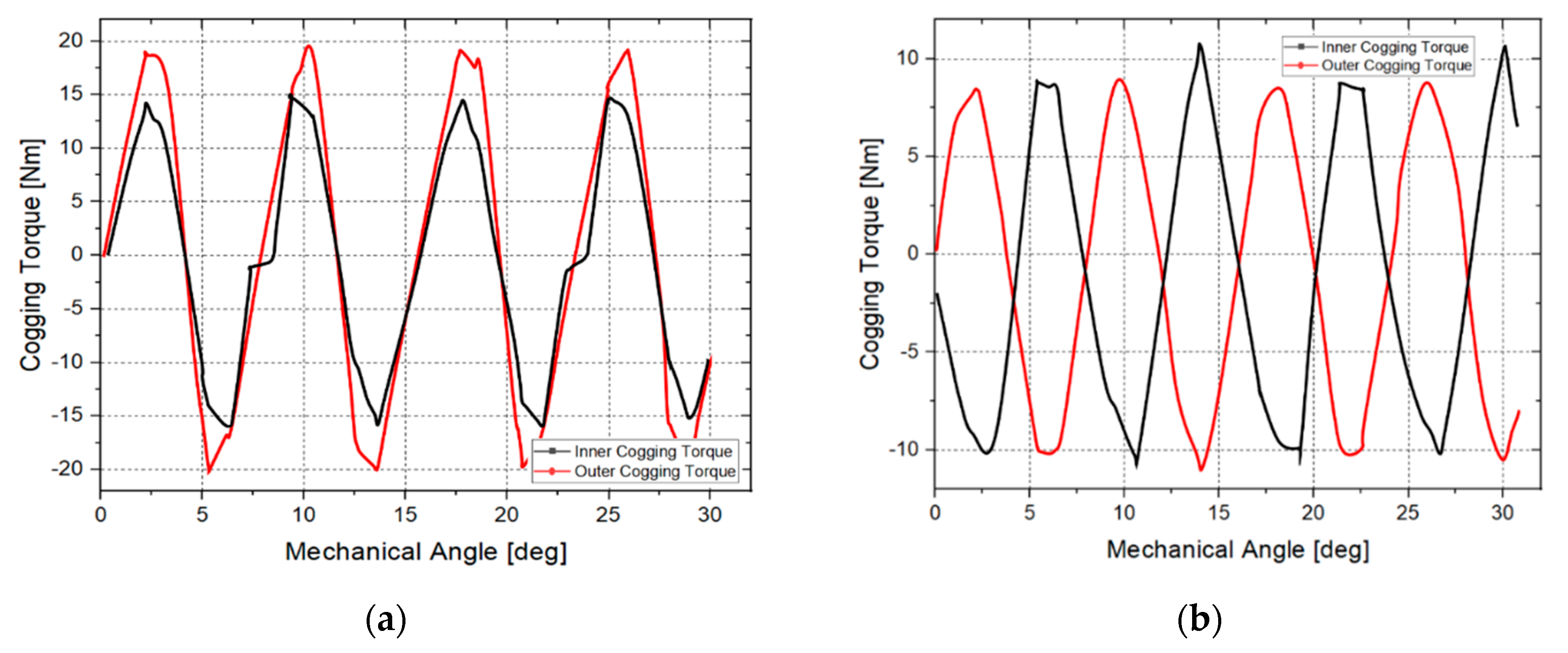
4.1. Cogging Torque Analysis of Dual Rotor Stator Slot Opening Length

The cogging torque was analyzed at the rated velocity of 2200 rpm by adjusting the stator slot opening. An analysis of the graph in Figure 4 reveals the decreasing trend of the cogging torque as the slot opening became smaller. As shown on Figure 4, the cogging torque of the inner rotor was 3 Nm when the slot opening was 1 mm and 36 Nm when the slot opening was 11 mm, which was a difference of 33 Nm.
The best value of the cogging torque was achieved when the inner slot opening was 1 mm and the outer slot opening was 5 mm. An analysis of the graph in Figure 4 revealed the decreasing trend of the cogging torque as the slot opening became smaller.

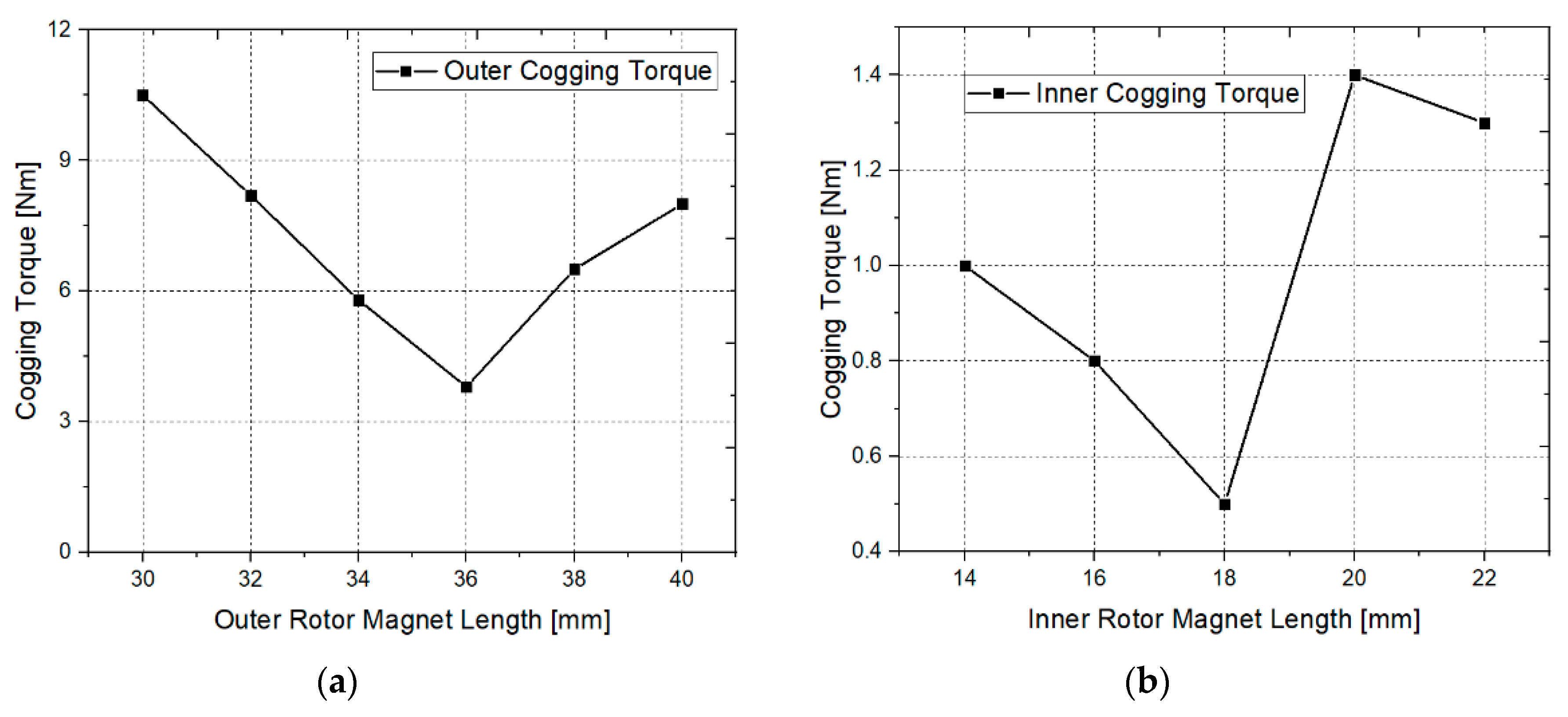
4.2. Analysis of Cogging Torque According to the Dual Rotor Magnet Length

In general, the magnetic flux increases as the magnet length increases. Thus, when the magnet length decreased, the torque decreased due to the reduced magnetic flux, but this significantly affected the output. Furthermore, the magnet length affects the cogging torque. Therefore, the appropriate cogging torque should be derived without reducing the output.
Figure 5 shows the cogging torque analysis results according to the magnet lengths of the inner and outer rotors. Figure 5a shows the variation in the outer cogging torque with a change in the outer rotor magnet length. It can be seen from the figure that the cogging torque was 3.8 Nm at the outer rotor magnet length of 36 mm and 10.5 Nm at 30 mm, which was a difference of 6.7 Nm. Figure 5b shows the analysis of the inner cogging torque according to the inner rotor magnet length. It can be seen from the figure that the cogging torque was 0.5 Nm at the inner rotor magnet length of 18 mm and 1.3 Nm at 22 mm, which was a difference of 0.8 Nm.
The results of Figure 5 are outlined in Table 2. In the early stage, the magnet length for the outer rotors increased from 30 to 40 mm and the inner rotor increased from 14 to 22 mm in increments of 2 mm. The inner rotor magnet length was analyzed up to 22 mm because of the limitation of the model. The experimental results showed that the cogging torque was the lowest at a magnet length of 36 mm for the outer rotor and 18 mm for the inner rotor.
The results shown in Figure 5 are outlined in Table 3. In Table 2, the optimal value was found by increasing the magnet length in increments of 2 mm. In Table 3, the optimal design value was derived by subdividing the optimal results and increasing the magnet length in increments of 0.5 mm. The lowest cogging torque of 3.6 Nm was observed at the outer rotor magnet length of 36.5 mm, and that of 0.4 Nm was observed at the inner rotor magnet length of 17.5 mm.

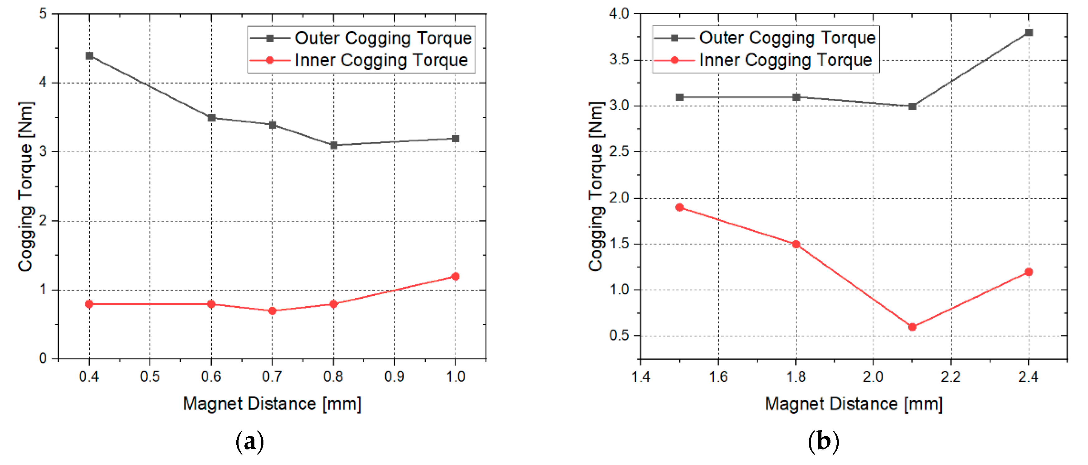
4.3. Analysis of Cogging Torque According to the Distance between Magnet and Rotor Tip

Figure 6a shows the cogging torque values against the distance between the magnet and the stator of the outer rotor. In the outer rotor, the cogging torque was the lowest (3.1 Nm) at a distance of 0.8 mm between the magnet and the rotor tip. Figure 6b shows the cogging torque values against the distance between the magnet and the stator of the inner rotor. The lowest cogging torque value of 0.6 Nm was observed at a distance of 2.1 mm.

4.4. Analysis of Cogging Torque According to Stator Shape

The representative method for reducing the cogging torque in the stator is to apply a skew to the stator. However, this method cannot be applied to a split core. Furthermore, it requires an additional process that decreases the output power density of the motor by reducing the occupation ratio of the winding, which increases the motor production cost. Therefore, it is meaningful to reduce the cogging torque by optimizing the stator shape without applying the skew.
The distances of four different spots, named (a) to (d), were adopted in this study to optimize the stator shape, and they are shown in Figure 7. In distance of (a) shown in Figure 8a, the inner and outer slot lengths of the stator were changed to the same value, which resulted in the inner cogging torque of 0.8 Nm and the outer cogging torque of 2.7 Nm at a distance of 0.9 mm. The lowest cogging torque was obtained when these two cogging torque values were added together. The lowest inner cogging torque was obtained at a distance of 0.5 mm and the lowest outer cogging torque was obtained at a distance of 0.9 mm.
In distance of (b) shown in Figure 8b, the outer cogging torque was 2.1 Nm and the inner cogging torque was 0.8 Nm at a distance of 9.5 mm. However, the adjustment of length in No. 2 is linked to the stator area and this area is analyzed by a factor associated with the occupation ratio of the winding.
In distance of (c) shown in Figure 8c, the outer cogging torque was 2.1 Nm and the inner cogging torque was 1.0 Nm at a distance of 10.5 mm. The length change in No. 3 was also related to the winding area. The largest winding area must be used to produce a motor with a high output.
In distance (d) shown in Figure 8d, the sum of the cogging torques was the lowest at 1.8 mm, where the outer cogging torque was 1.75 Nm and the inner cogging torque was 1.3 Nm.

4.5. Analysis of Cogging Torque According to the Magnet Angles of Inner and Outer Rotors

Figure 9 illustrates the core functionality of this paper, which was the method for reducing the cogging torque by applying an angle difference between the outer and inner magnets. Furthermore, the optimal angle was determined through an experiment that offset the cogging torques by varying the angles of the slot opening centers of the outer and inner rotors based on the detailed structure design according to the shape dimensions.
The plot in Figure 9 shows the analysis of the cogging torque according to the magnet angle. The cogging torques in the inner and outer rotors are shown in the figure. The results of adding the inner and outer cogging torques are also shown in Figure 8. The cogging torque of 45 Nm was generated at the analytical step electrical angle of 5°.
Figure 10, shows the method proposed in this study to reduce the cogging torque by adjusting the angle of the slot opening. Recently, Figure 9 was reported in some studies; however, Figure 10 suggests a method for reducing the cogging torque by adjusting the angle of the slot opening rather than by magnet angle control through electromagnetic field analysis.
The plot of Figure 10 shows the electromagnetic field analysis results obtained by adjusting the angles of the inner and outer rotor magnets. From the analysis, it was verified that the cogging torques generated in the internal and external rotors alternated when the machine angle was 5.62°; the corresponding design is shown in Figure 10. The net cogging torque is also shown in this figure. The analysis of the adjustment of the mechanical angle between the inner and outer rotor magnets confirmed the intersection of the inner and outer cogging torques, as shown in Figure 9. The model that considerably reduced the cogging torque can be achieved by adding alternating waveforms at the magnet angle of 5.62°.
Figure 11 shows how to adjustment of stator slot opening angle. The method to show the cogging cancellation by changing the angle between the slot opening centers of the outer and inner rotors was verified by electromagnetic field analysis. In the case of ∠0°, cogging cancellation did not occur, similar to the case where only the slot opening was adjusted; however, cogging cancellation occurred when the angle was varied, and it was possible to derive the cogging cancellation waveform ideally at ∠7.5°.
Figure 12a shows the result of the cogging torque in the general dual rotor motor. It was confirmed that the maximum torque reached 19 Nm. Figure 12b shows the result of analyzing the cogging torque by adjusting the slot opening angle. The cogging torques of the inner rotor and the outer rotor were found to intersect with each other. A cogging torque close to zero can be obtained by adding the alternating torques to reduce noise and vibration of the motor.

5. Conclusions

This study performed characteristic analysis by applying finite element analysis to a dual-rotor interior permanent magnet synchronous motor for electric vehicles. The cogging torque values were analyzed in the following four ways: Analysis based on the adjustment of the slot opening length of the driving motor stator, analysis based on the rotor magnet length, analysis based on the distance between the magnet and the stator tip, and analysis based on the stator shape. The same analysis conditions were used for these four analyses. In addition, the cogging torque reduction characteristics of the motor were analyzed through electromagnetic field analysis of the modification of stator and rotor shapes, which is a commonly applied method.
In this paper, guidelines were presented for rotor and stator design to minimize the cogging torque in IPM motors. A method to reduce the noise and vibration by reducing the cogging torque was proposed; four basic shape modification methods and two novel cogging torque reduction methods were designed using electromagnetic field analysis.
It was confirmed that the arrangement of the magnets at different mechanical angles resulted in the alternation of the cogging torques, which when added together reduced the cogging torque. It was also confirmed that the cogging torque could be designed close to zero by this method.
However, considering that altering the angle of the magnet, which is a novel method of reducing the cogging torque in the dual rotor, has the disadvantage that it is difficult to precisely angle the magnet, we proposed changing the cogging torque by generating an angle difference in the stator slot opening. The analysis of this method confirmed that it could yield the same results as those obtained with the magnet arrangement. It is believed that this method can be widely used owing to its ease of manufacture when compared with the method requiring change in the magnet arrangement.

Author Contributions

Conceptualization, M.-H.H. and H.-R.C.; data curation, H.-S.L.; formal analysis, J.-H.H.; methodology, M.H.H.; supervision, H.-R.C.; validation, D.-H.K. and G.-S.L. and S.-H.Y.; visualization, H.-W.K.; writing—original draft, M.-H.H.; writing—review and editing, H.-R.C.

Funding

This research was funded by the support of the Korea Institute of Industrials Technology as “Variable Architecture Powertrain Platform and Self-Driving Factor Technology Development for Industrial EV Self-Driving Vehicle” (KITECH EO-19-0038).

Conflicts of Interest

The authors declare no conflict of interest.

References

  1. Jahns, T.M.; Kliman, G.B.; Neumann, T.W. Interior permanent-magnet synchronous motors for adjustable-speed drives. IEEE Trans. Ind. Appl. 1986, 4, 738–747. [Google Scholar] [CrossRef]
  2. Kim, K.-C.; Lee, J.; Kim, H.J.; Koo, D.H. Multiobjective optimal design for interior permanent magnet synchronous motor. IEEE Trans. Magn. 2009, 45, 1780–1783. [Google Scholar]
  3. Stumberger, B.; Hamler, A.; Trlep, M.; Jesenik, M. Analysis of interior permanent magnet synchronous motor designed for flux weakening operation. IEEE Trans. Magn. 2001, 37, 3644–3647. [Google Scholar] [CrossRef]
  4. Aydin, M.; Husang, S.; Lipo, T.A. Optimum design and 3D finite element analysis of non-slotted and slotted internal rotor type axial flux PM disc machines. In Proceedings of the Power Engineering Society Summer Meeting, Vancouver, BC, Canada, 15–19 July 2001; pp. 1409–1416. [Google Scholar]
  5. Hill-Cottingham, R.J.; Coles, P.C.; Eastham, J.F.; Profumo, F.; Tenconi, A.; Gianolio, G. Multi-disc axial flux stratospheric propeller drive. In Proceedings of the IEEE IAS Annual Meeting Conference Record, Chicago, IL, USA, 30 September–4 October 2001; Volume 3, pp. 1634–1639. [Google Scholar]
  6. Sun, L.; Cheng, M.; Jia, H. Analysis of a novel magnetic-geared dual-rotor motor with complementary structure. IEEE Trans. Ind. Electron. 2015, 62, 6737–6747. [Google Scholar] [CrossRef]
  7. Varga, J.S. Dual Rotor Axial Air Gap Induction Motor. U.S. Patent 4,959,578, 25 September 1990. [Google Scholar]
  8. Hoare, G.; Ortmann, W. Dual Rotor Motor for a Hybrid Vehicle Transmission. U.S. Patent 7,240,751, 10 July 2007. [Google Scholar]
  9. Radev, V. Dual-Rotor Electric Traction Motor. U.S. Patent 7,466,053, 16 December 2008. [Google Scholar]
  10. Qu, R.; Lipo, T.A. Design and parameter effect analysis of dual-rotor, radial-flux, toroidally wound, permanent-magnet machines. IEEE Trans. Ind. Appl. 2004, 40, 771–779. [Google Scholar] [CrossRef]
  11. Kang, G.-H.; Song, Y.-D.; Kim, G.-T.; Hur, J. The Novel Cogging Torque Reduction Method for Interior Type Permanent Magnet Motor. IEEE Trans. Ind. Appl. 2009, 45, 161–167. [Google Scholar] [CrossRef]
  12. Kisoumarsi, A.; Moalle, M.; Fashimi, B. Midigation of Torque Ripple in Interior Permanent Magnet Motors by Optical Shape Design. IEEE Trans. Magn. 2005, 42, 3706–3711. [Google Scholar] [CrossRef]
  13. Lai, Y.-S.; Chen, J.-H. A new approach to direct torque control of induction motor drives for constant inverter switching frequency and torque ripple reduction. IEEE Trans. Energy Convers. 2001, 16, 220–227. [Google Scholar]
  14. Lee, D.H.; Kim, C.H.; Kwon, Y.A. Reduction of torque ripple of PMSM using iterative flux estimation. Trans. Korean Inst. Power Electron. 2001, 6, 346–350. [Google Scholar]
  15. Mi, C.; Filippa, M.; Liu, W.; Ma, R. Analytical method for prediction the air-gap flux of interior-type permanent magnet machine. IEEE Trans. Magn. 2004, 4, 50–58. [Google Scholar] [CrossRef]
  16. Lee, Y.-S.; Kim, K.-T.; Hur, J. Finite-element analysis of the demagnetization of IPM-type BLDC motor with stator turn fault. IEEE Trans. Magn. 2014, 50, 889–892. [Google Scholar] [CrossRef]
  17. Choi, J.S.; Izui, K.; Nishiwaki, S.; Kawamoto, A.; Nomura, T. Rotor pole design of IPM motors for a sinusoidal air-gap flux density distribution. Struct. Multidiscip. Optim. 2012, 46, 445–455. [Google Scholar] [CrossRef]
  18. Kim, H.-K.; Hur, J. Dynamic characteristic analysis of irreversible demagnetization in SPM-and IPM-type BLDC motors. IEEE Trans. Ind. Appl. 2017, 53, 982–990. [Google Scholar] [CrossRef]
  19. Chen, S.; Song, A.; Sekiguchi, T. High Efficiency and Low Torque Ripple Control of Permanent Magnet Synchronous Motor Based on The Current Tracking Vector of Electromotive Force. In Proceedings of the Conference Record of the 2000 IEEE Industry Applications Conference. Thirty-Fifth IAS Annual Meeting and World Conference on Industrial Applications of Electrical Energy (Cat. No.00CH37129), Rome, Italy, 8–12 October 2000. [Google Scholar]
  20. Yang, Y.; Castano, S.; Yang, R.; Kasprzak, M.; Bilgin, B.; Sathyan, A.; Dadkhah, H.; Emadi, A. Design and Comparison of Interior Permanent Magnet Motor Topologies for Traction Application. IEEE Trans. Transp. Electrif. 2017, 3, 86–97. [Google Scholar] [CrossRef]
  21. Kwak, J.; Min, S.; Hong, J.P. Optimal Stator Design of Interior Permanent Magnet Motor to Reduce Torque Ripple Using Level Set Method. IEEE Trans. Magn. 2010, 46, 2108–2111. [Google Scholar] [CrossRef]
  22. Lee, S.H.; Hong, J.P.; Hwang, S.M. Optimal Design for Noise Reduction in Interior Permanent-Magnet Motor. IEEE Trans. Ind. Appl. 2009, 45, 1945–1960. [Google Scholar]
Figure 1. Dual rotor structure and cogging torque reduction method: (a) Dual rotor structure, (b) cogging torque reduction method according to magnet angle, (c) cogging torque reduction method based on adjustment of dual rotor slot opening angle.
Energies 12 01761 g001
Figure 2. Analysis of the Back EMF waveforms of 2-pole 3-slot scale combinations. Back EMF with (a) 8-pole 12-slot combination; (b) 16-pole 24-slot combination; (c) 24-pole 36-slot combination.
Energies 12 01761 g002
Figure 3. Cogging torque analysis experiments. (a) Analysis based on slot opening of the stator; (b) Analysis based on magnet length; (c) Analysis based on distance between magnet and stator tip; (d) Analysis based on stator shape.
Energies 12 01761 g003
Figure 4. Comparison of cogging torque according to the length of the slot opening.
Energies 12 01761 g004
Figure 5. Analysis of cogging torque according to the dual rotor magnet length. (a) Change in permanent magnet length of outer rotor; (b) Change in permanent magnet length of inner rotor.
Energies 12 01761 g005
Figure 6. Cogging torque according to the distance between magnet and stator of dual rotor. (a) Distance between magnet and stator of outer rotor; (b) Distance between magnet and stator of inner rotor.
Energies 12 01761 g006
Figure 7. Four different spots for the distance parameter.
Energies 12 01761 g007
Figure 8. Comparison and analysis according to stator spot (a) to spot (d). (a) Analysis of cogging torque according to the slot length in spot (a); (b) analysis of cogging torque according to the slot length in spot (b); (c) analysis of cogging torque according to the slot length in spot (c); (d) analysis of cogging torque according to the slot length in spot (d).
Energies 12 01761 g008
Figure 9. Cogging torque at the magnet angle of 0°.
Energies 12 01761 g009
Figure 10. Cogging torque when the magnet angle is 5.62°.
Energies 12 01761 g010
Figure 11. Adjustment of stator slot opening angle.
Energies 12 01761 g011
Figure 12. Results of cogging torque by adjusting the slot opening angle. (a) Sum of outer and inner cogging torques; (b) Sum of alternating outer and inner cogging torques.
Energies 12 01761 g012
Table 1. Specifications of the dual rotor IPM motor.
Capacity (kW)Phase (phase)Number of PolesNumber of SlotsRated Voltage (V)Current Range (A)Rated Velocity (rpm)
203162431072 A_rms2200
Table 2. Cogging torque according to the dual rotor magnet length.
(a) Permanent Magnet Length of Outer Rotor(b) Permanent Magnet Length of Inner Rotor
Permanent Magnet Length (mm)Outer Cogging Torque (Nm)Permanent Magnet Length (mm)Inner cogging Torque (Nm)
3010.5141.0
328.2160.8
345.8180.5
363.8201.4
386.5221.3
408.0
Table 3. Detailed analysis of the magnet length and inner cogging torque of dual rotor.
(a) Permanent Magnet Length of Outer Rotor(b) Permanent Magnet Length of Inner Rotor
Permanent Magnet Length (mm)Outer Cogging Torque (Nm)Permanent Magnet Length (mm)Inner cogging Torque (Nm)
354.816.50.5
35.54.2170.6
363.817.50.4
36.53.6180.5
373.918.50.7

