Article

Modelling of Passive Heat Removal Systems: A Review with Reference to the Framatome BWR Reactor KERENA: Part II

1
Chair of Hydrogen and Nuclear Energy, Technische Universität Dresden, 01062 Dresden, Germany
2
Institute of Fluid Dynamics, Helmholtz-Zentrum Dresden-Rossendorf (HZDR), 01328 Dresden, Germany
3
Chair of Imaging Techniques in Energy and Process Engineering, Technische Universität Dresden, 01062 Dresden, Germany
4
Faculty of Civil and Construction Engineering, Technische Hochschule Deggendorf, 94469 Deggendorf, Germany
5
Faculty of Science, Technology and Communication, University of Luxembourg, 4365 Luxembourg, Luxembourg
*
Author to whom correspondence should be addressed.
Energies 2020, 13(1), 109; https://doi.org/10.3390/en13010109
Submission received: 23 November 2019 / Revised: 16 December 2019 / Accepted: 20 December 2019 / Published: 24 December 2019

Abstract

:
Passive safety systems are an important feature of currently designed and constructed nuclear power plants. They operate independent of external power supply and manual interventions and are solely driven by thermal gradients and gravitational force. This brings up new needs for performance and reliably assessment. This paper provides a review on fundamental approaches to model and analyze the performance of passive heat removal systems exemplified for the passive heat removal chain of the KERENA boiling water reactor concept developed by Framatome. We discuss modeling concepts for one-dimensional system codes such as ATHLET, RELAP and TRACE and furthermore for computational fluid dynamics codes. Part I dealt with numerical and experimental methods for modeling of condensation inside the emergency condenser and on the containment cooling condenser. This second part deals with boiling and two-phase flow instabilities.

1. Introduction

In part I passive decay heat removal concepts for GEN III(+) nuclear reactors and the modeling of condensation heat transfer in the emergency condenser and in the containment cooling condenser were extensively reviewed and discussed [1]. Especially with the containment cooling condenser, however, not only condensation but also boiling is a relevant thermal hydraulic process that determines the reliability of the system. In general in technical systems with thermal hydraulic circuits, either forced or natural, in which phase change by evaporation takes place, two-phase instabilities may occur and can decisively influence the heat removal and thus the dynamics of these thermal hydraulic processes.
Since these systems have safety-relevant functions such as decay heat removal and shutdown, optimal design and knowledge of the mode of operation is fundamental. Recalculations with integral codes such as ATHLET, RELAP or TRACE are indispensable, but require valid analytical approaches to describe thermal hydraulics with high accuracy. Finally, the integral codes are used to predict the operating performance of the thermal-hydraulic processes in the nuclear power plant in the case of a wide variety of accident scenarios. The modification and improvement of these integral codes in terms of their analytic approaches and computational effort is and remains a subject of current research.
Compared to circuits with forced circulation, however, the mass flows to be achieved are much lower. Due to the low mass flows, the correlations involves for natural convection are less validated and also more critical in terms of accuracy. The comparison of these with experimental results showed clear deficits to the usual approaches, which amounts to modifying or even developing these mostly empirical approaches [2].
Like condensation, there is no generally valid approach to the totality of all flow patterns for the heat transfer coefficient of the boiling process, but is described by empirical correlations that are only valid in their flow-pattern. These two-phase flow patterns, such as nucleate boiling, transition boiling and film boiling, are briefly introduced and described by the two-phase flow pattern map of boiling within a horizontal tube [3]. In addition, CFD simulations serve to visualize the processes on the secondary side with the focus on the formation of natural circulations and their influence on temperature stratifications. So an extraction of boiling heat transfer models in CFD is discussed.
Since the beginning of the use of circuits with two-phase natural circulation flow, their instability phenomena are well known, which occur in particular at low pressures and are mostly induced by so-called flashing [4,5]. For example, the concept of core cooling by natural circulation was used for the first time in the Kahl reactor in Germany (AEG-GE, operated from 1960–1985), the Dutch Dodewaard BWR (GE, operated from 1969–1997), the Melekess VK-50 (operated from 1965–1989) and the BORAX-I reactor (operated from 1953–1954). However, the electrical energy provided for such reactors is limited due to their natural circulation, which is caused by differences in the density of the coolant at the inlet and outlet of the core. Both, in natural and forced circulation systems two-phase flow instabilities may typically occur. Thus, in forced circulation BWRs, higher coolant flow rates and power densities are possible under stable operating conditions, resulting in more economical use of these systems. What remains is the focus on using natural circulation for passive decay heat removal instead of core cooling.
The mass flow oscillations occurring during the phase change pose the risk of undesired stagnation of the mass flow and heat removal. In order to avoid possible mechanical ruptures of structural components due to condensation-induced water hammer and to ensure a continuous heat removal, the stability landscape must be known in the relevant parameter spaces. This is not only the purpose of experimental studies, but also analytical ones to understand the phenomenology of the two-phase flow instabilities and to carry out parameter studies. The ultimate objective should be to optimize the design so that the unstable two-phase region that occurs is minimized. Most of the instability mechanism are understood in principle but the analytical modeling of these phenomena remains limited as mostly one-dimensional flow or incompressibility of phases is assumed. Excellent reviews of experimental and analytical research regarding two-phase flow instabilities are published, for instance, by Wallis and Heasley [6], Ishii [7], Bouré et al. [8], Kakaç and Veziroglu [9], Prasad et al. [10], Kakac and Bon [11], Nayak and Vijayan [12], Bhattacharyya et al. [13] and Ruspini et al. [14]. This article as continuation of the first part [1] gives a brief review of the two-phase flow instabilities and the involved thermal hydraulic process boiling inside inclined tubes for passive heat removal systems.

2. Boiling Inside Inclined Tubes

The CCC of the KERENATM is a passive safety component for removing the residual heat from the containment to the shielding and storage pool. During an accident, the CCC is activated by the temperature increase caused by the steam release from the reactor pressure vessel or the flooding pool into the drywell. In this case, steam condenses on the surface of slightly inclined tubes located at the top of the drywell above the flooding pool. The heat released during the condensation is transferred by heat conduction through the tube wall and by convection to the water inside the tubes. The water inside the CCC tubes in turn transfers the heat to the inventory of the shielding and storage pool. The resulting buoyancy by the increasing density gradient leads to natural circulation, whose flow direction is imposed by the slope of the condensation tubes.
Looking at the heat transfer during boiling inside inclined tubes, which occurs for instance in the tubes of the CCC [1], the flow pattern has a significant influence on the transferred heat. Since the tubes have a slight inclination, the applicable models are embedded into the scope of models for horizontal tubes [15]. The influence of the flow pattern on heat transfer in a horizontal tube was described by Collier and Thome Collier and Thome [16].
In the next section the various empirical correlations for the heat transfer coefficient implemented in the system codes ATHLET, RELAP and TRACE are summarized. The section on experimental work gives an overview of the origin of these correlations.

2.1. 1D-Codes of Boiling

The system codes ATHLET, RELAP and TRACE contain several correlations of the heat transfer coefficient for the various flow patterns (cf. Figure 1). Differences are generally between subcooled nucleate boiling, nucleate boiling and film boiling.
Subcooled nucleate boiling is initiated, when the saturation temperature of the fluid at the surface is exceeded but the liquid is subcooled. This region is characterized by vapor formation at the heating wall and vapor condensation in the subcooled center of the flow channel. When the fluid becomes saturated, nucleate boiling is fully developed until annular flow starts. In the region of the annular flow, there is a convective heat transfer to the liquid film.
Compared to vertical flow, there are some differences in the flow in horizontal or slightly inclined tubes, because the liquid mainly flows in the lower half of the pipe and the steam mostly flows in the upper one due to gravity. At low flow velocities, where the influence of gravity is large compared to the frictional forces, the two phases are separated (laminar flow, wave flow and slug flow). Due to the asymmetrical distribution of the two phases, the heat transfer coefficient changes over the tube circumference.

2.1.1. ATHLET

Subcooled Nucleate Boiling

In ATHLET [17], a modification of the Chen correlation is implemented for calculating the heat transfer during subcooled nucleate boiling [18]. The heat transfer correlation consists of two parts, which consider the microscopic and macroscopic heat transfer mechanism (cf. Equation (1)). For these, the heat transfer coefficient is given as
h = h mac T w T l + h mic T w T sat T w T l ,
h mac = 0.23 λ l D h R e l 0.8 P r l 0.4 F p D ,
h mic = 0.00122 λ l 0.79 c p , l 0.49 ρ l 0.49 σ l 0.5 μ l 0.29 i lv 0.24 ρ v 0.24 Δ T sat 0.24 Δ p sat 0.75 S ,
with
F = 1 + 1.6 μ v μ l 0.1 ρ v ρ l 0.5 x 1 x 0.9 0.8174 ,
R e TP = R e l 1 x F 1.25 ,
and
p D = pitch O D ,
where p D is a bundle factor and is defined as a ration of the pitch in meter and the outer diameter of heat conduction volume in meter as well. For R e TP < 4 · 10 5 :
S 0 = 1 1 + 1.63 · 10 5 R e TP .
For R e TP 4 · 10 5 :
S 0 = 0.133 0.825 · 10 7 R e TP 4 · 10 5 .
For horizontal tube bundles in cross-flow γ = 90 , no suppression of the microscopic heat transfer h mic could be observed, which results in a factor S = 1 . For a tube bundle in a parallel flow γ = 0 we have S = S 0 (cf. Equations (6) and (7)). For all other flows 0 < γ < 90 S is interpolated with a cosine function between S 0 and 1 according to [17]:
S = 1 + cos γ · π 2 · S 0 + 1 1 + cos γ · π 2

Nucleate Boiling

The Chen correlation (cf. Equation (9)) is implemented to calculate the heat transfer during nucleate boiling under saturation conditions. Compared with subcooled boiling, the correlation for the macroscopic heat transfer coefficient considers the steam mass quality x (cf. Equation (10)) [18]:
h = h mic + h mac ,
h mac = 0.023 · λ l D h · R e l · 1 x 0.8 P r l 0.4 F p D .
The microscopic heat transfer coefficient and the factor F are calculated with the same correlations as for subcooled nucleate boiling (cf. Equations (3) and 4) [18].

Film Boiling

Concerning film boiling, ATHLET distinguishes between film boiling at droplet flow and film boiling at inverted annular flow. Starting with film boiling at droplet flow, ATHLET uses a modification of a Dougall-Rohsenow correlation [17,19]:
h = 0.023 · λ v D h · R e 0.8 · P r v 0.4 · T v T w 0.5 · p D .
This correlation was developed to predict the heat transfer in a vertical tube or inclined tube by assuming that the flow structure consists of a central liquid core and a thin annular film of vapor on the heated wall [19]. The Groeneveld correlation is also implemented in ATHLET to describe the heat transfer during film boiling at droplet flow [17]. This correlation is applicable in fully developed film boiling within different geometries including tubes, annuli as well as tubes and annuli combined [20]:
h = 0.00327 · λ v D h · R e 0.901 · P r v * 1.32 · Y 1.5 ,
with
Y = 1 0.1 · ρ l ρ v 1 0.4 · 1 x 0.4 .
The third correlation for calculating the heat transfer during film boiling at droplet flow is a Condie-Bengston IV correlation [17]:
h = 0.05345 · λ v 0.4593 · P r v * 2.2598 · R e 0.6249 + 0.2043 · ln 1 + x D h 0.8095 · x + 1 2.0514 .
This correlation was developed to predict the heat transfer coefficient of tube bundles [21].
Regarding film boiling at inverted annular flow, ATHLET uses a Berenson correlation at first [17]. This correlation neglects the effect of vapor velocity and film thickness on the liquid-vapor boundary behavior during film boiling near the minimum temperature difference [22]:
h = 0.425 · λ v 3 · g · ρ v · ρ l ρ v · Δ i lv μ v · T w T v · σ g · ρ l ρ v 0.5 0.25 .
The last correlation concerning boiling, which is used in ATHLET, is the Bromley correlation [17]. This empirical correlation for the heat transfer coefficient is based on forced convection film boiling for an upward flow over a horizontal tube [23]:
h = 0.62 · λ v 3 · g · ρ v · ρ l ρ v · Δ i lv * μ v · T w T v · D h 0.25 ,
where
Δ i lv * = Δ i lv 1 + 0.4 · c p , v · T w T l Δ i lv 2 .

2.1.2. RELAP

As already described in [1], RELAP (Reactor Excursion and Leak Analysis Program) was developed to simulate the transient behavior of light water reactor coolant systems during accident scenarios [24]. Regarding boiling, RELAP distinguishes firstly between different geometries. In this paper the correlations for horizontal single tube and especially for cross flow are considered (cf. Geometry 132 and Geometry 133 in [24]). In RELAP, three different mechanisms concerning boiling inside tubes are distinguished: nucleate boiling, transition boiling and film boiling.

Nucleate Boiling

For saturated boiling, RELAP also uses the Chen correlation for calculating the heat transfer coefficient in a single tube with and without cross flow (cf. Equations (1)–(3)). The difference between the implemented models is the calculation of the factor F and the factor S, which is for RELAP:
S = 1 + 0.12 · R e TP 1.14 1 , for R e TP < 32.5 1 + 0.42 · R e TP 0.78 1 , for 32.5 R e TP < 70 0.0797 , for R e TP 70 ,
F = 2.35 · G v G l 0.9 · ρ l ρ v 0.5 · μ v μ l 0.1 + 0.213 0.736 .
For subcooled nucleate boiling, a superheated liquid layer next to the hot wall, which is a source of vapor, is assumed [24]. The adaption to subcooled nucleate boiling is provided by a modification of the factor F, which was proposed by Bjornard and Griffith [25] as:
F = 1 , for T l < T sat 5 K F 0.2 · T sat T l · F 1 , for T sat 5 K T l < T sat .

Transition Boiling

For transition boiling a correlation based on the Chen correlation is used. The implemented model considers wall-to-liquid as well as wall-to-vapor/gas heat transfer and finally the heat flux [24]:
q tot , w = q CHF · exp k · T w T sat 0.5 · M l + 0.0185 · R e 0.83 P r 1 / 3 · T w T v · · 1 exp k · T w T sat 0.5 · M l ,
with
k = max k 1 , k 2 ,
k 1 = 0.05 1 α v 40 + 0.075 · α v · 2.4 G · 10 5 ,
k 2 = 0.2 · 0.05 1 α v 40 + 0.075 · α v · G · 10 5 ,
α v = min α v , 0.99 .

Film Boiling

Film boiling in RELAP is separated into three mechanisms: conduction, convection and radiation. For film boiling conduction, a correlation by Bromley is implemented in RELAP [24]. The correlation describes the laminar conductive heat flux from a horizontal tube to a fluid at rest:
h = 0.62 · g · ρ v · λ v 3 · ρ l ρ v · Δ i lv L · T w T sat · μ v 0.25 · M a .
Subcooled film boiling conduction is considered by including a modification by Sudo and Murao [26]:
h = h 1 + 0.025 · max T sat T l , 0 .
The heat transfer coefficient at convective film boiling is based on a Dittus-Boelter correlation for turbulent forced convection [24]:
h = 0.023 · R e 0.8 · P r 0.4 · λ D h
Regarding film boiling radiation, three different interfaces for the heat transfer are described based on Sun et al. [27]: wall-to-liquid (wl), wall-to-vapor (wv) and vapor-to-liquid (vl). The heat flux for each interface is calculated by the following equations:
q wl = 1 R l · 1 + R w R v + R w R l · σ · T w 4 T sat 4 ,
q wv = 1 R v · 1 + R w R v + R w R l · σ · T w 4 T v 4 ,
q vl = 1 R l · 1 + R v R l + R w R l · σ · T v 4 T sat 4 ,
with
R v = 1 ϵ v ϵ v · 1 ϵ v ϵ l ,
R l = 1 ϵ l ϵ l · 1 ϵ v ϵ l ,
R w = 1 1 ϵ v ϵ l + 1 ϵ w ϵ w .
The emissivities ϵ are given as:
ϵ v = 1 exp a v L m ,
ϵ l = 1 exp a l L m ,
ϵ w = 0.7 .
where L m is a mean path length, and a v and a l are vapor/gas and liquid absorption coefficients, which are defined as:
L m = D , a l = 1.11 · α l d .
The vapor/gas absorption coefficient a v and the emissivity ϵ w of a Zircaloy-wall are taken directly from references for a fixed temperature [28].

2.1.3. TRACE

Analogously to RELAP, TRACE considers three mechanisms for the heat transfer coefficient during boiling inside tubes: nucleate boiling, transition boiling and film boiling.

Nucleate Boiling

TRACE combines the heat transfer coefficient for pool boiling and flow boiling and uses it to model the heat transfer coefficient for nucleate boiling within the Chen correlation. The convective flow part was retained to minimize potential unphysical oscillations, which may come up for low-pressure conditions [29]. For pool boiling, various correlations such as Steiner and Taborek [30], Cooper [31] and Gorenflo [32] were investigated under saturated conditions at pressures of 2.7 bar (typical for reflooding and passive cooling conditions) and 70 bar (typical for PWR SBLOCA pressure and BWR operating conditions). The correlations were compared to the McAdams correlation (low pressure) and the Levy correlation (high pressure) as recommended by Holman [33]. The Gorenflo correlation [32] was selected because of its satisfying values for low pressure and high pressure conditions as well as the simplicity of the correlation:
h = h 0 · F p * q ˙ q ˙ 0 N p * · R a R a 0 0.133 ,
where
N p * = 0.9 0.3 · p * 0.15 ,
F p * = 1.73 · p * 0.27 + 6.1 + 0.68 1 p * 2 · p * 2 .
Represent the relative effect of the boiling pressure, the heat flux density and the heating surface properties Ra. The correlation relates to a mean heat flux density of q q ˙ 0 = 20,000 W / m 2 and the heat transfer condition of h 0 = 5600 W / m 2 K at this heat flux in case of water. Finally the pressure dependency is included by the exponent N p * and the function N p * , where p * is the normalized saturation pressure. The effect on the surface parameter is normalized by the cooper surface parameter R a 0 = 0.4 μm.

Transition Boiling

The transition boiling regime provides the transition between the wet wall heat transfer of the nucleate boiling regime to the dry wall heat transfer of the film boiling regime. For TRACE, the minimum film boiling temperature is used as the regime transition criterion between film boiling and transition boiling. The correlation at this point is simply the film boiling heat flux calculated for the wall superheat, where the film boiling coefficient can be either that from dispersed flow film boiling or inverted annular film boiling.

Film Boiling

Also in TRACE, three different film boiling regimes are distinguished: inverted annular film boiling, dispersed flow film boiling and inverted slug film boiling. In the case of inverted annular film boiling, the hot surface is separated from the subcooled liquid core only by a thin film of vapor. The void fraction in this regime is less than 0.6. Three different correlations for the heat transfer coefficient are implemented: wall-to-vapor (wv), wall-to-liquid (wl) and wall-to-interface (wi) [29].
h wv = 2 · λ v δ ,
h wl = σ · T w 2 + T S 2 · T w + T S 1 ϵ l 1 α v + 1 ϵ w 1 ,
h wi = λ v δ · N u wl ,
with
N u wl = max 0 , 1.3 0.268 · δ * 0.77 0.34 .
It is assumed that the dispersed flow film boiling is present at void fractions greater than 90%. This regime consists of two parts: convection and radiation. For laminar forced convection, the constant Nusselt number for fully developed flow with a constant heat flux boundary condition is applied [29]:
h = 4.36 λ D .
For turbulent forced convection, as recommended by both Bhatti and Shah and Incropera and De Witt, the Gnielinski correlation is selected for implementation [29]:
h = f 2 · R e 1000 · P r 1 + 12.7 f 2 0.5 P r 2 3 1 .
The correlation by Sun, Gonzalez-Santalo and Tien, which is has already been introduced for RELAP, is also implemented in TRACE [29].
To ensure a smooth transition of the heat transfer coefficient between inverted annular and dispersed flow film boiling, TRACE uses an inverted slug film regime to consider the subcooled liquid flowing past the quench front. Therefore, the heat transfer coefficient comprises of the heat transfer coefficients for inverted annular film boiling (IA) and dispersed flow film boiling (DF) [29]:
h wl = x · 2 x · h wl , IA + 1 x · 2 x · h wl , DF ,
h wg = x · 2 x · h wg , IA + 1 x · 2 x · h wg , DF ,
h wi = x · 2 x · h wi , IA ,
where:
x = 0.9 α v 0.3

2.1.4. Boiling Heat Transfer Models in CFD

In addition to one-dimensional codes, more and more CFD codes are used in order to simulate the flow behavior during the boiling, as they provide complete flow fields (i.e., velocity, pressure, temperature, etc.) at all locations of the area of interest. To do this, wall-boiling sub-models must be used to account for the heat input and phase change on a heated wall. In the following, a review of works have been done on boiling with different multiphase flow approaches such as the one-fluid volume-of-fluid model (VoF), level set, and the Euler-Euler two-fluid approach is given.
In recent decades, several CFD models were developed to investigate the bubble dynamics based on simulation of a single-bubble. Lee and Nydahl [34] simulated a single-bubble generation during nucleate boiling by use of moving mesh and the generalized arbitrary Lagrangian-Eulerian (ALE) approach. However, the assumption of constant wall temperature and the lack of suitable modeling of the detachment led to an only partially accurate prediction of the bubble dynamics.
Son et al. [35] modeled bubble dynamics with the level set method for tracking the liquid-vapor interface. The calculated bubble dynamics were in good agreement with experimental results. However, the model does not predict the bubble waiting time and frequency because a constant temperature is assumed for the heat transfer surface.
Tryggvason and Lu [36] used direct numerical simulation (DNS) for modeling nucleate boiling and bubble generation. The micro region was not considered and the heat release rate at the phase boundary was defined as:
· u = m ˙ f Δ i lv L 1 ρ v 1 ρ l ε ( n ) ,
where ε ( n ) denotes a delta function of the normal coordinate. Figure 2 shows a developing bubble shape and the temperature profile during nucleation boiling on a vertical wall. The hot liquid layer is generated near the hot wall, which leads to bubble growth. Since the flow moves upward, the generated bubble diverts the thermal boundary layer near the wall so that the cold liquid gets near the hot wall.
Sato and Ničeno [37] developed a model based on a color/density function that is able to simulate the dry spot underneath the bubble. Moreover, the bubble growth rate and the temperature distribution over the heat transfer surface were predicted and validated with experimental data. Due to the large computational time, the model is limited to a few nucleation sites and only available for nucleate pool boiling. Moreover, the simulation domain is strictly limited to a millimeter to centimeter size of the global boiling process. Later on, Sato and Niceno [38] proposed a new micro-layer model for nucleate pool boiling using an interface tracking method. They defined the micro-layer thickness as a variable which decreases during the boiling and is able to get vanished at the end of the evaporation process. The model was validated with experimental data of Duan et al. [39] and Yabuki and Nakabeppu [40] and showed a good prediction of the bubble growth rate and the temperature field at the interface. By use of the developed models, Sato and Niceno [41] conducted a series of pool boiling simulations covering the range of the nucleate boiling to the film boiling regarding critical heat flux (CHF).
Figure 3 shows the simulation results for two heat flux values. For the case with the low heat flux value q = 50 kW / m 2 , isolated bubbles are formed and superheated liquid is detected. By enhancement of the heat flux, the dry spot area increases and more part of the heat transfer surface is covered with the gas phase. However, direct numerical simulations could provide essential information for deriving a correlation that is valid over a wide range of parameters. For industrial applications, simplification of the sub-process models based on microphysics is still required in numerical simulation.
In the studies presented above, CFD simulates the boiling by resolving the interface between liquid and vapor. This requires a large computational effort, which limits the scope of applications for this CFD-approach. Therefore, the Euler-Euler two-phase flow approach has been considered useful for the large-scale application [42,43,44], because it does not resolve the interface, but applies submodels to describe the conservation equations of mass, momentum, and energy. Two challenges exist for modeling the boiling process with this approach. The first is the wall boiling model, which takes the heat transfer to the liquid and the heat required for the vapor generation into account. The second refers to the phase change that occurs in the bulk fluid, such as condensation and evaporation.
Regarding to the first, most of the Euler-Euler CFD models follow the heat flux partitioning approach initially proposed by Judd and Hwang [45] and further developed by Kurul and Podowski [46,47]. In this approach, a given total heat flux Q tot is split into various terms according to a microscopic model concept (see Figure 4). The total wall heat flux Q tot is determined as a sum of three terms:
Q tot = Q C + Q Q + Q E ,
where Q C , Q Q and Q E denote the heat flux components due to single phase turbulence convection, quenching and evaporation, respectively. The terms Q C , Q Q and Q E are modeled as functions of local flow parameters and local wall temperatures. Several investigations have been carried out to determine the heat flux terms such as Tolubinsky and Kostanchuk [48], Kocamustafaogullari [49], Ünal [50], Klausner et al. [51], Zeng et al. [52,53]. However, until 2013 a critical review of the different correlations applied in the heat flux partitioning model has shown that the parameters are still not suitable for a wide range of application for different fluids or pressure levels. These parameters have to be carefully calibrated for the intended purpose [54]. Colombo and Fairweather [55] as well as Ding et al. [56] used a multiscale bubble growth model and considered the force balance equations for predicting bubble dynamics. However, it has been found that the complex bubble model cannot be easily implemented in CFD codes. Ding et al. [57] succeeded in implementing these bubble models in the CFD approach using a library-interpolation method. In the implementation, libraries of bubble parameters were generated under different conditions, which in turn were implemented in the CFD code and interpolated by the local flow parameters. However, the complexity of this method still limits its wide application.
In the CCC, film boiling may occur that leads to a vapor film covering the wall surface. In this case, the heat transfer to the vapor phase has to be formulated. Lifante et al. [59] extended the heat flux partitioning model according to Equation (52) with the heat flux which is transferred to the vapor phase ( Q V ) due to convection:
Q tot = Q C + Q Q + Q E + Q V .
They applied a switch function f ( α L ) to determine the heat transfer to liquid and vapor phase by assuming the critical liquid volume ( α L , crit ) equal to 0.2:
f ( α L ) = 1 1 2 exp 20 α L α L , crit , for α L α L , crit 1 2 α L α L , crit 20 α L , crit , for α L α L , crit ,
Q C = f ( α L ) Q C ,
Q Q = f ( α L ) Q Q ,
Q E = f ( α L ) Q E ,
Q V = 1 f ( α L ) h cv T w T v ,
where α L is the liquid volume fraction, h cv is the vapor heat transfer coefficient, T w and T v represent the wall and the vapor film temperature. The calculated results were validated with two experimental data sets of Bartolomej [60] and Hoyer [61] and gave satisfactory results. Bruder and Sattelmayer [62] investigated the extended wall boiling model with experiments performed at the Technische Universität München in Germany. The work was carried out for a one side heated cubic channel at atmospheric pressure. They found that the void fraction at the critical heat flux (CHF) varies between 0.35 and 0.75 at different operating conditions. Therefore, a constant void fraction at CHF ( α L , crit = 0.2 ) limits the model of Lifante et al. [59] to a few specific cases only. Ding et al. [63] developed a new model for the prediction of critical heat flux based on bubble dynamics. The model is able to predict the void fraction at CHF under different conditions, which has been validated with the data of Bruder and Sattelmayer [62]. As a conclusion, the model of Lifante et al. [59] is more accurate when the fixed void fraction at CHF is replaced by the estimated value from the model of Ding et al. [63].
The second challenge is the modeling of the bubble size change in the bulk. To describe the size change of polydispersed bubbles, different bubble size groups i with a specific bubble size d i , similar to the MUSIG model, are considered [64]. Between these bubble size groups, mass transfer is assumed both due to bubble coalescence and fragmentation, as well as condensation and evaporation. Krepper et al. [65] developed the inhomogeneous MUSIG model based on the original MUSIG model with the sign of buoyancy changing due to bubble size.
During boiling inside the tubes of the containment cooling condenser, flow pattern transitions may occur due to the increase in void fraction.
In order to simulate different flow morphologies and the transition between them, the interface has to be resolved. For this purpose Hänsch et al. [66] developed the GENTOP concept based on the inhomogeneous MUSIG approach by adding a group for continuous gas phase (cf. Figure 5). The combination of the wall boiling model and the GENTOP concept is able to detect the flow pattern transitions [67].
Consequently, the Euler-Euler CFD approach has a high potential to simulate the boiling process in the CCC because it can represent nucleate boiling and film boiling as well as morphologies transition almost realistically.

2.2. Experiments

In 1995, Gupta et al. [68] carried out experimental investigations to determine the convective boiling heat transfer coefficient of the local flow in small tube bundles. There was distilled water in the tubes with low cross-flow velocities at atmospheric pressure. The schematic diagram of test facility is represented in Figure 6.
The experimental set-up includes a vessel, heaters, a preheater, a receiver unit, a condensing and cooling water system, and the necessary measuring devices. The horizontal tubes are arranged in a vertical array through a large channel in test vessel. The experiments were performed in three distinct sets of bundle arrangements: (1) a single tube in a channel to represent a basic building block; (2) two horizontal tubes placed one above the other at different pitch distances, and (3) three horizontal tubes one above the other at a constant pitch distance. All conducted experiments are carried out under a system pressure of 1.0019 bar. The heat flux and mass flux ranged from 10 to 40 kW / m 2 and 0 to 10 kg / ( m 2 s ) . The effects of the impressed heat flux, cross-flow velocity and tube geometry on the heat transfer characteristics have been investigated. A Chen-type relation has been used to correlate the data on local forced convective heat transfer coefficients of upper tubes with reasonably accuracy.
Yu et al. [69] studied the two-phase pressure drop, boiling heat transfer, and critical heat flux to water in a small horizontal tube of 2.98 mm inner diameter and 0.91 m heated length.
The test loop is shown in Figure 7. The liquid is pumped through the circuit and pressurized by an expansion vessel that is connected to a high pressure nitrogen bottle. Pressure at the experimental test section is maintained within specifications by adjusting the pressure in the expansion tank. The experiments were performed at a system pressure of 200 kPa, mass fluxes of 50 to 200 kg / ( m 2 s ) , and inlet temperatures from ambient to 80 C . Based on the comparison between experimental results and state-of-the-art analytical approaches are developed. Yu modified the Chisholm two-phase multiplier correlation and put it in the Argonne National Laboratory small-channel boiling heat transfer.
Wojtan et al. [70,71] built up a test facility to acquire the experimental data of flow boiling in horizontal tubes. Based on the dynamic void fraction measurements described in [72], he developed a new flow pattern map to divide the stratified-wavy region into three subzones: slug, transition regime and stratified-wavy. And the annular-to-dryout and dryout-to-mist flow transition curves were added and integrated as well. Additionally, Wojtan developed a new heat transfer model for stratified-wavy, dryout and mist flow regimes. Figure 8 shows a simplified layout of intube refrigerant test loop with a close up view of the set-up used for the dynamic void fraction measurements.
The refrigerant first goes through a series of horizontal electrical preheaters and then passes an insulated tube without any sharp elbows. Then, the refrigerant enters the tubular test section and is heated by counter current flow of hot water in the shell side of the double pipe system. In stratified-wavy region, the experiments measured for R-22 at mass velocity conditions of 70, 100, 150 and 200 kg / ( m 2 s ) and R-410A for 70, 150, 200 and 300 kg / ( m 2 s ) . The saturation temperature was set at 5 C and the heat fluxes in the heat transfer section ranged from 2.0 to 7.5 kW / m 2 . In post dryout regime, the measurements were taken for mass fluxes from 70 to 700 kg / ( m 2 s ) and heat fluxes ranges from 2.0 to 57.5 kW / m 2 .
Kundu et al. [73] investigated the boiling of the refrigerant R407C flowing inside a smooth tube with an inner diameter of 7.0 mm and tube inclinations from 0 to 90 of the flow direction of the refrigerant.
The schematic diagram of the experimental facility is shown in Figure 9. The test facility includes a semi-hermetic compressor, a water-cooled condenser, an expansion device, a preheater, a postheater and a evaporator. The experiments were carried out at inlet temperatures from 6 to 9 C , heat fluxes between 3 and 6 kW / m 2 and refrigerant mass fluxes from 100 to 300 kg / ( m 2 s ) . During the boiling of the refrigerant steam mass qualities between 0.1 and 0.9 were reached. Based on the experimental results an empirical correlation for the prediction of the heat transfer coefficient of R407C during boiling inside inclined tubes was developed.

3. Two-Phase Flow Instabilities

For the passive removal of the decay heat from the containment into the storage pool above by the CCC, the principle of natural circulation is applied. Depending on the supplied heat, the fluid passes from a single-phase flow into a two-phase flow by the boiling process. The phase change from single-phase flow to two-phase flow initiates two-phase flow instabilities, whose phenomenology is known in both natural and forced circulation systems. The instability mechanisms are associated with the propagation of perturbation in a two-phase flow due to feedback effects, which involve delays [74]. Generally, these mechanisms are divided in two mechanisms; first, microscopic mechanisms, which address instabilities occurring at liquid-gas interfaces and are neglected in this article, and second, macroscopic mechanisms, which refer to instabilities in the whole system. Bouré published the most cited classification of the macroscopic instability, the static and dynamic mechanisms as first distinction [8] (c.f. Table 1 and Table 2).
The Section 3.3 and Section 3.4 address a brief overview of experimental and numerical results concerning two-phase flow instabilities in natural circulation systems. The static instabilities mainly differs from the dynamic instabilities, that the thermal dynamic equilibrium of the two-phase flow is restored after perturbation in case of static instabilities. Concerning static mechanisms, the unstable threshold can be predicted by solving the steady state conservation equations. Whereas the various dynamic feedback effects which occur regarding dynamic mechanisms influence the threshold of unstable behavior significantly.

3.1. Static Instabilities

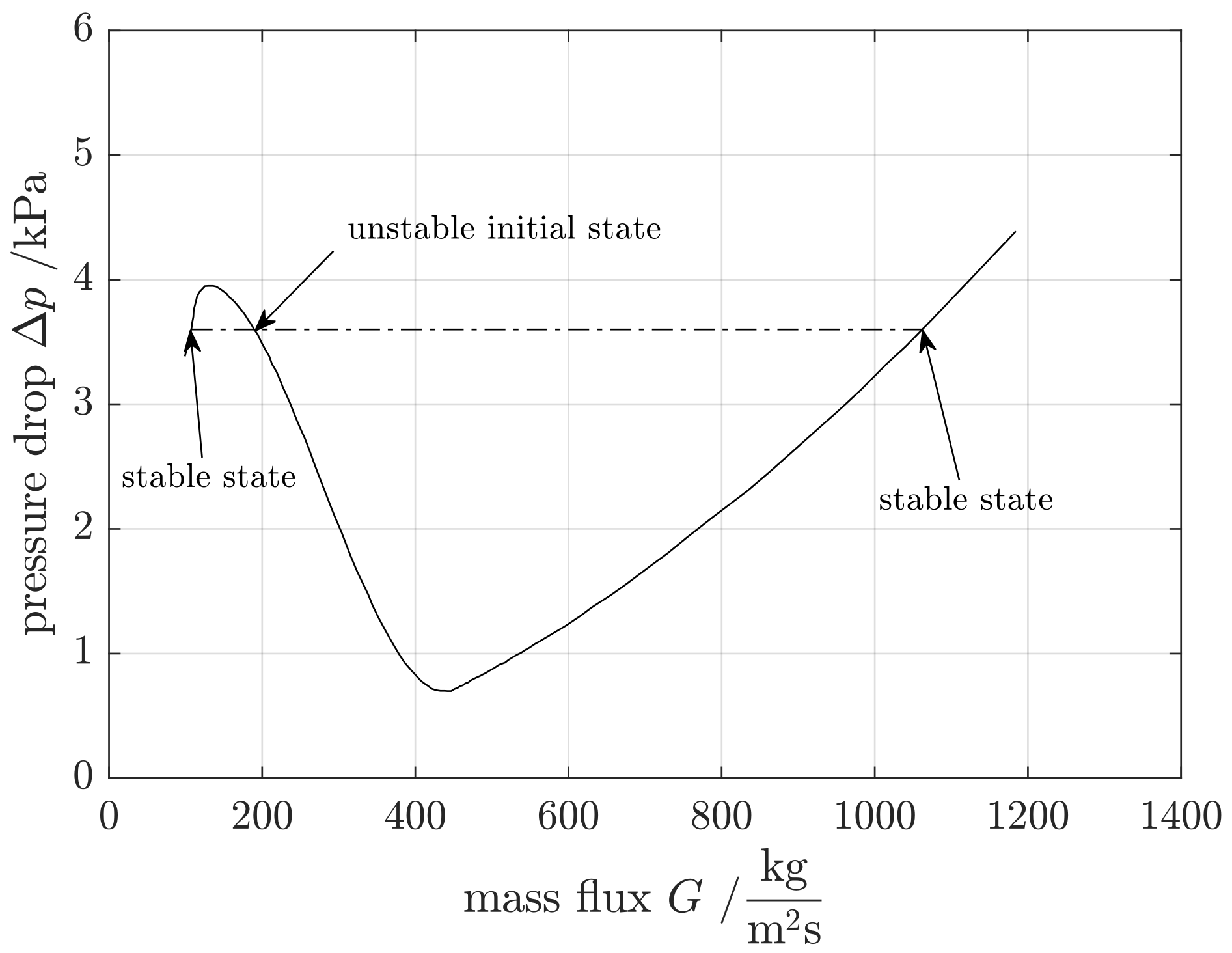
3.1.1. Ledinegg Instability

The Ledinegg instability is well known and intensively investigated. Ledinegg introduced this type at first in Ledinegg [75].
The flow excursions occur when the slope of the channel characteristic for boiling systems is more negative than the external characteristic at small perturbation around an equilibrium point [8]:
Δ p int G Δ p ext G .
Figure 10 shows the trend of the internal pressure drop in the cases of all vapor ( x = 1 ), all liquid ( x = 0 ) and mixture ( 0 < x < 1 ) in a cross-flow channel. Furthermore, two cases of external pressure drop trends induced by several pumps are shown. In case one, the characteristic curve of the pump has three intersections within the mixture characteristic curve.
The operating point B is unstable according to the stability criterion (cf. Equation (59)) and a small perturbation causes a change to the operating point A or C. If the new stable operating point A is reached, the system will be at the risk that the necessary cooling of the heated wall is not guaranteed and the critical heat flux is reached. This instability can be avoided by installing an inlet throttle valve, which leads to the characteristic curve of case two [8]. The stability criterion according to Equation (59) is now fulfilled and operating point B is stable. The external pressure drop of a natural circulation system is the buoyancy due to the gradient of the density. Whereas the internal pressure drop includes all losses in the inlet, boiling channel, exit and downcomer but the pressure drop due to gravity.
Detailed studies of the nonrecurring excursive instabilities with experimental background are published by Maulbetsch and Griffith [78], Bouré et al. [8] and Padki et al. [77]. Padki et al. discovered that the static Ledinegg instability is caused by a saddle-node bifurcation [77].
Nayak et al. [79] studied the stability behavior of the AHWR concept by prediction of the instability threshold in 1998. They concluded, inter alia, that the Ledinegg instability will disappear, if the system pressure is higher than 7 bar or the subcooling less than 10 K during start-up.
Rao et al. [80] carried out a linear stability analysis in a frequency domain in 1995. They figured out that the Ledinegg instability does not occur at the simultaneous presence of a neutronic and hydrodynamic feedback.
Ruspini et al. [81] investigated this phenomenon under low flow conditions by applying model order reduction (c.f. Figure 11). The solution of steady state results in the typical N-shape curve. If the slope is smaller than the external characteristic, the point will be unstable. Two simulations with different perturbation lead to a lower (in the case of an outlet pressure of 996.51 kPa) or higher (in the case of an outlet pressure of 996.49 kPa) mass flow rate.

3.1.2. The Boiling Crisis

The boiling crisis is caused by a non-wetted wall of a boiling channel and is characterized by an insignificant degradation of the heat transfer. At systems where the heat flux is fixed (e.g., nuclear reactors or electrical heating), the non-wetted wall leads to a steep increase of the wall temperature. This can even lead to the failure of heated surface (e.g., burn-out). If the heat is supplied by a given temperature gradient (e.g., steam heating), the heat flux will be strongly decreasing [82]. A review of the boiling crisis in nuclear reactors is given by Theofanous in 1980 Theofanous [83]. There are two existing types of the boiling crisis. The first type occurs by exceeding a certain CHF at a low vapor quality. The steam bubbles coalesce and form a steam film on the surface of a heated wall [84,85]. In case of a higher flow velocity and pressure, the small steam bubbles break away from the surface and form a high viscose bubble layer near the wall. This layer leads to the wetting of the heated wall. The second type of the boiling crisis occurs at the end of an annular flow (c.f. Figure 1). The liquid layer on the wall surface becomes very thin and disappears finally. This causes the degradation of the heat transfer because the heat is transferred to the steam.
Kim et al. [86] investigated the influence of the flow oscillation on the CHF under low power and low flow conditions in 1999. Nikolayev et al. [87] presented experimental investigations of the layer forming and concluded that their results are not compliant to the theoretical aspects of the Zuber model and the macrolayer evaporation theory.

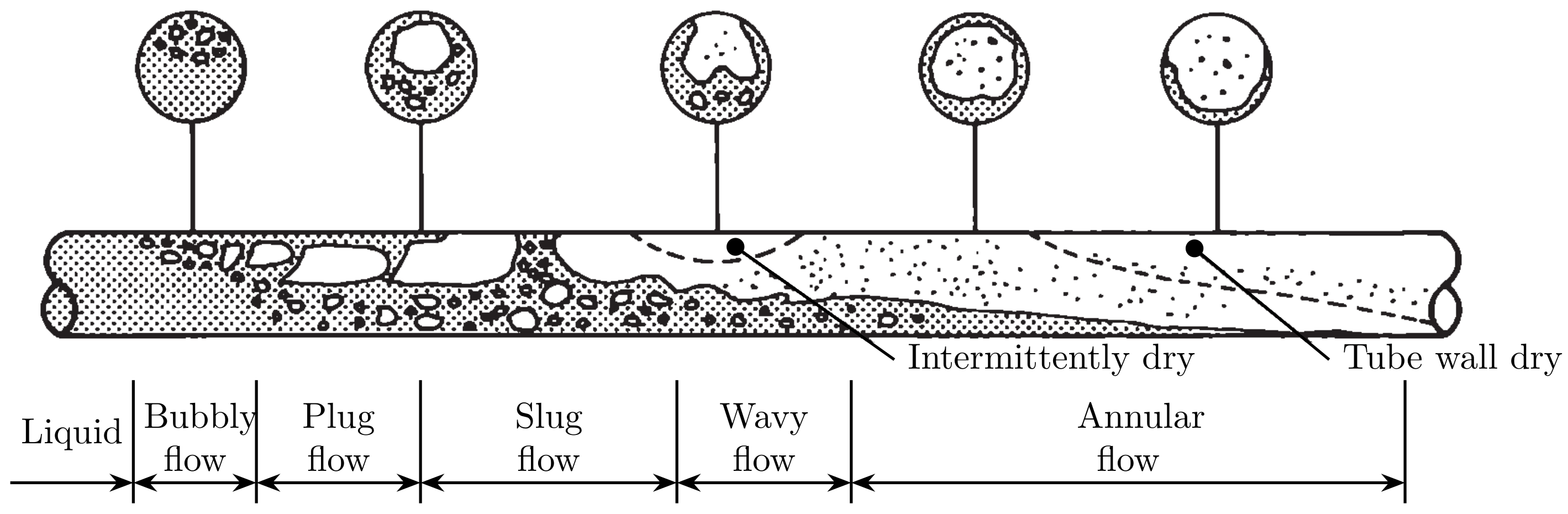
3.1.3. Flow Pattern Transition Instability
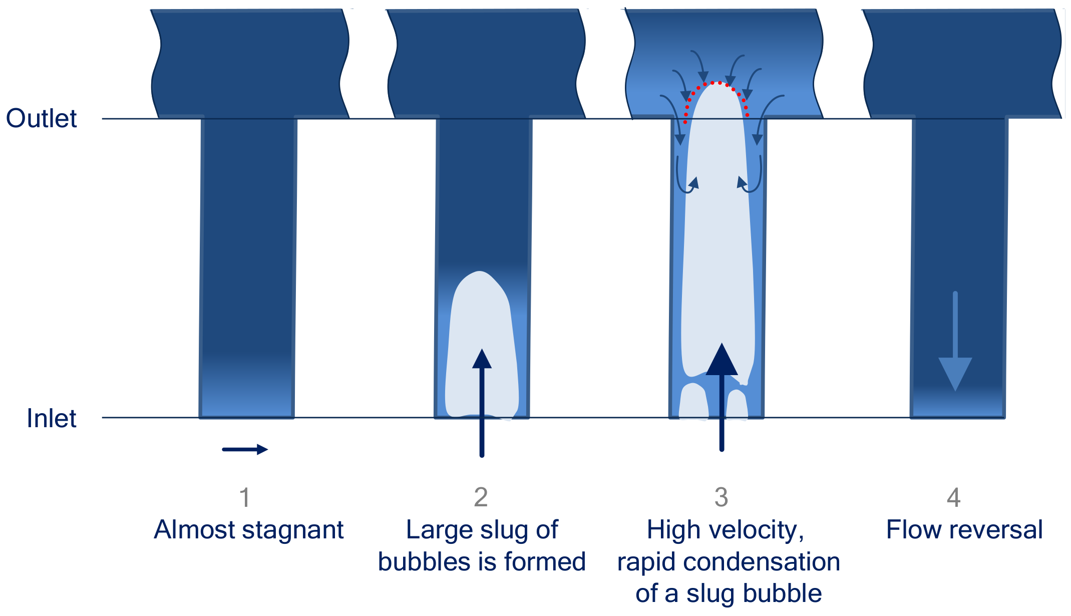
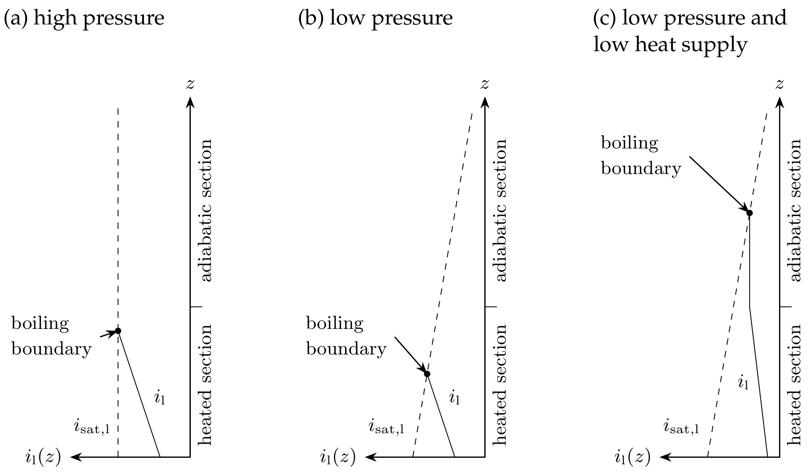
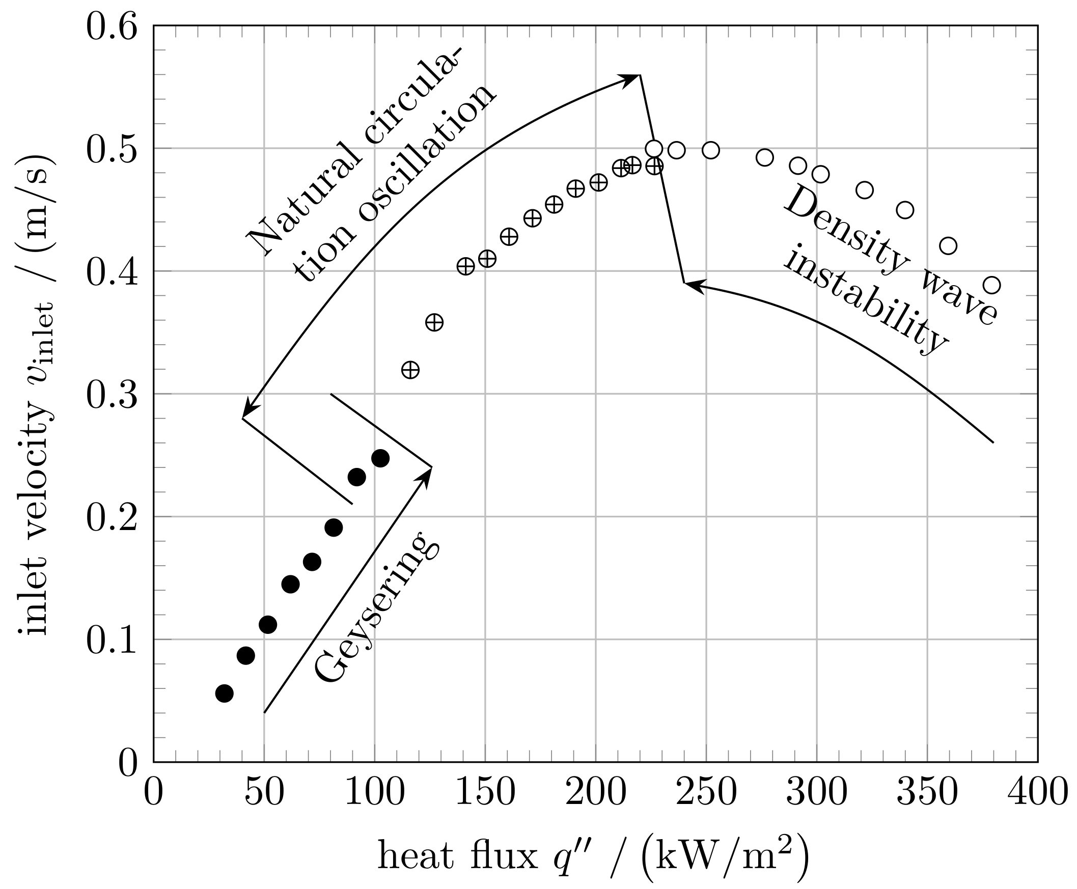
The flow pattern transition instability is classified as fundamental relaxation instability. As shown in Figure 1, there are various configurations of gas and liquid flow in a channel, in which these phases arrange themselves. These characteristic configurations are known as flow regimes. Instability occurs during the transition of bubbly to slug or annular flow. A small perturbation or reduction in the volumetric flow increases the quality, which changes the flow regime to the annular flow. The annular flow is characterized by a significantly lower pressure drop than the slug flow. Therefore, the flow rate increases and hence the quality decreases, these two effects lead to the happening of transition again [8].
The great challenge concerning the investigation of this type of instability is the prediction, when the slug flow is initiated. Griffith and Wallis [88] proposed an empirical flow regime map in 1961. Haberstroh and Griffith [89] figured out that the transition depends on the liquid flow rate and created an annular-slug transition criterion. Krussenberg et al. [90] investigated the two-phase flow concerning the transition to slug flow with a reasonable agreement to Taitel flow maps experimentally in 2000 (c.f. [91]). Krussenberg concluded that the slug flow occurs, when the bubble size distribution reaches higher values than the tube diameter. Further, analytical studies are presented by Nayak et al. [79] and Jeng and Pan [92].

3.1.4. Geysering

In general, the compound relaxation instabilities are non-periodical trends of flow dynamics and are irregular. The prediction of these instabilities bases on a steady state solution. General characteristics (e.g., amplitudes, frequencies) cannot be estimated analytically. The geysering instability is a classic example of a compound relaxation instability (c.f. [8]). By reaching the boiling boundary within the boiling channel, the increasing void fraction leads to a decreasing hydrostatic pressure along the channel. This results in an additional boiling above the detached steam bubble with an associated increasing mass flow. The steam bubble is condensing at the inlet of vessel filled with subcooled liquid and causes an eruption in the channel outlet.
Thereupon, the overlying subcooled liquid returns to the channel, which leads to the stagnation of the natural circulation flow [93]. This phenomenon was reported for the first time by Griffith [94]. He observed periods between 10 s and 100 s and finally concluded the occurrence of it at a low pressure and a low power.
Ozawa et al. [95] investigated this phenomenon experimentally on a forced circulation loop for the refrigerant R-113 in 1979. The three main processes of geysering reported by Griffith [94] (single-phase flow, ejection of vapor-liquid mixture and backflow) have also been observed. The period and the amplitude increase with an increasing heat flux and a decreasing inlet velocity. An increasing riser length also results in an increasing geysering-amplitude [95]. Aritomi et al. [96] also discovered in 1990, that the geysering period correlates with the boiling delay time, τ bd , which is the required time for the boiling of subcooled water, which flows through a boiling channel. The boiling delay time is defined as:
τ bd = ρ l i sat , l i l q ,
where ρ l is the liquid density, i sat , l the liquid saturation enthalpy, i l the inlet liquid enthalpy and q the volumetric heat generation rate.
In 2007, Marcel [97] observed only geysering instabilities in the test-facility CIRCUS with a parallel chimney configuration. At low pressure, the phenomenon was observed to be the most prevalent during the investigations on the open natural circulation test facility GENEVA by Cloppenborg et al. [98].
In Figure 12, two-phase-flow oscillations are shown, which are induced by geysering. If the large slug bubbles reach the riser outlet, the pressure drop in the riser will be reduced by the frictional pressure drop and the gravity of about 670 mbar. The gravity pressure drop results from the riser length of about 6 m. The time lag between the mass flow and the riser inlet temperature is nearly 18 s. During the reversal flow, the riser inlet temperature decreases to the subcooled temperature 90 C and increases during the first phase according to the geysering phenomenon (c.f. Figure 13).

3.2. Dynamic Instabilities

Dynamic instabilities were classified according to their causes for propagation of disturbance: density wave oscillations (DWO), pressure drop oscillations (PDO), thermal oscillations and acoustic oscillations. Table 2 represents the classification according to Bouré et al. [8]. Generally, there are two types of transportation of disturbances: pressure and void waves.

3.2.1. Acoustic Oscillation

Acoustic oscillations, also described as pressure wave oscillations, have been observed in the subcooled boiling, the bulk boiling and the film boiling. These oscillations appear at rather highly subcooled operating systems. A high frequency of about 10 Hz to 100 Hz was reported by several investigators [8]. The DWO produces lower frequency waves of about 1 Hz. Bishop et al. [100] detected audible frequency oscillations of 1000 Hz to 10,000 Hz during their experimental investigations in near-critical temperature and supercritical pressure operational conditions in 1964. The amplitudes are relatively small at such high frequencies. The thermal feedback of the vapor film to the passing pressure wave is assumed to be the mechanism for the oscillations during film boiling [12]. Detailed studies are published in [101,102,103].

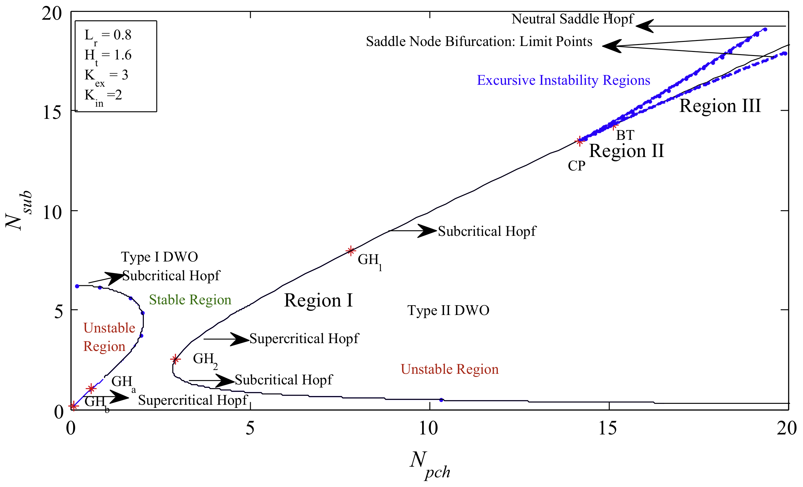
3.2.2. Density Wave Oscillation

The density wave oscillation is the most common type of flow instabilities. The mechanism is clearly understood and consists of two sub-mechanisms concerning the generation and propagation of the disturbance: the delay of the propagation and the feedback effects on the inlet conditions [104]. Fukuda and Kobori [105] classified these oscillations into two main types. The Type-I (DWOI) occurs at a very low exit quality, whereas a high quality at the exit is the characteristic feature of Type-II (DWOII). The pressure of the system is the key indicator for the dominant DWO type. Systems with a pressure below 20 bar (e.g., reactor start-up) are defined as low-pressure system and high pressure systems are specified with a higher pressure than 20 bar [106].
The saturation conditions in a low-pressure system strongly depend on the pressure level, which is shown in Figure 14b,c.
DWOI types are low frequency oscillations in a low pressure systems (c.f. Figure 14b) with a low exit quality. The gravity pressure drop of the adiabatic chimney dominates the system and is very sensitive to flow rate fluctuations. Therefore, the length of the riser plays an important role. With a small perturbation concerning the quality, the void fraction and finally the driving head undergoes a large change. An increasing heat supply suppresses the fluctuation of the driving head for small changes in the quality because of a decreasing slop of the void fraction versus quality [12].
The high frequency DWOII is important for a high pressure (c.f. Figure 14a) and a power, at which forced or natural circulation reactors operate. The oscillations are caused by the interaction of single and two-phase pressure drops, the mass flow and the void fraction in the two-phase region. A different propagation time delay in the single and two-phase region leads to pressure drop variations, which are out-of-phase.
Furthermore, the high-order DWOIII is analytically explained by Yadigaroglu and Bergles [107] and Yadigaroglu and Bergles [108]. During the experiments under atmospheric conditions, the DWOIII appears at a high subcooling and low power. In 1985, Achard et al. [109] applied the stability island to describe this phenomenon.
Fukuda and Kobori [105] subdivided these types into gravity or frictional effects of a heated section or riser (DWOI-R, DWOI-H, DWOII-R, DWOII-H) in 1979. Based on their experimental results in [110], these different types of instabilities are obtained by a linear stability analysis in a frequency domain and were observed at different configurations.
An important appearance, where density wave oscillations are induced, is flashing, which is also known as adiabatic boiling. The common flashing induced oscillations appear during a low-pressure operation, for example at the start-up of BWRs (c.f. Figure 14c). The steam is generated in the adiabatic riser because of the decreasing gravitational pressure drop and the saturation temperature along the riser. The steam generation causes an increase in the flow rate and a decrease in the hydrostatic head. The higher flow rate reduces the quality in the heated and riser section resulting in the upwards motion of the boiling boundary. The temperature in the channel becomes lower and the flow rate decreases, which leads to a higher dwell time in the heated section. The process starts again. Flashing is affected by the hydrostatic head and hence sometimes referred as DWOI. The phase difference of the temperature between the heated and the adiabatic section is similar and the dwell time of the fluid and the oscillation period is nearly the same [111]. This phenomenon was experimentally investigated by many researchers such as Schuster [112,113,114], Furuya et al. [5,115], Manera [116,117] and Cloppenborg [98,99].

3.2.3. Thermally Induced Oscillations

The thermally induced instabilities mostly appear in combination with DWO and are the result of the occurring critical heat flux. The high frequency DWO effects a disturbance in film boiling [8]. Due to the changes concerning the flow regimes (c.f. Figure 1) and finally in the heat transfer mechanism, the occurring critical heat flux is moving downward or upward the boiling channel. These instabilities are characterized by a large amplitude of the wall temperature oscillations subjected to a constant heat flux.

3.2.4. Parallel Channel Instabilities

The parallel channel instabilities can occur in single and two-phase systems, in which the channels are connected to a header. The pressure difference is same for all the channels. In and out of phase oscillations are observed, whereby out of phase oscillations play a dominant role. Kakac et al. [118] found a phase shift of 180 during experiments with two channels in 1974. In 1964, Berenson discovered a phase shift of 72 for five channels [119]. Summarizing the experimental results, the general statement of a phase shift with 2 π / n is formulated, where n is the number of channels [120].

3.2.5. Pressure Drop Oscillations

In general, pressure drop oscillations are caused by interactions between the channel and a compressible volume (e.g., surge tank or pressurizer) at the inlet of the heated channel and occur commonly at forced circulation system, because of the destabilization by the pump. Contrary to DWO, PDO occurs at higher flow rates and smaller frequencies. PDO is able to stand the same amount of the risks of occurring CHF as Ledinegg.

3.2.6. Natural Circulation Instabilities

According to Aritomi et al. [121], natural circulation oscillations occur during an increasing heat supply, when geysering is suppressed. This in-phase instability is induced by fluctuations of the hydrostatic head in an adiabatic long channel and disappears with a further increasing heat supply and vaporization rate.

3.3. Experiments

The experimental investigations provide the basis for the evaluation of the analytical investigations with respect to the modeling. The following section gives a brief overview of the experimental investigations of natural circulation loops concerning two-phase flow instabilities.
Wallis and Heasley [6], the most cited publication, investigated the oscillatory behavior in a natural circulation loop experimentally (cf. Figure 15) and numerically. They discovered DWOI and DWOII during their natural circulation loop operated with pentane.
Dijkman et al. [122] investigated the stability of a water operated natural and forced circulation system in 1967. The transfer functions have been measured for the investigation of the stability at steady state conditions. The heated section is electrically heated. The system pressure was varied between 2, 14.7 and 30.4 bar and the power supply was adjusted up to the burnout. The estimated low frequencies of about 0.9 Hz suggest the occurrence of DWOII.
A vast parameter analysis was published by Mathisen [123], who varied the system pressure, inlet and outlet restriction of a single and parallel boiling channel. Mathisen concluded, that the increase of the system pressure, the initial inlet restriction in the separate channels and the ratio of the effective head to the riser length have definitely stabilizing effect regarding the onset of Ledinegg phenomenon. The best performance was observed at minimum subcooling and minimum main flow restriction with parallel boiling channels.
The classification of DWO according to Fukuda and Kobori [105] is based on their experimental investigations. The results were published in [110]. They observed DWOI, where the gravitational factor is the governing factor, and DWOII, where the frictional pressure drop is dominant. It was also shown that the PDO is included in the DWOI.
Schuster investigated the transient behavior of a two-phase natural circulation, which occurs in the test facility DANTON. This test facility represented the axial main dimension of the soviet nuclear district heating station AST-500 in scale 1:1. The start-up was performed in 1985 with respect to the investigation of the thermal hydraulic behavior [113].
In 2000, Schuster et al. [124] stated that the passing through an unstable two-phase region to reach a stable two-phase flow is unavoidable without external pressurizing. During the start-up three types of instabilities are observed: flashing, geysering and DWOII. The main results generally agreed with [96,125]. The study of the start-up procedure was not relevant for the future because the AST-500 is not pursued anymore. But the detailed study of the flashing phenomenon published in [112,113,114] was not yet been done before. The observed flashing at a low pressure near ambient conditions and a low heat flux density induced oscillations with frequencies lower than 0.5 Hz.
Figure 16 shows results of the simplified model, which bases on the steady-state equations of energy, momentum and mass. This dependence agrees with the experimental results qualitatively. The riser inlet subcooling has a greater influence on the flashing onset than the riser inlet temperature.
It was shown that this phenomenon has been taken into account for a sufficient start-up procedure and an effective reactor configuration in natural circulation BWR. A detailed discussion of a natural circulation BWR is introduced, inter alia, by Aritomi et al. [96,121]. The experimental investigation of a natural circulation boiling process is carried out in a single vertical boiling channel [96] and parallel boiling channels [121] under the atmospheric pressure. Based on the low-pressure natural circulation experiments in [121] at a heat flux density up to 800 kW / m 2 in a 1 m long heated section, Aritomi et al. estimated three types of two-phase flow instabilities. With an increasing heat flux density, the natural circulation rate is increasing and the geysering is initiated. When the inlet velocity enhances due to an increasing heat flux, the geysering is superseded by a so-called natural circulation oscillation induced by the hydrostatic head fluctuation (cf. Figure 17). The density wave oscillations are following them.
At a high subcooling ( N sub = 156 ) and a low power ( N pch = 16 ), a chaotic behavior of the low pressure natural circulation loop was detected by Wu et al. [126]. This results are nearly compliant with [124].
A further natural circulation nuclear reactor is developed by the Institute of Nuclear Energy and Technology (INET) and is in operation since 1989. This 5 MW nuclear heating reactor (NHR-5) operates at system pressure of 15 bar. Jiang et al. [127] investigated the start-up at HRTL-5, which represented the geometric and the system design of NHR-5, experimentally in 1995. They observed geysering, flashing (at a pressure lower than 3 bar) and DWOI during the start-up and proposed a stable start-up procedure. The intense research on the physics of the static and dynamic behavior of the natural circulation operating Dodewaard reactor is published by [106,128,129,130]. Table 3 shows a brief overview of the experimental investigations in the test facilities with respect to the two-phase flow instabilities in BWR’s.
Large integral test facilities such as INKA, PANDA, PUMA and KATHY were established to observe various feedback effects and boundary conditions, which are realistic in BWRs.
The results of the experimental investigations contain the following main statements to stabilized the two-phase flow in general, which are also summarized by [78]:
  • Increasing the single-phase flow pressure drop in the heated section
  • Increasing the system pressure
  • Decreasing the inlet subcooling

3.4. Numerical Investigations

The boiling of a fluid flow within a channel is characterized by a two-phase flow and the resulting disequilibrium. The various spatial and time-dependent distributions of the state variables in the vapor and liquid effects stochastic interactions at the phase boundary interfaces. The analytic formulations of the complete complex system require a spatial averaging as a simplification due to their large computational effort. With averaging the state variables for an one-dimensional flow in general, three conservation equations (mass, momentum and energy) for each phase exist. The complexity increases at the transition from a mixture to multi component model. Mixture models are developed for describing a two-phase flow (liquid and vapor) within a defined validation range and assumptions as a pseudo-single phase fluid.
The first most famous cited lucid treatment of the natural circulation instabilities was presented by Wallis and Heasley [6]. They studied the effect of the inlet throttling of the two-phase flow instabilities and concluded that the increasing single-phase pressure drop stabilized the system. A linear stability analysis using a homogenous equilibrium model based on a lumped parameter system was carried out by Zuber [139]. He has given the first introduction of the drift velocities and finally the first approach of the drift-flux mixture model. For example, he discovered that the gravity terms in the single-phase heated section are damping, whereas the gravity terms in the two-phase section are driving terms [125].
Beside the classic method of linear frequency-domain stability analysis, which has been used to study density wave oscillations in [7], the nonlinear stability analysis has attracted considerable interest since 1990s. The nonlinear analysis was used at first by Achard et al. [109], Uddin and Dorning [140] and Clausse and Lahey [141]. The nonlinear effects of two-phase flow dynamics have also been investigated by Pinheiro Rosa and Podowski [142]. The observed results strongly depend on the numerical approaches and the applied spatial discretization, especially for the operating conditions in the linear unstable regions. Pinheiro et al. compared the effects of perturbation on various two-phase flow approaches: the homogenous equilibrium model and two different models of subcooled boiling, which seems to be a significant stable criterion. Furthermore, the results show, that the HEM agrees well with the experimental data at a low subcooling number and phase change number, whereas the drift flux model approximates more exactly at a higher subcooling number and phase change number [142]. Dokhane [143] concluded that the influence of subcooled boiling on the dynamic behavior is sensitive at a low subcooling.
Table 4 represents a brief overview of numerical investigations of two-phase flow instabilities in boiling channels or of a whole BWR system. The nonlinear effect was investigated in detail by application of various techniques of model order reduction, especially with the respect to the bifurcation theory. This theory is explained in detail by Hassard et al. [144]. The advanced BWR-ROM of Lange et al. [145] and the application of the nonlinear stability analysis shows a good agreement with the oscillatory behavior of several operating points of the Swiss nuclear power plant in Leibstadt. But the application of the weighted residual method of DFM based on a two-phase model requires a high computational effort. In contrast, the proper orthogonal decomposition (cf. Prill [146]) offers the opportunity to obtain the ROM based on a set of data time series and provides the best approximation.
In 2017, Pandey and Singh [159] published the results of the nonlinear stability analysis of a high pressure natural circulation loop based on previous verified and developed ROM by Paul and Singh [157]. The formulated two-phase region is based on the drift-flux mixture model. The approaches are comparable with those of [150], whereupon they use a linear approximation for the single phase density. Super- and subcritical bifurcation were detected at certain design parameters, especially when DWOI and DWOII stability boundaries diverged from each other [157].
In Figure 18, the DWO are represented by a Hopf bifurcation and the Ledinegg instabilities are characterized by a saddle-node bifurcation [159]. At low-pressure conditions, the pressure dependency of the saturation condition is pronounced (cf. Figure 14b). Zhou introduced a linear approximation of the saturation enthalpy as function of the pressure in the single-phase region [154]. But his two-phase region considered a homogeneous mixture model. This aspect and the high sensitivity of the saturation condition are the keynotes for a realistic formulation of a ROM and finally the application of nonlinear stability analysis.

4. Conclusions

The KERENATM concept pursues the strategy to simplify the systems, to achieve a higher reliability and a higher safety standard by the application of passive safety system for shutdown and decay heat removal. The simulation of these systems by integral codes, however, shows potential for further development, since the current empirical correlations for the heat transfer at the occurring low mass flows are not reliable. The purpose of this paper (part I and part II) is to summarize and discuss these existing empirical correlations to the relevant thermal hydraulic processes in the emergency condenser (EC) and the containment cooling condenser (CCC). These relevant thermal hydraulic processes can be categorized as: steam condensation inside incline tubes (EC), steam condensation on inclined tubes (CCC), boiling on inclined tubes (EC), boiling inside inclined tubes (CCC) and the natural circulation as a driving force. The first part covers the first three topics [1]. This article is the continuation of the first part with a focus on the boiling process inside inclined tubes and the two-phase instabilities in natural circulation systems. The correlations of the heat transfer implemented in the one-dimensional integral codes ATHLET, RELAP and TRACE are introduced and discussed. Several experimental investigations and the used test facilities are described and summarized, which have formed the base for the formulation of the heat transfer correlation in this special case of low mass flux. In addition, an overview is given to already performed simulations using CFD. Furthermore the scientific work on analytical and experimental investigations of the two-phase instabilities is summarized.

Author Contributions

Project Administration, C.S. and A.H.; Supervision, D.L., C.S., S.L., A.H. and U.H.; Visualization, R.M.; Writing—original draft, R.M., F.V., A.M.S., Y.Z. and W.D.; Writing—Review & Editing, R.M. and U.H. All authors have read and agreed to the published version of the manuscript.

Funding

This research was funded by Bundesministerium für Bildung und Forschung grant number 02NUK041. The APC was funded by Sächsische Landesbibliothek—Staats- und Universitätsbibliothek Dresden.

Acknowledgments

This work is part of the research project PANAS and is sponsored by the German Federal Ministry of Education and Research (BMBF) under the contract number 02NUK041. Responsibility for the content of this publication lies with the authors. Open Access Funding by the Publication Fund of the TU Dresden.

Conflicts of Interest

The authors declare no conflict of interest. The funders had no role in the design of the study; in the collection, analyses, or interpretation of data; in the writing of the manuscript, or in the decision to publish the results.

Abbreviations

AHWRAdvanced heavy water reactor
AST-500Soviet small nuclear reactor for district heating station, 500 MW thermal power
ATHLETAnalysis of thermal-hydraulics of leaks and transients
BWRBoiling water reactor
CFDComputational fluid dynamic
CHFCritical heat flux
CIRCUSCirculation during start-up, Delft University of Technology, Netherlands
DANTONDresdner Anlage für Naturumlauf mit teilweiser originaler Nachbildung, Technische Universität Dresden, Germany
DESIREDelft simulated reactor, Delft University of Technology, Netherlands
DFMDrift-flux mixture
DWODensity wave oscillation
GENEVAGenerische Einschleifen-Naturumlauf-Versuchsanlage, Technische Universität Dresden, Germany
GFGhost fluid
GRSGesellschaft für Anlagen und Reaktorsicherheit
HEMHomogeneous equilibrium mixture model
HRTL-5Heating reactor test loop with a thermal power of about 5 MW, Tsinghua University, Beijing, China
INKAIntgral Teststand Karlstein, AREVA, Karlstein, Germany
KATHYKarlstein thermal hydraulic test loop, AREVA, Karlstein, Germany
LBLattice Boltzmann
LOCAloss of coolant accidents
NHR-55 MW nuclear heating reactor, Institute of Nuclear Energy and Technology, Tsinghua University, Beijing, China
PANDALarge scale, thermal-hydraulics test facility, Paul Scherrer Institute (PSI), Villigen, Switzerland
PCIParallel channel instabilities
PCLParallel channel loop, Bhabha atomic research centre, Trombay, Mumbai, India
PDOPressure drop oscillation
PUMAPurdue university multi-dimensional integral test assembly, USA
PWRPressure water reactor
RELAPReactor excursion and leak analysis program
ROMReduced order model
SBLOCASmall break loss of coolant accidents
SBWRSimplified boiling water reactor
SIRIUS-NSimulated reactivity feedback implemented into thermal-hydraulic stability for natural circulation BWR
TRACETRAC/RELAP Advanced computational engine
VoFVolume-of-fluid
VOSETVolume of fluid level set
Nomenclature
A 1 F Wall fraction cooled by single-phase convection
A 2 F Wall fraction cooled by quenching
cRelaxation factor
c p Isobar specific heat capacity [J/(kgK)]
dDroplet diameter [m]
DHydraulic diameter [m]
fFanning friction factor
FReynolds number factor
F o Fourier number
gGravitational constant [ 9.81 m / s 2 ]
GMass flux [ kg / ( m 2 s ) ]
G r Grashof number
hHeat transfer coefficient [ W / ( m 2 K ) ]
iEnthalpy [kJ/kg]
J a Jacob number
KConstant
LLength [m]
l s Capillary length [m]
MVertical stratification and mixture level tracking models multiplier
m ˙ Mass flow [kg/s]
M α Void fraction factor
NExponent
n ˜ Normal vector to the surface
N pch Phase change number
N sub Subcooling number
N u Nusselt number
pPressure [Pa]
P r Prandtl number
q Heat flow [W]
q Heat flux [ kW / m 2 ]
q Volumetric heat generation rate [ kW / m 3 ]
RRadiation terms
R e Reynolds number
SBoiling suppression factor
TTemperature [K]
uAveraged flow velocity at phase boundary [m/s]
xSteam mass quality
YConstant
Δ i lv Latent heat of evaporation [kJ/kg]
Greek
α Volume fraction
γ Inclination angle /grad
δ Vapor film thickness
δ * Non-dimensional vapor film thickness
ε One dimensional delta function of normal coordinate n
λ Thermal conductivity [W/(mK)]
μ Dynamic viscosity [kg/(ms)]
ρ Density [ kg / m 3 ]
σ Surface tension [N/m]
τ bd Boiling delay time [s]
ϵ Emissivity
Indices
bBubble
CHFCritical heat flux
EEvaporation
extExternal
FConvection
intInternal
lLiquid
macMacroscopic
micMicroscopic
QQuenching
relRelative
satSaturation
tarTarget
totTotal
TPTwo-phase
vVapor
wWall

References

  1. Moonesi, A.S.; Zhang, Y.; Viereckl, F.; Manthey, R. Modelling of passive heat removal systems: A review with reference to the Framatome BWR reactor KERENA: Part I. Energies 2019, 13, 35. [Google Scholar] [CrossRef] [Green Version]
  2. Moonesi, A.S.; Bieberle, A.; Von der Cron, D.; Ding, W.; Krepper, E.; Lucas, D.; Hampel, U. Flow morphology and heat transfer analysis in an inclined condensation pipe part II: Numerical investigations. Nuclear Eng. Des. 2020. not yet published. [Google Scholar]
  3. Cheng, L.; Ribatski, G.; Thome, J.R. Two-Phase Flow Patterns and Flow-Pattern Maps: Fundamentals and Applications. Appl. Mech. Rev. 2008, 61, 050802. [Google Scholar] [CrossRef]
  4. Auban, O.; Paladino, D.; Zboray, R. Experimental investigation of natural-circulation flow behavior under low-power/low-pressure conditions in the large-scale PANDA facility. Nucl. Technol. 2004, 148, 294–312. [Google Scholar] [CrossRef]
  5. Furuya, M.; Inada, F.; van der Hagen, T. Flashing-induced density wave oscillations in a natural circulation BWR—Mechanism of instability and stability map. Nucl. Eng. Des. 2005, 235, 1557–1569. [Google Scholar] [CrossRef]
  6. Wallis, G.B.; Heasley, J.H. Oscillations in Two-Phase Flow Systems. J. Heat Transf. 1961, 83, 363. [Google Scholar] [CrossRef]
  7. Ishii, M. Thermally Induced Flow Instabilities in Two-Phase Mixtures in Thermal Equilibrium. Ph.D. Thesis, Georgia Institute of Technology, Atlanta, GA, USA, 1971. [Google Scholar]
  8. Bouré, J.A.; Bergles, A.E.; Tong, L.S. Review of two-phase flow instability. Nucl. Eng. Des. 1973, 25, 165–192. [Google Scholar] [CrossRef]
  9. Kakaç, S.; Veziroglu, T.N. A Review of Two-Phase Flow Instabilities. In Advances in Two-Phase Flow and Heat Transfer; Kakaç, S., Ishii, M., Eds.; Springer Netherlands: Dordrecht, The Netherlands, 1983; pp. 577–667. [Google Scholar] [CrossRef]
  10. Prasad, G.V.D.; Pandey, M.; Kalra, M.S. Review of research on flow instabilities in natural circulation boiling systems. Prog. Nucl. Energy 2007, 49, 429–451. [Google Scholar] [CrossRef]
  11. Kakac, S.; Bon, B. A Review of two-phase flow dynamic instabilities in tube boiling systems. Int. J. Heat Mass Transf. 2008, 51, 399–433. [Google Scholar] [CrossRef]
  12. Nayak, A.K.; Vijayan, P.K. Flow Instabilities in Boiling Two-Phase Natural Circulation Systems: A Review. Sci. Technol. Nucl. Install. 2008, 2008, 1–15. [Google Scholar] [CrossRef] [Green Version]
  13. Bhattacharyya, S.; Basu, D.N.; Das, P.K. Two-Phase Natural Circulation Loops: A Review of the Recent Advances. Heat Transf. Eng. 2012, 33, 461–482. [Google Scholar] [CrossRef]
  14. Ruspini, L.C.; Marcel, C.P.; Clausse, A. Two-phase flow instabilities: A review. Int. J. Heat Mass Transf. 2014, 71, 521–548. [Google Scholar] [CrossRef]
  15. Verein Deutscher Ingenieure. VDI-Wärmeatlas, 10th ed.; VDI Buch, Springer: Berlin, Germany, 2006. [Google Scholar]
  16. Collier, J.G.; Thome, J.R. Convective Boiling and Condensation, 3rd ed.; reprint 2001 ed.; The Oxford Engineering Science Series; Clarendon Press: Oxford, UK; Oxford University Press: New York, NY, USA, 2001; p. 38. [Google Scholar]
  17. Lerchl, G.; Austregesilo, H.; Schöffel, P.; Von der Cron, D.; Weyermann, F. ATHLET 3.1A: User’s Manual, 1st ed.; GRS gmbH: Garching, Germany, 2016. [Google Scholar]
  18. Chen, J.C. Correlation for Boiling Heat Transfer to Saturated Fluids in Convective Flow. Ind. Eng. Chem. Process Des. Dev. 1966, 5, 322–329. [Google Scholar] [CrossRef] [Green Version]
  19. Liesch, K.J.; Raemhild, G.; Hofmann, K. Zur Bestimmung des Wärmeübergangs und der kritischen Heizflächenbelastung im Hinblick auf besondere Verhältnisse in den Kühlkanälen eines DWR bei schweren Kühlmittelverluststörfällen; MRR-15: TU-München, Germany, 1975. [Google Scholar]
  20. Gröber, H.; Erk, S.; Grigull, U. Die Grundgesetze der Wärmeübertragung; Springer: Berlin/Heidelberg, Germany, 1963. [Google Scholar] [CrossRef]
  21. Vojtek, I. Auswertung der 25-Stabbündel-Versuche mit dem Rechenprogramm BRUDI-VA; GRS-A-208; GRS: Gaithersburg, MD, USA, 1978.
  22. Berenson, P.J. Film-Boiling Heat Transfer From a Horizontal Surface. J. Heat Transf. 1961, 83, 351–356. [Google Scholar] [CrossRef]
  23. Bromley, L.A.; LeRoy, N.R.; Robbers, J.A. Heat Transfer in Forced Convection Film Boiling. Ind. Eng. Chem. 1953, 45, 2639–2646. [Google Scholar] [CrossRef]
  24. The RELAP5-3D© Code Development Team. RELAP5-3D© Code Manual Volume IV: Models and Correlations; Idaho National Laboratory: Idaho Falls, IE, USA, 2012.
  25. Bjornard, T.A.; Griffith, P. PWR Blowdown Heat Transfer. In Winter Annual Meeting; Thermal and Hydraulic Aspects of Nuclear Reactor Safety; American Society of Mechanical Engineers: Atlanta, GA, USA, 1977; Volume I, Light Water Reactors. [Google Scholar]
  26. Sudo, Y.; Murao, Y. Film Boiling Heat Transfer during Reflood Process; Japan Atomic Energy Research Inst.: Tokyo, Japan, 1976. [Google Scholar]
  27. Sun, K.H.; Gonzales-Santalo, J.M.; Tien, C.L. Calculations of Combined Radiation and Convection Heat Transfer in Rod Bundles Under Emergency Cooling Conditions. Trans. ASME J. Heat Transf. 1976, 98, 414–420. [Google Scholar] [CrossRef]
  28. Sparrow, E.M.; Cess, R.D. Radiation Heat Transfer; Brooks/Cole Pub. Co: Belmont, CA, USA, 1970. [Google Scholar]
  29. NRC, U.S. TRACE V5.0 p2: Theory Manual; Office of Nuclear Regulatory Research; U.S. Nuclear Regulatory Commission: Washington, DC, USA, 2010.
  30. Steiner, D.; Taborek, J. Flow Boiling Heat Transfer in Vertical Tubes Correlated by an Asymptotic Model. Heat Transf. Eng. 1992, 13, 43–69. [Google Scholar] [CrossRef]
  31. Cooper, M.G. Heat Flow Rates in Saturated Nucleate Pool Boiling-A Wide-Ranging Examination Using Reduced Properties. Adv. Heat Transf. 1984, 16, 157–239. [Google Scholar] [CrossRef]
  32. Gorenflo, D. (Ed.) Pool Boiling, VDI-Heat Atlas; Oxford University Press: Oxford, UK, 1994. [Google Scholar]
  33. Holman, J.P. Heat Transfer; McGraw-Hill: New York, NY, USA, 1997. [Google Scholar]
  34. Lee, R.C.; Nydahl, J.E. Numerical Calculation of Bubble Growth in Nucleate Boiling From Inception Through Departure. J. Heat Transf. 1989, 111, 474. [Google Scholar] [CrossRef]
  35. Son, G.; Dhir, V.K.; Ramanujapu, N. Dynamics and Heat Transfer Associated With a Single Bubble During Nucleate Boiling on a Horizontal Surface. J. Heat Transf. 1999, 121, 623–631. [Google Scholar] [CrossRef]
  36. Tryggvason, G.; Lu, J. Direct Numerical Simulations of Flows with Phase Change. Procedia IUTAM 2015, 15, 2–13. [Google Scholar] [CrossRef] [Green Version]
  37. Sato, Y.; Ničeno, B. A sharp-interface phase change model for a mass-conservative interface tracking method. J. Comput. Phys. 2013, 249, 127–161. [Google Scholar] [CrossRef]
  38. Sato, Y.; Niceno, B. A depletable micro-layer model for nucleate pool boiling. J. Comput. Phys. 2015, 300, 20–52. [Google Scholar] [CrossRef]
  39. Duan, X.; Phillips, B.; McKrell, T.; Buongiorno, J. Synchronized High-Speed Video, Infrared Thermometry, and Particle Image Velocimetry Data for Validation of Interface-Tracking Simulations of Nucleate Boiling Phenomena. Exp. Heat Transf. 2013, 26, 169–197. [Google Scholar] [CrossRef]
  40. Yabuki, T.; Nakabeppu, O. Heat transfer mechanisms in isolated bubble boiling of water observed with MEMS sensor. Int. J. Heat Mass Transf. 2014, 76, 286–297. [Google Scholar] [CrossRef]
  41. Sato, Y.; Niceno, B. Pool boiling simulation using an interface tracking method: From nucleate boiling to film boiling regime through critical heat flux. Int. J. Heat Mass Transf. 2018, 125, 876–890. [Google Scholar] [CrossRef]
  42. Drew, D.A.; Passman, S.L. Theory of Multicomponent Fluids; Applied Mathematical Sciences; Springer: New York, NY, USA, 1999; Volume 135. [Google Scholar]
  43. Ishii, M. Thermo-Fluid Dynamic Theory of Two-Phase Flow; Eyrolles: Paris, France, 1975. [Google Scholar]
  44. Yeoh, G.H.; Tu, J. Modelling Subcooled Boiling Flows; Nova Science Publ: New York, NY, USA, 2009. [Google Scholar]
  45. Judd, R.L.; Hwang, K.S. A Comprehensive Model for Nucleate Pool Boiling Heat Transfer Including Microlayer Evaporation. J. Heat Transf. 1976, 98, 623. [Google Scholar] [CrossRef]
  46. Kurul, N.; Podowski, M.Z. Multidimensional effects in forced convection subcooled boiling. In Proceeding of the 9th International Heat Transfer Conference; Begellhouse: Redding, CT, USA, 1990; pp. 21–26. [Google Scholar] [CrossRef]
  47. Kurul, N.; Podowski, M.Z. On the modeling of multidimensional effects in boiling channels. In Proceeding of the 27th National Heat Transfer Conference; American Institute of Aeronautics and Astronautics: Reston, VA, USA, 1991. [Google Scholar]
  48. Tolubinsky, V.I.; Kostanchuk, D.M. Vapour bubbles growth rate and heat transfer intensity at subcooled water boiling. In Proceedings of the 4th International Heat Transfer Conference; Begellhouse: Redding, CT, USA, 1970; pp. 1–11. [Google Scholar] [CrossRef]
  49. Kocamustafaogullari, G. Pressure dependence of bubble departure diameter for water. Int. Commun. Heat Mass Transf. 1983, 10, 501–509. [Google Scholar] [CrossRef]
  50. Ünal, H.C. Maximum bubble diameter, maximum bubble-growth time and bubble-growth rate during the subcooled nucleate flow boiling of water up to 17.7 MN/m2. Int. J. Heat Mass Transf. 1976, 19, 643–649. [Google Scholar] [CrossRef]
  51. Klausner, J.F.; Mei, R.; Bernhard, D.M.; Zeng, L.Z. Vapor bubble departure in forced convection boiling. Int. J. Heat Mass Transf. 1993, 36, 651–662. [Google Scholar] [CrossRef]
  52. Zeng, L.Z.; Klausner, J.F.; Mei, R. A unified model for the prediction of bubble detachment diameters in boiling systems—I. Pool boiling. Int. J. Heat Mass Transf. 1993, 36, 2261–2270. [Google Scholar] [CrossRef]
  53. Zeng, L.Z.; Klausner, J.F.; Bernhard, D.M.; Mei, R. A unified model for the prediction of bubble detachment diameters in boiling systems—II. Flow boiling. Int. J. Heat Mass Transf. 1993, 36, 2271–2279. [Google Scholar] [CrossRef]
  54. Krepper, E.; Rzehak, R. CFD for subcooled flow boiling: Simulation of DEBORA experiments. Nucl. Eng. Des. 2011, 241, 3851–3866. [Google Scholar] [CrossRef]
  55. Colombo, M.; Fairweather, M. Prediction of bubble departure in forced convection boiling: A mechanistic model. Int. J. Heat Mass Transf. 2015, 85, 135–146. [Google Scholar] [CrossRef]
  56. Ding, W.; Krepper, E.; Hampel, U. Evaluation of the microlayer contribution to bubble growth in horizontal pool boiling with a mechanistic model that considers dynamic contact angle and base expansion. Int. J. Heat Fluid Flow 2018, 72, 274–287. [Google Scholar] [CrossRef]
  57. Ding, W.; Krepper, E.; Hampel, U. The Implementation of an Activated Temperature-Dependent Wall Boiling Model in an Eulerian-Eulerian Computational Fluid Dynamics Approach for Predicting the Wall Boiling Process. Nucl. Technol. 2018, 205, 23–32. [Google Scholar] [CrossRef]
  58. Krepper, E.; Ding, W. Review of Subcooled Boiling Flow Models. In Handbook of Multiphase Flow Science and Technology; Yeoh, G.H., Ed.; Springer Singapore: Singapore, 2017. [Google Scholar]
  59. Lifante, C.; Frank, T.; Burns, A. Wall boiling modeling extension towards critical heat flux. In Proceedings of the 15th International Topical Meeting on Nuclear Reactor Thermalhydraulics, Pisa, Italy, 12–17 May 2013. [Google Scholar]
  60. Bartolomej, G.G. An experimental investigation of true volumetric vapour content with subcooled boiling in tubes. Therm. Eng. 1982, 29, 132–135. [Google Scholar]
  61. Hoyer, N. Calculation of dryout and post-dryout heat transfer for tube geometry. Int. J. Multiph. Flow 1998, 24, 319–334. [Google Scholar] [CrossRef]
  62. Bruder, M.; Sattelmayer, T. An Empirical Correlation for the Void Fraction at Critical Heat Flux Close to the Wall for Subcooled Flow Boiling of a Low Boiling Refrigerant. Heat Mass Transf. Res. J. 2018, 2, 14–28. [Google Scholar]
  63. Ding, W.; Geißler, T.; Krepper, E.; Hampel, U. Critical heat flux as a mass flux dependent local or global phenomenon: Theoretical analysis and experimental confirmation. Int. J. Therm. Sci. 2018, 130, 200–207. [Google Scholar] [CrossRef]
  64. Krepper, E.; Lucas, D.; Prasser, H.M. On the modelling of bubbly flow in vertical pipes. Nucl. Eng. Des. 2005, 235, 597–611. [Google Scholar] [CrossRef]
  65. Krepper, E.; Rzehak, R.; Lifante, C.; Frank, T. CFD for subcooled flow boiling: Coupling wall boiling and population balance models. Nucl. Eng. Des. 2013, 255, 330–346. [Google Scholar] [CrossRef]
  66. Hänsch, S.; Lucas, D.; Krepper, E.; Höhne, T. A multi-field two-fluid concept for transitions between different scales of interfacial structures. Int. J. Multiph. Flow 2012, 47, 171–182. [Google Scholar] [CrossRef]
  67. Höhne, T.; Krepper, E.; Montoya, G.; Lucas, D. CFD-simulation of boiling in a heated pipe including flow pattern transitions using the GENTOP concept. Nucl. Eng. Des. 2017, 322, 165–176. [Google Scholar] [CrossRef]
  68. Gupta, A.; Saini, J.S.; Varma, H.K. Boiling heat transfer in small horizontal tube bundles at low cross-flow velocities. Int. J. Heat Mass Transf. 1995, 38, 599–605. [Google Scholar] [CrossRef]
  69. Yu, W.; France, D.M.; Wambsganss, M.W.; Hull, J.R. Two-phase pressure drop, boiling heat transfer, and critical heat flux to water in a small-diameter horizontal tube. Int. J. Multiph. Flow 2002, 28, 927–941. [Google Scholar] [CrossRef]
  70. Wojtan, L.; Ursenbacher, T.; Thome, J.R. Investigation of flow boiling in horizontal tubes: Part I—A new diabatic two-phase flow pattern map. Int. J. Heat Mass Transf. 2005, 48, 2955–2969. [Google Scholar] [CrossRef]
  71. Wojtan, L.; Ursenbacher, T.; Thome, J.R. Investigation of flow boiling in horizontal tubes: Part II—Development of a new heat transfer model for stratified-wavy, dryout and mist flow regimes. Int. J. Heat Mass Transf. 2005, 48, 2970–2985. [Google Scholar] [CrossRef]
  72. Wojtan, L.; Ursenbacher, T.; Thome, J.R. Measurement of dynamic void fractions in stratified types of flow. Exp. Therm. Fluid Sci. 2005, 29, 383–392. [Google Scholar] [CrossRef]
  73. Kundu, A.; Kumar, R.; Gupta, A. Flow boiling heat transfer characteristics of R407C inside a smooth tube with different tube inclinations. Int. J. Refrig. 2014, 45, 1–12. [Google Scholar] [CrossRef]
  74. Yadigaroglu, G. Two-phase flow instabilities and propagation phenomena. In Thermohydraulics of Two-Phase Systems for Industrial Design and Nuclear Engineering, A von Karman Inst. Book; Hemisphere Publishing Corporation; McGraw-Hill Book Company: Washington, DC, USA, 1978; Volume 2, pp. 353–403. [Google Scholar]
  75. Ledinegg, M. Unstabilität der Strömung bei natürlichem und Zwangumlauf. Die Wärme 1938, 8, 891–898. [Google Scholar]
  76. Daleas, R.S.; Bergles, A.E. Effects of upstream compressibility on subcooled critical heat flux. In Proceedings of the ASME/AIChE Conference on Heat Transfer and Exhibit, Los Angeles, CA, USA, 8–11 August 1965. [Google Scholar]
  77. Padki, M.M.; Palmer, K.; Kakaç, S.; Veziroǧlu, T.N. Bifurcation analysis of pressure-drop oscillations and the Ledinegg instability. Int. J. Heat Mass Transf. 1992, 35, 525–532. [Google Scholar] [CrossRef]
  78. Maulbetsch, J.; Griffith, P. A study of system-induced instabilities in forced convection flows with subcooled boiling. In Proceedings of the 3rd International Heat Transfer Conference; Begellhouse: Redding, CT, USA, 1966; pp. 247–257. [Google Scholar]
  79. Nayak, A.K.; Vijayan, P.K.; Saha, D.; Venkat Raj, V.; Aritomi, M. Linear Analysis of Thermo-hydraulic Instabilities of the Advanced Heavy Water Reactor (AHWR). J. Nucl. Sci. Technol. 1998, 35, 768–778. [Google Scholar] [CrossRef]
  80. Rao, Y.F.; Fukuda, K.; Kaneshima, R. Analytical study of coupled neutronic and thermodynamic instabilities in a boiling channel. Nucl. Eng. Des. 1995, 154, 133–144. [Google Scholar] [CrossRef]
  81. Ruspini, L.C.; Dorao, C.A.; Fernandino, M. Dynamic simulation of Ledinegg instability. J. Nat. Gas Sci. Eng. 2010, 2, 211–216. [Google Scholar] [CrossRef]
  82. Fuhrmann, H. Wärmeübertrager: Apparate und ihre Berechnung; VCH Verlagsgesellschaft mbH: Weinheim, Germany, 1987. [Google Scholar]
  83. Theofanous, T.G. The boiling crisis in nuclear reactor safety and performance. Int. J. Multiph. Flow 1980, 6, 69–95. [Google Scholar] [CrossRef]
  84. Kutateladze, S.S.; Leont’ev, A.I. Some applications of the asymptotic theory of the turbulent boundary layer. In Proceedings of the 3rd International Heat Transfer Conference; Begellhouse: Redding, CT, USA, 1966. [Google Scholar]
  85. Tong, L.S. Boundary-layer analysis of the flow boiling crisis. Int. J. Heat Mass Transf. 1968, 11, 1208–1211. [Google Scholar] [CrossRef]
  86. Kim, Y.I.; Baek, W.P.; Chang, S.H. Critical heat flux under flow oscillation of water at low-pressure, low-flow conditions. Nucl. Eng. Des. 1999, 193, 131–143. [Google Scholar] [CrossRef]
  87. Nikolayev, V.; Garrabos, Y.; Lecoutre, C.; Charignon, T.; Hitz, D.; Chatain, D.; Guillaument, R.; Marre, S.; Beysens, D. Boiling Crisis Dynamics: Low Gravity Experiments at High Pressure. Microgravity Sci. Technol. 2015, 27, 253–260. [Google Scholar] [CrossRef]
  88. Griffith, P.; Wallis, G.B. Two-Phase Slug Flow. J. Heat Transf. 1961, 83, 307. [Google Scholar] [CrossRef]
  89. Haberstroh, R.; Griffith, P. The Transition from the Annular to the Slug Flow Regime in Two-Phase Flow; Massachusetts Institute of Technology: Cambridge, MA, USA, 1964. [Google Scholar]
  90. Krussenberg, A.K.; Prasser, H.M.; Schaffrath, A. A new criterion for the identification of the bubble slug transition in vertical tubes. Kerntechnik 2000, 65, 7–13. [Google Scholar]
  91. Taitel, Y.; Bornea, D.; Dukler, A.E. Modelling flow pattern transitions for steady upward gas-liquid flow in vertical tubes. AIChE J. 1980, 26, 345–354. [Google Scholar] [CrossRef]
  92. Jeng, H.R.; Pan, C. Analysis of two-phase flow characteristics in a natural circulation loop using the drift-flux model taking flow pattern change and subcooled boiling into consideration. Ann. Nucl. Energy 1999, 26, 1227–1251. [Google Scholar] [CrossRef]
  93. Aritomi, M.; Chiang, J.H.; Mori, M. Geysering in parallel boiling channels. Nucl. Eng. Des. 1993, 141, 111–121. [Google Scholar] [CrossRef]
  94. Griffith, P. Geysering in Liquid-Filled Lines; ASME Paper, 62-HT-39; American Society of Mechanical Engineers: New York, NY, USA, 1962; pp. 1–13. [Google Scholar]
  95. Ozawa, M.; Nakanishi, S.; Ishigai, S.; Mizuta, Y.; Tarui, H. Flow Instabilities in Boiling Channels: Part 1 Pressure Drop Oscillation. Bull. JSME 1979, 22, 1113–1118. [Google Scholar] [CrossRef]
  96. Aritomi, M.; Nakahashi, T.; Chiang, J.H.; Mori, M.; Wataru, M. Transient behavior of natural circulation for boiling two-phase flow—Experimental results. In Proceedings of the 6th Proceedings of the Nuclear Thermal Hydraulics, American Nuclear Society Winter Meeting, Washington, DC, USA, 11–15 November 1990; pp. 313–320. [Google Scholar]
  97. Marcel, C.P. Experimental and Numerical Stability Investigations on Natural Circulation Boiling Water Reactors. Ph.D. Thesis, Delft University of Technology, Delft, The Netherlands, 2007. [Google Scholar]
  98. Cloppenborg, T.; Schuster, C.; Hurtado, A. Two-phase flow phenomena along an adiabatic riser—An experimental study at the test-facility GENEVA. Int. J. Multiph. Flow 2015, 72, 112–132. [Google Scholar] [CrossRef]
  99. Cloppenborg, T. Passive Wärmeabfuhr-Generische Untersuchungen zum thermohydraulischen Systemverhalten eines zweiphasigen Naturumlaufs. Ph.D. Thesis, Technische Universität Dresden, Dresden, Germany, 2015. [Google Scholar]
  100. Bishop, A.A.; Sandberg, R.O.; Tong, L.S. Forced Convection Heat Transfer to Water at Near-Critical Temperatures and Supercritical Pressures; Westinghouse Electric Corp., Pittsburgh, Pa. Atomic Power Div; USAEC Report WCAP-2056-Part IIIB; U.S. Department of Energy Office of Scientific and Technical Information: Oak Ridge, TN, USA, 1964.
  101. Bergles, A.E.; Goldberg, P.; Maulbetsch, J.S. Acoustic oscillations in a high pressure single channel boiling system. In Proceedings of the Symposium on Two-Phase Flow Dynamics; Technological University of Eindhoven and EURATOM, Ed.; Commission of the European Communities: Brussels, Belgium, 1969; pp. 535–550. [Google Scholar]
  102. Davies, A.L. The speed of sound in mixtures of water and steam. In Proceedings of the Symposium on Two-Phase Flow Dynamics; Technological University of Eindhoven and EURATOM, Ed.; Commission of the European Communities: Brussels, Belgium, 1969; pp. 626–638. [Google Scholar]
  103. Davies, A.L.; Potter, R. Hydraulic stability: An analysis of the causes of unstable flow in parallel channels. In Proceedings of the Symposium on Two-Phase Flow Dynamics; Technological University of Eindhoven and EURATOM, Ed.; Commission of the European Communities: Brussels, Belgium, 1969; pp. 225–266. [Google Scholar]
  104. Ruspini, L.C. Experimental and Numerical Investigation on Two-Phase Flow Instabilities. Ph.D. Thesis, Norwegian University of Science and Technology, Trondheim, Norway, 2013. [Google Scholar]
  105. Fukuda, K.; Kobori, T. Classification of Two-Phase Flow Instability by Density Wave Oscillation Model. J. Nucl. Sci. Technol. 1979, 16, 95–108. [Google Scholar] [CrossRef]
  106. Van Bragt, D. Analytical Modeling of Boiling Water Reactor Dynamics. Ph.D. Thesis, Delft University of Technology, Delft, The Netherlands, 1998. [Google Scholar]
  107. Yadigaroglu, G.; Bergles, A.E. An Experimental and Theoretical Study of Wave Oscillations in Two-Phase Flow; MIT Engineering Projects Laboratory: Cambridge, UK, 1969. [Google Scholar]
  108. Yadigaroglu, G.; Bergles, A.E. Fundamental and Higher-Mode Density-Wave Oscillations in Two-Phase Flow. J. Heat Transf. 1972, 94, 189. [Google Scholar] [CrossRef]
  109. Achard, J.L.; Drew, D.A.; Lahey, R.T. The analysis of nonlinear density-wave oscillations in boiling channels. J. Fluid Mech. 1985, 155, 213. [Google Scholar] [CrossRef]
  110. Fukuda, K.; Kobori, T. Two-phase flow instability in parallel channels. In Proceedings of the 6th International Heat Transfer Conference; Begellhouse: Redding, CT, USA, 1978; pp. 369–374. [Google Scholar]
  111. Inada, F.; Furuya, M.; Yasuo, A. Thermo-hydraulic instability of boiling natural circulation loop induced by flashing (analytical consideration). Nucl. Eng. Des. 2000, 200, 187–199. [Google Scholar] [CrossRef]
  112. Schuster, C. Betriebsverhalten eines Kreislaufs mit Naturumlaufströmung. Kernenergie 1991, 34, 260–263. [Google Scholar]
  113. Schuster, C. Experimentelle Untersuchung des Betriebsverhaltens eines Kreislaufs mit ein- und zweiphasiger Naturumlaufströmung. Ph.D. Thesis, Technische Universität Dresden, Dresden, Germany, 1992. [Google Scholar]
  114. Schuster, C.; Knorr, J.; Ringel, H.; Prasser, H.M.; Zippe, W. Flashing induced two-phase flow at the natural circulation loop DANTON-Experimental investigations. In Proceedings of the 3rd European Thermal Sciences Conference, 10–13 September 2000; Hahne, E., Heidemann, W., Spindler, K., Eds.; Springer: Heidelberg, Germany, 2000; pp. 1065–1070. [Google Scholar]
  115. Furuya, M.; Manera, A.; van Bragt, D.; van der Hagen, T.H.J.J.; de Kruijf, W.J.M. Effect of Liquid Density Differences on Boiling Two-Phase Flow Stability. J. Nucl. Sci. Technol. 2002, 39, 1094–1098. [Google Scholar] [CrossRef]
  116. Manera, A. Experimental and Analytical Investigations on Flashing-Induced Instabilities in Natural Circulation Two-Phase Systems: Applications to the Startup of Boiling Water Reactors. Ph.D. Thesis, Delft University of Technology, Delft, The Netherlands, 2003. [Google Scholar]
  117. Manera, A.; van der Hagen, T.H.J.J. Stability of natural-circulation-cooled boiling water reactors during startup: Experimental results. Nucl. Technol. 2003, 143, 77–88. [Google Scholar] [CrossRef]
  118. Kakac, S.; Veziroglu, T.N.; Akyuzlu, K.; Berkol, O. Sustained and transient boiling flow instabilities in a cross-connected four-parallel-channel upflow system. In Proceedings of the 5th International Heat Transfer Conference; Begellhouse: Redding, CT, USA, 1974; pp. 235–239. [Google Scholar]
  119. Berenson, P.J. Flow Stability in Multitube Forced-Convection Vaporizers; Air Force Aero Propulsion Laboratory, Research and Technology Division: Los Angeles, CA, USA, 1964. [Google Scholar]
  120. Aritomi, M.; Aoki, S.; Inoue, A. Thermo-hydraulic instabilities in parallel boiling channel systems. Nucl. Eng. Des. 1984, 95, 105–116. [Google Scholar] [CrossRef]
  121. Aritomi, M.; Chiang, J.H.; Nakahashi, T.; Wataru, M.; Mori, M. Fundamental Study on Thermo-Hydraulics during Start-Up in Natural Circulation Boiling Water Reactors, (I). J. Nucl. Sci. Technol. 1992, 29, 631–641. [Google Scholar] [CrossRef]
  122. Dijkman, F.J.; Tummers, J.F.; Spigt, C.L. The stability characteristics of a boiling system with natural and forced convection circulation. In Proceedings of the Symposium on Two-Phase Flow Dynamics; Technological University of Eindhoven and EURATOM, Ed.; Commission of the European Communities: Brussels, Belgium, 1969; pp. 307–323. [Google Scholar]
  123. Mathisen, R.P. Out of pile channel instability in the loop skalvan. In Proceedings of the Symposium on Two-Phase Flow Dynamics; Technological University of Eindhoven and EURATOM, Ed.; Commission of the European Communities: Brussels, Belgium, 1969; pp. 19–63. [Google Scholar]
  124. Schuster, C.; Ellinger, A.; Knorr, J. Analysis of flow instabilities at the natural circulation loop DANTON with regard to non-linear effects. Heat Mass Transf. 2000, 36, 557–565. [Google Scholar] [CrossRef]
  125. Bouré, J.A.; Mihaila, A. The oscillatory behavior of heated channels. In Proceedings of the Symposium on Two-Phase Flow Dynamics; Technological University of Eindhoven and EURATOM, Ed.; Commission of the European Communities: Brussels, Belgium, 1969. [Google Scholar]
  126. Wu, C.Y.; Wang, S.B.; Pan, C. Chaotic oscillations in a low pressure two-phase natural circulation loop under low power and high inlet subcooling conditions. Nucl. Eng. Des. 1996, 162, 223–232. [Google Scholar] [CrossRef]
  127. Jiang, S.Y.; Yao, M.S.; Bo, J.H.; Wu, S.R. Experimental simulation study on start-up of the 5 MW nuclear heating reactor. Nucl. Eng. Des. 1995, 158, 111–123. [Google Scholar] [CrossRef]
  128. Kleiss, E.B. On the Determination of Boiling Water Reactor cHaracteristics by Noise Analysis. Ph.D. Thesis, Delft University of Technology, Delft, The Netherlands, 1983. [Google Scholar]
  129. Stekelenburg, A.J.C. Statics and Dynamics of a Natural Ciculation Cooled Boiling Water Reactor. Ph.D. Thesis, Delft University of Technology, Delft, The Netherlands, 1994. [Google Scholar]
  130. Van der Hagen, T. Stability Monitoring of a Natural-Circulation-Cooled Boilingwater Reactor. Ph.D. Thesis, Delft University of Technology, Delft, The Netherlands, 1989. [Google Scholar]
  131. Inada, F.; Furuya, M.; Yasuo, A.; Tabata, H.; Yoshioka, Y.; Kim, H.T. Thermo-hydraulic instability of natural circulation BWRs at low pressure start-up: Experimental estimation of instability region with test facility considering scaling law. In 3rd International Conference on Nuclear Engineering; The American Society of Mechanical Engineers, Ed.; ASME: New York, NY, USA, 1995; Volume 1. [Google Scholar]
  132. Kok, H.V. Experiments on a Natural Circulation Loop, from Void-Fraction to Coupled Nuclear Thermal-Hydraulic Dynamics. Ph.D. Thesis, Delft University of Technology, Delft, The Netherlands, 1998. [Google Scholar]
  133. Zboray, R. An Experimental and Modelling Study of Natural-Circulation Boiling Water Reactor Dynamics. Ph.D. Thesis, Delft University of Technology, Delft, The Netherlands, 2002. [Google Scholar]
  134. Paladino, D.; Auban, O.; Huggenberger, M.; Dreier, J. A PANDA integral test on the effect of light gas on a Passive Containment Cooling System (PCCS). Nucl. Eng. Des. 2011, 241, 4551–4561. [Google Scholar] [CrossRef]
  135. Paladino, D.; Dreier, J. PANDA: A Multipurpose Integral Test Facility for LWR Safety Investigations. Sci. Technol. Nucl. Install. 2012, 2012. [Google Scholar] [CrossRef] [Green Version]
  136. Kuran, S.; Xu, Y.; Sun, X.; Cheng, L.; Yoon, H.J.; Revankar, S.T.; Ishii, M.; Wang, W. Startup transient simulation for natural circulation boiling water reactors in PUMA facility. Nucl. Eng. Des. 2006, 236, 2365–2375. [Google Scholar] [CrossRef]
  137. Jain, V.; Nayak, A.K.; Vijayan, P.K.; Saha, D.; Sinha, R.K. Experimental investigation on the flow instability behavior of a multi-channel boiling natural circulation loop at low-pressures. Exp. Therm. Fluid Sci. 2010, 34, 776–787. [Google Scholar] [CrossRef]
  138. Cloppenborg, T.; Schuster, C.; Hurtado, A. Generic Experimental Investigations of Thermohydraulic Instabilities With Void Fraction Measurement at Natural Circulation Test Facility Geneva. In 22nd International Conference on Nuclear Engineering; The American Society of Mechanical Engineers, Ed.; ASME: New York, NY, USA, 2014. [Google Scholar] [CrossRef]
  139. Zuber, N. Flow Excursions and Oscillations in Boiling, Two-Phase Flow Systems with Heat Addition. In Proceedings of the Symposium on Two-Phase Flow Dynamics; Technological University of Eindhoven and EURATOM, Ed.; Commission of the European Communities: Brussels, Belgium, 1969; pp. 1071–1089. [Google Scholar]
  140. Uddin, R.; Dorning, J.J. Some nonlinear dynamics of a heated channel. Nucl. Eng. Des. 1986, 93, 1–14. [Google Scholar] [CrossRef]
  141. Clausse, A.; Lahey, R.T. The analysis of periodic and strange attractors during density-wave oscillations in boiling flows. Chaos Solitons Fractals 1991, 1, 167–178. [Google Scholar] [CrossRef]
  142. Pinheiro Rosa, M.; Podowski, M.Z. Nonlinear effects in two-phase flow dynamics. Nucl. Eng. Des. 1994, 146, 277–288. [Google Scholar] [CrossRef]
  143. Dokhane, A. BWR-Stability and Bifurcation Analysis Using a Novel Reduced Order Model and the System Code RAMONA. Ph.D. Thesis, École Polytechnique Fédérale de Lausanne, Lausanne, Switzerland, 2004. [Google Scholar]
  144. Hassard, B.D.; Kazarinoff, N.D.; Wan, Y.H. Theory and Applications of Hopf Bifurcation; London Mathematical Society Lecture Note Series; Cambridge University Press: Cambridge, UK, 1981; Volume 41. [Google Scholar]
  145. Lange, C.; Hennig, D.; Hurtado, A. An advanced reduced order model for BWR stability analysis. Prog. Nucl. Energy 2011, 53, 139–160. [Google Scholar] [CrossRef]
  146. Prill, P. A Non-Linear Reduced Order Methology Applicable to Boiling Water Reactor Stability Analysis. Ph.D. Thesis, Karlsruher Institut für Technologie, Karlsruhe, Germany, 2013. [Google Scholar]
  147. Achard, J.L.; Drew, D.A.; Lahey, R. The effect of gravity and friction on the stability of boiling flow in a channel. Chem. Eng. Commun. 1981, 11, 59–79. [Google Scholar] [CrossRef]
  148. Saha, P.; Zuber, N. An analytical study of the thermally induced two-phase flow instabilities including the effect of thermal non-equilibrium. Int. J. Heat Mass Transf. 1978, 21, 415–426. [Google Scholar] [CrossRef]
  149. Furuya, M.; Inada, F.; Yasuo, A. A study on thermo-hydraulic instability of boiling natural circulation loop with a chimney. 2. Experimental approach to clarify the flow instability in detail. Trans. Jpn. Soc. Mech. Eng. Ser. B 1995, 27, 4074–4080. [Google Scholar] [CrossRef] [Green Version]
  150. Karve, A.A.; Uddin, R.; Dorning, J.J. Stability analysis of BWR nuclear-coupled thermal-hydraulics using a simple model. Nucl. Eng. Des. 1997, 177, 155–177. [Google Scholar] [CrossRef]
  151. Van Bragt, D.; de Kruijf, W.; Manera, A.; van der Hagen, T.; van Dam, H. Analytical modeling of flashing-induced instabilities in a natural circulation cooled boiling water reactor. Nucl. Eng. Des. 2002, 215, 87–98. [Google Scholar] [CrossRef]
  152. Karve, A.A. Nuclear-Coupled Thermal-Hydraulic Stability Analysis of Boiling Water Reactors. Ph.D. Thesis, University of Virginia, Charlottesville, VA, USA, 1998. [Google Scholar]
  153. Saha, P.; Ishii, M.; Zuber, N. An Experimental Investigation of the Thermally Induced Flow Oscillations in Two-Phase Systems. J. Heat Transf. 1976, 98, 616. [Google Scholar] [CrossRef]
  154. Zhou, Q. Stability and Bifurcation Analyses of Reduced-Order Models of Forced and Natural Circulation BWRs. Ph.D. Thesis, University of Illinois at Urbana-Champaign, Champaign County, IL, USA, 2006. [Google Scholar]
  155. Lange, C. Advanced Nonlinear Stability Analysis of Boiling Water Nuclear Reactors. Ph.D. Thesis, Technische Universität Dresden, Dresden, Germany, 2009. [Google Scholar]
  156. Solberg, K. Resultats des Essais de Instabilities sur la Boucle Culine et Comparison Avec Code de Calcul; Technical report; Centre d’Etudes Nucleaires de Grenoble: Grenoble, France, 1966. [Google Scholar]
  157. Paul, S.; Singh, S. Analysis of sub- and supercritical Hopf bifurcation with a reduced order model in natural circulation loop. Int. J. Heat Mass Transf. 2014, 77, 344–358. [Google Scholar] [CrossRef]
  158. Kumar, N.; Nayak, A.; Vijayan, P.; Saha, D. Experimental investigations on two-phase natural circulation in a closed rectangular loop. In Proceedings of the 2nd Japan-Korea Symposium on Nuclear Thermal Hydraulics and Safety, Atomic Energy Society of Japan, Tokyo (Japan), Korean Nuclear Society (KNS), Fukuoka, Japan, 15–18 October 2000; pp. 369–373. [Google Scholar]
  159. Pandey, V.; Singh, S. Characterization of stability limits of Ledinegg instability and density wave oscillations for two-phase flow in natural circulation loops. Chem. Eng. Sci. 2017, 168, 204–224. [Google Scholar] [CrossRef]
Figure 1. Flow patterns for convective boiling in a horizontal tube [16].
Energies 13 00109 g001
Figure 2. Temperature field around a single bubble at three times, the fluid is flowing upward [36].
Energies 13 00109 g002
Figure 3. Computed flow field for two heat flux values, (a) bubble shapes and solid temperature, (b) fluid temperature on the center plane, (c) Micro layer thickness [41].
Energies 13 00109 g003
Figure 4. Concept for the heat flux partitioning model [58].
Energies 13 00109 g004
Figure 5. Schema of the extended iMUSIG model including a continuous gas phase [66].
Energies 13 00109 g005
Figure 6. The test set-up of boiling experiments from Gupta et al. [68].
Energies 13 00109 g006
Figure 7. The experimental scheme from Yu et al. [69].
Energies 13 00109 g007
Figure 8. The layout of the experimental facility from Wojtan et al. [70].
Energies 13 00109 g008
Figure 9. Schematic diagram of the experimental facility from Kundu et al. [73]: 1-compressor, 2-condenser, 3-subcooler, 4-flow meter, 5-filter-dryer, 6-expansion device, 7-preevaporater, 8-postevaporater, 9-accumulator, 10-test section, 11-sight glasses, 12-shut off valves, 13-pressure gauges, 14-thermocouples, 15-test tube cross section, 16-hoses, 17-electrical heat supply, 18-angular fixture, 19-pressure transducers, 20-oil separator.
Energies 13 00109 g009
Figure 10. Internal and external pressure drop vs. mass flux of a boiling system [76,77].
Energies 13 00109 g010
Figure 11. Two different flow excursions at 1 m, 5 mm hydraulic diameter, 6 kW constant heat source, 1 bar inlet pressure, 20 C inlet temperature, neglected inlet and outlet pressure drop. Perturbation at 996.51 kPa and 996.49 kPa outlet pressure [81].
Energies 13 00109 g011
Figure 12. Two-phase flow oscillations in the test facility GENEVA at a power of 45 kW and an inlet temperature of 80 C in a steam heated boiling channel.
Energies 13 00109 g012
Figure 13. Scheme of the geysering phenomenon in the riser section above the boiling channel: (1) boiling is initiated in the heated section. (2) a large slug of bubbles is formed. (3) the large slug of bubbles reaches the outlet and condenses. (4) subcooled liquid flows back and the natural circulation stagnates [99].
Energies 13 00109 g013
Figure 14. Liquid saturated enthalpy and the position of the boiling boundary in a heated channel with an adiabatic riser.
Energies 13 00109 g014
Figure 15. Sketch of the natural circulation test facility of Wallis and Heasley [6].
Energies 13 00109 g015
Figure 16. Onset of flashing depending on the riser inlet temperature and subcooling [114].
Energies 13 00109 g016
Figure 17. Stable flow map of a low pressure natural circulation loop with two parallel boiling channels by Aritomi et al. [121].
Energies 13 00109 g017
Figure 18. Stability map plotted in parameter plane of phase change number and subcooling number resulting of the nonlinear stability analysis of a high pressure natural circulation system at 70 bar, a riser length of 0.8, a downcomer level of 1.6, an inlet flow resistance of 2 and an exit flow resistance of 3 Pandey and Singh [159].
Energies 13 00109 g018
Table 1. Static instabilities according to Bouré [8].
ClassificationTypeMechanismCharacteristic
Fundamental static instabilitiesLedinegg instability
Δ p int G Δ p ext G
Sudden large change of flow parameters to a new stable operating point
Boiling crisisIneffective removal of heat from heated surfaceHigh wall temperatures and flow oscillations
Fundamental relaxation instabilitiesFlow pattern transition instabilityChange from bubbly to annular flowCyclic flow pattern transition and flow oscillations
Compound relaxation instabilityGeysering, bumping, chuggingPeriodic adjustment of metastable conditions, caused of lack of nucleation sitesPeriodic process of superheating and violent evaporation with possible expulsion and refilling
Table 2. Dynamic instabilities according to Bouré [8].
ClassificationTypeMechanismCharacteristic
Fundamental dynamic instabilitiesAcoustic oscillationsResonance of pressure wavesHigh frequencies (10 Hz to 100 Hz), related low amplitudes of flow oscillation
Density wave oscillationsDelay and feedback effects in relationship between flow rate, density and pressure dropLow frequencies (≈1 Hz), large amplitudes of flow oscillations
Compound dynamic instabilitiesThermal induced oscillationsInteraction of variable heat transfer coefficient with flow dynamicOccurs in film boiling
BWR instabilitiesInteraction of void reactivity coupling with flow dynamic and heat transferStrong only for a small fuel time constant and under low pressure
Parallel channel instabilitiesInteraction among small number of parallel channelsVarious modes of flow redistribution
Compound dynamic instability as secondary phenomenaPressure drop oscillationsFlow excursion initiates dynamic interaction between channel and compressible volumeVery low frequency periodic process (≈0.1 Hz)
Table 3. Experimental investigation on natural circulation test facilities.
Test FacilityGeometric CharacteristicsOperational ConditionsAuthors and Findings
DodewaardSmall BWR, 1.79 m fuel length, 164 fuel bundles183 MW thermal power, high pressure (7.5 MPa), 17.7 kW/mKleiss [128], Stekelenburg [129], van Bragt [106], van der Hagen [130]: DWOI, DWOII
DANTONVertical 3 m electrically heated section, 5.4 m adiabatic sectionLow pressure (<2.5 MPa)Schuster [113], variation of inlet flow resistance, flashing
SIRIUS-NVertical 1.7 m (2 channel) electrically heated section, 5.7 m chimney sectionLow pressure (0.1 MPa to 0.5 MPa)Inada et al. [131], Furuya et al. [5]
HRTL-50.58 m heated section height, 3 m riser lengthPressure <2 MPa, 0.6 MW / m 2 powerJiang et al. [127]: geysering, flashing, DWOI
DESIRE (formerly SIDAS)Scaled model of the Dodewaard natural circulation reactor. Freon-12 used as scaled liquid for 75 bar and 1.12 MW BWR, 35 electrically heated rods, 830 mm fuel length, riser length 1.1 m to 1.9 mHigh pressure (because of scaling with Freon-12), 1.6 kW per rod, 8 bar to 13 barKok [132], Zboray [133], Furuya et al. [115]: DWOII, supercritical Hopf bifurcation at the threshold of linear stability analysis, periodic-doubling bifurcation
PANDALarge scale thermal hydraulic test facility for containment investigation, 1.3 m electrically heated section, 9.5 m riser length1.5 MW, Low pressure <10 barAuban et al. [4], Paladino et al. [134], Paladino and Dreier [135]: flashing, no limit-cycle oscillations
PUMADesign to simulate transient behavior of LOCA for parallel electrically heated channelsLow pressure 1.03 MPaKuran et al. [136]: flashing
CIRCUSFull-height scaled loop of Dodewaard, channels made of glass, 4 electrically heated fuel rods, 4 separate bypass channels, 3 m riser, fuel length 1.95 mLow pressure (1 bar to 5 bar), 0 kW to 3 kW per rodManera [116], Manera and van der Hagen [117], Marcel [97]: flashing, DWOI
PCLBased on BWR such as Indian AHWR, four parallel electrically heated channels with 0.8 m length, 2.8 m vertical riserPressure <20 bar, 200 kW (50 kW per channel)Jain et al. [137]: DWOI and DWOII, PCI
GENEVAInclined 4 m (1–4 channel) steam heated section, vertical 6.5 m adiabatic sectionLow pressure (1 atm at the top)Cloppenborg et al. [98,99,138]: variation of number of channels, geysering, flashing
Table 4. Numerical investigation of two-phase flow instabilities.
AuthorStability AnaylsisTwo-Phase ModelNotes
Zuber [139]LinearHEMDiscussion of the influence of the relative velocity, prediction of flow excursion, stability analysis in time domain
Ishii [7]Linear by Mikhailov criterion (kind of Niquist)DFMEvaluation with experimental data
Achard et al. [147]Linear, D-Partition methodHEMSimplification of the model with subject of parallel channels, Prediction of the excursive instability for a zero-frequency limit
Achard et al. [109]Linear and nonlinearHEM
  • Indication of cycle limit oscillations in supercritical case
  • Prediction of excursive instability boundary
  • Lumped parameter model of pressure drop by momentum equation
Uddin and Dorning [140]Linear and nonlinearHEM + DFM
  • Marginal stability boundary obtained by transfer function, compared with Ishiis simplified stability criterion [7] and Saha and Zuber [148]
  • Evaluated with experimental data (DFM agree better than HEM)
  • Supercritical Hopf bifurcation
Clausse and Lahey [141]NonlinearHEM
  • Galerkin nodal approximation method
  • Supercritical Hopf bifurcation was found
  • Periodic limit cycle and aperiodic chaotic response
Inada et al. [111]LinearDFM
  • Evaluated with experimental results by Furuya et al. [149] and Inada et al. [131]
Karve et al. [150]Linear and nonlinearHEMModel order reduction by weighted residual for enthalpy, eigenfunction expansion method/variational method for heat conduction
  • Extension of the thermal hydraulic model used by Clausse and Lahey [141] with point kinetics
  • Simplified dynamical system of BWR with nonlinear ODEs
van Bragt et al. [151]LinearHEM
  • Evaluated with experimental results of Dodewaard
  • Non-linear effects were blended out
  • Inada model extended in time domain, linearized energy balance for simple differential equation
Dokhane [143]Linear and nonlinearDFMComplete BWR reduced order model:
  • Model order reduction by weighted residual method and modification of Karve [152]
  • Evaluation with experimental results of Saha et al. [153] in good agreement
  • Subcooled boiling important for low values of inlet subcooling
  • Sub- and supercritical Hopf bifurcation
Zhou [154]Linear and nonlinearHEMReduced order model for the natural circulation and the forced circulation BWR
  • Low pressure and high pressure systems are modeled
  • Evaluation with the experimental data of SIRIUS-facility [111] and Dodewaard reactor [106] with nuclear coupling
Lange [155]Linear and nonlinearDFMBWR reduced order model with nuclear coupling
  • Approach of Dokhane [143] extended with recirculation loop model and model feedback reactivity coefficients
  • Model order reduction with the weighted residual method
Ruspini [104]LinearHEMNumerical and experimental investigation of Ledinegg, PDO and DWO
  • Least squares spectral method is used
Prill [146]Linear and nonlinearHEMReduced order modeling by application of proper orthogonal decomposition
  • Evaluated with the experimental results of Solberg [156]
Paul and Singh [157]Linear and nonlinearDFMNodalized reduced order model using weighted residual procedure for forced and natural circulation system, DWOI, DWOII
  • Comparison with experimental data from Kumar et al. [158]
  • Stability maps (plotted in parameter space of phase change number and subcooling number) of the variation of the riser length, in-/outlet flow resistance and downcomer level
Pandey and Singh [159]NonlinearDFMBased on the verified model of Paul and Singh [157]
  • Model order reduction by weighted residual method
  • Comparison with experimental data given in [148]
  • Theoretical explanation of DWO and Ledinegg and application of bifurcation analysis
  • Ledinegg identified as saddle-node bifurcation, DWO identified as Hopf bifurcation
  • Interaction between Ledinegg and DWO

