1. Introduction
In many electric heaters, whose function is based on the resistance generating heat, different fluids are used for heating. The shapes and dimensions of these heaters are different and depend on their application. If the heaters are made in the form of a hollow cylinder, then the fluid flows through its inner surface and, thus, is heated. The efficiency of heating a fluid along its length with standard in-line heaters varies from case to case. However, the overall efficiency and reliability of electric fluid heaters depend on several factors. The most common factors are fluid velocity, the shape and dimensions of the heating surfaces, and the temperature difference between the heating surfaces and the fluids. In this regard, researchers have been investigating different ways to maximize the efficiency of convective fluid heating. Fluids are often used for heating in heaters whose principle is based on thermal radiation. The total radiant power of the several heating elements and their infrared efficiency were studied in [
1]. Furthermore, many studies investigated the effect of the internal structure of heating ducts on the efficiency of fluid heating. The pipe fitted with different rings in order to enhance the heat transfer rate between the pipe and the fluid was numerically investigated in [
2]. Numerical investigations of the thermal and hydraulic characteristics of the turbulent convection of nanofluid flow in a pipe with conical ring inserts were conducted in [
3]. A thermal system consisting of multiple electro-resistant storage elements has been investigated by several authors [
4]. A mathematical model of the warm air heater and the performance of the thermo-electric warm air was investigated in [
5]. Combining multiple electric resistance heating storage elements and maximizing their efficiency has been studied in [
6]. The effect of the inactive zones in the cartridge heater on the temperature and heat flux distributions in the test cylinder was investigated in [
7]. The combined effects of thermal radiation, friction dissipation, and the Joule heating flow of nanofluids were investigated in [
8]. Additionally, many studies analyzed the different physical properties of nanofluids and their impact on enhancing thermal transfer performance [
9,
10,
11,
12]. The innovative process heater solution consists of several cylindrical heating elements. The total thermal entropy and outlet air temperature of the inline combination heating elements were introduced in [
13]. This paper is based on the analytical analysis of the entransy flow dissipation rate. Some authors have investigated entransy dissipation [
14,
15,
16,
17,
18,
19]. The entropy generation in the flow of an electrically conducting couple stress nanofluid through a vertical porous channel subjected to constant heat flux was investigated in [
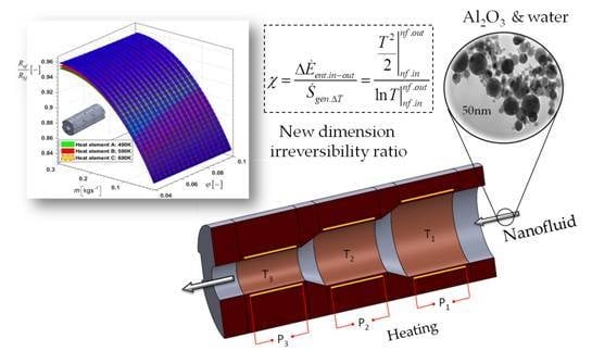
20]. Entransy of an object is the heat transfer ability during a given time period, while entransy dissipation is essentially the thermomass energy dissipation during heat transfer. In this paper, three cylindrical heating elements are analyzed, with an independent electrical source, placed alternately one after the other, thus forming a sectional heating channel. Nanofluid flows through this sectional channel and, thus, heats up. The nanofluid analyzed consists of a base fluid (water) and Al
2O
3 nanoparticles.
Furthermore, the nanofluid is used as the working medium with different values of the nanoparticle volume fraction, flowing at different flow rates, through different, linearly connected heating elements. This paper is an extended conference paper [
21], in which we introduced the new dimension irreversibility ratio. The entransy flow dissipation rate of three serially-connected cylindrical heating elements was analytically modeled and analyzed in this paper. The analytical analysis was conducted for the entransy flow dissipation rate, the new dimension irreversibility ratio, and the thermal resistance.
2. Materials and Methods
A hollow electric cylinder heater is inserted inside a thermo-insulating cylindrical body of larger diameter to form a single cylindrical heating element. Three cylindrical heating elements (
Figure 1), with an independent electrical source, are positioned alternately one after the other to form a sectional heating duct. The inlet temperature of the nanofluid is 293 K, while its mass flow rate is varied. The temperatures of the three cylindrical elements had constant values of 400 K, 500 K, and 600 K, differently positioned in the nanofluid’s flow direction. The cylindrical heating elements are relatively small, while the nanofluid flow is selected so that no evaporation of the nanofluid can occur as it passes through the three heating elements. Certainly, when using multiple heating elements, it is necessary to provide a ratio between the temperature of the heating elements and the flow rate to maintain a single-phase flow. In the analytical analysis, the temperatures of the three heating cylinders were 400 K, 500 K, and 600 K. In the same arrangement, the inner diameters of the hollow cylinders were 15 mm, 11 mm, and 7 mm in the nanofluid’s flow direction. The cylindrical heat elements are made of PTC ceramic heating elements with insulating film. This PTC heater has many advantages, such as a constant temperature, a long lifetime, safe usage, and high efficiency for both low voltages (3–36 V) and high voltages (110–380 V).
The paper analyzes the entransy flow dissipation rate, thermal entropy generation, and thermal resistance for different positions of the cylindrical heating elements.
In order to eliminate the effect of a sudden decrease in the cross-section on the pressure drop and the appearance of local turbulent nanofluid regions, a thermal insulation transition element was inserted between each heating element. In this way, the effect of the sudden change in the cross-section on the values of the local convective heat transfer coefficient can be neglected.
The effective length of the hollow heating element is less than the total length of the heating element,
Lef <
L. This minimizes the influence of the nanofluid at the inlet and outlet of the heating element on the local efficiency of the surface of the cylindrical heating element. The thermal interaction between the hollow cylindrical heaters and the nanofluids can be represented by balance Equation (1):
The density and specific heat capacity of the nanofluid are represented by Equations (2) [
22], and (3) [
23]:
where
mnp and
cnp are the mass and specific heat capacity of the nanoparticle,
mbf and
cbf are the mass and specific heat capacity of the base fluid. After grouping the physical sizes, we obtain:
where
Tnf is the nanofluid’s temperature,
Th is the temperature of the inner cylindrical element,
φ is the nanoparticle volume fraction,
ρnp and
cnp are the density and specific heat capacity of the particles,
is the mass flow of the nanofluid, and
ρbf and
cbf are the density and specific heat capacity of the base fluid. If the heat transfer between the surface of the heating elements and the environment is neglected, then from Equation (4) it follows that:
where
L is the length of one heating element and
Tnf.out and
Tnf.in are the outlet and inlet temperatures of the nanofluid. For the turbulent flow of nanofluid (Al
2O
3—water, 13 nm diameter spherical nanoparticles), the Nusselt number relation can be used [
24]. In this case, the convective heat transfer coefficient is represented by Equation (6):
where the expression for dynamic viscosity [
25] is:
while the nanofluid thermal conductivity [
26] is:
where
λnp and
λbf are the thermal conductivity of the nanoparticle and the base fluid, respectively.
After integrating Equation (5), the outlet nanofluid temperature of the first cylindrical heating element is:
The resulting expression for the outlet temperature of the first heating element, Equation (9), can also be used for the other heating elements. Thus, in the case of three cylindrical heating elements (
Figure 1), the fluid’s outlet temperature of the first heating element represents the fluid’s inlet temperature of the next heating element.
Equation (9) is used for each heating element, changing the internal diameters
D1,
D2, and
D3, and the convective heat transfer coefficients α
1, α
2, and α
3. Finally, the nanofluid’s outlet temperature of the third element is shown by Equation (10):
where
Th1,
Th2, and
Th3 are the inner surface temperatures of the cylindrical heating elements. The lengths of all three heating elements are
L, while their inner diameters decrease from
D1 to
D2 to
D3. Accordingly, the velocity of the nanofluid is different in each heating element and has the average values
wnf.1,
wnf.2, and
wnf.3, (
Figure 1). The entransy flow dissipation rate [
14], during nanofluid heating when the nanofluid passes through the three heating elements is:
In order to mathematically connect the entransy flow dissipation rate and the thermal entropy, a new dimension irreversibility ratio (
χ) is introduced, represented by Equation (12). This equation does not cover hydraulic-generated entropy resulting from hydraulic irreversibility in the flow of nanofluids through the heating elements.
Maximizing the new dimension irreversibility ratio χ is achieved by maximizing the entransy flow dissipation and minimizing the thermal-generated entropy. The new dimension irreversibility ratio χ is a function of two variables, entransy flow dissipation and thermal entropy, which can differentially affect the total change Δ
χ. Derivation of Equation (12) yields:
or written as a relative ratio:
According to Equations (13) and (14), a relative change in Δ
χ/
χ can be determined if, during the heating process, the increases in the nanofluid’s temperature are 20 °C, 40 °C, and 60 °C (
Table 1).
According to
Table 1, the relative changes in entransy flow dissipation and thermal entropy are approximately the same. This provides a convenient opportunity to apply the optimization of Equation (14). Maximizing the relative change in the new dimension irreversibility ratio can be achieved by increasing the difference between the relative changes in entransy flow dissipation and thermal entropy. This maximization of d
χ/
χ can be used to optimize different heat-fluidic devices. According to Equation (14), entransy flow dissipation and thermal entropy can be derived from Δ
Tnf and written in a relative form; see Equations (15) and (16):
In the case of three cylindrical heating elements, Equation (12) takes the form:
On the other hand, the entransy dissipation number Δ
ε presents the relationship between the actual entransy flow dissipation and the maximum entransy dissipation; see Equation (18). For a single heating element, this number Δε can be described as:
where
Th is the heating element’s surface temperature along its length. In the case of three heating elements with temperatures
Th1,
Th2, and
Th3 and internal diameter
D1,
D2, and
D3, the entransy dissipation number is:
For three cylindrical heating elements, a comparison of the new dimensionless irreversibility ratio and the entransy dissipation number is described in the next equation:
The total thermal resistance of the nanofluids when they pass through three regularly connected cylindrical heating elements is represented by Equation (21):
3. Results
By introducing some constraints, we analytically modeled the thermal interaction between the heating elements and the nanofluid’s flow.
The nanofluid’s mass flow, the temperature of the internal heating surface, and the nanoparticle volume fraction were varied. The temperatures of the internal heating surface had two arrangements: (1) 400 K, 500 K, and 600 K, and (2) 600 K, 500 K, and 400 K. The geometric arrangement of these heating elements is the same, with inner diameters of 15 mm, 11 mm, and 7 mm.
According to the analytical modeling carried out by using Equations (1)–(21), the following results were obtained. The characteristic physical sizes of the base fluid and nanoparticles are presented in
Table 2. The same table shows the values of the geometric parameters according to
Figure 1. For the nanofluid, Al
2O
3 was used for the basic nanoparticles, while the base fluid is water. The concentration of Al
2O
3 nanoparticles varied from 0.01 to 0.07, and to a maximum value of 0.3. The preparation method for Al
2O
3 nanoparticles is two-step dispersion in the base fluid.
For only one heating element, the inner diameter is 0.015 m, at different mass flows and temperatures of the internal heating surface. In this case, the ratio of the entransy flow dissipation rate for the nanofluid and the base fluid is shown in
Figure 2.
The entransy flow dissipation rate has a maximum value when the nanofluid is used, and this value increases linearly as the temperature of the inner surface of the cylindrical heating elements increases.
Additionally, for the case of only one cylindrical heating element whose inside diameter is 0.015 m, the new dimension irreversibility ratio
χ has high values of about 10
4 K
2 (
Figure 3).
The value of this dimension ratio increases with increasing temperature of the inner surface of the cylindrical heating element. On the other hand, increasing the mass flow of this fluid decreases this ratio. As the fluid or nanofluid is retained for a shorter time in the cylindrical heating element, its outlet temperature and, therefore, the new dimension irreversibility ratio χ become lower.
In the case of using three cylindrical heating elements (
Figure 1), the values of the entransy flow dissipation rate are shown in
Figure 4. In the same figure, the temperatures of the heating elements and their internal diameters are varied. Thus, in the first case, the temperatures of the heating elements increase from 400 K to 500 K to 600 K, whereas, in the second case, the temperatures decrease from 600 K to 500 K to 400 K. As the nanoparticle volume fraction and the mass flow increase, the entransy dissipation rate increases (
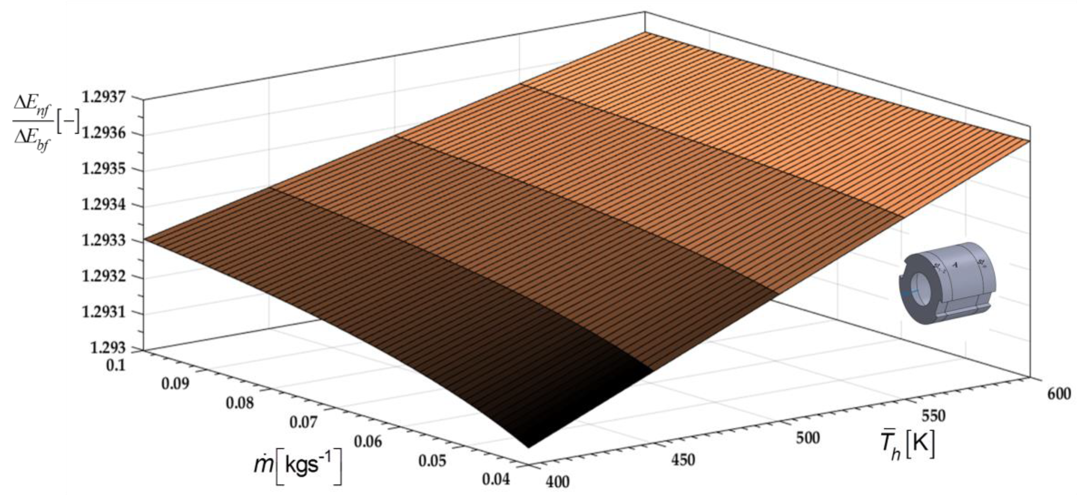
Figure 4). In the case of a temperature arrangement of 400 K, 500 K, and 600 K, the entransy flow dissipation rate increases faster.
The use of nanofluids instead of the base fluid changes the values of the thermal resistances, as shown by their dimensionless relationship in
Figure 5.
The thermal resistance of the nanofluid is smaller than that of the base fluid. For heating element temperatures from 600 K to 500 K to 400 K, the minimum thermal resistance ratio is at a nanoparticle volume fraction of 0.17. The thermal resistances of the nanofluid and the base fluid, at heating element temperatures of 600 K, 500 K, and 400 K, are the same for the two nanoparticle volume fraction values of
φ = 0 and
φ = 0.28. In this case, the internal diameters of the heating elements and the temperatures of their surfaces are reduced: A (600 K,
D = 15 mm), B (500 K,
D = 11 mm), and C (400 K,
D = 7 mm). At the same time, the nanofluid’s temperature rises as it passes from heating element A to heating element C. The heat exchange between the heating elements and the nanofluids decreases, and thus the increase in nanoparticle volume fraction loses importance. After
φ = 0.17, the
Rnf/
Rbf thermal resistance ratio approaches 1. Accordingly, the optimum value of the nanoparticle volume fraction for this case is 0.17. In the first case, for each heating element the following applies: A (400 K,
D = 15 mm), B (500 K,
D = 11 mm), and C (600 K,
D = 7 mm), so there is a continuous increase in the heat exchanged between the heating elements and the nanofluid. The influence of the nanoparticle volume fraction rapidly reduces the thermal resistance of the nanofluid relative to the thermal resistance of the base fluid. With increasing nanoparticle volume fraction, the ratio
χnf/
χbf grows rapidly, especially for heating element temperatures of 400 K, 500 K, and 600 K (
Figure 6).
The dimensionless ratio of the entransy dissipation number Δ
εnf/Δ
εbf (
Figure 7) shows the same qualitative trend as the new dimensionless irreversibility ratio Δ
χnf/Δ
χbf, as shown in
Figure 6. On the right side, the ratio Δ
εnf/Δ
εbf is greater than the ratio Δ
χnf/Δ
χbf. In both cases, the heating element arrangement of 400 K, 500 K, and 600 K shows a greater influence when nanofluid is used.
The dimensionless ratio of thermal resistance,
Rnf/Rbf, as a function of nanoparticle volume fraction φ and mass flow is shown in
Figure 8. This figure shows the individual influences of each of the three cylindrical heating elements, A, B, and C, which are mounted with inner diameters
D1 of 15 mm, 11 mm, and 7 mm in the flow direction. The lowest thermal resistance during the nanofluid flow is provided by heating element A (
D1 = 15 mm, 400 K). The lowest value of the ratio
Rnf/Rbf is achieved for the highest nanoparticle volume fraction
φ of 0.1.
If the cylindrical heating elements are kept in the same arrangement (15 mm, 11 mm, and 7 mm) in the flow direction and the inner surface temperatures are 600 K, 500 K, and 400 K, respectively, then the ratio
Rnf/Rbf is as shown in
Figure 9. As in the first case (
Figure 8), the cylindrical heating element A shows the smallest influence of nanofluid on the thermal resistance ratio
Rnf/Rbf.
In order to verify the established mathematical model of nanofluid temperature change, when passing through three cylindrical heating elements, an experimental test was performed,
Figure 10.
For the nanoparticles used Al
2O
3 while distilled water was used as the base fluid. An electric current regulator was also used to vary the constant temperatures of the heating PTC (positive temperature coefficient) elements. After the nanofluid temperature was measured, the same control setup was also used to measure the base fluid temperature,
Figure 10.
Since the basic methodology in this paper is analytical modeling, experimental testing was used only to measure the rise in temperature of nanofluid and the base fluid. Indirect determinations of other physical quantities in this paper were not considered. Additionally, a comparative analysis of the obtained results was performed with the results obtained by analytical modeling. The following figures show a comparative analysis of the increase in water and nanofluid temperature with a nanoparticle volume fraction of 0.3,
Figure 11, and 0.15,
Figure 12.


