From a performance point of view, compared to similar motors with distributed winding, in most cases, PMSMs with FSCW present:
Considering the overall system, consisting of the PMSM and its load or prime mover, the FSCW permits a direct coupling to be achieved, when the required speed at a rated frequency is low, so a gearbox would be unnecessary and therefore the efficiency of the entire system would be increased, reducing also its size, weight, noise, maintenance costs, and failure rate.
From the manufacturing point of view, this design allows for easier and faster insertion of the coils into the slots, which, generally, have to be open, with the following drawbacks:
In order to mitigate the problems mentioned above deriving from the design of the stator slot opening, it is possible to use magnetic or semi-magnetic wedges, with the effect of simulating semi-closed slots. In the literature, different solutions have been proposed for this purpose for different types of electrical machines, but very few papers have focused on radial PMSMs and in particular on high torque and low speed SPM machines, as in this research.
1.1. State of the Art of the FSCW Machines
FCSW has been considered in the last 15 years as a valid alternative for PMSMs with respect to the traditional distributed winding. Many researches are present in the literature, mainly related to three-phase radial-flux machines [
1,
2,
3,
4,
5], but also on axial-flux [
6], tubular and flux-switching machines, and to machines with more than three phases [
7]. Nevertheless, in this paper, the analysis of FCSW has been limited to the most widespread application, i.e., three-phase radial-flux machines. The first most significant researches on this topic are reported in [
1,
2,
3,
4,
5], but more recently, other interesting papers have been published and the conclusions of some of them are reported in the following.
One of the drawbacks arising from FCSW is the increase in the rotor losses, due to the large amount of magnetomotive force harmonics produced by this type of winding. In [
8], the effects of multilayer windings on rotor losses, especially the eddy-current losses in the permanent magnets of IPM machines with FSCW, were studied by means of the 2-D finite element analysis.
Another winding method is presented in [
9] to eliminate both the sub and super space harmonics of the FCSWs in which the stator slot numbers are integer multiples of six. The proposed method is based on three concentrated single-layer windings in which the number of turns in one layer is optimized while the other layers are moved to cancel the subharmonics. The application of the proposed winding concept to a PMSM demonstrates the cancellation of dominant sub and super harmonics, reduction of the total harmonic distortion (THD), reduction of torque ripple, and minimization of core loss.
In [
10], a multi-layer winding was designed to achieve an innovative symmetrical FSCW with unconventional slot–pole combinations. A general design methodology for this purpose is presented and validated by finite element analysis. The application of an unconventional FSCW to a shipboard surface permanent-magnet machine prototype is presented to illustrate the possible practicality of this type of winding; tests on the prototype for experimental validation are reported.
In [
11], a method is proposed to reduce the torque pulsation of the three-phase FSCW interior permanent magnet (IPM) motors by lowering the subharmonics. The key principle of this method is the selection of an optimized six-layer winding with a different number of conductors. The optimized six-layer winding is used to suppress the first subharmonic and ensure that the second subharmonic is zero in a novel 9-slot/8-pole IPM motor.
Based on the consideration that the increase in the number of pole pairs leads to a lower electromagnetic yoke, and therefore to lower vibration and magnetic noise, in [
12], the influence of different numbers of pole pairs on the vibroacoustic design aspects of the machine was studied, considering the natural frequencies under a variable speed analysis. The paper aimed to determine the optimal number of pole pairs for a low-speed and high-torque PMSM with FSCWs for wind turbine applications. Both 3-D finite element analysis and experimental investigations were used.
From this analysis, it is clear that in the last years that the research in this field has been focused in particular on the design of special windings to solve the drawbacks arising from FCSWs; however, this choice could impose many constraints for the design of the machine and involve manufacturing complications and higher costs for its realization.
1.2. State of the Art of the Magnetic Wedges Employed in Rotating Electrical Machines
The first researches on the use of magnetic wedges date back to at least 50 years ago and mainly concern the application to induction motors. The problem starts from the consideration that high-power rotating electrical machines, with the stator winding connected to the voltage in the order of a few kilovolts, require the manufacture of form-wound coils, which are made and insulated separately, and then inserted into the stator slots, which must be open. However, the open slots have some drawbacks, which are derived from the variations in the airgap permeance produced by the relatively wide opening of the slots. These drawbacks include the high frequency no-load losses, higher magnetizing current due to the increase in the effective airgap, consequent reduction in efficiency, and the power factor. The influence of the stator slot opening is stronger in induction motors, which have a higher “slot-opening/airgap” ratio than synchronous machines [
13]. This is related to the fact that induction machines require a smaller airgap with respect to synchronous ones, due to the need to contain the value of the magnetizing current. Even if this requirement is valid, especially for large machines, the first studies have been applied to small ones.
A first investigation on a 3.7 kW motor showed that the use of magnetic wedges in induction motors can improve their performance, especially at full load [
13]. However, the paper does not answer questions related to the mechanical strength and durability of the wedges under service conditions in large machines. A second study proved that soft ferrite magnetic wedges in a 0.75 kW induction motor decrease the 17th and 19th asynchronous torques (this effect is equivalent to the rotor skewing), but they are not able to reduce the 5th asynchronous and synchronous torques [
14].
A more recent paper, focused on both induction and synchronous motors, starts from the assumption that it is possible to obtain a high power density in rotating electrical machines by increasing the flux density at the airgap, and in particular by shortening the length of the airgap [
15]. Since this solution increases the ripple flux density of the tooth and, consequently, the losses on the surface of the poles, magnetic wedges have been proposed to reduce these losses. Magnetic wedges with a relative permeability,
µr, from 10 to 30 were evaluated and the calculated and measured results on large motors (500 and 745 kW) indicated the effectiveness of the magnetic wedges, selecting
µr = 10 as the most suitable.
In [
16], the effects of magnetic wedges with
µr = 8 and different dimensions were evaluated in the stator slot ripple components of the airgap flux density distribution and in the rotor current of a 55 kW squirrel cage induction motor. The simulated and experimental results showed a reduction of these components but also revealed that a thicker magnetic wedge can induce an increase of the slot leakage flux and a decrease of the power factor.
The impact of magnetic wedges in high power induction motors has also been studied in recent years. An interesting study is reported in [
17], where the effects of two commercial magnetic wedges were simulated by finite element (FE) analysis and experimentally tested on a squirrel cage induction motor of 1660 kW, 6.6 kV. Both wedges have a relative permeability of few units, based on the value of the magnetic flux density. The authors prove that magnetic wedges offer the following advantages: (i) Reduction of the magnetizing current (less no-load current); (ii) consequent reduction of the Joule losses in the stator winding and increase of the efficiency of the machine; and (iii) in the case of totally enclosed fan cooled (TEFC) motors, a further benefit is the reduction in temperature rise. However, a qualification process is needed to ensure a reliable magnetic wedge system, as the flux density increases with greater permeability and the forces acting on the magnetic wedges also increase.
In [
18], the influence of semi-magnetic wedges with
µr = 10 on the harmonic content of the magnetic field at the airgap and on the electromagnetic characteristics of a 4 kW induction motor was studied through FE analysis. The results indicate that these wedges lead to a decrease in the airgap magnetic field space harmonic content. In addition, the electromagnetic torque is characterized by significantly lower oscillations, resulting in a longer bearing lifecycle. This behavior leads to an improvement of the motor efficiency but also to a lower power factor at the rated speed. The performances of a 2.2 kW induction motor with magnetic wedges of different permeability were evaluated in [
19] by FE analysis. The authors concluded that this solution improves the motor performance, even if it tends to decrease drastically when
µr > 20, as most of the flux lines is shorted in the wedges. Another recent paper reports a study on a 120 kW, 350 V induction motor with a squirrel cage rotor [
20]. The FE analysis and the experimental tests showed that the magnetic wedges with
µr = 4 significantly reduced the load current (thanks to a reduction of the magnetizing current) and increased both the power factor and the efficiency. However, when the relative permeability of the magnetic wedges was greater than 30, the torque of the motor decreased and, consequently, both the motor efficiency and the power factor tended to decrease due to the leakage fluxes. The optimal value of the magnetic wedge relative permeability, corresponding to the maximum efficiency of the motor, can be found for each case by using FE analysis. The use of magnetic wedges has also been evaluated in a special type of induction machine, i.e., a 250 kW brushless doubly fed machine, which can be employed for offshore wind power generation. The results show that magnetic wedges increase the series inductance in the equivalent circuit, which significantly affects the reactive power control and the rating of the converter [
21]. A very recent paper explored the impact of adopting semi-magnetic wedges in wound field synchronous machines and concludes that they can be useful for reducing the pole face losses, the stator air-gap Carter coefficient, and, as a consequence, the rotor DC current required for the rated flux together with the associated loss and temperature rise [
22].
Over the past 20 years, some papers have addressed axial flux permanent magnet machines (AFPMs) with slotted winding, which are suitable for electric traction applications, such as wheel motors. The slotted winding allows a slight flux weakening capability, but it generates a significant cogging torque and a large harmonic content in the back electromotive force (e.m.f.), due to the magnetic anisotropy of the stator. The use of magnetic wedges, with a relative permeability in the range between 10 and 100, causes an increase in the phase inductance, as well as a good reduction of the cogging torque. In [
23], a 2D FE procedure, validated with experimental tests, was applied to a three-phase machine, with a single central stator and two rotors, one slot per pole and per phase, with a nominal power of 8 kW. Magnetic wedges significantly increase the phase inductance while the mutual inductance is nearly not affected. As a drawback, this solution increases the axial force between the stator and rotor by about 20% in comparison to standard non-magnetic wedges. A similar machine was simulated in [
24,
25], by means of 2D and 3D FE models, considering magnetic wedges of different heights and with a variable gap in the center of the wedge. The performances of this machine were analyzed both at no-load and at load, highlighting the advantages and disadvantages offered by the various solutions.
A new magnetic wedge design was rated for an AFPM in [
26,
27,
28]. It was obtained from a normal magnetic wedge by milling a straight hollow groove along the length of the wedge. The groove was filled with a non-magnetic bar, which had a purely mechanical function of increasing the strength of the wedge. The main influences of this magnetic wedge design can be observed in terms of the cogging torque and stator phase slot leakage inductance. These two effects determine the most convenient cross-section design of the wedge, depending on the specific application. The large inductance allows to advantageously reduce the flux-weakening current and helps to reduce the short-circuit current, which is very important, especially in permanent magnet machines, to avoid demagnetization in the case of failure.
The influence of magnetic wedges on a 110 kW radial flux interior permanent magnet (IPM) motor with concentrated winding was investigated in [
29], using flux 2D analysis and experimental tests. The machine was designed for traction applications, with a torque demand in the low speed area up to 2.5 times the nominal torque, and in the high speed area, a good field weakening capability. Several wedge materials were evaluated, with a relative permeability of 1, 1.5, 3, 30, 300, and 500. The authors showed that magnetic wedges reduce iron losses and, above all, permanent magnet losses, around the rated speed. However, magnetic wedges with a relative permeability greater than 3 do not provide an advantage but rather a disadvantage, since they significantly reduce the maximum torque.
Recently, magnetic wedges were considered for applications to switched reluctance machines, which has two important drawbacks: Torque ripple and stator vibrations. Using FE simulations, the authors demonstrated that, although the introduction of magnetic wedges degrades the average torque, it does reduce the radial force and torque ripples [
30].
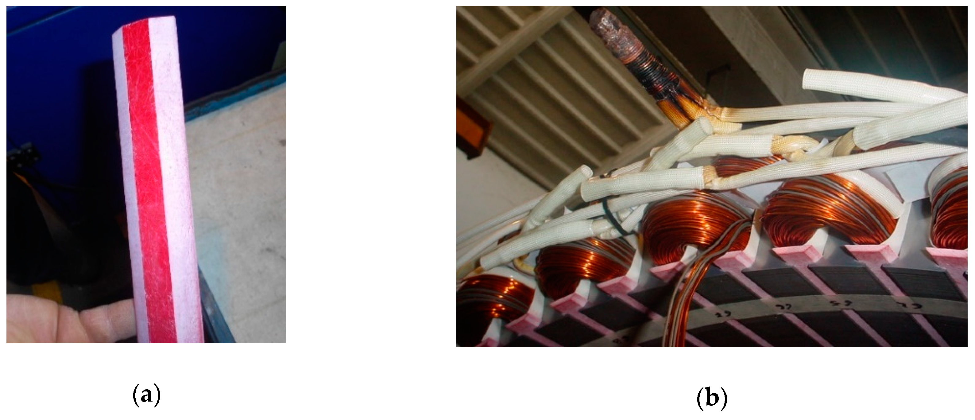
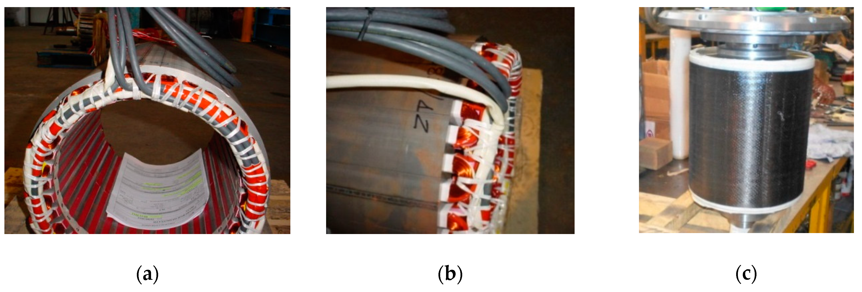
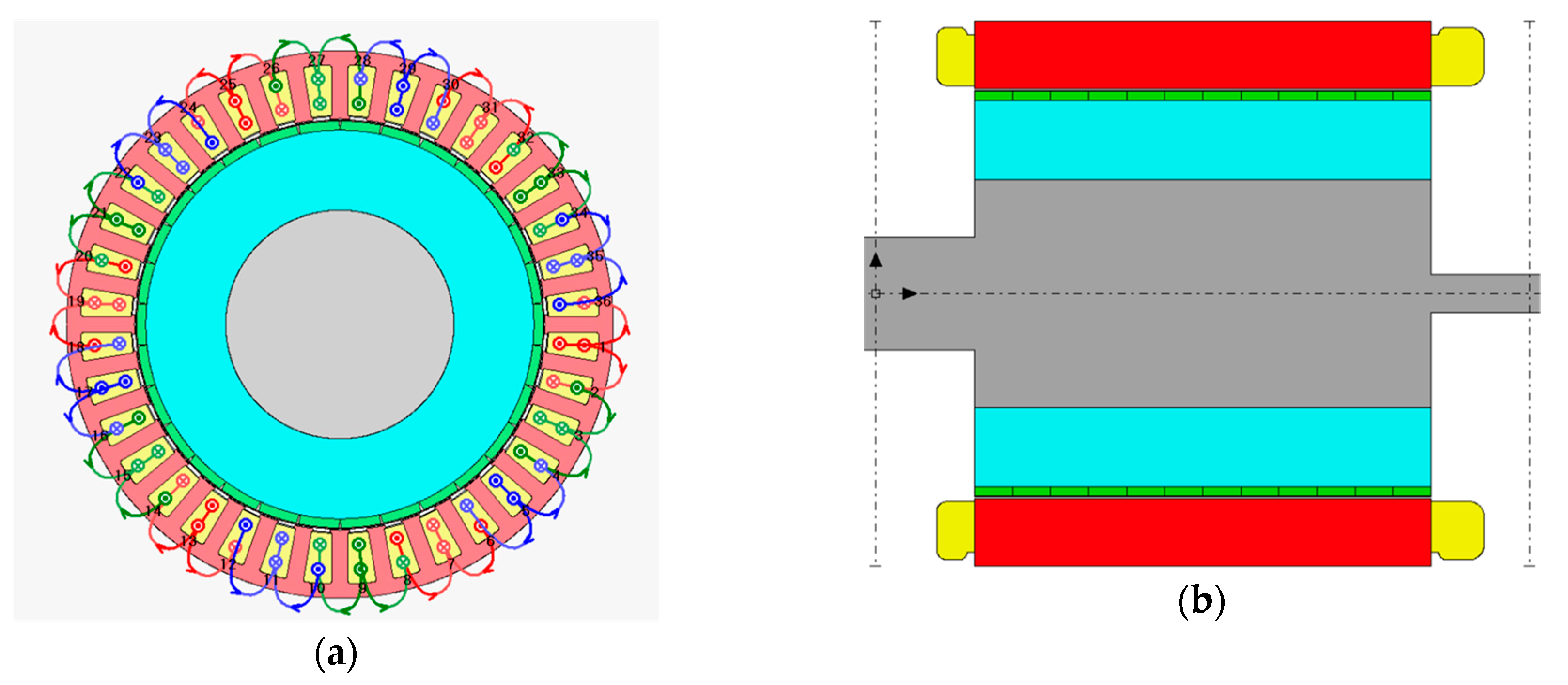
For a better understanding, two illustrations of wedges for FSCW machines are reported in
Figure 1: Note that these wedges are non-magnetic, but the shapes of magnetic wedges are the same and also the method to assemble them in the stator slots.
1.3. Novelties of the Paper
In this paper, first of all, the main issues in the design of FSCW-SPM machines will be investigated, with particular attention to the effect of this type of winding on the losses of the machine. After that, a preliminary study on the effects of magnetic wedges in SPM machines will be carried out, in order to choose the best compromise for the value of magnetic permeability of these wedges. Finally, a case study will be introduced and the most suitable characteristics of the wedges for this case will be studied, in terms of material, geometry, and their combinations, through finite element (FE) simulations, with the aim of optimizing motor performance. Particular attention will be paid to the reduction of power losses in the magnets. Different configurations of the magnetic wedge will be evaluated, not only for the specific application but also to evaluate the effects derived from this type of wedge on machines with other characteristics, in order to obtain a broader estimate of the benefits and critical problems deriving from this change in the stator design.
The main differences and contributions of this paper compared to the literature are given by: (i) The proposal to use magnetic wedges to solve the problems provided by FSCW for SPM machines with radial flux for applications with high torque and low speed; and (ii) the evaluation of an innovative unconventional magnetic wedge that allows optimization of the overall performance of this type of machine.


